


LCD TV SERVICE MANUAL
Model list
KLC-2011US
KONKA GROUP CO,LTD.
Digital Flat Display Division

IMPORTANT SERVICE SAFETY INFORMATION
Operating the receiver outside of its cabinet or with its back removed involves a shock hazard. Work on these
models should only be performed by those who are thoroughly familiar with precautions necessary when working on
high voltage equipment.
Exercise care when servicing this chassis with power applied. if carelessly contacted, can cause serious shock or
result in damage to the chassis. Maintain interconnecting ground lead connections between chassis, escutcheon, picture
tube dag and tuner when operating chassis.
When it is necessary to make measurements or tests with AC power applied to the receiver chassis, an Isolation
Transformer must be used as a safety precaution and to prevent possible damage to transistors. The Isolation
Transformer should be connected between the TV line cord plug and the AC power outlet.
It is important to maintain specified values of all components and anywhere else in the received that could cause
a rise in operating supply voltages. No changes should be made to the original design of the receiver.
Components shown in the shaded areas on the schematic diagram and/or identified by in the replacement parts
list should be replaced only with exact factory recommended replacement parts. The use of unauthorized substitute
parts man creates may create shock, fire, or other hazards.
Before returning the receiver to the user, perform the following safety checks:
1. Inspect all lead dress to make certain that leads are not pinched or that hardware is not lodged between the chassis
and other metal parts in the receiver.
2. Replace all protective devices such as non-metallic control knobs, insulating fish papers, cabinet backs, adjustment
and compartment covers of shields, isolation resistor-capacitor networks, mechanical insulators etc.
3. To be sure that not shock hazard exists, a check for the presence of leakage current should be made at each exposed
metal part having a return path to the chassis (antenna, cabinet metal, screw heads knobs and/or shafts, escutcheon,
etc.) in the following manner.
Plug the AC line cord directly into a 110V/220V/240V, AC receptacle. (Do not use an Isolation Transformer
during these checks.) All checks must be repeated with the AC line cord plug connection reversed. (If necessary, a
non-polarized adapter plug must be used only for the purpose of completing these checks.)
PLEASE READ BEFORE ATTEMPTING SERVICE
1. Use an Isolation Transformer when performing any service on this chassis.
2. Never disconnect any leads while receiver is in operation.
3. Disconnect all power before attempting any repairs.
4. Do not short any position of the circuit while the power is on.
5. For safety reasons, replace components any with identical replacement parts (SEE PARTS LIST).
6. Before alignment, warm up the TV for at least 30 minutes.
7. When removing a PCB or related component, after unfastening or changing a wire, be sure to put the
wire back in its original position.
8. Inferior silicon grease can damage IC's and transistors. When replacing IC's and transistors, use only
specified silicon grease. Remove all old silicon when applying new silicon.
9. Before removing the anode cap, discharge eletricity because it contains high voltage.
A. SPECIFICATION
System : NTSC-M
Channel : Antenna 2-69
CATV 1-125
IF Frenquency Video: 45.75MHz
Sound: 42.17MHz
Chroma: 41.25MHz
Audio output power 10%THD 1W X 2
Antenna Impedance 75Ω(Unbalance)
Power Consumption 65W
Power Supply : AC~120V,60Hz
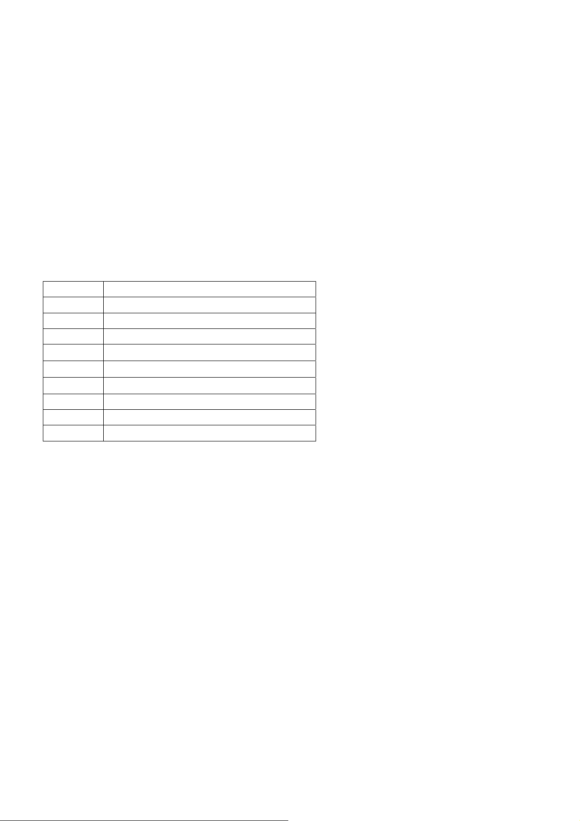
item Port list
1 RF cable
2 Y 、Pb /Cb、Pr /Cr
3 Audio2(Y、Pb/Cb、Pr/Cr Audio input)
4 VGA
5 Audio3(PC Audio input)
6 Video and Audio1
7 S-Video
8 Headphone audio output
9 Power port
ADJUSTMENT MANUAL
Ⅰ. TEST NOTE
1. Please follow the pointed test steps and choose the right test equipment to conduct
adjustment, otherwise good effect of Unit could not be obtained. The unit should be
warmed up for 30 minutes before adjustment and every parameter should be adjusted

repeatedly till the optimum value obtained, the pointed voltage value should be ensured
during test to get satisfied test result.
2. Test environment
1) Temperature : 15°C-35°C
2) Relative Humidity : 45-75%
3) Air pressure : 86-106KPa
3 Test equipments(The following equipment should be calibrated before testing)
1) Computer 1 set
2) Multi-meter (VICTOR VC9801) 1 set
3) Video Signal Generator (Chroma Model 2227/2327) 1 set
4) Color Analyzer (Chroma Model 7120 ) 1 set
5) DDC card (DYNACOLOR, INC D8330) 1 slice
6) TV Video Signal Generator (FLUKE PM54200) 1 set
4 Factory mode adjustment
4.1 Enter factory mode adjustment
Using the remote control, press Menu button once first , then press PRE.CH(or named
RECALL) button five times,and you can see manufacture menu on the LCD panel.
4.2 factory menu operation method
Press the channel +/- button to selection the sub menu of factory menu(including F、E、
UOCⅢ、RGBTemp、Temp), and press the vol+ to enter the sub menu and setting the value.
4.3 exit the factory menu
Press the MUTE button again and again or turn off the TV, it can exit the factory menu.
4.4 AGC adjustment
In TV mode,Receive 60dB split field signal.Enter factory mode menu “UOC Ⅲ ” item,
press”CHAN▽” to select “RF AGC” ,then use VOL+/- to adjust the item until the voltage of Pin
1 of N100 to be about 2.5V±0.2V,then noise wave of the picture point disappears.
4.5 White calibration adjustment
1 Receive black or white signal under AV or PC mode, adjusting brightness and contrast to set
the brightness to 15Nit in dark area and 90 Nit in bright area.
2 Adjust white balance.Press“MENU”button once, then press “PRE.CH”five times to enter
factory menu, select “Temp” Menu,
Adjust Red 0-100
Green 0-100

Blue 0-100
N
N
p
3 Adjusting chromaticity coordinates of black and white to fit the requirement (X=0.285,
Y=0.293), or plug automatic calibration system to adjust white calibration automatically.
BLOCK DIAGRAM
CVBS,S-Video
Signal Block Diagram
100
Tuner
+12V
Supply
AGC
T101
M3953
T102
M9352
VIF
SIF
Audio L,R
MAIN IC
TDA15001H
LED R,G
N401
KEY B1、B0
IR
PWRON
DDC/HWI2C
Earphone
speaker
ort
Y
Pb
Pr
Port
VG
A
Audio
201
TDA1517
+12V
Supply
Audio 2
L,R
Y,Pb/Cb,Pr/Cr
VGA
Audio IN
VGA R,G,B
VGA Hs,Vs
VGA-CLK
VGA-DAT
AMP_L
AMP_R
AU2IN_L,R
AU3IN_L,R
UOC R,G,B
N303
PI5V330
Y_G
Pb_B
Pr_R
N301
PI5V330
YUVHs
YUVVs
N501
MST518
SCL
SDA
M_Rst
M_CLK
M_SDA
M_CS
To N401
N302
24LC21
BKLON
VCC-5Ua
VCC-3.3VUSB
VCC+1.8a
VCC+1.8b
VCC-PAN
LCD
PANEL
3.3V Supply
2.5V Supply
DDC/HWI2C


IC BLOCK DIAGRAM
1 N401(TDA15001H1)
2 N501 (MST518)
Trouble Shooting

Key IC list
p
N
d
k
Item Type Maker Package Circuit No. Qty.
1 TDA15001H1 Philips QFP128 N401 1
2
MST518 MSTAR PQFP160 N501 1
3 24LC32A MICROCHIP SOIC-8 N402 1
4 24LC21A MICROCHIP SOIC-8 N302 1
5 MP1410ES-SOIC-8 MPS SOIC-8 N801,N802 2
6 FDS9435A FAIRCHILD SOIC-8 N803 1
8
11
12
14
TDA1517 PHILIPS SIL9MPF N200
FSAV330 FAIRCHILD9
TSSOP-16 N301,N303 2
TS5V330 TI
1117-3.3V 1117 serial SOT223 N804,N806 2
1117-2.5V 1117 serial SOT223 N805 1
Tuner AFT1/L301 Qingjia N100 1
1
Start order:
Tur n on t he
ower
401 RESET an
IO port initialize
N501electrify,
reset, initialize
Turn on bac
light lamp
Successful start
and LCD display
1)Verify the state of TV set.Please switch the TV on ,then verify the LED color. Red is
standby state and green is working state.
2)Checking Supply Power.If the color of LED is yellow,the power supply for signal board 。
N801 supply 5V and N802 supply 3.3V,N804、N806 supply 3.3V power(Test the PIN 2).N805
supply 2.5V(Test the PIN 2),D803 supply 8.3V,V401 and V402 supply 1.8V. All these are
for main IC N401,N501.
3)After turning on the power, if blank screen appears (no back light lamp), just
press POWER button several times, if blank screen still there.Check if the voltage of
every power supply is normal.
KLC--
1508US/1521US POWER SUPPLY SYSTEM
KLC
1508US/1521US POWER SUPPLY SYSTEM
4)Check if the crystal oscillator X501(14.318180MHz) X401(24.576MHz) oscillate or not,
and oscillate frequency is right or not.
5)Back light control signal (BKLON) of XS801 has high level (about 2.5V)
or not, if not, check whether fault soldered or short circuit happened。
6) If back light lamp is on while there is no display,check N407 and N501’s reset circuit
+12V
and the output of the oscillator to confirm the CPU and SCALER are working or not.If RGB
is abnormal,check N501;If RGB is working correctly and the other channel is
abnormal ,please check N501.
XS802
(KLC-1508US)
XS803
(KLC-1521US)
N200
TDA1517
XP801
N802
MP1410
N805
MP1410
N803
9435A
To Audio
amplifier
To inverter
Panel Power
to LVDS port XS501
+5V
+5V_SW
+12V
+12v
+3.3V_SW
N806,N804
1117-3.3V
N805
1117-2.5V
To Tuner
To IR
To N401
To N301,N303(only for KLC-1521US)
+3.3V
+2.5V
Supply for
N401,N501
Supply for
N501
 Loading...