

Page 1
24624 Leuchtenstativ
- Attraktives Stativ dank eleganter Optik bei geringem Platzbedarf
- Tragkraft bis zu 18 kg (max.)
- Höhenverstellbare Stativrohrkombination (mit Rastbolzen und Klemmschraube)
- Schwere Sockelplatte aus Stahl, mit Tragegriff, Steckeröffnung und 4 Filzfüßen
- Höhe min. 1400 / max. 2400 mm; Auszug: ø 35 mm,
- M10-Gewinde; Sockel 550 x 550 mm, Gewicht: 18 kg
SICHERHEITSHINWEISE
A. ALLGEMEIN
A. - Tragkraft max. 18 kg
A. - Montage und Handhabung nur durch geeignetes Personal
A. - Bei Montagearbeiten Schutzhandschuhe tragen
A. - Verwendung nur im Innenbereich
A. - Auf geeigneten, d.h. ebenen und tragfähigen Untergrund achten
A. - ACHTUNG! Die Sockelplatte ist sehr schwer und stellt bei unsachgemäßer
A. - Handhabung eine Gefährdung für Personen und Sachen dar.
A. - BEACHTE: insbesondere bei der Montage nicht fallen lassen oder
A. - Gliedmaße quetschen
A. - Sockelplatte und Rohrkombination müssen bis zum Anschlag fest
A. - verschraubt sein
B. AUFBAU, BETRIEB, DEMONTAGE
B. AUFBAU: Schraubverbindung zwischen Stativrohr und
B. Sockelplatte muss stets bis zum Anschlag angezogen sein
B. BETRIEB: Rohrkombination zentrisch belasten:
B. - außermittige Lasten beeinträchtigen die Standfestigkeit
B. - Rastbolzen 17 muss sich stets im Eingriff befinden
B. - und die Klemmschraube 19 angezogen sein
B. - Niemals Rastbolzen und Klemmschraube unkontrolliert lösen
B. DEMONTAGE: erst Traglast vom Auszugrohr entfernen und
B. danach das Stativrohr aus der Sockelplatte herausdrehen
C. SEITENKRÄFTE
C. - Seitenkräfte sind wegen der Kippgefährdung unbedingt zu vermeiden.
C. - Dazu zählen:
C. - a. außermittiger Schwerpunkt der Traglast
C. - b. Stöße, Berührungen, Erschütterungen, Wind, unebener Boden
C. - BEACHTE: Sicherheitsabstände einhalten, Unbefugte fernhalten
C. - Falls die Wirksamkeit dieser Maßnahmen nicht garantiert werden kann,
C. - (z.B. durch unkontrollierbare Nichteinhaltung des Sicherheitsabstandes)
C. - sind durch den Aufsteller zusätzliche Sicherungen vorzunehmen als da sind:
C. - Verankerung der Sockelplatte im Boden
C. - geeignete Erweiterung/Ausbau/Beschwerung der Sockelplatte
AUFBAUANLEITUNG
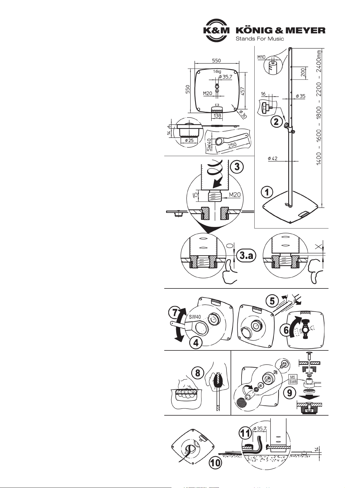
1 Sockelplatte an gewünschter Stelle mit Standfüßen nach unten auslegen.
2 Klemmschraube in Spannschelle eindrehen
3 Gewinde-M20 der Rohrkombination bis zum Anschlag fest in die
3 Sockelplatte einschrauben.
3.a Zwischen Rohr und Platte darf sich kein Luftspalt befinden
3.a BEACHTE: Verschraubung regelmäßig prüfen und ggf. nachziehen.
BENUTZERHINWEISE / FUNKTIONEN
AUSRICHTUNG der ROHRKOMBINATION
- Nachdem die Rohrkombination wie gefordert bis zum Anschlag eingedreht wurde,
- weisen deren Bedienelemente möglicherweise in eine unerwünschte Richtung.
- Dies kann korrigiert werden.
- Wir empfehlen dabei mit 2 Personen zu arbeiten: eine hält die Platte,
- die andere das Rohr
4 Kontermutter auf der Unterseite der Platte mit dem Schlüssel losschrauben
5 Das Rohr etwas hin- und her bewegen, damit sich die Gewindebuchse
5 aus der Platte löst
6 Rohr nun in gewünschte Richtung drehen und Gewindebuchse wieder
6 in die Platte führen
7 Kontermutter ansetzen und mit dem Schlüssel wieder fest anziehen
TRAGEGRIFF
8 Der komfortabel gestaltete Tragegriff schützt ihre Hände und macht Transport und
8 Installierung der Sockelplatte angenehmer und damit auch wesentlich sicherer.
STANDFÜSSE
Zum Schutz des Bodens ruht die Sockelplatte auf vier verschraubten Standfüßen
mit Filzauflage.
9 Gelockerte Standfüße mit einem Steckschlüssel (SW8 = M5) wieder
festschrauben.
KABEL-/STECKERÖFFNUNG
10 Optisch ansprechend: Kabel werden unter der Sockelplatte verlegt.
11 Technisch auf der sicheren Seite: die Öffnung bietet Platz für alle gängigen
11 Steckertypen und der Kunststoffring schützt das Kabel vor scharfen Kanten.
Vielen Dank, dass Sie sich für dieses Produkt entschieden haben. Diese Anleitung
informiert Sie über alle wichtigen Schritte bei Aufbau und Handhabung.
Wir empfehlen, sie auch für den späteren Gebrauch aufzubewahren.
AUFBAUANLEITUNG
AUSRICHTUNG der ROHRKOMBINATION
TRAGEGRIFF STANDFÜSSE
KABEL-/STECKERÖFFNUNG
Page 2
TECHNISCHE DATEN / SPEZIFIKATIONEN
KÖNIG & MEYER GmbH & Co. KG
Kiesweg 2, 97877 Wertheim, www.k-m.de
24624-000-55/76 Rev.09/Rev.01 03-80-834-00 12/18
Material
Platte, Füße, Rohre: Stahl, schwarz pulverbeschichtet
Gewinde: Stahl, verzinkt
Schelle: Zink-Guss, schwarz pulverbeschichtet
Kabelschutz: PA-6, schwarz
Tragegriff: TPE, schwarz
Traglast max. 18 kg zentrische Last
Abmessungen B x T x H: 550 x 550 x 2400 mm
Karton
Platte: 670 x 670 x 35 mm
Rohrkombination: 1400 x 115 x 5 0mm
Gewicht 18 kg
Zubehör
(optional)
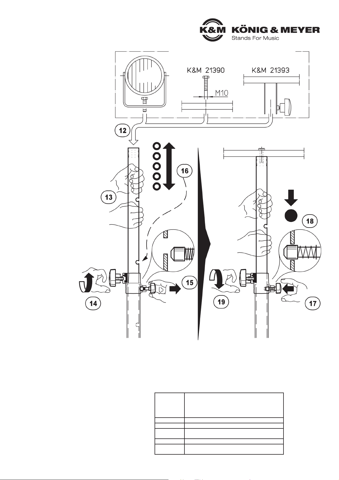
Traversen 21390, 21393
Tragetasche für Sockelplatte 24627
PRÜFEN, INSTANDHALTEN, REINIGEN
- Schonender Umgang mit dem Stativ erhält die Teleskopierbarkeit, die Tragkraft und die
- Sicherheit der Installation.
- Bei Wartungsarbeiten -stets im unbelasteten Zustand- auf evtl. Gefährdungen achten
- (Einklemmen, Anstoßen, Kippen).
- Zur Reinigung und Pflege am besten ein leicht feuchtes Tuch und ein nicht scheuerndes
- Reinigungsmittel benutzen.
LEUCHTE/N AM STATIV BEFESTIGEN
ACHTUNG!
Unterschätzen Sie nicht das Gewicht der Leuchten
12 aufsetzen und ausfahren der Traglast muss durch
10 fachlich und körperlich geeignetes Personal erfolgen,
10 Auszugrohr während der Höhenverstellung mit festem
10 Griff halten und stets mit Rastbolzen sichern.
DAS BEWEGEN DER LAST
Beteiligte:
EP - Erste Person:
bedient das Auszugrohr mit der Last
ZP - Zweite Person:
bedient Klemmschraube und
Rastbolzen
der Spannschelle
Reihenfolge beim Ausfahren:
EP
13 hält Auszugrohr fest
ZP
14 lockert Klemmschraube
12 und hält diese fest
15 zieht den Rastknopf bis
13 sich der Rastbolzen nicht
13 mehr im Eingriff befindet
EP
16 stemmt Auszugrohr und Leuchte
14 in ungefähr gewünschte Höhe;
14 BEACHTE:
14 zum einfachen Auffinden der
14 Rastbohrung sollte sich diese
14 in diesem Moment kurz über
14 der Spannschelle befinden
ZP
17 lässt Druckknopf los, damit
15 der Bolzen ins Auszugrohr
15 einrasten kann
EP
18 lässt Auszugrohr langsam ab
16 bis Rastbolzen in Loch einrastet
ZP
19 dreht Klemmschraube fest
17 (Handkraft genügt)
Das Einfahren der Last erfolgt in
umgekehrter Reihenfolge.
WICHTIG: Sicherstellen, dass eine
Person sofort die Klemmschraube 17
anzieht, falls das Auszugrohr von
der zweiten Person nicht sicher
gehalten werden kann.
FEHLERSUCHE (F) und BESEITIGUNG (B)
F: Sockelplatte kippelt auf dem Boden:
F: B: Untergrund auf Ebenheit prüfen
F: B: Standfüße 9 locker?, nachziehen mit Steckschlüssel (SW8 = M5)
F: Rohrkombination wackelt bzw. steht schief:
F: B: Festsitz der M20-Gewinde prüfen, Rohrkombination fest eindrehen 3
F: B: Kontermutter 4 locker?, nachziehen mit Schlüssel (SW40)
F: B: Rohrkombination auf Geradheit prüfen
F: B: Für ebenen Untergrund sorgen
F: Rohrkombination falsch ausgerichtet:
F: B: Kontermutter 4 lockern, Rohrkombination in gewünschte Richtung
F: B: drehen 6 und Position durch Anziehen der Kontermutter 7 sichern
BENUTZERHINWEISE / FUNKTIONEN
Anwendungsbeispiele (nicht im Lieferumfang)
Page 3

24624 Lighting stand
- Attractive stand thanks to its elegant design for tight spaces
- Load bearing weight up to 18 kg (max)
- Height adjustable stand tube combination (with locking pin and clamp screw)
- Heavy base plate made of steel, comfortable handle, large plug opening and
- 4 feet covered in felt.
- Hight min. 1400 / max. 2400 mm; Extension: ø 35 mm,
- M10-Threaded Bolt; Base 550 x 550 mm, Weight: 18 kg
SAFETY NOTES
A. GENERAL
A. - Load bearing weight: max 18 kg
A. - Assembly and handling only by qualified technicians
A. - Wear protective gloves during assembly
A. - Only to be used indoors
A. - Be sure that the surface will bear the load and is suitable and level
A. - ATTENTION! The base plate is very heaving and improper use
A. - can result in risk to individuals and objects.
A. - NOTE: in particular during assembly do not drop - this can result in the
A. - crushing of limbs
A. - Base plate and tube combination must be screwed in as far as it goes
B. SETUP, OPERATION, DISASSEMBLY
B. SETUP The screw connection between the stand tube and
B. the base plate must be screwed in as far as it will go
B. OPERATION: The weight on the tube combination must be centered:
B. - if the weight is not centered - this has a negative affect on stability
B. - Locking pin 17 must be locked into place
B. - and the clamping screw 19 must be tightened
B. - Never loosen the locking pin and the clamp screw without having
B. - someone hold the weight objects on the stand
B. DISASSEMBLY: first remove the objects from the extension tube
B. then unscrew the the stand tube from the base plate
C. LATERAL FORCES
C. - Lateral forces are to be avoided due to the risk of it falling over.
C. - This includes:
C. - a. the load bearing weight is not centered
C. - b. bumps, brushing into, vibration, wind, uneven surface
C. - NOTE: Maintain safety distance, keep unauthorized persons away
C. - Should the effectiveness of the measures not be guaranteed, (e.g. by not
C. - keeping the safety distance and the safety distance cannot be guaranteed)
C. - the technicians should secure the object with the following additional steps:
C. - Anchor the base plate to the floor
C. - suitable extension/expansion/weighting down of the base plate
SET UP INSTRUCTIONS
1 Base plate with feet are to be placed feet down in the desired position.
2 Screw the clamp screw into clamping bracket
3 Threaded connector -M20 of the tube combination is to be
3 screwed into the baseplate as far as it will go.
3.a Ensure that a space is not left between the tube and the plate
3.a NOTE: Regularly check and tighten the screws, if needed.
USAGE NOTES / FUNCTION
DIRECTION of the TUBE COMBINATION
- After the tube combination has been screwed in as far as it will go,
- the operation elements could point in an undesired direction.
- This can be corrected.
- We recommend that two people are used for this: one person holds the plate
- and the other person holds the tube
4 The counter nuts on the underside of the plate are loosened with an allen wrench
5 The tube is moved back and forth a bit, so that the female threaded bolt can be
5 removed from the plate
6 Now turn the tube in the desired direction and feed the female threaded bolt
6 into the plate
7 Place the counter nuts in the proper position and tighten them with the allen wrench
HANDLE
8 The comfortable handle protects your hands and makes transport
8 and installation of the base plate easier and much safer.
FEET
To protect the floor the base plate has four screw-in feet that are covered in felt.
9 Loose feet must be tighten with a socket wrench (SW8 = M5).
CABLE / PLUG OPENING
10 Attractive appearance: Cable are laid underneath the base plate.
11 Technically on the safe side: the opening provides room for all standard plug
11 types and the plastic ring protects the cables against sharp edges.
Thank you for choosing this product. The instructions provide directions to all of
the important set up and handling steps. We recommend you keep these
instructions for future reference.
SET UP INSTRUCTIONS
DIRECTION of the TUBE COMBINATION
HANDLE FEET
CABLE / PLUG OPENING
Page 4

TECHNICAL DATA
KÖNIG & MEYER GmbH & Co. KG
Kiesweg 2, 97877 Wertheim, www.k-m.de
24624-000-55/76 Rev.09/Rev.01 03-80-834-00 12/18
Material
Plate, Feet, Tubes: Steel, black powder coated
Threads: Steel, galvanized
Brackets: Zinc die-cast, black powder coated
Cable protection: PA-6, black
Handle: TPE, black
Load max 18 kg centered
Dimensions W x D x H: 550 x 550 x 2400 mm
Box
Base: 670 x 670 x 35 mm
Tube combination: 1400 x 115 x 5 0mm
Weight 18 kg
Accessories
(optional)
Crossbars 21390, 21393
Carrier bag for base plate 24627
CHECK, MAINTENANCE, CLEANING
- Careful use of the stand maintains the use of the extension tube and the load bearing
- functionality of the stand as well as the safety of the installation.
- Perform maintenance only without the lighting attached and watch for possible risks
- (pinched fingers, impact, the stand falls over).
- To care for the product use a damp cloth and
- a non-abrasive cleaning agent.
MOUNTING LIGHT(S) TO THE STAND
ATTENTION!
Do not underestimate the weight of the lights
12 placement and extension of the lights must be
10 carried out by physically fit technicians.
10 Firmly grasp the tubes and secure with
10 the locking pin.
MOVING THE LIGHT STAND (LOAD)
Technicians:
FP - First Person:
operates the distance rod
with the weight
SP - Second Person:
operates the clamping bracket's
clamping screw and locking pin
Order when extending the stand:
FP
13 holds the extension tube
SP
14 loosens the clamp screw
12 and holds it
15 pulls the locking pin until
13 the locking pin is no longer
13 in the locked position
FP
16 extends the extension tube and
14 lighting to the desired approx. height;
14 NOTE:
14 to find the pin hole easily
14 the locking pin
14 should be placed
14 just above the hole
SP
17 let go of the locking knob,
15 so that the pin can click into
15 the extension tube
FP
18 slowly lowers the extension tube
16 until the locking pin locks
SP
19 tightens the clamping screw
17 (manual strength is enough)
When retracting the weight
the reverse order applies
IMPORTANT: Ensure that one
person immediately tightens the
locking pin 17 if a second person
cannot securely hold the
extension tube.
FAULT-FINDING (F) and REPAIR (R)
F: The base plate rocks back and forth on the floor:
F: R: Check if the surface is even
F: R: Base plate feet 9 are loose?, tighten with a socket wrench (SW8 = M5)
F: The tube combination is not sturdy i.e. is leaning to one side:
F: R: Check to ensure that the M-20 bolt is tight, Securely screw in the
F: R: tube combination 3
F: R: Counter nuts 4 are loose? Tighten with Allen wrench (SW40)
F: R: Check to ensure that the tube combination is straight
F: R: Ensure that the surface this even
F: The tube combination is facing in the wrong direction:
F: R: Loosen the counter nut 4, Place the tube combination in the desired
F: B: direction 6 and secure the position by tightening the counter nut 7
USAGE NOTES / FUNCTION
Application examples (not included delivery)
 Loading...