

Page 1
246/1 Leuchten-/Boxenstativ
- Tragkraft: 30 kg / TÜV-Bauart-geprüft / mit Abspannring
- Hochwertiges Stativ für den professionellen Einsatz: sicher, stabil und bequem
- Gleichermaßen geeignet für: Heim-, Objekt-, öffentlicher Bereich
- Höhe: min. 1865 / max. 3040 mm; M10-Gewindebuchse am Auszugrohr
AUFBAUANLEITUNG
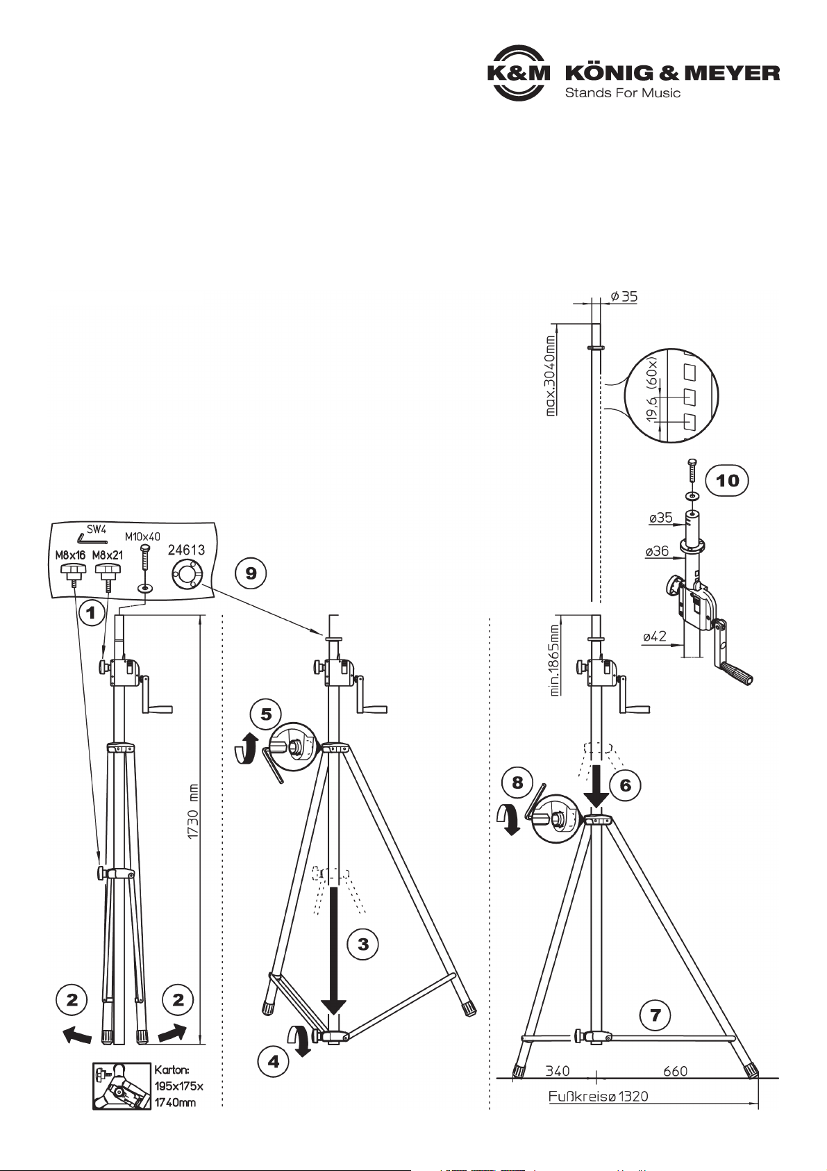
A. STATIV AUFSTELLEN
A. 11 Beide Klemmschrauben locker eindrehen
A. 12 Beine auseinanderziehen
A. 13 Untere Schelle bis zum Anschlag nach unten ziehen
A. 14 Klemmschraube festdrehen
A. 14 BEACHTE:
A. 14 Handkraft genügt; überfestes Anziehen belastet die Bauteile und ist zu vermeiden
A. 15 Inbusschraube in oberer Schelle mittels beigefügtem Inbusschlüssel leicht lösen
A. 16 Obere Schelle jetzt soweit nach unten schieben bis ...
A. 17 ...Verbindungsstreben waagerecht stehen.
A. 18 Inbusschraube mittels Schlüssel wieder festdrehen.
A. 19 Montage der Abspannscheibe (siehe Anleitung 24613)
A. 10 Funktion der Sechskantschraube (siehe Kap. B, K&M-Traverse 21390)
Vielen Dank, dass Sie sich für dieses Produkt entschieden haben. Diese Anleitung informiert Sie über alle wichtigen Schritte bei Aufbau
und Handhabung. Wir empfehlen, sie auch für den späteren Gebrauch aufzubewahren.
Vor Aufbau und Benutzung bitte die SICHERHEITSHINWEISE (s.Rückseite) beachten
Page 2
SICHERHEITSHINWEISE
- Max.zentrische Last: 30 kg
- Vor und nach Benutzung Stativ auf Schäden überprüfen. Beschädigte Stative dürfen nicht
- weiter eingesetzt werden.
- Stativ darf nicht einseitig belastet werden.
- Der Untergrund muß tragfähig und eben sein.
- Bei unsicheren Verhältnissen (Boden, Wind etc.) empfiehlt sich das Abspannen des
- Stativs; dazu Abspannscheibe 10 nutzen.
- Vor Installation prüfen, ob Stativ, Traglasten und Hilfsmittel (Leitern u.a.) funktionstüchtig sind.
- Auf geeignetes Leuchten-/Boxenmaterial achten; d.h. die Anschlussadapter müssen über die
- richtige Größe und Güte verfügen.
- Unbefugte vom belasteten Stativ fernhalten: Schutz vor Stolperfallen, Kippgefahren.
- Sicherheit der Installation überwachen:
- - auf feste Schraubverbindungen achten,
- - die maximale Standfestigkeit erreicht das Stativ bei waagerecht eingestellten Fußstreben
- - Drucktaste an der Kurbel muss -außer beim Ein- und Ausfahren des Rohres- stets
--eingerastet sein
- ACHTUNG: das Verschieben des belasteten Stativs kann zu Beschädigungen des
- Fußgestells führen
- Aufmerksame Handhabung erforderlich, da die Verstellmöglichkeiten Einklemmgefahren bergen
TECHNISCHE DATEN
KÖNIG & MEYER GmbH & Co. KG
Kiesweg 2, 97877 Wertheim, www.k-m.de
24610-009-55 Rev.10 03-80-638-00 5/15
Material
- Grundrohr, Fußrohre, Streben: Alu
- Auszugrohr, Bolzen, Buchsen: Stahl
- Schellen, Gehäuse: Zink-Druckguß
- Führungen: Polyamid (PA)
- Parkettschoner, Stoßdämpfer: TPE
Traglast - max. 30 kg zentrische Last
Abmessungen
- max. Fußkreis ø 1320 mm
- Höhe: 1865-3040 mm (bei max. Fußkreis)
- Auszugrohr: ø 35 mm mit Buchse M10
Packmaß, kg B x T x H: 175 x 195 x 1730 mm, 8,0 kg
Zubehör (inkl.) - Abspannvorrichtung 24613
Zubehör
(optional)
- Tragetasche 24611
- Traversen 213/9 u. 21393
- Adapter 19580, 19656, 24281 etc.
PRÜFEN, INSTANDHALTEN, REINIGEN
- Schonender Umgang mit dem Stativ erhält die
- Teleskopierbarkeit, die Tragkraft und die
- Sicherheit der Installation.
- Bei Wartungsarbeiten -stets im unbelasteten
- Zustand- auf evtl. Gefährdungen achten
- (Einklemmen, Anstoßen, Kippen).
- Zur Reinigung und Pflege am besten ein leicht
- feuchtes Tuch und ein nicht scheuerndes
- Reinigungsmittel benutzen.
FEHLERSUCHE (F) und BESEITIGUNG (B)
(F): Stativ wackelt
(F): (B): Bodenunebenheiten beseitigen
(F): (B): Fußgestell in max. Auslage bringen und
(F): (B): Klemmschraube anziehen
(F): Auszugrohr wackelt bzw. fährt ein unter Last
(F): (B): Rastbolzen prüfen, Klemmschraube anziehen
BEACHTE
Das Kurbelsystem sorgt für bequemes Aus- und Einfahren der Last.
Jedoch, unterschätzen Sie nicht das Gewicht der Leuchten/Box (max. 30 kg),
welche zunächst auf das Stativrohr gesetzt werden muss,
d.h.: fachlich und körperlich geeignetes Personal ist erforderlich,
was je nach Gewicht auch 2 - 3 Personen bedeuten kann.
C. BEWEGEN
C. DER LAST
Im Gegensatz zu anderen
Stativen kann hier beim
Kurbelstativ eine einzelne
Person den Lautsprecher
bequem und sicher in die
gewünschte Höhe
bewegen.
REIHENFOLGE BEIM
EIN- UND AUSFAHREN
DES LAUTSPRECHERS
BENUTZERHINWEISE / FUNKTIONEN
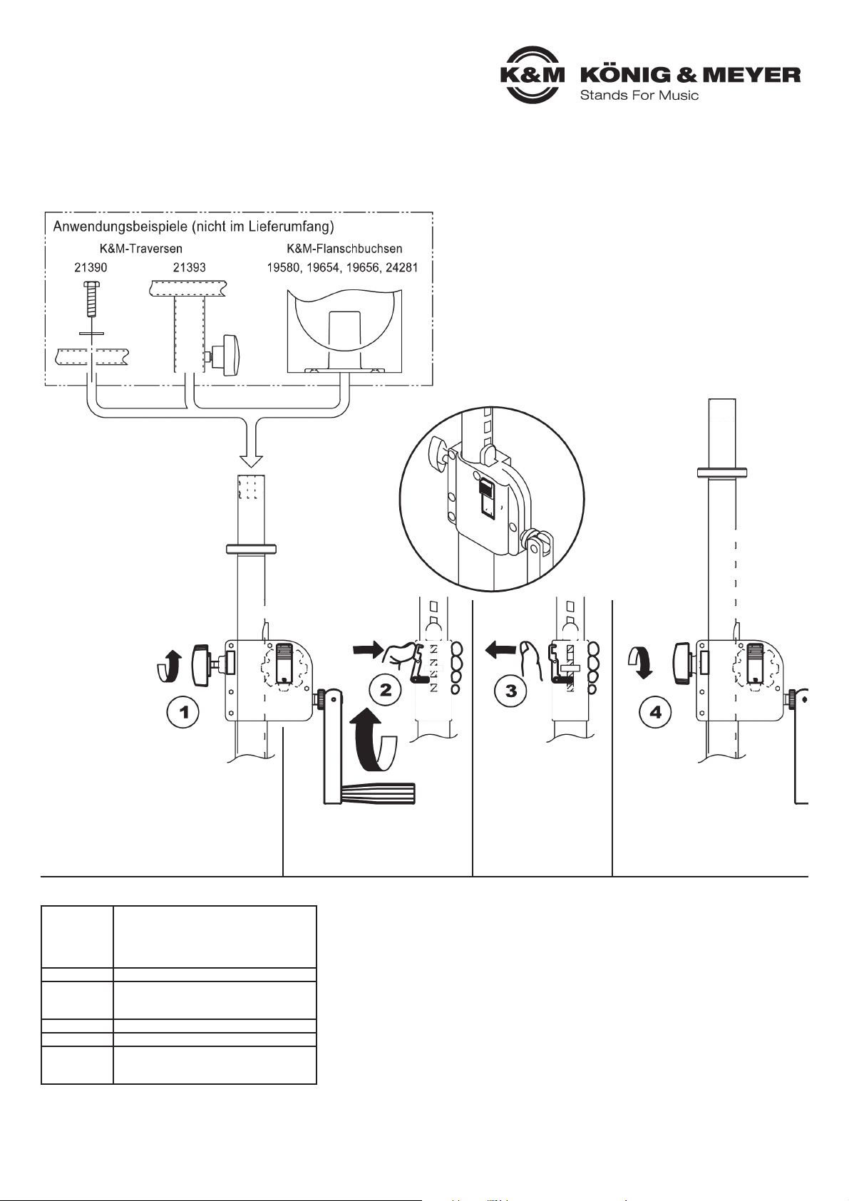
B. AUFBRINGEN und AUSFAHREN
B. der LAST (Traversen, Lautsprecher)
1
Klemmschraube
Lockern
2
Kurbel drehen und Drucktaste
für die Dauer der Kurbelbewegung gedrückt halten
3
Sobald gewünschte
Höhe erreicht ist
Drucktaste los- und
einrasten lassen
- evtl. ist dazu noch
- eine geringe Drehung
- der Kurbel notwendig
4
Klemmschraube
Festdrehen
Page 3

246/1 Lighting/Speaker Stand
- Load Bearing Weight: 30 kg / TÜV Certified-Construction Type / with clamping ring
- High quality stand for professional use: safe, stable and easy to set up
- Similarly adapted for home, property, public area
- Height: min 1865 / max 3040 mm; M10-Screw Socket on the Extension Tube
SET UP INSTRUCTIONS
A. SETUP STAND
A. 11 Screw in both clamp screws loosely
A. 12 Expand the legs
A. 13 Pull the lower bracket arm to the lowest position
A. 14 Tighten the clamp screw
A. 14 ENSURE:
A. 14 Manual strength in sufficient; do not over-tighten - this will negatively affect the
A. 14 components - and should be avoided
A. 15 Loosen the hexagon socket screw in the upper bracket using the hexagon key
A. 16 Push the upper bracket downwards until...
A. 17 ...the connecting struts are level.
A. 18 Use the hexagon key to re-tighten the hexagon socket screw.
A. 19 Assemble the rigging ring (refer to Instructions 24613)
A. 10 Function of the hexagon socket screw (refer to Section B, K&M-Crossbar 21390)
Thank you for choosing this product. The instructions provide directions to all of the important set up and handling steps.
We recommend you keep these instructions for future reference.
Prior to assembly and use please refer to the SAFETY NOTES (located on the back)
Page 4

SAFETY NOTES
- Maximum centric load 30 kg
- Before and after use check stand for damage. Damaged Stands may not be used.
- Weight distribution must not allow the stand to list to one side
- The floor must be load bearing and even.
- In unsafe circumstances (surface, wind etc.) we recommend that the stand be rigged;
- to do this use the clamping ring 10.
- Prior to installation check if the stand load and aids (ladders among other aids) are in working order.
- Ensure use of suitable lighting and speakers; i.e. the connection adapters must be equipped
- with the proper dimensions and quality.
- Keep unauthorized personnel away from the stand. Protect against risk of tripping or the stand
- falling over.
- Maintain safety when installing the system:
- - Ensure the screws are properly tightened.
- - the maximum stability is given when the base struts of the stand are level.
- - The crank button must be in the correct position (has clicked into place) unless the crank is
--being used to extend or retract the tube.
- ENSURE: moving a stand with the speakers attached can result in damaging the stand's base.
- Careful and attentive handling is required when adjusting the stand - due to the possibility of
- pinching or wedging your hand.
TECHNICAL DATA
KÖNIG & MEYER GmbH & Co. KG
Kiesweg 2, 97877 Wertheim, www.k-m.de
24610-009-55 Rev.10 03-80-638-00 5/15
Material
- Base tube, Leg Tubes , Struts: Aluminum
- Extension Tube, Bolts, Connectors: Steel
- Bracket, Housing: zinc-die cast
- Guides: Polyamide (PA)
- End caps, Shock absorbers: TPE
Bearing Load - max. 30 kg centric load
Dimension
- max. surface circle ø 1320 mm
- Height 1865-3040 mm
- Extension tube: ø 35 mm M10 socket
Package, kg W x D x H: 175 x 195 x 1730 mm, 8,0 kg
Accessories - Rigging 24613
Accessories
(optional)
- Carrying Case 24611
- Crossbars 213/9 a. 21393
- Adapter 19580, 19656, 24281 etc.
CHECK, MAINTENANCE, CLEANING
- Careful use of the stand maintains the use of the
- telescope and the load bearing functionality of the
- stand, as well as the safety of the installation
- Perform workstation maintenance only without the
- lighting/speakers attached and watch for possible
- risks (pinching, the stand is bumped or falls over)
- To care for the product use a damp cloth and a non-
- abrasive cleaning agent.
FAULT-FINDING (F) and REPAIR (R)
(F): Stand is not stable
(F): (B): Ensure that the surface is even
(F): (B): Ensure that the base is expanded to its full
(F): (B): expanded position and tighten the clamp screw
(F): The extension tube is loose i.e. retracts when the
(F): speakers are attached
(F): (B): Check if the button on the crank is in the
(F): (B): correct position (has clicked into place) and
(F): (B): tighten the clamp screw
ENSURE
The crank system is used for easy extension and retraction of the speakers
(load). However, do not underestimate the weight of the lighting/speakers
(max. 30 kg), which must be placed on the stand tube,
i.e.: knowledgeable and physically fit individuals are needed,
depending on the load weight – this can require 2 - 3 individuals.
C. MOVEMENT
C. OF THE LOAD
In contrast to other stands
one individual is able to
move the speakers to the
desired height by simply
using the crank system.
SEQUENCE WHEN
EXTENDING AND
RETRACTING
THE SPEAKERS
USER INFORMATION / FUNCTIONS
B. PLACEMENT and EXTENSION
B. of the LOAD (Crossbars, Speakers)
1
Loosen the
clamp screw
2
Turn the crank and keep
the button pushed while
turning the crank handle
3
As soon as the desired
height has been
reached release the
button and in some
cases a half of a turn
of the crank is still
required
4
Tighten
the clamp screw
Application Examples (not included in the delivery)
K&M-Crossbars
K&M-Flange Adapters
 Loading...