

Page 1

- Traglast: Mikrofone
- Das Hantieren mit einer Mikrofonangel bedeutet eine nicht unerhebliche Gefährdung für:
- a. Bediener, b. Personen und c. Gegenstände in Reichweite (Aufbauten, Lampen etc.).
- Entsprechend vorsichtige Handhabung ist unbedingt erforderlich.
- Wir warnen insbesondere vor den Gefahren durch Blitzschläge und Stromkabel.
- Auch eine nicht unmittelbar benutzte Mikrofonangel kann sich als Gefahrenquelle erweisen,
- z.B. als Stolperfalle, wenn sie unsachgemäß abgelegt wurde. Nach Gebrauch sollte die Rohr-
- kombination unverzüglich eingefahren und sicher aufbewahrt werden.
- Um unbeabsichtigtes Aus- bzw. Einfahren der Rohre zu verhindern, wird stets nur ein Klemmelement
- geöffnet und das entsprechende Rohr bedient.
- Bei Gebrauch, Transport und Lagerung müssen sämtliche Klemmelemente geschlossen sein.
- Bei Verwendung eines innen verlaufenden Kabels darauf achten, dass dieses an den Kabelöffnungen
- nicht beschädigt wird. Im Lieferumfang ist keine Verkabelung enthalten.
- Da nur ein Teil der Nutzer mit Kabel arbeitet ist die Gummikappe nicht durchgelocht; bei Bedarf die
- dünne Wandung (ø 12 mm) ausschneiden. ACHTUNG vor Schnittverletzungen schützen.
- Der Bediener muss in der Lage sein mit der Mikrofonangel verantwortlich umgehen zu können.
- Das Mikrofon stets erst nach dem Ausfahren anbringen - und vor dem Einfahren wieder abnehmen.
- Die Carbonrohre zeichnen sich u.a. aus durch Festigkeit und Steifheit. Dennoch kann Mißbrauch und
- Gewalt zu Schäden an den Rohren führen. Beschädigte Rohre dürfen auf keinen Fall benutzt werden, weil:
- a. eventuelle scharfe Kanten zu schmerzhaften Verletzungen bei Bedienern oder Dritten führen können,
- b. die einwandfreie Funktion nicht mehr gewährleistet werden kann.
- Die Mikrofonangel ist komplett vormontiert und sofort einsatzbereit.
- Das Material Carbon vereint große Festigkeit und Steifigkeit mit geringem Gewicht
- Kabelöffnungen ermöglichen den Einsatz eines im Inneren der Angel verlaufenden Kabels
- Eine Grundregel lautet: beim Aufbau der Mikrofonangel ist das Anbringen des Mikrofons
- der letzte Arbeitsgang - beim Abbau der Erste.
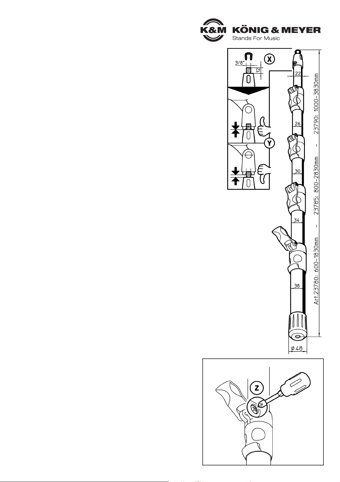
- Das 3/8"-Mikrofonanschlußgewinde ist durch eine Gummikappe (siehe X) geschützt.
- Wir empfehlen diese nach Gebrauch immer wieder aufzubringen.
- Das Mikrofon bzw. die Mikrofonhalterung (siehe Y) stets bis zum Anschlag auf das 3/8”-
- Gewinde aufschrauben. Dies ist aus zwei Gründen wichtig:
- 1. Das Mikrofon sitz fest auf dem Gewinde und verdreht sich nicht.
- 2. Das Gewinde ist geschützt vor Biegekräften und Beschädigungen durch Schmutz und Abrasion.
- Die Gängigkeit der Klemmhebel kann individuell eingestellt werden (siehe Z).
Vielen Dank, dass Sie sich für dieses Produkt entschieden haben. Diese Anleitung informiert Sie über alle
wichtigen Schritte bei Aufbau und Handhabung. Wir empfehlen, sie auch für den späteren Gebrauch
aufzubewahren.
KÖNIG & MEYER GmbH & Co. KG
Kiesweg 2, 97877 Wertheim, www.k-m.de
23780-000-55 Rev.04 23785-000-55 Rev.04 23790-000-55 Rev.03 03-80-325-00 8/15
23780/85/90 Mikrofonangel
- Zur manuellen Positionierung von Mikrofonen über Entfernungen
- bis zu 1,8 m / 2,8 m / 3,8 m
- Optisch, technisch und in der Handhabung absolut auf der Höhe der Zeit
- Extrem leichte und dabei höchst steife 5-fach Rohrkombination aus Carbonfasern
- Ein Mikrofonkabel (max. ø 6 mm) kann im Inneren der Rohre platziert werden
- Ideal für den mobilen Einsatz: leicht und klein zusammenlegbar; inkl. gepolsterte Tasche
- Hervorragende Handhabung und Bedienung durch effektive Klemmelemente: Klemm-
- kraft individuell justierbar; geräuscharmes Aus-/ Einfahren der Rohre; kein Klappern
- Länge stufenlos einstellbar von 600-1830 mm, 800-2830 mm, 1000-3830 mm;
- Gewindeanschluss: 3/8"
SICHERHEITS- und HANDHABUNGSHINWEISE
HINWEISE FÜR DEN BENUTZER
- Im Lieferumfang enthalten ist eine exakt passende und gepolsterte Umhängetasche.
- Bei Bedarf finden Sie im Programm von KÖNIG & MEYER Mikrofonklammern unterschiedlicher
- Größe, welche auf das Anschlussgewinde der Mikrofonangel aufgeschraubt werden können:
- Mikrofonklammer Art.-Nr. 85035: für Mikrofongrößen ø 17 - 22 mm,
- Mikrofonklammer Art.-Nr. 85050: für Mikrofongrößen ø 22 - 28 mm,
- Mikrofonklammer Art.-Nr. 85055: für Mikrofongrößen ø 28 - 34 mm,
- Mikrofonklammer Art.-Nr. 85060: für Mikrofongrößen ø 34 - 40 mm (konisch),
- Mikrofonklammer Art.-Nr. 85070: für Mikrofongrößen ø 34 - 40 mm (parallel)
ZUBEHÖR
F: Rohre lassen sich nicht oder nur schwer ausfahren
F: B: ACHTUNG: Verletzungsgefahr falls Rohre beschädigt sind.
F: B: In diesem Falle K&M kontaktieren.
F: B: Klemmhebel vollständig öffnen, nur dann ist eine leichtgängige
F: B: Verstellung möglich (siehe Z).
F: B: Klemmkraft der Spannhebel neu justieren
F: B: Rohre reinigen
F: Rohre lassen sich nicht richtig festklemmen
F: B: Klemmkraft der Spannhebel neu justieren
F: Kabel stellt sich beim Einfahren der Rohre "quer"
F: B: Kabel an der Grundrohröffnung fassen und sanft ziehen bis Rohre einfahren
FEHLERSUCHE (F) und BESEITIGUNG (B)
KLEMMHEBEL JUSTIEREN
KreuzschlitzSchraubendreher
ansetzen und
Schraube je nach
Bedarf öffnen
oder lockern oft genügt dazu
der Bruchteil einer
Umdrehung.
Page 2

TECHNISCHE DATEN
Material
- Teleskoprohre: Carbonfaser
- Klemmelemente: Polyamid PA-6
- Grundrohr Kappe: Elastomer TPE
- Mikrofongewinde: Aluminium
Tasche
mit Reißverschluss, Umhängeschlaufe mit Karabinerhaken,
gepolstert
Rohrkombination: 5-fach, ø 38 - 34 - 30 - 26 - 22 mm
Gewindeanschluß Mikrofon: 3/8" x 12 mm
Kabel, wenn innen verlaufend: max. ø 6 mm (1/4")
23780 – kurz 23785 – mittel 23790 – lang
Reichweite 600 - 1830 mm 800 - 2830 mm 1000 - 3830 mm
Packmaß 6 x 48 x 610 mm 6 x 48 x 810 mm 6 x 48 x 1010 mm
Gewicht 0,58 kg 0,74 kg 0,9 kg
Tasche
ø 80 x 660 mm
0,15 kg
ø 80 x 860 mm
0,2 kg
ø 80 x 1060 mm
0,25 kg
A.a. KABELMONTAGE
- erfolgt im ausgefahrenen Zustand der Rohrkombination
- Kabel um ausgefahrene Rohre wickeln und sichern (z.B. Klebeband)
A.b. ROHRE AUSFAHREN
1 Einen Klemmhebel öffnen:
1 1.a teilweises Öffnen für zähgängige Verstellung der Rohre
1 1.b komplettes Öffnen für leichtgängige Verstellung der Rohre
2 Rohr so weit wie gewünscht ausfahren,
3 Klemmhebel wieder schließen (muss an der Schelle anliegen)
BEACHTE: niemals sämtliche Klemmhebel auf einmal öffnen 5,
sondern den Vorgang 1-3 für jeden Klemmhebel der Reihe nach durchführen.
A.c. ROHRE EINFAHREN
- zuerst Mikrofon abschrauben bzw. aus Klammer entfernen,
- anschließend das Kabel entfernen/aufwickeln
- nun einen Klemmhebel öffnen, das Rohr einfahren, Klemmhebel schließen
- diesen Vorgang auch bei den anderen Klemmhebeln durchführen 5
A Handhabung - mit außen verlaufendem Kabel / ohne Kabel
B.a. KABELMONTAGE
- erfolgt im eingefahrenen Zustand der Rohrkombination
4 Grundrohrkappe abziehen und Gummihaut entfernen 4.a.
5 Kabel in die obere Öffnung (am Mikrofon) einführen und durchschieben...
6 ...bis es am Grundrohr auftaucht und vorsichtig durchgezogen werden kann.
7 Dabei das Kabel an der oberen Öffnung behutsam nachführen.
8 Kabel unten durch Grundrohrkappe schieben.
9 Grundrohrkappe wieder auf das Rohr aufpressen.
- Nach erfolgter Montage sollte das Kabel an der oberen Öffnung (am Mikrofon)
- gegen ungewolltes Einziehen sowie Druck- und Knickstellen gesichert werden.
- Dazu an das Kabel angepasste Zugentlaster oder geeignetes Klebeband benutzen.
B.b. ROHRE AUSFAHREN
siehe A.b
B.c. ROHRE EINFAHREN
- zuerst Mikrofon abschrauben bzw. aus Klammer entfernen,
- danach einen Klemmhebel komplett öffnen 1.b
- Kabel an der unteren Kabelöffnung fassen und sanft ziehen, bis das Rohr
- eingefahren ist (bei Bedarf am Rohr direkt nachfassen),
- BEACHTE!
- Das Kabel darf dabei an der oberen Öffnung nicht gequetscht werden
- Klemmhebel wieder schließen.
- diesen Vorgang auch bei den anderen Rohren durchführen.
- Kabel aufrollen und sichern.
B Handhabung - mit innen verlaufendem Kabel
Zur Reinigung ein leicht feuchtes Tuch und ein nicht scheuerndes Mittel benutzen.
PRÜFEN, INSTANDHALTEN, REINIGEN
A.b / B.b
ROHRE AUSFAHREN
KABELMONTAGE
B.a
Page 3
- Load bearing weight: Microphone
- The handling of a fishing pole microphone can bear significant risks for: a. operator, b. persons and
- c. objects within reach (structures, lamps etc.). Careful handling is indispensable.
- We especially warn against the risks associated with lightening and electrical cables.
- Other fishing pole microphones that are nearby may also be a source of danger,
- e.g. the risk of tripping if it is not properly stowed. After use, the tube combination should be retracted
- and securely stored away immediately.
- To avoid the unintended extension or retraction of the tube, only one clamp element is always in the
- open position and the tube can be extended or retracted.
- All clamping elements must be in a closed position during use, transport and storage.
- When using an internal cable, please ensure that the cable opening is not damaged. Cable is not included
- with the delivery. Because only a segment of the users work with cables, the rubber cap does not come
- with a hole in it, if needed cut a hole into the thin wall (ø 12 mm) of the cap.
- NOTE: Please protect yourself from the risk of cuts.
- The operator must be able to use the fishing pole microphone in a responsible manner.
- Attach the microphone after the tube has been extended - and remove the microphone prior to retracting the tube.
- The carbon tubes are very strong and sturdy. However, improper use and excessive force can result in
- damage to the tubes. Damaged tubes may not be used in any case, because:
- a. possible sharp edges can result in painful injuries for the operators or third parties,
- b. the perfect functioning of the pole is no longer guaranteed.
- The fishing pole microphone comes pre-assembled and can be used at once.
- The carbon material unifies strength and sturdiness at a minimal weight.
- The cable opening provides for the use of a cable that is threaded inside the tube.
- A basic rule states that when setting up the fishing pole microphone - attach the microphone as a last step -
- and when putting it away removing the microphone is a first step.
- The 3/8" microphone threaded connector is protected by a rubber cap (see X).
- We recommend that the cap is placed on the threaded connector after each use.
- Screw on the microphone i.e. the microphone holder (see Y) onto the 3/8" threaded bolt as far as it will go. -
- This is important for two reasons:
- 1. The microphone sits snuggly on the threaded bolt and does not twist out of position.
- 2. The threaded bolt is protected against bending forces and damage caused by dirt and abrasion.
- The variable clamp lever can be adjusted individually (see Z).
Thank you for choosing this product. The instructions provide directions to all of the important set up
and handling steps. We recommend you keep these instructions for future reference.
KÖNIG & MEYER GmbH & Co. KG
Kiesweg 2, 97877 Wertheim, www.k-m.de
23780-000-55 Rev.04 23785-000-55 Rev.04 23790-000-55 Rev.03 03-80-325-00 8/15
23780/85/90 Microphone
»Fishing Pole«
- For manual positioning of microphones over distances of up to 1.8 m / 2.8 m / 3.8 m
- This pole is leading edge both in appearance, technically and as far handling
- is concerned
- Extremely light, very strong and sturdy 5 tube combination made out of carbon fiber
- A microphone cable (max. ø 6 mm) can be placed inside the tube
- Ideal for mobile use: it is light and collapsible to a small size, incl. cushioned carrying case
- Excellent handling and use through effective clamp elements: Clamp strength can
- be individually adjusted; quiet telescoping in/out of the tube; it doesn't rattle
- Long variable adjustment from 600-1830 mm, 800-2830 mm, 1000-3830 mm;
- Threaded Connector: 3/8"
SAFETY and HANDLING and USAGE NOTES
OPERATOR NOTES
- Included with the delivery is a shoulder bag that is cushioned and fits the pole perfectly.
- If needed you can purchase different sizes of KÖNIG & MEYER microphone clamps, that can be
- screwed onto the connector thread of the fishing pole microphone:
- Microphone Clamp No. 85035: microphone size ø 17 - 22 mm,
- Microphone Clamp No. 85050: microphone size ø 22 - 28 mm,
- Microphone Clamp No. 85055: microphone size ø 28 - 34 mm,
- Microphone Clamp No. 85060: microphone size ø 34 - 40 mm (cone form),
- Microphone Clamp No. 85070: microphone size ø 34 - 40 mm (parallel)
ACCESSORIES
F: The tubes are difficult to extend
F: R: NOTE: Risk of injury if the tubes are damaged. In this case contact K&M.
F: R: Open the clamp handle as far as it goes, only then can it be set easily
F: R: adjusted (see Z).
F: R: Re-adjust the clamp lever
F: R: Clean the tubes
F: The tubes cannot be properly put together
F: R: Re-adjust the clamp lever
F: The cable does not cooperate when retracting the tubes
F: R: Hold the cable at the base tube opening and pull without any force to retract the tube
FAULT-FINDING (F) and REPAIR (R)
ADJUST THE CLAMP LEVER
Use Phillips
Screwdriver
and unscrew the
screw as needed
or loosen -a fraction
of a turn - is usually
enough.
Page 4

TECHNICAL DATA
Material
- Telescope rods: Carbon fiber
- Clamp elements: Polyamid PA-6
- Base tube cap: Elastomer TPE
- Microphone thread: Aluminum
Carry case with zipper, shoulder strap with carabiner hooks, cushioned
Rod combination: quintuplicate, ø 38 - 34 - 30 - 26 - 22 mm
Microphone connector thread: 3/8" x 12 mm
Cable, if internal: max. ø 6 mm (1/4")
23780 – short 23785 – medium 23790 – long
Range 600 - 1830 mm 800 - 2830 mm 1000 - 3830 mm
Packing size 6 x 48 x 610 mm 6 x 48 x 810 mm 6 x 48 x 1010 mm
Weight 0.58 kg 0.74 kg 0.9 kg
Carry case
ø 80 x 660 mm
0.15 kg
ø 80 x 860 mm
0.2 kg
ø 80 x 1060 mm
0.25 kg
A.b / B.b
EXTEND THE TUBES
CABLE ASSEMBLY
B.a
A.a. CABLE ASSEMBLY
- is done when the tube combination is fully extended
- wrap the cable around the tube combination and secure it (e.g. with tape)
A.b. EXTEND THE TUBES
1 Open a clamp lever:
1 1.a open a bit when it is difficult to adjust the tubes
1 1.b open completely when it is easy to adjust the tubes
2 Extend the tube as far as desired,
3 Close the clamp lever (must touch the bracket)
NOTE: Never open all clamp levers at once 5,
but repeat steps 1-3 for each clamp lever one after the other.
A.c. RETRACT TUBES
- first unscrew the microphone i.e. remove it from the clamp
- then remove/wind up the cable
- now open the clamp lever, retract the tube, close the clamp lever
- repeat these steps with the other clamp levers 5
A Handling - with a cable that is exposed / without cable
B.a. CABLE ASSEMBLY
- is done when the tube combination is fully retracted
4 Remove the base tube cap and remove the rubber skin 4.a.
5 Thread the cable through the upper opening (on the microphone) and push the
cable through...
6 ...until it shows up at the base tube - and can be carefully pulled through.
7 In the process carefully push the cable through the upper opening.
8 Push the cable through the base tube cap.
9 Place the base tube cap back on the tube.
- After the assembly is complete ensure that the cable at the upper opening
- (Microphone) is secured against being pulled involuntarily and against bending
- the cable. For this please use a strain reliever or suitable tape.
B.b. EXTEND THE TUBES
see A.b.
B.c. RETRACT TUBES
- first unscrew the microphone i.e. remove it from the clamp
- then completely open the clamp lever 1.b
- Hold the cable at the lower cable opening and pull without any force to retract
- the tube (if needed pull on the tube itself).
- NOTE: The cable may not be crushed in the upper opening.
- Close the clamp lever
- Repeat these steps with the other tubes.
- Wind up the cable and store it.
B Handling - for internal cable
To care for the product use a damp cloth and a non-abrasive cleaning agent.
CHECK, MAINTENANCE, CLEANING
 Loading...