

Page 1
SICHERHEITSHINWEISE
TECHNISCHE DATEN / SPEZIFIKATIONEN
Vielen Dank, dass Sie sich für dieses Produkt entschieden haben. Diese Anleitung informiert
Sie über alle wichtigen Schritte bei Aufbau und Handhabung.
Wir empfehlen, sie auch für den späteren Gebrauch aufzubewahren.
A. MAXIMALE TRAGLAST
Die maximale Traglast des Distanzrohrs beträgt 35 kg bei zentrischer Belastung.
Diese kann bei ungünstigen Bedingungen (Bodenuneben-heiten, Seitenwinden etc.)
abweichen und deutlich unter den 35 kg liegen.
Speziell bei der Verwendung des Distanzrohrs mit einer Befestigungsplatte (z.B.
K&M 24116) kann von unserer Seite keine Angabe zur maximalen Traglast gegeben
werden, da diese von der jeweiligen Boxen-/Satellitenkombination abhängig ist. Für
daraus entstehende Schäden übernehmen wir keine Haftung. Bitte beachten
Sie hierzu auch die jeweiligen landesrechtlichen Sicherheitsbestimmungen,
z.B. für öffentliche Veranstaltungen. Bei Fragen zu Sicherheitshinweisen
und rechtlichen Bestimmungen kontaktieren Sie bitte Ihren Fachhändler.
B. ALLGEMEIN
- Montage und Handhabung nur durch geeignetes Personal (2 fachlich und
- körperlich geeignete Personen)
- Vor der Installation prüfen, ob das Stativ oder die Box (v.a. Größe und Güte der
- Flanschbuchse) sowie Hilfsmittel (z.B. Leitern) funktionstüchtig sind.
- Bei Montagearbeiten Schutzhandschuhe tragen
- Verwendung nur im Innenbereich
- Auf geeigneten, d.h. ebenen und tragfähigen Untergrund achten
- ACHTUNG! Die Basis (z.B. Platte) ist schwer und stellt bei unsachgemäßer
- Handhabung eine Gefährdung für Personen und Sachen dar.
- BEACHTE: Insbesondere bei der Montage nicht fallen lassen; Quetschgefahr
C. AUFBAU, BETRIEB, DEMONTAGE
AUFBAU: Schraubverbindung zwischen Stativrohr und Sockelplatte
muss stets bis zum Anschlag angezogen sein 5.a
- Festigkeit dieser Verbindung ist regelmäßig zu prüfen
BETRIEB: Rohrkombination immer zentrisch belasten:
- außermittige Lasten beeinträchtigen die Standfestigkeit und somit auch
- maßgeblich die Traglast!
- Drucktaster 8 muss sich stets im Eingriff befinden und die Sicherungs-
- schraube 9 angezogen sein
- Niemals Drucktaster und Sicherungsschraube unkontrolliert lösen, d.h.
- das Auszugrohr muss in diesem Falle stets von einer geeigneten Person
- festgehalten werden
DEMONTAGE: Erst Traglast vom Auszugrohr entfernen und danach das
Stativrohr aus der Sockelplatte herausdrehen
D. SEITENKRÄFTE
- Seitenkräfte sind wegen der Kippgefährdung unbedingt zu vermeiden.
- Sie entstehen (oft unabsichtlich) durch:
- a. außermittigen Schwerpunkt der Traglast
- b. Stöße, Berührungen, Erschütterungen, Wind, unebener Boden
- c. den Versuch das belastete Stativ zu verschieben
- BEACHTE: Sicherheitsabstände einhalten, Unbefugte fernhalten
- Falls die Wirksamkeit dieser Maßnahmen nicht garantiert werden kann,
- (z.B. durch unkontrollierbare Nichteinhaltung des Sicherheitsabstandes)
- sind durch den Aufsteller zusätzliche Sicherungen vorzunehmen, z.B.:
- - Verankerung/Erweiterung/Beschwerung der Sockelplatte
- - Zusätzliche Abstützung der Rohrkombination
- - Unbedingt auf fest eingeschraubtes Grundrohr achten 5.a
AUFBAUANLEITUNG
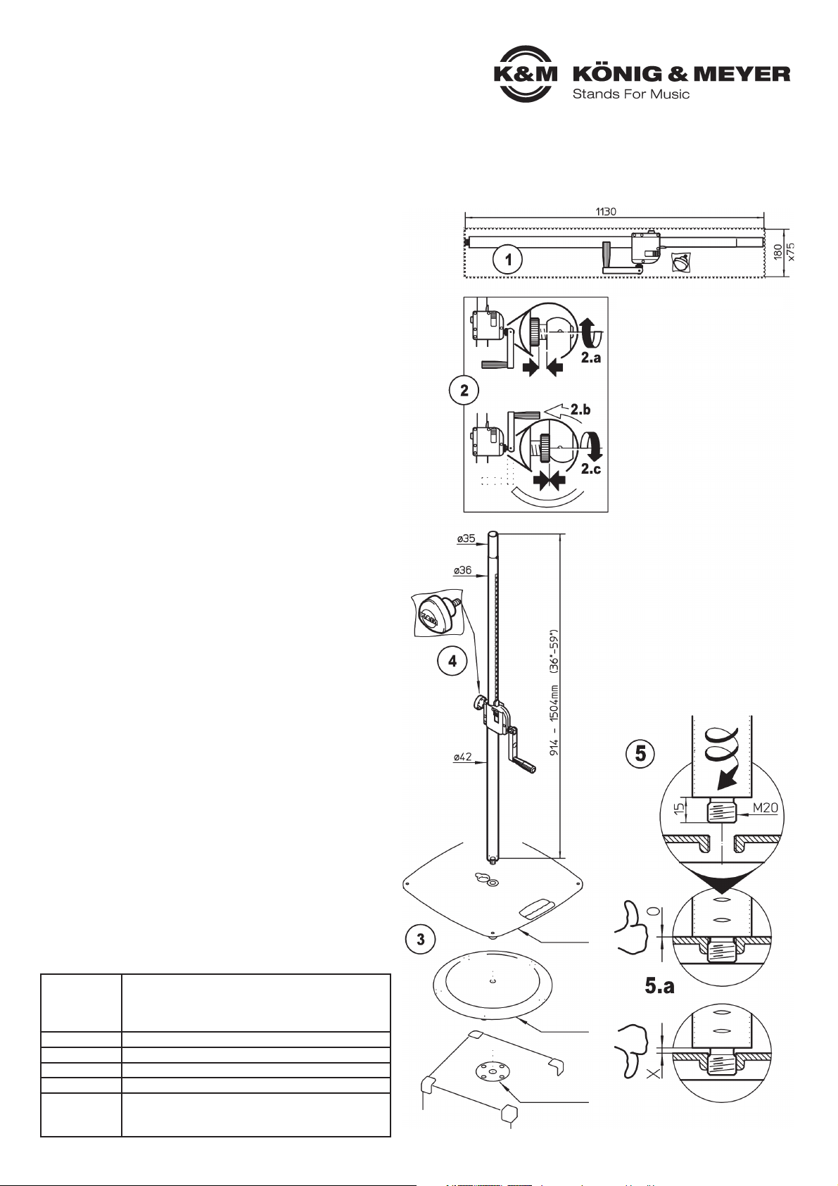
1 Distanzrohr aus Karton
1 entnehmen
2 Kurbel aus Transportstellung
2 lösen und in Bedienstellung
2 bringen:
Dazu:
2.a Stellring bis zum Anschlag in
2.a Richtung Kurbelgehäuse drehen
2.b Kurbel um 180° herausklappen
2.c Stellring nun wieder bis zum
2.c Anschlag an die Kurbel drehen
3 Basis (Bodenplatte, Subwoofer etc.)
3 an geeigneter Stelle auslegen.
4 Sicherungsschraube in Spann-
4 schelle eindrehen und fest an-
4 ziehen (Handkraft genügt)
5 Gewinde-M20 der Rohrkombination
5 bis zum Anschlag fest in die Basis
5 einschrauben.
5.a Zwischen Rohr und Platte darf
5.a sich kein Luftspalt befinden.
5.a BEACHTE:
5.a Verschraubung regelmäßig
5.a prüfen und ggf. nachziehen.
21339 Distanzrohr
mit Kurbel
- Höhenverstellbares Distanzrohr zur Verwendung mit Boden- oder Befestigungsplatten für Boxen-/Satelittensysteme
- Mehrfach gesichert durch Kurbelgetriebe, Drucktaste, Klemmschraube
- Höhe: min. 914 / max. 1504 mm; Auszug: ø 35 mm; Gewindeanschluss: M20; Gewicht: 4,0 kg
Material
Rohre: Stahl, schwarz gepulvert
Schrauben, Bolzen: Stahl verzinkt
Kurbelgehäuse: Zink-Druckguß
Griffe: PA
Traglast max. 35 kg zentrische Last
Abmessungen Höhe: min. 914 - max. 1504 mm
Karton L x H x B: 1130 x 180 x 75 mm
Gewicht netto: 4,0 kg, brutto : 4,4 kg
Zubehör
(optional)
K&M-Flanschbuchsen (z.B. 19580, 19654, 19656)
Anschraubflansch (24281)
Adapterhülse 21326: ø 38 mm (=US-Variante)
Sockelplatte
- K&M 26705
Rundsockel
- K&M 26700
Befestigungsplatte
- K&M 24116
Page 2
FEHLERSUCHE (F) und BESEITIGUNG (B)
F: Basis kippelt auf dem Boden: B: Untergrund auf Ebenheit prüfen
B: Basis (Platte/Subwoofer) auf Ebenheit prüfen
B: Filzschoner vorhanden?
F: Distanzrohr wackelt/steht schief: B: Festen Sitz der M20-Gewinde prüfen
B: und ggf. Rohrkombination fest eindrehen 5
B: Rohrkombination auf Geradheit prüfen
B: Für ebenen Untergrund sorgen
B: Verhältnis von Subwoofer und Satellit ok?
F: Auszugrohr wackelt/fährt ein: B: Sicherungsschraube 9 anziehen
B: Drucktaster 8 prüfen ob eingerastet
KÖNIG & MEYER GmbH & Co. KG
Kiesweg 2, 97877 Wertheim, www.k-m.de
21339-000-55 Rev.10 03-80-871-00 6/16
LAUTSPRECHER AUFBRINGEN und AUSFAHREN
ACHTUNG!
Das Kurbelsystem sorgt für bequemes Aus- und Einfahren der Last.
Jedoch, unterschätzen Sie nicht das Gewicht der Box, welche zunächst auf das Stativrohr gesetzt werden muss,
d.h.: fachlich und körperlich geeignetes Personal ist erforderlich, was je nach Gewicht auch 2 - 3 Personen bedeuten kann.
PRÜFEN, INSTANDHALTEN, REINIGEN
DAS BEWEGEN DER LAST
Im Gegensatz zu anderen
Stativen kann hier beim
Kurbelstativ eine einzelne
Person den Lautsprecher
bequem und sicher in die
gewünschte Höhe bewegen.
REIHENFOLGE BEIM
EIN- UND AUSFAHREN
DES LAUTSPRECHERS
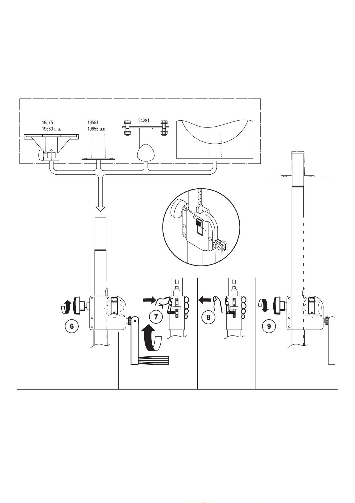
6
Klemmschraube
lockern
7
Kurbel fassen und Drucktaste für
die Dauer der Kurbelbewegung
gedrückt halten
8
Sobald gewünschte
Höhe erreicht ist
Drucktaste loslassen
und einrasten lassen
-evtl. ist dazu noch
eine geringe Drehung
der Kurbel notwendig
9
Klemmschraube
festdrehen
Anwendungsbeispiele (nicht im Lieferumfang)
- Schonender Umgang mit dem Distanzrohr erhält
- die Teleskopierbarkeit, die Tragkraft und
- die Sicherheit der Installation
- Bei Wartungsarbeiten -stets im unbelasteten
- Zustand- auf evtl. Gefährdungen achten
- (Einklemmen, Anstoßen, Kippen)
- Zur Reinigung und Pflege am besten ein leicht
- feuchtes Tuch und ein nicht scheuerndes
- Reinigungsmittel benutzen
Page 3

SAFETY NOTES
TECHNICAL DATA / SPECIFICATIONS
Thank you for choosing this product. The instructions provide directions to all of the
important setup and handling steps. We recommend you keep these instructions for
future reference.
A. MAXIMUM WEIGHT BEARING LOAD
The maximum weight bearing load for the distance rod is 35 kg when the equipment
load is centered. This can deviate in the case of unfavorable conditions (uneven
surfaces, cross winds etc.) and be significantly less than 35 kg.
Specifically, in the case of using the distance rod in connection with a connector plate
(e.g. K&M 24116) we are unable to provide information on the maximum weight
bearing load, because this is determined by the respective loudspeaker/satellite
combination. We will not assume any liability for damages arising from such use.
Please note the respective country-specific safety regulations, like e.g. for
public events. Please contact your retailer with any questions pertaining to
safety or statutory provisions.
B. GENERAL
- Assembly and handling only by qualified technicians (we recommend
- 2 technicians that are physically fit)
- Prior to installation check if the stand, loudspeaker (particularly the size and quality
- of the flange adapter), as well as aids (e.g. ladders) are in working order.
- Wear protective gloves during assembly
- Only to be used indoors
- Be sure that the surface will bear the load and is suitable and level
- ATTENTION! The base plate is very heavy and improper use can result in risk to
- individuals and objects.
- NOTE: In particular do not drop during assembly; risk of pinching or wedging of
- extremities
C. SETUP, OPERATION, DISASSEMBLY
SETUP: The screw connection between the stand tube and the base plate
must be screwed in as far as it will go 5.a
- Routinely check that the screws are properly tightened
OPERATION: The weight tube combination must be centered at all times:
- Off-center loads have a negative effect on stability and in turn on the
- weight bearing load!
- Pushbutton 8 must be locked into place and the locking screw 9
- must be tightened
- Never loosen the pushbutton and the locking screw without
- having someone hold the equipment
DISASSEMBLY: First remove the objects from the extension tube then
unscrew the the stand tube from the base plate
D. LATERAL FORCES
- Lateral forces are to be avoided due to the risk of it falling over.
- The lateral forces are the result of (often unintentionally):
- a. the load bearing weight not being centered
- b. bumping or brushing into the equipment, vibrations, wind, uneven surface
- c. the attempt to move the loaded stand
- NOTE: Maintain safety distance, keep unauthorized persons away
- Should the effectiveness of the measures not be guaranteed, (e.g. through
- the safety distance not being kept and not being checked) the technicians
- should secure the object e.g. with the following additional steps:
- - anchor/expand/weighting down of the base plate
- - additional support of the tube combination
- - ensure that the base tube is screwed in tightly 5.a
SET UP INSTRUCTIONS
1 Take the distance rod out of the box
2 Loosen the crank from the
2 transport position and bring in
2 operating position:
For that purpose:
2.a Turn adjusting ring towards
2.a crankcase until it stops
2.b Fold out crank 180°
2.c Now tighten adjusting ring until
2.c it stops at the crank again
3 Ensure the base (base plate,
3 subwoofer etc.) is placed in the
3 proper position.
4 Screw the locking screw into
4 crankcase and tighten
4 (manual strength is enough)
5 Screw in the threaded connector
5 M20 of the tube combination into
5 the base as far as it will go.
5.a Ensure that a space is not left
5.a between the tube and the plate.
5.a NOTE:
5.a Check the connections (screws)
5.a regularly and tighten, if needed.
21339 Distance rod
with hand crank
- Height adjustable distance rod for use with base/floor plates or conntector plates for loudspeakers/satellite systems
- Multiple security with push-button system, hand crank and locking screw
- Height min. 914 / max. 1504 mm, extension diameter 35 mm, threaded bolt M20, weight: 4.0 kg
Material
Tubes: Steel, black powder coating
Screws, bolt: Steel, galvanized
Crankcase: Zinc-die cast
Handles: PA
Load maximum 35 kg (centered load)
Dimensions Height: min. 914 - max. 1504 mm
Box L x H x W: 1130 x 180 x 75 mm
Weight net: 4.0 kg, gross: 4.4 kg
Accessories
(optional)
K&M-flange adaptor (z.B. 19580, 19654, 19656)
K&M-screw-on-adaptor (24281)
K&M-sleeve adaptor 21326: ø 38 mm
Base plate
- K&M 26705
Round base
- K&M 26700
Connector plate
- K&M 24116
Page 4

FAULT-FINDING (F) and REPAIR (R)
F: The base plate rocks back R: Check if the surface is even
F: and forth on the floor: R: Check the base plate (plate/subwoofer) to
R: ensure that it is on an even surface
R: Are the felt protectors installed?
F: Distance rod is not stable/leaning R: Check the M20 connector is tight, screw it
F: to one side: R: into the tube combination as far as it will go 5
R: Check to ensure the tube combination is straight
R: Ensure that the surface is even
R: Ratio between the subwoofer and satellite okay?
F: Distance rod is not stable/retracts: R: Tighten the locking screw 9
R: Check whether the pushbutton 8 is locked
KÖNIG & MEYER GmbH & Co. KG
Kiesweg 2, 97877 Wertheim, www.k-m.de
21339-000-55 Rev.10 03-80-871-00 6/16
PLACEMENT and EXTENSION of the SPEAKER
NOTE!
The crank system is used for easy extension and retraction of the speakers (load).
However, do not underestimate the weight of the speaker, which must be placed on the stand tube, i.e.: knowledgeable and physically fit individuals are
needed, depending on the load weight – this can require 2 - 3 individuals.
CHECK, MAINTENANCE, CLEANING
MOVING THE WEIGHT
In contrast to other
stands one individual is
able to move the
speaker to the desired height
easily using the
crank system.
SEQUENCE WHEN EXTENDING
AND RETRACTINGTHE
SPEAKERS
6
Loosen the
locking screw
7
Turn the crank and keep
the button pushed while
turning the crank handle
8
As soon as the desired
height has been reached
release the button and
and let it click into place
- in some cases a half of
a turn of the crank is still
required
9
Tighten the locking
screw
Application Examples (not included in the delivery)
- Careful use of the distance rod maintains the ability to
- extend and retract the rod, the load bearing functionality
- of the installation, as well as the safety of the installation
- Only perform workstation maintenance if the equipment
- has been removed from the support arms and be aware
- of any eventual risks (pinched fingers, bumping into the
- equipment, the rod falls over)
- To care for the product use a damp cloth and a
- non-abrasive cleaning agent
 Loading...