

Page 1
BENUTZERHINWEISE / FUNKTIONEN A-E
SICHERHEITSHINWEISE
- Traglast: max. 40 kg.
-Auf geeigneten, d.h. tragfähigen und ebenen Untergrund achten.
- Die Möglichkeit das Produkt zusammenzuklappen und zu verstellen, birgt naturgemäß Einklemmgefahren.
- Umsichtige und aufmerksame Handhabung bei Aufbau, Betrieb und Abbau sind daher unverzichtbar.
- Vor dem Aufbringen des Instruments sicherstellen, dass der Rastbolzen vollständig eingerastet ist 4.
- Das Stativ ist zentrisch zu belasten; ebenso ist eine angemessene Aufstellbreite zu wählen (s. Kapitel: TIPPS)
- Die Parkettschoner sind aus hochwertigem Material und so weit wie möglich frei von Weichmachern.
- Zum Schutz von ganz besonders empfindlichen Böden (z.B. bestimmte Parkettsorten) sollte ggf. eine
- rutschfeste Unterlage verwendet werden.
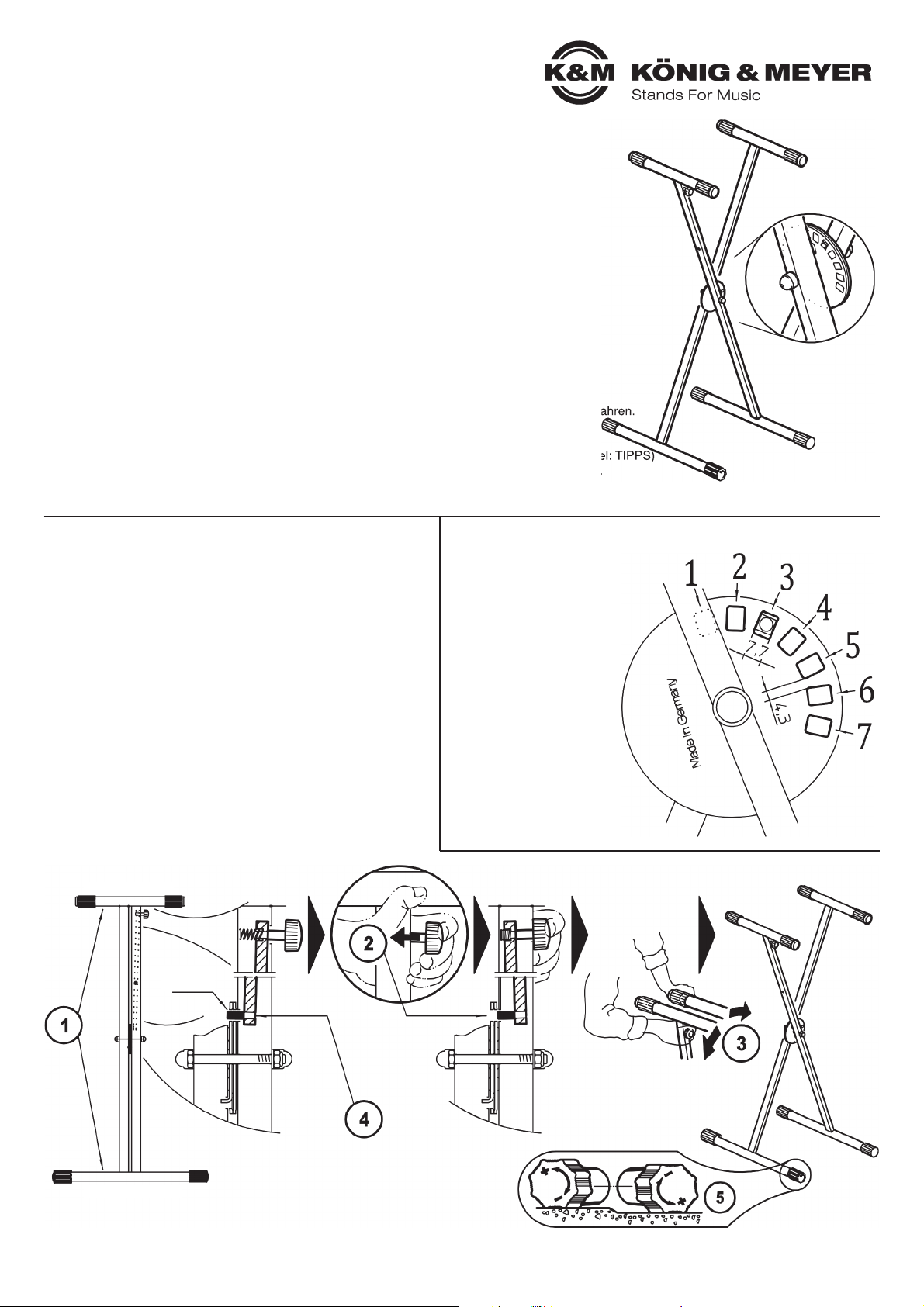
1 Ständer so aufstellen, dass sich die beiden Auflagerohre (350 mm)
1 oben und die Fußrohre (500 mm) unten befinden.
2 Grünen Rändelknopf drücken, so dass der Rastbolzen sich nicht
2 mehr im Eingriff befindet.
3 Auflagerohre auseinanderziehen bis die gewünschte Höhe/Breite
3 in etwa erreicht ist.
3 Nun den Grünen Rändelknopf wieder loslassen und so dem unter
3 Federdruck stehenden Rastbolzen die Möglichkeit geben ins
3 passende Loch der Scheibe einzutauchen. Evtl. müssen dazu
3 die beiden Rohrgestelle noch etwas bewegt werden.
4 BEACHTE: Bitte überzeugen Sie sich davon, dass der Rastbolzen
4 vollständig in die Scheibe eingreift. In diesem Zustand ragt der
4 Bolzen ca. 2 mm aus der Lochscheibe hervor.
5 Bei Bodenunebenheiten den Ausgleichparkettschoner entsprechend
5 verdrehen (+/-).
AUFSTELLANLEITUNG
18940 Keyboardständer
mit patentierter »Smart-Lock« Druckknopfsystem zur Schnellverstellung für:
- unübertroffen schnelles Aufstellen, Verstellen und Zusammenklappen
- bestens geeignet für den mobilen Einsatz: unkompliziert, robust und platzsparend
- die zentrale Stahlscheibe ermöglicht die Einstellung von sieben Positionen für
- stehende oder sitzende Spielweise - oder eben kleinstmöglich zusammengeklappt
- für den Transport
- mit typischen K&M-Qualitätsmerkmalen wie:
- solide Verarbeitung, Leichtgängigkeit, Transportfreundlichkeit, hochwertiger Oberflächen-
- schutz, rutschfeste Gummiauflagen, Ausgleichsparkettschoner für Bodenunebenheiten
- mit der Möglichkeit ein 2. Keyboard aufzunehmen (Aufsatz 18941)
- Höhe/Breite sind universell einstellbar; Fußrohre: ø 30 x 500 mm,
- Auflagerohre: ø 30 x 350 mm, 4,3 kg
Vielen Dank, dass Sie sich für dieses Produkt entschieden haben. Diese Anleitung informiert Sie über alle
wichtigen Schritte bei Aufbau und Handhabung. Wir empfehlen, sie auch für den späteren Gebrauch
aufzubewahren.
KÖNIG & MEYER GmbH & Co. KG
Kiesweg 2, 97877 Wertheim, www.k-m.de
18940-017-55 Rev.03 03-79-277-00 5/17
A. VERSTELLUNGEN
Die Lochscheibe verfügt über
7 Löcher bzw. Einstellvarianten.
Dadurch ist ein breites Spektrum an
unterschiedlichen Höhen (und Breiten)
der Keyboardständerauflagen gegeben. Siehe Kap. AUFSTELLVARIANTEN
HINWEIS
Form und Größe des Rastbolzens sowie der Abstand
der Löcher in der Scheibe
sind bewusst so gewählt, um
dem Keyboardständer eine hohe
Trag- und Widerstandskraft zu
verleihen. Kleiner dimensionierte
Teile hätten eine höhere Bandbreite
an Aufstellvarianten bedeutet - jedoch
zu Lasten der Stabilität.
350 mm = Auflage
500 mm = Fußrohr
ca. 2 mm
Überstand
Rastbolzen
im Eingriff
Rastbolzen nicht
im Eingriff
Page 2
B. AUFSTELLVARIANTEN
PRÜFEN, INSTANDHALTEN, REINIGEN
Bei Wartungsarbeiten auf evtl. Gefährdungen achten (Einklemmen,
Anstoßen). Zur Reinigung am besten ein leicht feuchtes Tuch und ein
nicht scheuerndes Reinigungsmittel benutzen.
FEHLERSUCHE (F) und BESEITIGUNG (B)
F: Stativ wackelt auf dem Boden:
F: B: Ausgleichparkettschoner einstellen, Boden prüfen.
F: Höhe/Breite des Stativs passt nicht:
F: B: Anderes Loch in der Rastscheibe wählen.
F: Keyboard wackelt auf Stativ:
F: B: Unterseite des Keyboards auf Unebenheiten überprüfen.
F: B: Breite des Stativs verändern.
F: Keyboard liegt nicht auf Gummis auf:
F: B: Hintere Gummiringe in passende Position verschieben.
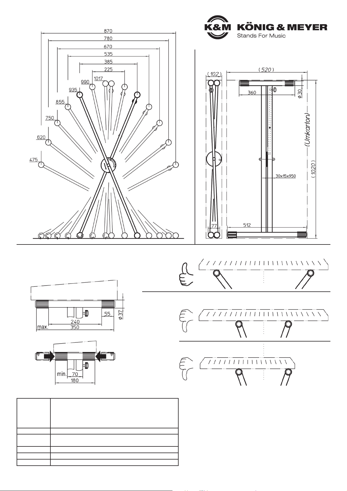
C. ABMESSUNGEN
Transportstellung - (Umkarton)
D. AUFLAGEN ANPASSEN
Die Abstände der Gummiauflagen können dem jeweiligen
Instrument angepasst werden.
Dazu die hinteren Gummiauflagen nach vorne schieben
bis der richtige Abstand erreicht ist.
TECHNISCHE DATEN / SPEZIFIKATIONEN
Material
Rohre und Streben: Stahl, pulverbeschichtet, Farbe schwarz
Schrauben, Muttern, U-Scheiben: Stahl, verzinkt
Rastbolzen: Stahl, vernickelt
Parkettschoner, Gummiauflagen: TPE, Shore 59A schwarz
Griff, Scheibe, Kappen: PA, PE
Traglast max. 40 kg
Abmessungen
Beispiel: Höhe 620 mm x Breite 780 mm
Auflagerohr: ø 30 x 350 mm; Fußrohr: ø 30 x 500 mm
Verpackung Karton: 1025 x 520 x 102 mm
Gewicht 4,3 kg
Zubehör Tasche 18959-000-00, Aufsatz 18941-000-55
Keyboard “groß”
Keyboard “kein”
NICHT OK:
Überstand zu groß
NICHT OK:
Überstand zu knapp
NICHT OK:
Außermittig
OK:
Überstand
angemessen
OK:
Überstand
angemessen
OK:
Zentrisch
NICHT OK:
Überstand zu groß
NICHT OK:
Überstand zu groß
OK:
Zentrisch
OK:
- zentrische
- Platzierung
- angemessene
- Überstände
NICHT OK:
- Überstände
- zu gerine bzw.
- zu groß
- außermittige
- Platzierung
E. TIPPS für sicheren Sitz des Keyboards
Page 3

USAGE NOTES / FUNCTIONS (A-E)
SAFETY NOTES
- Load bearing weight max 40 kg.
- Be sure that the surface will bear the load and is suitable and level.
- The fact that the product is collapsible and adjustable, can result in the risk of pinching/wedging of hands.
- Careful and attentive handling during setup, operation, and disassembly is indispensable.
- Prior to attaching the instrument, be sure that the bolt is properly clicked into place 4.
- Ensure that the weight on the stand is centered, and select the proper setting width (refer to Section: TIPS)
- The end caps are made of high quality material and to the extent possible free of softening agents.
- To protect particularly delicate floors (possibly certain wood floor types) a slip resistant pad should be used, if needed.
1 Setup the stand, such that both top tubes (350 mm) are on top
1 and the feet tubes (500 mm) are on the bottom.
2 Press the green knurled button, to release the locking pin.
3 Pull the support arms apart until the desired height/width has
3 been reached.
3 Now let go of the green knurled button to allow the pneumatic
3 locking pin to slide into the proper drill hole.
3 If required, both tube frames may have to be moved a bit to
3 facilitate this.
4 NOTE: Please ensure that the locking pin
4 is properly in place. The bolt sticks out about
4 2 mm from the hole disk.
5 In the case of uneven surface adjust the balance
5 end caps accordingly (+/-).
SETUP INSTRUCTIONS
18940 Keyboard stand
with patented »Smart-Lock« quick release push-button system for:
- unsurpassed quick setup, adjustment and collapsing
- great for on the road use: uncomplicated, robust and space saving
- the central steel disk provides seven settings ranging from seated to
standing - the transport setting provides the smallest possible footprint
- with typical K&M quality features such as:
- solid workmanship, high quality surface coating, anti-slip rubber tray
- surface protection, rubber slip resistance caps, and balancing end caps for uneven surfaces
- With the option to stack a second keyboard (18941 Stacker)
- Height/width are universally adjustable; Base Tube: ø 30 x 500 mm,
- Top Tubes ø 30 x 350 mm, Weight: 4.3 kg
Thank you for choosing this product. The instructions provide directions to all of the important set up and
handling steps. We recommend you keep these instructions for future reference.
KÖNIG & MEYER GmbH & Co. KG
Kiesweg 2, 97877 Wertheim, www.k-m.de
18940-017-55 Rev.03 03-79-277-00 5/17
A. ADJUSTMENTS
The hole disk is comprised of
7 holes i.e. adjustment options.
This provides a wide range of
different (heights and widths)
to support the keyboard stand.
See Section SETUP OPTIONS
NOTE
Form and size of the locking
pins and the distance between
the holes in the disk were
consciously chosen, to provide
the keyboard stand high weight
bearing capacity and stability.
Holes closer together would have
given the stand a greater range of
setup options but it would have been
at the cost of stability.
350 mm = top tubes
500 mm = feet tubes
ca. 2 mm
projecting
locking pin
engaged
locking pin
not engaged
Page 4

B. SETUP VARIATIONS
CHECK, MAINTENANCE, CLEANING
In the event of workstation maintenance pay attention to possible risks
(the stand is bumped into, pinching/ wedging). To care for the product
use a damp cloth and a non-abrasive cleaning agent.
FAULT FINDING (F) & REMEDY (R)
F: Stand is not stable:
F: B: Adjust balance end caps, check surface.
F: Height/width of the stand does not fit:
F: B: Select a different hole in the disk.
F: Keyboard is not firmly placed on the stand (unstable):
F: B: Check the bottom of the keyboard for uneven surfaces.
F: B: Adjust the width of the stand.
F: The keyboard is not placed on the rubber rests:
F: B: Adjust the back rubber rings to the proper position.
C. DIMENSIONS
Transportation setting (cardboard packaging)
D. ADJUST BASES
The distances between the rubber rests can be adjusted
to the dimensions of the instrument. Just push the rubber
rests to the front until the correct distance has been
selected.
TECHNICAL DATA
Material
Tubes, struts: Steel, powder coated black
Screws, nuts, U-disks: Steel, galvanized
Locking pin: Steel, nickel plated
End caps, rubber rests/top:TPE, shore 59A
Handle, disk, caps: PA, PE
Load max. 40 kg
Dimensions
Example: Height 620 x width 780 mm
Support tubes: ø 30 x 350 mm; Base tubes: ø 30 x 500 mm
Packaging Box: 1020 x 520 x 102 mm
Weight 4.3 kg
Accessories Carrying Case 18959-000-00, Stacker 18941-000-55
Keyboard “large”
Keyboard “small”
NOT OK:
Overlaps too much
NOT OK:
does not overlap
enough
NOT OK:
Not centered
OK:
Overlap
adequate
OK:
Overlap
adequate
OK:
Centered
NOT OK:
Overlaps too much
NOT OK:
Overlaps too much
OK:
Centered
OK:
- centered
- adequate
- overlap
NOT OK:
- does not
- overlap enough
- overlaps too much
- not centered
E. TIPS on how to secure the keyboard
 Loading...