

Page 1

18826 Geräteständer
Vielseitig: für Mischpulte, Monitore, Keyboards, Verstärker
Verstellbar: Höhe: 595 -1015 mm, in 15 Stufen verstellbar
Breite: bis zu 800 mm
Mobil: unkomplizierter Auf- und Abbau, ohne Werkzeuge
Transportfreundliches Packmaß: B x T x H: 105 x 395 x 595 mm
Stabil: Langlebige Stahlkonstruktion; Tragkraft 50 kg
K&M-Qualität: solide Verarbeitung, Leichtgängigkeit, hochwertiger
Oberflächenschutz,
rutschfeste verstellbare Gummiauflagen schützen die Geräte,
Ausgleichsparkettschoner für Bodenunebenheiten
SICHERHEITSHINWEISE
- max. Belastbarkeit 50 kg.
- auf geeigneten , d.h. tragfähigen und ebenen Untergrund achten.
- die beiden Auflagearme müssen auf die gleiche Höhe eingestellt werden.
- die Standfestigkeit hängt u.a. von der Aufstellbreite ab und sollte mind. 250 mm betragen, wobei je nach a. Last (Gewicht,
- Ausdehnung), b. Untergrund (Ebenheit), c. Umgebung (Publikumsverkehr etc.) größere Abstände (max. 800 mm)
- angemessen sein können. Ggf. mit geeigneter Auflageplatte arbeiten.
- sicherstellen, dass die Klemmbolzen (siehe Pos. 10) der Höhenverstellung stets eingerastet sind.
- die Möglichkeit das Produkt zusammenzuklappen und zu verstellen, birgt naturgemäß Einklemmgefahren. Dies betrifft insbesondere
- die Scheren zur Einstellung der Breite. Bitte beachten Sie den Warnhinweis (6).
- Umsichtige und aufmerksame Handhabung bei Aufbau, Betrieb und Abbau sind daher unverzichtbar.
- die Parkettschoner sind aus hochwertigem Material und so weit wie möglich frei von Weichmachern. Zum Schutz von ganz besonders
- empfindlichen Böden (z.B. bestimmte Parkettsorten) sollte ggf. eine rutschfeste Unterlage verwendet werden.
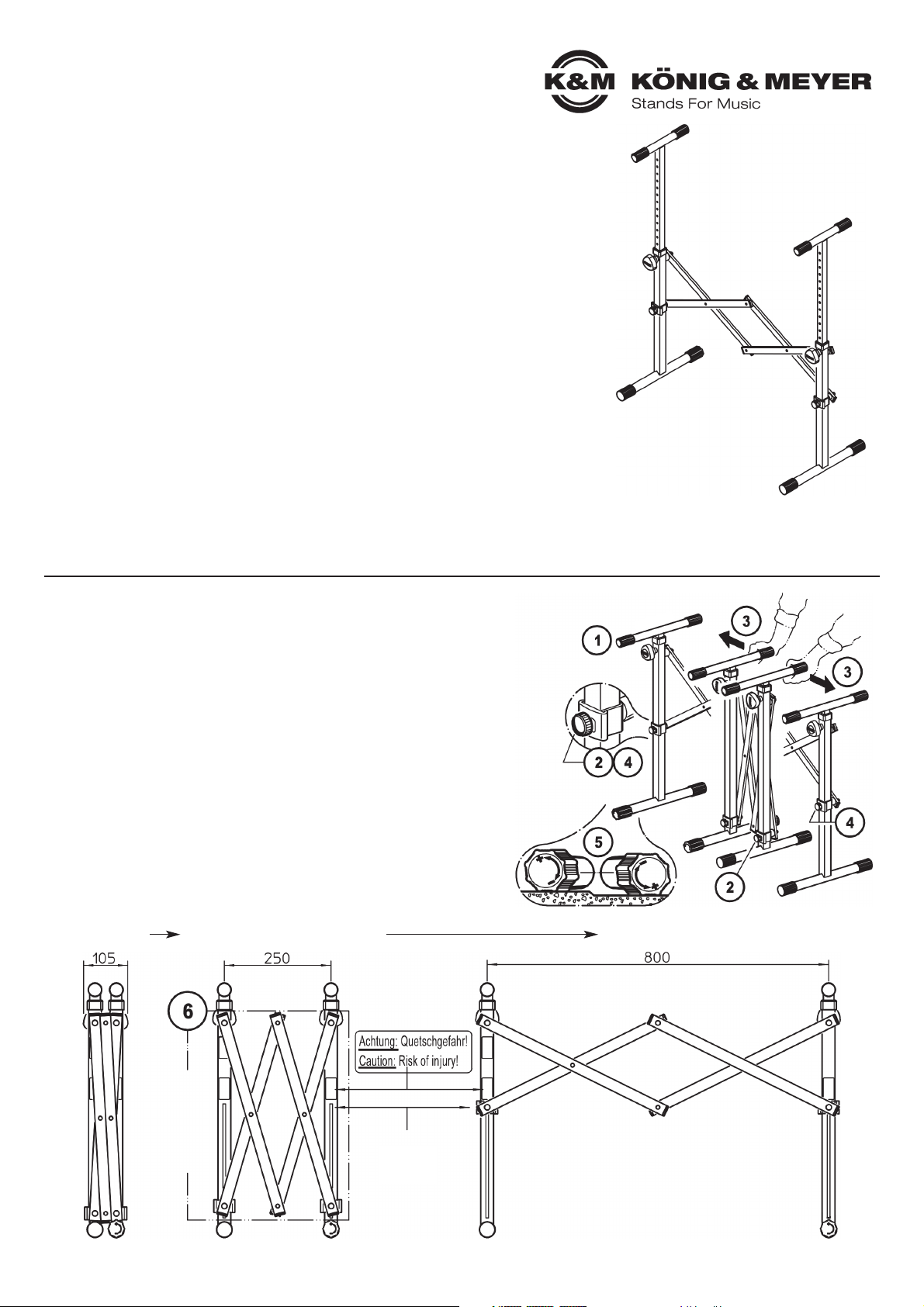
AUFSTELLANLEITUNG
Das Stativ ist bereits komplett vormontiert.
Das Aufstellen ist zudem sehr einfach und erfordert keine Werkzeuge.
1. Ständer so aufstellen, dass sich die Auflagerohre (350 mm) oben
1. und die Fußrohre (395 mm) unten befinden.
2. Rändelschraube (unten) etwas losdrehen
3. Seitenwangen auseinanderziehen bis zur gewünschten Breite (max. 800 mm):
3. HINWEIS: Je größer der Abstand, desto besser für die Standfestigkeit des
3. Ständers. Wir empfehlen, keine Distanzen von unter 250 mm einzu stellen.
3. Ggf. raten wir dazu, eine Auflageplatte zu verwenden (siehe Sicherheitshinweise)
4. Rändelschraube (unten) nun wieder festziehen
5. Bei Bodenunebenheiten den Ausgleichparkettschoner entsprechend
5. verdrehen (+/-).
Das ZUSAMMENKLAPPEN erfolgt in umgekehrter Reihenfolge.
6. WARNUNG: NICHT in den SCHERENBEREICH greifen,
6. da hier Quetschgefahr besteht. Beim Verschieben der Seitenwangen
6. diese deshalb unbedingt immer an den Auflagerohren (3) anfassen.
Vielen Dank, dass Sie sich für dieses Produkt entschieden haben. Diese Anleitung
informiert Sie über alle wichtigen Schritte bei Aufbau und Handhabung. Wir empfehlen,
sie auch für den späteren Gebrauch aufzubewahren.
STATIV AUFSTELLEN
PACKSTÜCK empfohlene MINDESTBREITE
stufenlose Verstellung
MAXIMALE BREITE
Anschlag
BreitenBegrenzung
ACHTUNG!
SCHERENBEREICH
(Erhöhte Vorsicht wg. Quetschgefahr)
350 mm
395 mm
Page 2
BENUTZERHINWEISE / FUNKTIONEN
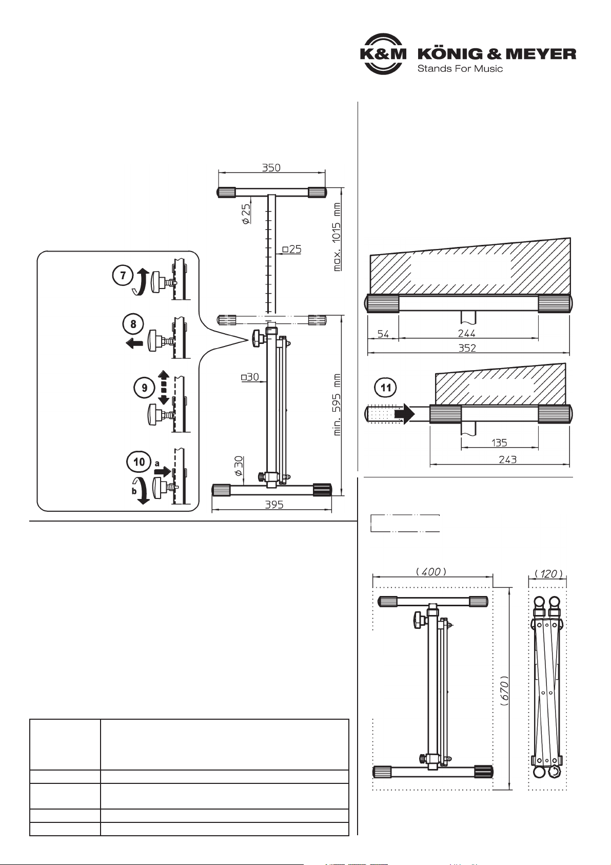
HÖHE EINSTELLEN
Die Auflagerohre sind 15-fach höhenverstellbar:
min. 595 - 625 - 655 - 685 - 715 - 745 - 775 - 805 835 - 865 - 895 - 925 - 955 - 985 - max.1015 mm.
BEACHTE:
Beide Auflagen auf gleiche Höhe einstellen und
Sicherungsbolzen stets eingerastet lassen.
ABMESSUNGEN
PRÜFEN, INSTANDHALTEN, REINIGEN
- bei Wartungsarbeiten auf evtl. Gefährdungen achten (Anstoßen, Einklemmen)
- zur Reinigung am besten ein leicht feuchtes Tuch und ein nicht scheuerndes
- Reinigungsmittel benutzen
FEHLERSUCHE (F) und BESEITIGUNG (B)
F: Stativ wackelt auf dem Boden B: Ausgleichparkettschoner einstellen
B: Boden auf Unebenheiten überprüfen
F: Höhe/Breite des Stativs passt nicht B: Einstellungen ändern (siehe
B: Abmessungen)
F: Gerät wackelt auf Stativ B: Gerätunterseite auf Unebenheiten
B: überprüfen, Einstellungen des
B: Stativs verändern
F: Gerät liegt nicht auf Gummis auf B: Vordere Gummiringe nach hinten
B: verschieben.
N
AUFLAGEN ANPASSEN
Die Abstände der Gummiauflagen können in gewissem Maße dem jeweiligen Gerät angepasst werden.
11. Dazu die vorderen Gummiauflagen nach hinten
11. schieben.
11. BEACHTE:
11. Aus Schutz vor Verlust sitzen die Gummis
11. relativ fest auf den Rohren. Das Verschieben
11. erfordert meist etwas Kraftaufwand.
TRANSPORTSTELLUNG
TECHNISCHE DATEN / SPEZIFIKATIONEN
Material
Stahlrohre - pulverbeschichtet, schwarz
Schrauben, Muttern, Bolzen - verzinkt, vernickelt
Parkettschoner, Gummiauflagen - TPE, Sh.59A schwarz
Griffe, Buchsen - Kunststoff: PA, PE, Fiber
Traglast max. 50 kg
Abmessungen
Breite: max. 800 mm, Höhe: 595-1015 mm
Auflagerohr: ø 25 x 350 mm, Fußrohr: ø 30 x 395 mm
Eigengewicht 5,6 kg
Verpackung Karton: 670 x 400 x 120 mm
KÖNIG & MEYER GmbH & Co. KG
Kiesweg 2, 97877 Wertheim, www.k-m.de
18826-000-55 Rev.02 03-80-317-00 3/18
Umkarton-Maße
Umkarton
7. Klemmschraube
7. etwas lösen
8. Griff ziehen bis der
8. Sicherungsbolzen
8. nicht mehr im
8. Eingriff ist
9. Auszugrohr ein-
8. bzw. ausfahren
10. Sicherungsbolzen
10. in gewünschtes
10. Loch rasten lassen
10. Klemmschraube
10. und wieder fest
10. anziehen
Gerät groß
Gerät klein
Page 3
Thank you for choosing this product. This instruction manual informs you about the
important steps to set up and handle the product. We recommend to keep the
manual in a separate place for a possible later use.
Width
Limitation
Cross Legs /
PACKAGE recommended MINIMUM WIDTH
stepless adjustment
MAXIMUM WIDTH
Width
Limitation
CAUTION!!
SCISSOR AREA
(Increased caution because of crushing)
SAFETY NOTES
- maximum Load 50 kg.
- be sure that the surface will bear the load and is suitable and level.
- both support arms must be adjusted to the same height.
- the stability is dependent upon the setup width and it should be at least 250 mm, however depending on a the load
- (weight, extension), b. uneven surfaces (evenness), c. environment (at a public event etc.)
- Larger distances (max. 800 mm) can be required. If needed, work with the suitable support table.
- ensure that the clamp bolts (see Pos. 10) catch when adjusting the height.
- the fact that the product is collapsible and adjustable, can result in the risk of pinching/wedging. This particularly
- affects the cross legs (scissor legs) used to set the stand width. Please be sure to pay attention to warning (6).
- Careful and attentive handling during setup, operation, and disassembly is indispensable.
- the end caps are made of high quality material and to the extent possible free of softening agents.
To protect particularly delicate floors (possibly certain wood floor types) a slip resistant pad should be used, if needed.
STAND SETUP
SETUP INSTRUCTIONS
The stand is completely pre-assembled.
Setup is very easy and does not require tools.
1. Setup the stand such that the support tube (350 mm) are up top and the
1. feet tubes (395 mm) are on the bottom.
2. Loosen the knurled screws (below) a bit
3. Pull the sides i.e. legs apart to the desired width (max. 800 mm):
3. NOTE: The greater the distance, the better the stability of the stand. We recommend,
3. not to use any distance that is less than 250 mm. If needed, we recommend the
3. use of a suitable support table (please refer to Section: SAFETY NOTES).
4. Re-tighten the knurled screws (below)
5. In the case of uneven surfaces adjust the balancing end caps (+/-).
To collapse the stand, please follow the instructions in reverse order.
6. WARNING: DO NOT place your hands in the cross legs (scissor legs)
6. area to avoid the risk of pinching or wedging your fingers or hands. When
6. pushing the stand legs together, be sure to do so by placing your hands
6. on the support tube (3).
18826 Equipment Stand
Versatile: for sound mixers, monitors, keyboards, amplifiers
Adjustable: height: 595 -1015 mm, adjustable in 15 steps
width: up to 800 mm
Mobile: uncomplicated setup and disassembly, without tools, easy to
transport packaging dimensions: W x D x H: 105 x 395 x 595 mm
Stable: long lived steel construction, load bearing weight 50 kg
K&M-Quality: solid workmanship, smooth handling
anti-slip adjustable rubber top for keyboards
balancing end caps for uneven surfaces
350 mm
395 mm
Page 4

USAGE NOTES / FUNCTION
HEIGHT ADJUSTMENT
The support tubes have 15 height adjustments:
min. 595 - 625 - 655 - 685 - 715 - 745 - 775 - 805 835 - 865 - 895 - 925 - 955 - 985 - max.1015 mm.
ENSURE:
That both support arms are adjusted to the same
height and that the locking bolts are always in
place (the locking bolts catch).
B
DIMENSIONS
CHECK, MAINTENANCE, CLEANING
- In the event of workstation maintenance pay attention to possible risks
- (bumped, pinched, wedged)
- To care for the product use a damp cloth and a non-abrasive cleaning agent
FAULT-FINDING (F) and REPAIR (R)
F: Stand is not stable R: Adjust balance end caps
R: Check surface/floor for uneven surfaces
F: Height/width of the stand does not fit R: Change setting (see
R: dimensions)
F: Equipment is not firmly R: Check bottom of equipment for
F: placed on the stand (unstable) R: uneven surfaces. Adjust the stand
R: settings
F: The keyboard is not placed R: Push the front rubber rings to the
F: on the rubber base R: back
N
ADJUST BASES
The distances between the rubber bases can be
adjusted to the dimensions of the instrument.
11. Just push the rubber bases in the front to the
11. back until the correct distance has been
11. selected.
11. ENSURE:
11. That the rubber base is attached to the tubes
11. tightly, to ensure that they are not lost. Moving
11. the stand requires strength.
TRANSPORTATION SETTINGS
TECHNICAL DATA / SPECIFICATIONS
Material
Steel Tubes - powder coated, black
Screws, nuts, bolts - galvanized, nickel plated
End caps, rubber base/top -TPE, Sh. 59A black
Handles, connectors - plastic; PA, PE, fiber
Load max. 50 kg
Dimensions
width: max. 800 mm, height: 595-1015 mm
support tube: ø 25 x 350 mm, foot tube: ø 30 x 395 mm
Weight 5.6 kg
Packaging Box: 670 x 400 x 120 mm
KÖNIG & MEYER GmbH & Co. KG
Kiesweg 2, 97877 Wertheim, www.k-m.de
18826-000-55 Rev.02 03-80-317-00 3/18
Box Dimensions
Box
7. Turn the clamp
7. screw a bit
8. Pull the handle
8. until the locking
8. bolt is no longer in
8. the drill hole
9. Extend or collapse
9. the extension tubes
10. Place the lock pin/
10. bolt in the desired
10. position (hole) so
10. that it catches and
10. re-tighten the clamp
10. handle
Equipment big
Equipment small
 Loading...