

Page 1
18822 Aufsatz
- für Keyboard-Tische der »Omega«-Serie mit Aufsatz 18811
- Ideal für ein drittes Gerät
- Tragkraft max. 15 kg
- einstellbar in Höhe, Tiefe und Neigung
- Nur geeignet für Aufsatz 18811, NICHT für 18813
- Bitte beachten Sie die Sicherheitshinweise der
- zugrundeliegenden Artikel 18800/18810/18820 und 18811
- Auf feste Verschraubung mit dem Aufsatz achten
- Beide Auflagen 1.d stets auf gleiche Tiefe einstellen
- Auflagegummis 1.n so platzieren, dass das Keyboard
- möglichst sicher und wackelfrei aufliegt
- Verstellung, Wartung, Pflege nur im unbelasteten Zustand
- Zur Reinigung ein leicht feuchtes Tuch und nicht
- scheuerndes Reinigungsmittel benutzen
SICHERHEITSHINWEISE
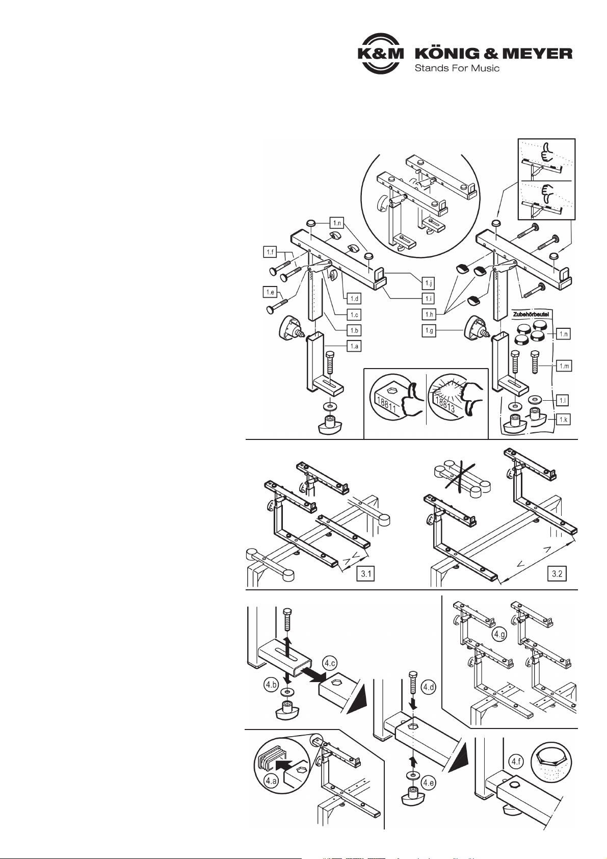
1. BESTANDTEILE
Der Aufsatz 188212 ist bereits vollkommen vormontiert
und besteht aus nachfolgend aufgeführten Einzelteilen:
1.a Halterohr kpl. - 1.b Verstellrohr - 1.c U-Strebe
1.d Auflagerohr - 1.e Schloßschraube M6 x 55 mm mit U-Scheibe
1.f Schloßschraube M6 x 50 mm mit U-Scheibe (2x)
1.g Rast-Klemmschraube - 1.h Klemmmutter klein, M5 (3x)
1.i Rohr-Abdeckkappe (3x) - 1.j Gummianschlag
Zubehörbeutel (1x):
1.k Klemmmutter groß, M6 (2x) - 1.l U-Scheibe ø 6,4 mm (2x)
1.m Sechskantschraube M6 x 28 mm (2x) - 1.n Gummi ø 20 x 5 mm (4x)
AUFBAUANLEITUNG
2. VORBEREITUNG
Zunächst werden die beteiligten Artikel:
- »Omega« Keyboard-Grundtisch,
- 18811 Aufsatz, verstellbar, für »Omega«,
aufgebaut, wie in den jeweils zugehörigen
Aufstellanleitungen beschrieben.
3. AUFSATZ-ABSTÄNDE FESTLEGEN
Anschließend ist zu klären, welchen Abstand
die Auflagen des 18811 haben sollen 3.1/3.2
Befestigen Sie diese dann am »Omega«.
3.1 GERINGER ABSTAND
3.1 z.B. bei Laptop:
3.1 - Auflagerohre des »Omega« verbleiben
3.1 - der breiteren Auflage wegen wohl am Stativ
3.2 WEITER ABSTAND
3.2 z.B. für ein weiteres Keyboard:
3.2 - Auflagerohre des »Omega« können wegen
3.2 - der "Konkurrenz" der Aufsatzrohre entfernt werden
BEACHTE:
Der Abstand der oberen Auflagen entspricht naturgemäß
dem der unteren Auflagen. Sollten die eingesetzten Geräte
unterschiedliche Abstände erforderlich machen, empfehlen
wir Ablageplatten einzusetzen: 18819 unten, 18824 oben.
4. AUFSATZ 18822 MONTIEREN
Die beiden Teile des Aufsatzpaares unterscheiden sich nur
durch die Lage der Klemmmuttern 1.h. Sie können diese
innen- oder außenliegend anbringen (siehe Kap. 5).
4.a Hintere Abschlusskappe der Rohrauflage 18811
4.a entfernen
4.b Verschraubung 1.k.l.m am Stutzen des Halterohres 18821
4.b entfernen
4.c Stutzen nun in die offene Rohrauflage schieben
4.d Sechskantschraube von oben durchstecken und den
4.d Kopf in die sechseckförmige Freimachung eintauchen
4.d lassen
4.e Von unten U-Scheibe aufbringen und Mutter festdrehen
4.f Festigkeit der Verbindung prüfen:
4.f - Sechskantkopf 1.m sitzt verdrehsicher in der
4.f - Freimachung
4.f - Flügelmutter 1.k bis zum Anschlag angezogen
4.f - Rohr 1.a kann nicht mehr von Hand verschoben werden
4.g Zweites Aufsatzrohr in gleicher Weise montieren. Beide
4.g Aufsätze müssen hinsichtlich der Tiefe gleich eingestellt sein.
Vielen Dank, dass Sie sich für dieses Produkt entschieden haben. Diese Anleitung informiert Sie über alle wichtigen Schritte bei Aufbau und Handhabung. Wir empfehlen, sie auch für den späteren Gebrauch aufzubewahren.
1. BESTANDTEILE
3. AUFSATZ-ABSTÄNDE FESTLEGEN
4. AUFSATZ 18822 MONTIEREN
2. VORBEREITUNG
Page 2
BENUTZERHINWEISE / FUNKTIONEN
FEHLERSUCHE (F) und
BESEITIGUNG (B)
F: Aufsatz 18822 lässt sich nicht befestigen
F: B: Falsche Basis, d.h. Aufsatz 18813 muss
F: B: ersetzt werden durch Aufsatz 18811
F: Aufsatz 18822 wackelt.
F: B: Klemmelemente 1.g.h.k festziehen
F: B: Sicherstellen, dass Sechskant in der
F: B: Aussparung sitzt 4.f
F: B. Schraubverbindungen des Aufsatzes
F: B: 18811 sowie des »Omega« auf Festsitz
F: B: prüfen
F: Keyboard sitzt schief oder wackelt
F: B: Für beide Aufsätze (18811, 18822) gilt:
F: B: - vordere Anschläge der Aufsätze
F: B: synchron einstellen 6.3,
F: B: - auf gleiche Höhe der rechten u. linken
F: B: Auflage achten
F: B: - ebenso stets den gleichen Neigungs-
F: B: winkel einstellen
F: B: - Gummiauflagen so platzieren, dass
F: B: Keyboards aufliegen
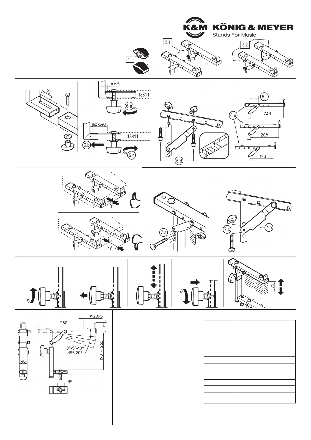
9. ABMESSUNGEN
5. POSITION DER BEDIENELEMENTE (seitliche Klemmmuttern)
Beide Teile des Aufsatzes funktionieren auf die gleiche
Art und Weise. Sie unterscheiden sich jedoch in der
Position der Klemmmutter 1.h, welche bei einem
Aufsatz rechts, beim anderen links montiert sind.
Es gibt also zwei Installationsvarianten,
d.h. sie können wählen zwischen:
5.1 innen liegenden Klemmmuttern
5.2 außenliegenden Klemmmuttern
TECHNISCHE DATEN
Material
Rohre:
Stahl, pulversbeschichtet
Farbe schwarz
Schrauben, Scheiben:
Stahl verzinkt
Kunststoffteile:
PA, PE, TPE, schwarz
Traglast max. 15 kg
Abmessungen
Auflagen:
Breite: 40 mm, Tiefe: 280 mm
Lichte Höhe: 190-265 mm
Gewicht 2,6 kg
Verpackung L x B x H: 300 x 320 x 90 mm
Zubehör
(optional)
18824 Ablage für
Controller Keyboard
KÖNIG & MEYER GmbH & Co. KG
Kiesweg 2, 97877 Wertheim, www.k-m.de
18822-019-55 Rev.03 03-80-374-00 5/19
6. AUFLAGENTIEFE
8. HÖHENEINSTELLUNG
6.1
STUFENLOS
VERSCHIEBEN
Das Halterohr 1.a verfügt
über einen 35 mm langen
Schlitz, zur stufenlosen
Verstellung der Auflage.
6.a Klemmmutter etwas lösen...
6.b ...und Halterohr 1.a in gewünschte Position schieben,
6.c Klemmmutter 1.k wieder festziehen
6.3
SYNCHRONER
ANSCHLAG
Anschlag beider
Auflagerohre sollte
stets gleich, d.h.
parallel zum
Querrohr des
»Omega«
verlaufen.
8.a
Rast-Klemmschraube
1.g etwas losdrehen
8.b
Griff ziehen bis
Sicherungsbolzen
nicht mehr im Eingriff
8.c
Auflagerohr
ein- bzw.
ausfahren
8.d
Sicherungsbolzen einrasten
lassen und Rast-Klemmschraube wieder fest anziehen
8.d Der Aufsatz ist
8.d höhenverstellbar in
8.d 7 Stufen á 12,5 mm
AuflageRohr
von
unten
6.2 TIEFE - VOREINSTELLEN (0-35-70 mm)
6.d Beide Verschraubungen des Auflagerohres komplett demontieren.
6.e Auflage nach Wunsch positionieren (3 Varianten)
6.f BEACHTE: der Abstand der montierten Schrauben
6.f BEACHTE: beträgt stets zwei Bohrungen
7. NEIGUNGSWINKEL (0° - 5° - 10° - 15° - 20°)
7.a Verschraubung auseinandernehmen
7.b U-Strebe wie gewünscht ausrichten (5 Varianten)
7.c U-Strebe und Rohr mittels Schloßschraube abstecken und mit Klemmmutter sichern
Page 3

18822 Stacker
- for »Omega« Table-style keyboard stands with Stacker 18811
- ideal for a third device
- load bearing weight max. 15 kg
- adjustable in height, depth and inclination
- only suitable for Stacker 18811, NOT for 18813
- Please observe the associated safety notes
- For 18800/18810/18820 and 18811
- Ensure that the connection of the stacker is secure
- Both stackers 1.d are to be placed at the same depth
- Ensure that the rubber rests 1.n are placed such
- that the keyboard is securely in place
- In the event of maintenance pay attention to possible risks
- To care for the product, use a damp cloth and a non-
- abrasive cleaning agent
SAFETY NOTES
1. COMPONENTS
Stacker 18821 comes completely pre-assembled
and consists of the following individual parts :
1.a support tube cpl. - 1.b adjustable tube - 1.c washer
1.d support tube - 1.e carriage bolt M6 x 55 mm with washer
1.f carriage bolt M6 x 50 mm with washer (2x)
1.g spring-loaded clamping knob - 1.h locking nut small, M5 (3x)
1.i tube cover cap (3x) - 1.j rubber stop
Accessory bag (1x):
1.k locking nut large, M6 (2x) - 1.l washer ø 6,4 mm (2x)
1.m hexagon bolt M6 x 28 mm (2x) - 1.n rubber ø 20 x 5 mm (4x)
SETUP INSTRUCTIONS
2. PREPARATION
First the two products:
- »Omega« Table-style keyboard stand,
- 18811 Stacker, adjustable, for »Omega«,
are setup, according to the respective
setup instructions.
3. DETERMINE THE STACKER DISTANCES
Then clarify the distance the 18811 Stacker
is to have 3.1/3.2. Attach this onto the »Omega«.
3.1 SMALL DISTANCE
3.1 e.g. for laptop:
3.1 - The stacker tubes of »Omega«
3.1 - the wide stacker stays on the stand
3.2 LARGE DISTANCE
3.2 e.g. for an additional keyboard:
3.2 - The stacker tubes of »Omega« can be
3.2 - removed due to the “competition” between the
3.2 - stacker tubes
NOTE:
The distance of the upper stacker equals the lower stacker.
Should the devices require different distance, we
recommend the use of 18819 on the bottom and 18824
on the top.
4. MOUNT 18822 STACKER
The only difference between the stackers is the position of
the clamping nuts 1.h. They can be applied on the inside or
the outside (see Section 5).
4.a Remove the back tube cap for 18811
4.b Remove the screws 1.k.l.m from support tube
4.c Place the strut in the open tube
4.d Place the hexagon screw from the top
4.d until it is level in the hole
4.e Place the U-disk and nut from below and tighten
4.f Check to ensure that the nut is tight:
4.f - The hexagon head 1.m is level and tight in the
4.f - drill hole
4.f - The locking nut 1.k has been tightened as far
4.f - as it will go
4.f - The support tube 1.a is secure and can no longer be
4.f - moved by hand
4.g Mount the second stacker tube in the same manner.
4.g Both stacker tubes must be adjusted to the same depth.
Thank you for choosing this product. The instructions provide directions to all of the important setup and handling steps. We recommend you keep these
instructions for future reference.
1. COMPONENTS
3. DETERMINE THE STACKER DISTANCES
4. MOUNT 18822 STACKER
2. PREPARATION
Page 4

USAGE NOTES / FUNCTION
FAULT-FINDING (F) and
REPAIR (R)
F: The stacker 18822 cannot be fastened
F: R: Wrong base, i.e. Stacker 18813 must
F: R: be replaced with Stacker 18811
F: The stacker 18822 wobbles
F: R: Tighten the clamping nuts 1.g.h.k
F: R: Ensure that the hexagon is properly
F: B: placed in the opening (hole) 4.f
F: R. Check that the screw connection of the
F: B: »Omega« and stacker 18811 is tight
F: The Keyboard sits inclined or wobbles
F: R: The same applies for both stackers
F: B: (18811, 18822):
F: R: - synchronously adjust the front stops
F: R: of the stackers 6.3,
F: R: - Ensure that the right and left support
F: R: are at the same height
F: R: - also always set the same angle of
F: R: inclination
F: R: - Place rubber pads so that keyboards
F: R: rest on them
9. DIMENSIONS
5. POSITION OF THE OPERATING ELEMENTS (laterally locking nuts)
Both stacker parts function in the same manner.
They do differ in the position of the operating elements 1.h,
which are mounted on the right side of one attachment and
on the left side of the other.
There are two installation options,
i.e. one can select between:
5.1 locking nuts located on the inside
5.2 locking nuts located on the outside
TECHNICAL DATA
Material
Tubes:
Steel, powder coating, black
Screws, washers:
Steel galvanized
Plastic parts:
PA, PE, TPE, black
Load max. 15 kg
Dimensions
Stacker:
Width : 40 mm, Depth: 280 mm
Clear height: 190-265 mm
Weight 2.6 kg
Verpackung L x W x D: 300 x 320 x 90 mm
Accessories
(optional)
18824 Controller keyboard tray
KÖNIG & MEYER GmbH & Co. KG
Kiesweg 2, 97877 Wertheim, www.k-m.de
18822-019-55 Rev.03 03-80-374-00 5/19
6. SUPPORT DEPTH
8. HEIGHT ADJUSTMENT
6.1
STEPLESS
MOVING
The support tube 1.a has
a 35 mm long slot for stepless adjustment of the support.
6.a Loosen the clamping nut a bit...
6.b ... and place the support tube 1.a in the desired position,
6.c Tighten the locking nut 1.k
6.3
SYNCHRONOUS
STOP
The front part of the
stacker tube should
be the same, i.e.
parallel to the cross
tube of the
keyboard stand.
8.a
Loosen the springloaded clamping knob
1.g somewhat
8.b
Pull the handle until
the locking bolt is no
longer in position
8.c
Adjust the
support arm
up or down
8.d
Place the lock bolt in is the
desired hole and let it click
into place then tighten the
spring-loaded clamping
knob
8.d The height of the
8.d support arms can be
8.d adjusted -7 positions-
8.d each step is
12.5 mm.
support
tube
from
below
6.2 DEPTH - PRESET (0-35-70 mm)
6.d Completely dismantle both screw connections of the support tube.
6.e Position the support as desired (3 variants)
6.f NOTE: The distance between the mounted screws
6.f NOTE: is always two holes
7. INCLINATION ANGLE (0° - 5° - 10° - 15° - 20°)
7.a Disassemble the screw connection
7.b Adjust U-strut as required (5 variants)
7.c Lock the U-strut and tube with the carriage bolt and secure with the locking nut
 Loading...