

Page 1
18821 Aufsatz
- für Keyboard-Tisch 18810 »Omega« mit Aufsatz 18811
- Ideal für ein drittes Gerät
- Tragkraft max. 15 kg
- stufenlos verstellbar in der Tiefe (135 mm)
- Höhe: 225 mm, Breite: 40 mm, Auflagentiefe: 280 mm
- Nur geeignet für Aufsatz 18811, NICHT für 18813
- Bitte beachten Sie die Sicherheitshinweise der
- zugrundeliegenden Artikel 18810 und 18811
- Auf feste Verschraubung mit dem Aufsatz achten
- Beide Auflagen 1.8/9 stets auf gleiche Tiefe einstellen
SICHERHEITSHINWEISE
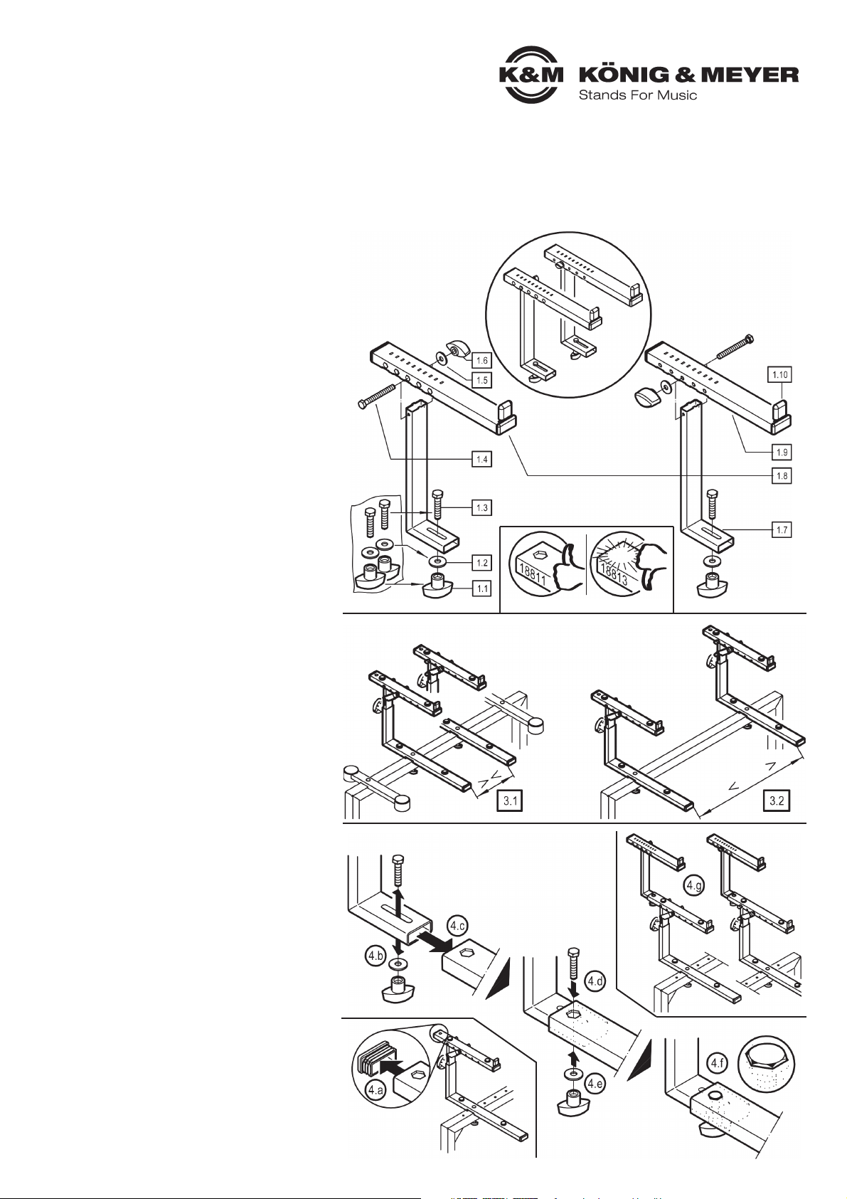
1. BESTANDTEILE
Der Aufsatz 18821 ist bereits vollkommen vormontiert
und besteht aus nachfolgend aufgeführten Einzelteilen:
1.1 Klemmmutter M6 (2x) - im Zubehörbeutel
1.2 U-Scheibe ø 6,4 mm (2x) - im Zubehörbeutel
1.3 Sechskantschraube M6 x 28 mm (2x)- im Zubehörbeutel
1.4 Sechskantschraube M5 x 45 mm (2x)
1.5 U-Scheibe ø 5,3 mm (2x)
1.6 Klemmmutter M5 (2x)
1.7 L-Grundrohr (2x)
1.8 Auflagerohr rechts
1.9 Auflagerohr links
1.10 Gummischoner (2x)
AUFBAUANLEITUNG
2. VORBEREITUNG
Zunächst werden die beteiligten Artikel:
- 18810 »Omega« Keyboard-Grundtisch,
- 18811 Aufsatz, verstellbar, für »Omega«,
aufgebaut, wie in den jeweils zugehörigen
Aufstellanleitungen beschrieben.
3. AUFSATZ-ABSTÄNDE FESTLEGEN
Anschließend ist zu klären, welchen Abstand
die Auflagen des 18811 haben sollen 3.1/3.2
Befestigen Sie diese dann am »Omega« 18810.
3.1 GERINGER ABSTAND
3.1 z.B. bei Laptop:
3.1 - Auflagerohre des 18810 »Omega« verbleiben
3.1 - der breiteren Auflage wegen wohl am Stativ
3.2 WEITER ABSTAND
3.2 z.B. für ein weiteres Keyboard:
3.2 - Auflagerohre des 18810 »Omega« können wegen
3.2 - der "Konkurrenz" der Aufsatzrohre entfernt werden''
BEACHTE:
Der Abstand der oberen Auflagen entspricht naturgemäß
dem der unteren Auflagen. Sollten die eingesetzten Geräte
unterschiedliche Abstände erforderlich machen, empfehlen
wir Ablageplatten einzusetzen: 18819 unten, 18824 oben.
4. AUFSATZ 18821 MONTIEREN
Die beiden Teile des Aufsatzpaares unterscheiden sich nur
durch die Lage der Klemmmuttern. Sie können diese innenoder außenliegend anbringen (siehe Kap.5).
4.a Hintere Abschlusskappe der Rohrauflage 18811
4.a entfernen
4.b Verschraubung am Stutzen des Halterohres 18821
4.b entfernen
4.c Stutzen nun in die offene Rohrauflage schieben
4.d Sechskantschraube von oben durchstecken und den
4.d Kopf in die sechseckförmige Freimachung eintauchen
4.d lassen
4.e Von unten U-Scheibe aufbringen und Mutter festdrehen
4.f Festigkeit der Verbindung prüfen:
4.f - Schraubenkopfes sitzt verdrehsicher in der
4.f - Freimachung
4.f - Flügelmutter bis zum Anschlag angezogen
4.f - Rohr kann nicht mehr von Hand verschoben werden
4.g Zweites Aufsatzrohr in gleicher Weise montieren. Beide
4.g Aufsätze müssen hinsichtlich der Tiefe gleich eingestellt sein.
Vielen Dank, dass Sie sich für dieses Produkt entschieden haben. Diese Anleitung informiert Sie über alle wichtigen Schritte bei Aufbau und Handhabung. Wir empfehlen, sie auch für den späteren Gebrauch aufzubewahren.
1. BESTANDTEILE
3. AUFSATZ-ABSTÄNDE FESTLEGEN
4. AUFSATZ 18821 MONTIEREN
2. VORBEREITUNG
Page 2
BENUTZERHINWEISE / FUNKTIONEN
FEHLERSUCHE (F) und
BESEITIGUNG (B)
F: Aufsatz kann nicht gesichert werden
F: B: Falsche Basis, d.h. Aufsatz 18813
F: B: muss durch 18811 ersetzt werden
F: Aufsatz wackelt
F: B: Klemmmuttern 1.1/1.6 festziehen
F: B: Sicherstellen, dass Sechskante in
F: B: den Aussparungen sitzen 4.f/6.i
F: B. Schraubverbindungen des Grund-
F: B: tisches und des Aufsatzes 18811
F: B: auf Festsitz prüfen
F: Keyboard sitzt schief
F: B: Auszüge 1.8/1.9 auf gleiche Tiefe
F: B: einstellen (siehe Kap.6)
F: B: Für richtige Einstellung des Grund-
F: B: tisches und des Aufsatzes sorgen
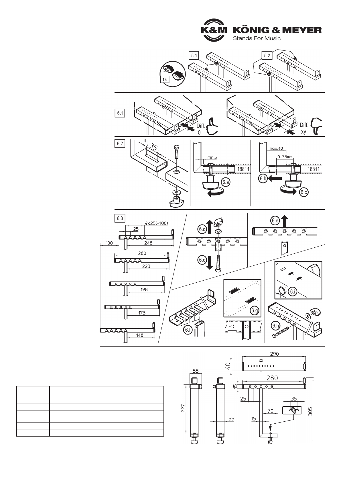
7. ABMESSUNGEN
5. POSITION DER BEDIENELEMENTE
Beide Teile des Aufsatzes funktionieren auf die gleiche Art und Weise.
Sie unterscheiden sich jedoch in der Position der Bedienelemente (1.6, Klemmmutter):
Beim Auflagerohr rechts 1.8 befindet sich die Klemmmutter auf der rechten Seite.
Beim Auflagerohr links 1.9 wird die Klemmmutter analog dazu von links bedient.
Es gibt also zwei Installationsvarianten, d.h. sie können wählen zwischen:
5.1 innen liegenden Bedienelemente
5.2 außenliegenden Klemmmuttern
6. POSITION DER AUFLAGE
6.1 SYNCHRONE EINSTELLUNG
6.1 Der vordere Anschlag beider Auflagerohre
6.1 sollte stets gleich, d.h. parallel zum Quer-
6.1 rohr des Keyboardstativs verlaufen.
6.2 TIEFE - STUFENLOS VERSCHIEBEN
6.2 (0-35 mm)
6.2 Das L-Grundrohr 1.7 verfügt über einen
6.2 35 mm langen Schlitz, der eine stufenlose
6.2 Verstellung der Auflage ermöglicht.
6.a Klemmmutter etwas lösen...
6.b ...und L-Grundrohr in gewünschte
6.b Position schieben,
6.c Klemmmutter wieder festziehen
6.3 TIEFE - VOREINSTELLEN
6.3 (0-25-50-75-100 mm)
6.3 Die Auflagerohre 1.8/1.9 können in fünf ver-
6.3 schiedenen Positionen, m Abstand von jeweils
6.3 25 mm mit dem L-Grundrohr verbunden werden.
6.d Schraubverbindung 1.4-6 demontieren.
6.e Auflagerohr 1.8 vom Grundrohr 1.7 abheben...
6.f ...und in gewünschter Lage wieder platzieren.
6.g Darauf achten, dass die beiden Zapfen des
6.g L-Rohres in die entsprechenden Ausspa-
6.g rungen der Auflage eintauchen.
6.h Sechskantschraube (M5 x 45 mm)seitlich
6.h durchstecken, U-Scheibe aufbringen und
6.h Klemmmutter festziehen.
6.i Darauf achten, dass der Sechskant der
6.i Schraube verdrehsicher in der
6.i Aussparung sitzt
TECHNISCHE DATEN / SPEZIFIKATIONEN
Material
Rohre: Stahl, pulversbeschichtet schwarz
Schrauben, Scheiben: Stahl verzinkt
Kunststoffteile: PA, PE, TPE, schwarz
Traglast max. 15 kg
Abmessungen
Auflage: Breite: 40 mm, Tiefe: 280 mm, Höhe: 227 mm
Abstand: mittig 122 - 732 mm (siehe 18810)
Gewicht 1,7 kg
Verpackung L x B x H: 485 x 260 x 50 mm
KÖNIG & MEYER GmbH & Co. KG
Kiesweg 2, 97877 Wertheim, www.k-m.de
18821-000-55 Rev.04 03-79-261-00 12/17
PRÜFEN, INSTANDHALTEN, REINIGEN
- bei Wartungsarbeiten auf evtl. Gefährdungen achten
- zur Reinigung ein leicht feuchtes Tuch und ein nicht scheuerndes
Reinigungsmittel benutzen
5. BEDIENELEMENTE
6. AUFLAGE
Page 3

18821 Stacker
- for Table-style keyboard stand 18810 »Omega« with Stacker 18811
- Ideal for a third device
- Load bearing weight max. 15 kg
- Variable depth adjustment (135 mm)
- Height: 225 mm, Width: 40 mm, Stacker depth: 280 mm
- Only suitable for Stacker 18811, Not for 18813
- Please observe the associated safety notes
- for 18810 and 18811
- Ensure that the connection of the stacker is secure
- Both stackers 1.8/9 are to be placed at the same depth
SAFETY NOTES
1. COMPONENTS
Stacker 18821 comes completely pre-assembled
and consists of the following individual parts:
1.1 Clamping nut M6 (2x) - in the accessory bag
1.2 U-Disk ø 6,4 mm (2x) - in the accessory bag
1.3 Hexagon screw M6 x 28 mm (2x) - in the accessory bag
1.4 Hexagon screw M5 x 45 mm (2x)
1.5 U-Disk ø 5,3 mm (2x)
1.6 Clamping nut M5 (2x)
1.7 L-Base tube (2x)
1.8 Support tube right
1.9 Support tube left
1.10 Rubber caps (2x)
SETUP INSTRUCTIONS
2. PREPARATION
First the two products:
- 18810 »Omega« Keyboard-Base Table,
- 18811 Stacker, adjustable, for »Omega«,
are setup, according to the respective
setup instructions.
3. DETERMINE THE STACKER DISTANCES
Then clarify the distance the 18811 Stacker
is to have 3.1/3.2. Attach this onto the »Omega« 18810.
3.1 SMALL DISTANCE
3.1 e.g. for laptop:
3.1 - The stacker tubes of 18810 »Omega«
3.1 - the wide stacker stays on the stand
3.2 LARGE DISTANCE
3.2 e.g. for an additional keyboard:
3.2 - The stacker tubes of 18810 »Omega« can be
3.2 - removed due to the “competition” between the
3.2 - stacker tubes
NOTE:
The distance of the upper stacker equals the lower stacker.
Should the devices require different distance, we
recommend the use of 18819 on the bottom and 18824 on
the top.
4. MOUNT 18821 STACKER
The only difference between the stackers is the position of the
clamping nuts. They can be applied on the inside or the outside
(see Section 5).
4.a Remove the back tube cap for 18811
4.b Remove the screws from holding tube strut 18821
4.c Place the strut in the open tube
4.d Place the hexagon screw from the top
4.d until it is level in the hole
4.e Place the U-disk and nut from below and tighten
4.f Check to ensure that the nut is tight:
4.f - The screw head is level and tight in the drill hole
4.f - The wing nut has been tightened as far as it will go
4.f - The tube is secure and can no longer be moved
4.f - by hand
4.g Mount the second stacker tube in the same manner.
4.g Both stacker tubes must be adjusted to the same depth.
Thank you for choosing this product. The instructions provide directions to all of the important setup and handling steps. We recommend you keep these
instructions for future reference.
1. COMPONENTS
3. DETERMINE THE STACKER DISTANCES
4. MOUNT 18821 STACKER
2. PREPARATION
Page 4

USAGE NOTES / FUNCTION
FAULT-FINDING (F) and
REPAIR (R)
F: The stacker cannot be secured
F: B: Wrong base, i.e. Stacker 18813 must
F: B: be replaced with Stacker 18811
F: The stacker is not stable
F: B: Tighten the clamping nuts 1.1/1.6
F: B: Ensure that the hexagon is properly
F: B: placed in the opening (hole) 4.f/6.i
F: B. Check that the screw connection of
F: B: the base table and Stacker 18811
F: B: is tight
F: The keyboard is not balanced
F: B: Ensure that the extensions 1.8/1.9
F: B: have the same depth adjustment (see Section 6)
F: B: Ensure that the base table and
F: B: stacker are adjusted properly
7. DIMENSIONS
5. POSITION OF THE OPERATING ELEMENTS
Both stacker parts function in the same manner.
They do differ in the position of the operating elements (1.6 small nut):
The support tube right 1.8 has the clamp nut on the right side.
The support tube left 1.9 has the clamp nut on the left side.
There are two installation options, i.e. one can select between:
5.1 operating elements located on the inside
5.2 clamp nuts located on the outside
6. POSITION OF THE STACKER
6.1 SYNCHRONOUS ADJUSTMENT
6.1 The front part of the stacker tube should
6.1 be the same, i.e. parallel to the cross tube
6.1 of the keyboard stand.
6.2 DEPTH - VARIABLE ADJUSTMENT
6.2 (0-35 mm)
6.2 The L-base tube 1.7 has a 35mm long slit,
6.2 which provide for the variable adjustment
6.2 of the stacker.
6.a Loosen the clamping nut a bit...
6.b ...and place the L-base tube in the
6.b desired position,
6.c Tighten the clamping nut
6.3 DEPTH - PRESET
6.3 (0-25-50-75-100 mm)
6.3 The support tubes 1.8/1.9 can be placed in
6.3 five different positions, in 25 mm intervals
6.3 connecting to the L-base tube.
6.d Unscrew the screw connection 1.4-6.
6.e Lift the support tube 1.8 from the base tube 1.7...
6.f ...and place it in the desired position.
6.g Ensure that both ends of the L-tube are
6.g placed in the corresponding opening of
6.g the stacker.
6.h Place the hexagon screw (M5 x 45 mm)
6.h from the side, place the U-disk and clamp
6.h nut and tighten.
6.i Ensure that the hexagon of the screw is
6.i placed in the opening (hole) such
6.i that it cannot be turned.
TECHNICAL DATA
Material
Tubes: Steel, powder coating, black
Screws, disks: Steel galvanized
Plastic parts: PA, PE, TPE, black
Load max. 15 kg
Dimensions
Stacker: Width: 40 mm, Depth: 280 mm, Height: 227 mm
Distance: centered 122 - 732 mm (see 18810)
Weight 1.7 kg
Packaging L x W x D: 485 x 260 x 50 mm
KÖNIG & MEYER GmbH & Co. KG
Kiesweg 2, 97877 Wertheim, www.k-m.de
18821-000-55 Rev.04 03-79-261-00 12/17
CHECK, MAINTENANCE, CLEANING
- In the event of maintenance pay attention to possible risks
- To care for the product, use a damp cloth and a non-abrasive
- cleaning agent.
5. OPERATING ELEMENTS
6. STACKER
 Loading...