

Page 1
14100 Kontrabassständer
- standsicher, robust und klein zusammenlegbar, mithin sehr gut geeignet für den mobilen Einsatz
- Haltearme mit instrumentenschonendem Gummiüberzug
- höhenverstellbar; stufenlos von 620 - 1120 mm
- Auf- und Abbau ohne Werkzeuge
SICHERHEITSHINWEISE
- damit das Instrument in der Schale platziert werden kann,
- ist es erforderlich den Stachel auszufahren.
- Erfahrungsgemäß beträgt dieser Abstand 5-8 cm, jedoch ist
- es erforderlich jedes Instrument diesbezüglich zu prüfen.
- Stachel des Instruments mit Bedacht in Auflageschale
- stellen und Korpus zwischen den Haltearmen anlehnen.
- auf geeigneten und ebenen Untergrund achten.
- die Möglichkeit das Produkt zusammenzuklappen oder
- zu verstellen, birgt naturgemäß Einklemmgefahren;
- umsichtige und aufmerksame Handhabung bei Aufbau,
- Betrieb und Abbau sind daher unverzichtbar.
- die Parkettschoner sind aus hochwertigem Material und so
- weit wie möglich frei von Weichmachern; zum Schutz von
- ganz empfindlichen Böden (evtl. bestimmte Parkettsorten)
- sollte ggf. eine rutschfeste Unterlage verwendet werden.
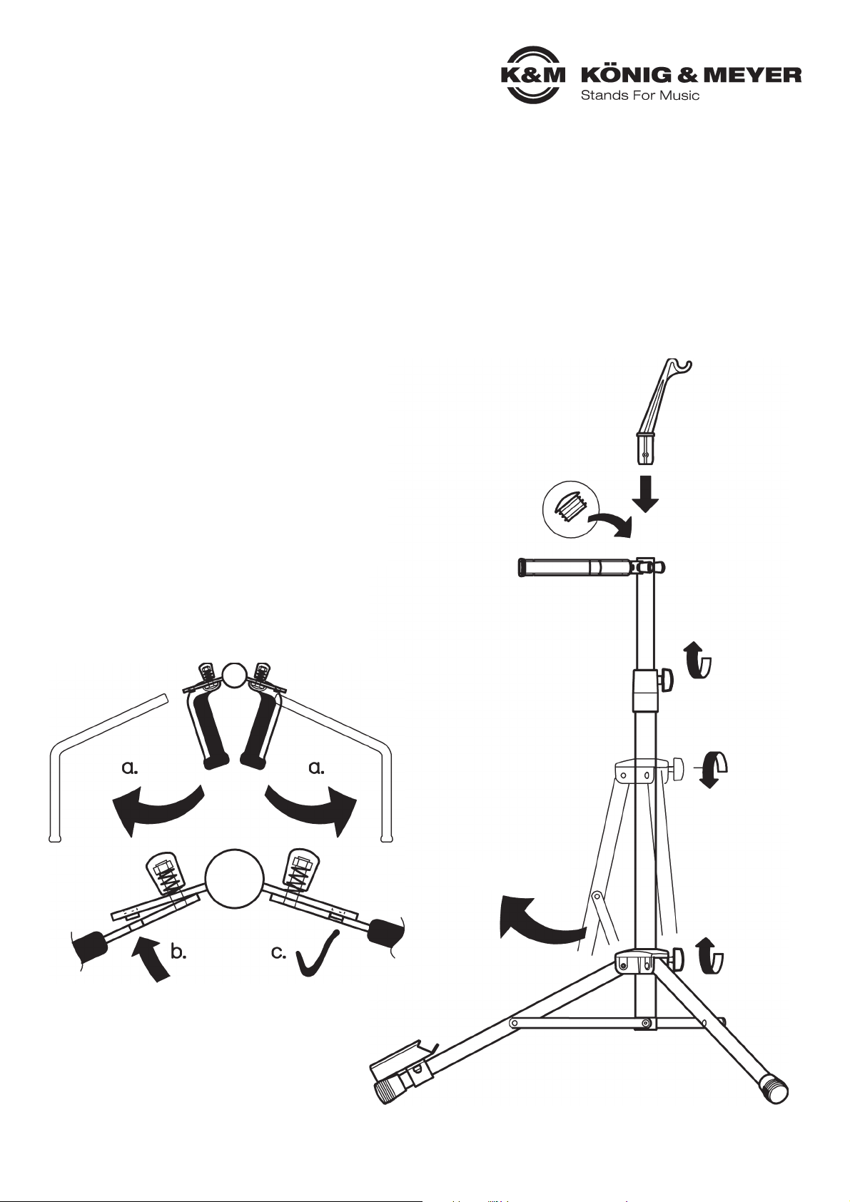
AUFBAUANLEITUNG (1 - 10)
1. Stativ aus Karton entnehmen
Vielen Dank, dass Sie sich für dieses Produkt entschieden haben. Diese Anleitung informiert Sie über alle wichtigen Schritte bei
Aufbau und Handhabung. Wir empfehlen, sie auch für den späteren Gebrauch aufzubewahren.
KÖNIG & MEYER GmbH & Co. KG
Kiesweg 2, 97877 Wertheim, www.k-m.de
14100-011-55 Rev.08 03-80-292-00 10/15
9 a. Haltearme seitlich nach oben klappen
1 b. Noppen ausrichten
1 c. Einrasten lassen
2. Schraube lösen
5. Schraube
5. festdrehen
4. Beste Standsicherheit ist gegeben bei
4. waagerechter Stellung der Verbindungsstreben
6. Höhenverstellung
6. für Auszugrohr
7. Bogenhalter bis zum Anschlag
7. in das Auszugrohr stecken
8. Falls der Bogenhalter nicht
8. erwünscht ist, alternativ
8. die Kappe
8. einstecken
10. Der Zusammenbau
10. findet in umgekehrter
10. Reihenfolge statt.
3. Füsse nach
3. unten klappen
Page 2
BENUTZERHINWEISE / FUNKTIONEN
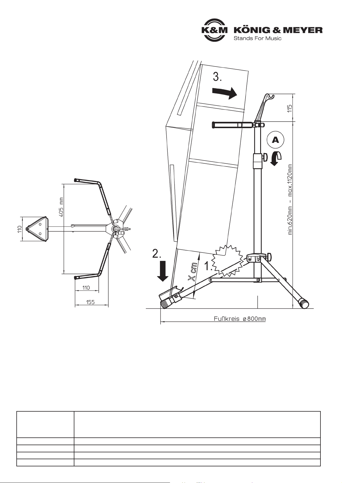
A. HÖHE
A. - Klemmung an der Spannschelle lösen,
A. - Auszugrohr aus- bzw. einfahren, Klemmung
A. - wieder festziehen.
A. - Je nach Stellung der Füße und Position
A. - des Auszugrohres erreicht das Stativ
A. - eine Höhe zwischen 620 und 1120 mm.
B. INSTRUMENT PLATZIEREN
B. 1. Sicherstellen, dass der Stachel
B. 1. ausreichend weit herausragt (X cm). Dies
B. 1. dient der Wahrung des Sicherheitsabstan-
B. 1. des zwischen Instrument und Fußrohr.
B. 2. Zunächst Stachel in Schale stellen und
B. 3. Korpus an den Bügeln anlehnen.
PRÜFEN, INSTANDHALTEN, REINIGEN
- bei Wartungsarbeiten auf evtl. Gefährdungen achten (Einklemmen, Anstoßen)
- zur Reinigung am besten ein leicht feuchtes Tuch und ein nicht scheuerndes Reinigungsmittel benutzen.
FEHLERSUCHE (F) und BESEITIGUNG (B)
F: Stativ wackelt B: Boden prüfen, Fußkreis verstellen, Klemmschrauben anziehen (siehe Fig. 4 und 5)
F: Höhe passt nicht B: Auszugrohr einstellen (siehe Fig. 6)
F: Bügel hält nicht B: Schraube und Feder nachziehen (siehe Fig. 9)
TECHNISCHE DATEN / SPEZIFIKATIONEN
Material
Rohre, Bügel, Streben, Schale: Stahl, pulverbeschichtet schwarz
Schrauben, Nieten: Stahl, verzinkt
Parkettschoner, Schläuche: Thermoplastischer Elastomer (TPE), schwarz
Schellen, Führungen, Griffe: PA
Traglast Kontrabaß
Abmessungen Fußkreisdurchmesser: max. 800 mm, Höhe: 620 mm - 1120 mm
Packmaß, Gewicht 175 x 130 x 605 mm; 2,5 kg
Karton, Gewicht 195 x 140 x 615 mm; 2,9 kg
Page 3

14100 Double bass stand
- stable, robust and collapsible to a small size, also excellently suited for use on the road
- rubber covered support arms that protect instruments
- height adjustable; variable from 620 - 1120 mm
- setup and disassembly without tools
SAFETY NOTES
- Carefully place the end pin into the pin cup and lean the
- body of the instrument on the support arms.
- Be sure that the surface is suitable and level.
- The fact that the product is collapsible and adjustable can
- result in the risk of pinching/wedging of your fingers;
- Careful and attentive handling during setup, operation, and
- disassembly is indispensable.
-The end caps are made of high quality materials and to the
- extent technically possible free of softening agents; for the
- protection of very delicate floors (possibly certain wood
- floor types) a slip resistant pad should be used, if needed.
SETUP INSTRUCTIONS (1 - 10)
1. Take the stand out of the box
Thank you for choosing this product. The instructions provide directions to all of the important set up and handling steps. We
recommend you keep these instructions for future reference.
KÖNIG & MEYER GmbH & Co. KG
Kiesweg 2, 97877 Wertheim, www.k-m.de
14100-011-55 Rev.08 03-80-292-00 10/15
9 a. Flip the support arms up
1 b. Align the knobs
1 c. Allow the knobs to
1 c. click into place
2. Loosen the screw
5. Tighten
5. the screw
4. Best stand stability is provided when the struts
4. are as level as possible
6. Adjust the height
6. of the extension tube
7. Place the bow holder into the
7. extension tube as far as it will go
8. If the bow holder is not
8. needed, place the cap on
8. the tube
10. Disassembly is
10. performed in
10. reverse order.
3. Place the feet
3. in an outward
3. direction
Page 4

USAGE NOTES / FUNCTION
A. HEIGHT
A. - Release the clamp on the clamping bracket,
A. - extend i.e. retract the extension tube,
A. - tighten the clamp.
A. - Depending on the placement of the feet and
A. - position of the extension tube the stand
A. - attains a height of between 620 and 1120 mm.
B. PLACEMENT OF THE INSTRUMENT
B. 1. Ensure that the end pin sticks out enough
B. 1. (X cm). This ensures that the safety distance
B. 1. distance between the instrument and the foot
B. 1. tube is kept.
B. 2. First place the end-pin into the pin cup and
B. 3. Lean the body of the instrument on the
B. 3. support arms.
CHECK, MAINTENANCE, CLEANING
- in the event of workstation maintenance pay attention to possible risks (wedging, workstation being knocked into)
- to care for the product use a damp cloth and a non-abrasive cleaning agent.
FAULT-FINDING (F) and REPAIR (R)
F: Stand is not stable R: Check the floor, adjust the feet/leg position, tighten the clamping screw (see Ill. 4 and 5)
F: Height of the stand is incorrect R: Adjust the extension tube (see Ill. 6)
F: Support arms do not support the instrument R: Tighten screw and spring (see Ill. 9)
TECHNICAL DATA / SPECIFICATIONS
Material
Tube, support arms, struts, cup: Steel, powder coating, black
Screws, rivets: Steel, galvanized
End caps, support arm covering: Thermoplastic elastomer (TPE), black
Brackets, guides, handles: PA
max. load Double bass
Dimensions Base circumference: max. 800 mm, Height: 620 mm - 1120 mm
Pack size, weight 175 x 130 x 605 mm; 2.5 kg
Box, weight 195 x 140 x 615 mm; 2.9 kg
 Loading...