

Page 1
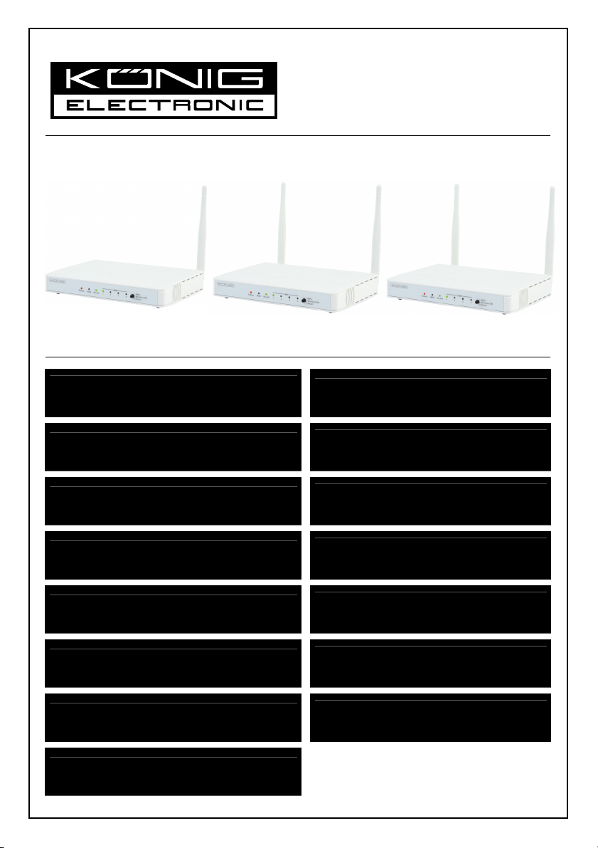
CMP-WNROUT50
CMP-WNROUT55
CMP-WNROUT60
MANUAL (p. 2)
Wireless router
ANLEITUNG (S. 48)
WLAN-Router
MODE D’EMPLOI (p. 96)
Routeur sans fil
GEBRUIKSAANWIJZING (p. 145)
Draadloze router
MANUALE (p. 193)
Router Wireless
MANUAL DE USO (p. 241)
Router inalámbrico
HASZNÁLATI ÚTMUTATÓ (o. 289.)
Vezeték nélküli útválasztó
KÄYTTÖOHJE (s. 336)
Langaton reititin
BRUKSANVISNING (s. 383)
Trådlös router
NÁVOD K POUŽITÍ (s. 431)
Bezdrátový router
MANUAL DE UTILIZARE (p. 479)
Ruter wireless
ΕΓΧΕΙΡΙΔΙΟ XPHΣHΣ (σελ. 526)
Ασύρματο ρούτερ
BRUGERVEJLEDNING (s. 576)
Trådløs router
VEILEDNING (s. 624)
Trådløs ruter
ИНСТРУКЦИЯ (стр. 671)
Беспроводной маршрутизатор
2013-01-29
Page 2
ENGLISH
Wireless router
1) HARDWARE CONFIGURATION
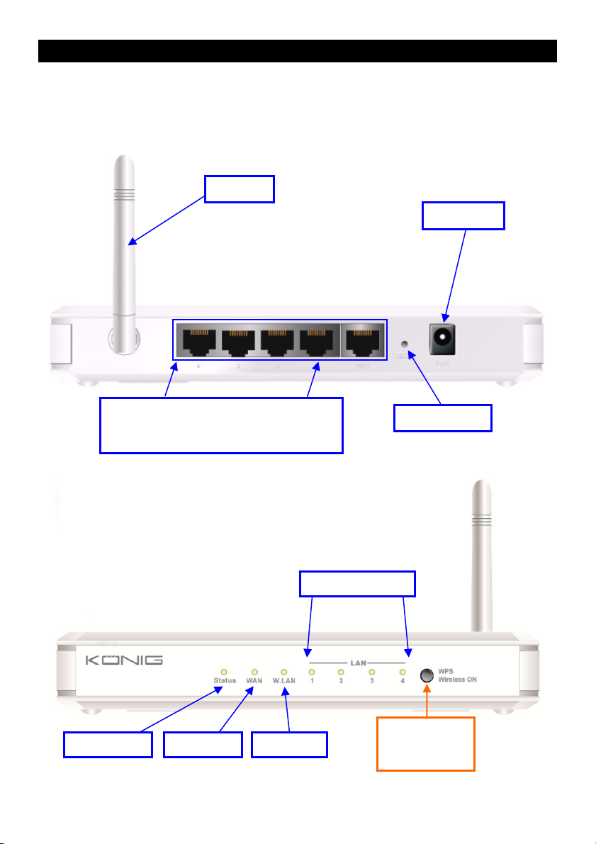
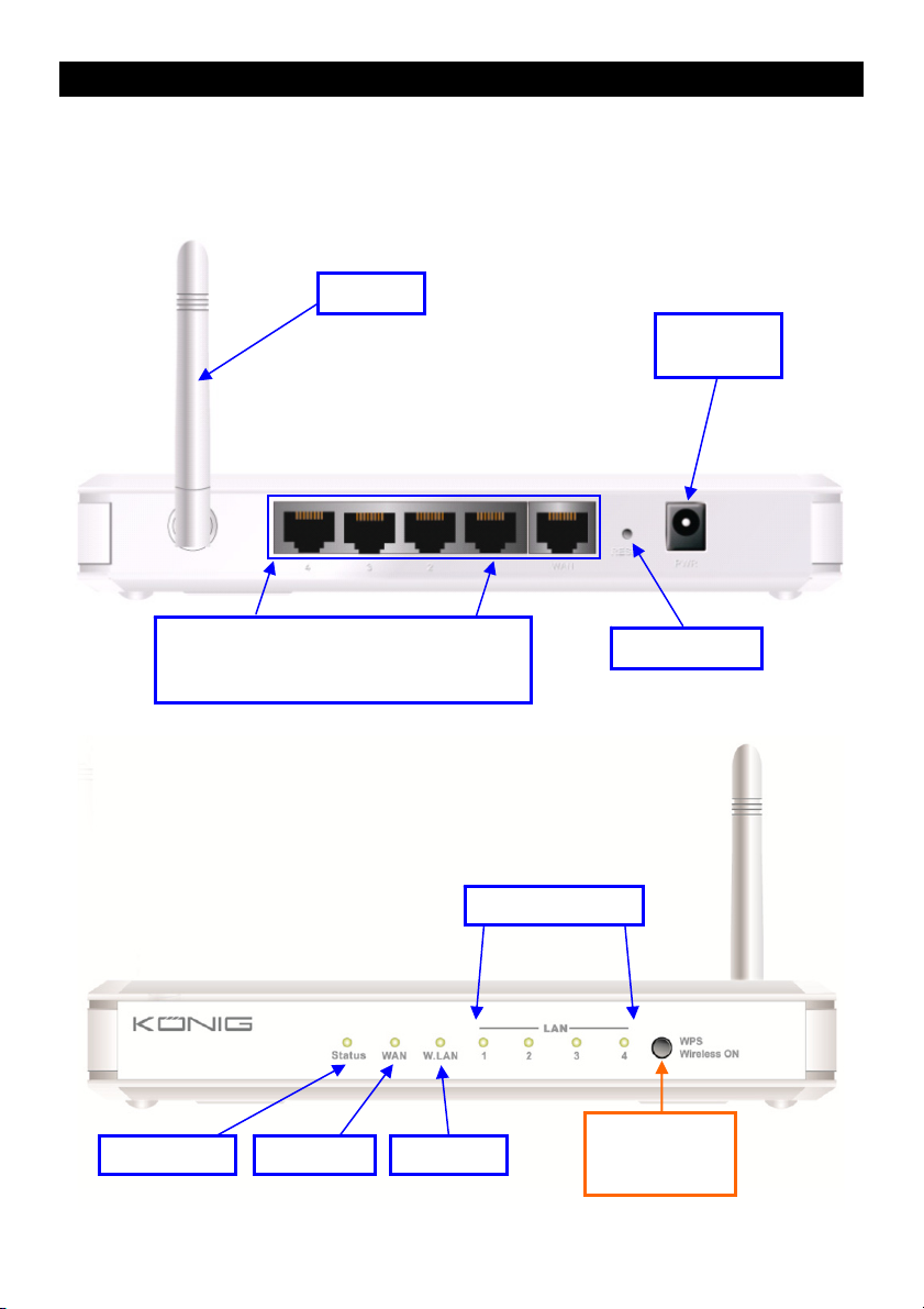
CMP-WNROUT50
Antenna
Power Jack
Auto MDI/MDIX RJ-45 Ports
Automatically senses the types of WAN and
LAN when connecting to the Ethernet
Status LED WAN LED Wi-Fi LED
Reset Button
LAN1~LAN4 LEDs
2 in 1 Button
1. WPS
2. Wireless On
2
Page 3

LED INDICATORS
LED status Description
Status Green flash Device status is working
WAN LED
LAN LED
Wi-Fi LED
Green RJ45 cable is plugged in
Green flash Data access
Green RJ45 cable is plugged in
Green flash Data access
Green Wi-Fi is on
Green flash Data access
Green fast flash Device is in WPS PBC mode
Dark green Wi-Fi is disabled
BUTTON DEFINITION
Description
1. When wireless is switched off, press and hold this button for about 1 second to
WPS
Reset Press and hold for 6 seconds to reset to default settings
enable “wireless radio”.
2. When wireless is switched on, press and hold this button for about 1 second to
execute WPS function.
3
Page 4

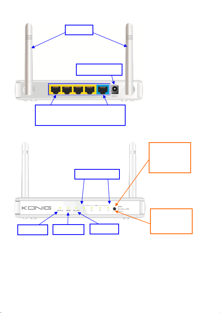
CMP-WNROUT55 and CMP-WNROUT60
Antenna
Power Jack
Status LED
Auto MDI/MDIX RJ-45 Ports
Automatically senses the types of WAN and
LAN when connecting to the Ethernet
LAN1~LAN4 LEDs
WAN LED
Wi-Fi LED
CMP-WNROUT55
3 in 1 Button
1. WPS
2. Wireless ON
3. Reset
CMP-WNROUT60
2 in1 Button
1. WPS
2. Wireless On
4
Page 5

LED INDICATORS
LED status Description
Status Green flash Device status is working
WAN LED
LAN LED
Wi-Fi LED
Green RJ45 cable is plugged in
Green flash Data access
Green RJ45 cable is plugged in
Green flash Data access
Green Wi-Fi is on
Green flash Data access
Green fast flash Device is in WPS PBC mode
Dark green Wi-Fi is disabled
BUTTON DEFINITION
Description
CMP-WNROUT55
When wireless is switched on, press and hold this button (about 1 sec) to execute
WPS function
WPS
Wireless On
(CMP-WNROUT55
only)
Reset
CMP-WNROUT60
1. When wireless is switched off, press and hold this button (about 1 sec) to
enable “Wireless Radio”
2. When wireless is switched on, press and hold this button (about 1 sec) to
execute WPS function
When wireless is switched off, press and hold this button (about 1 sec) to enable
“Wireless Radio”
CMP-WNROUT55
1. Press this button and switch on the device
2. Press and hold for about 3 – 4 seconds. The device will reset to the default
settings. Then the Status LED flashes every second in Normal status
Notice: If the Status LED flashes very fast, it means this button was pressed too
long. Please try again
CMP-WNROUT60
Press and hold this button for 6 seconds to reset to default settings. Release the
button when the device works simultaneously.
5
Page 6

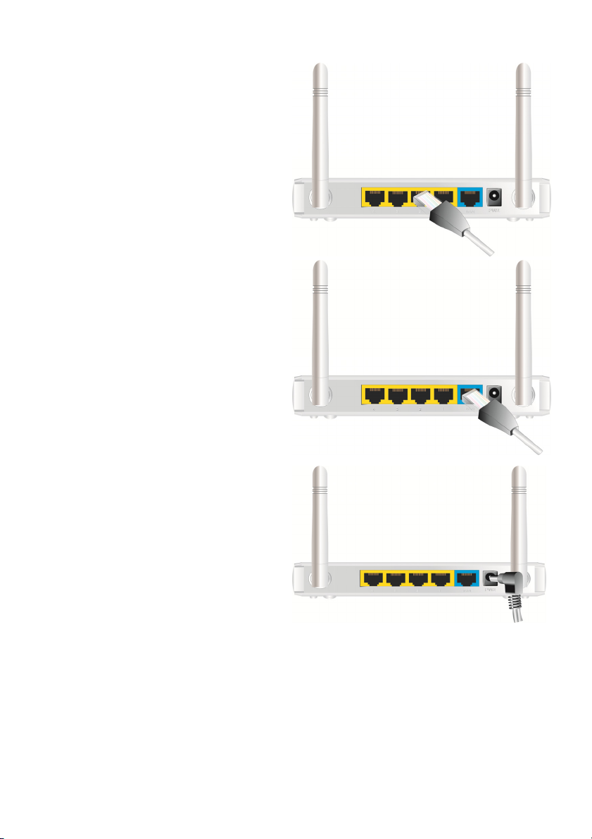
2) HOW TO OPERATE
Step 1. Insert the Ethernet cable into the LAN
Port:
Insert one end of the Ethernet patch cable into
the LAN port on the back panel of the router, and
the other end into an available Ethernet port on
the network adapter of the computer you will use
to configure the unit.
Step 2. Insert the Ethernet patch cable into
the wired WAN port:
Insert the Ethernet patch cable from the DSL
modem into the wired WAN port on the back
panel of the router.
Step 3. Power on the router:
Connect the power adapter to the receptor on the
back panel of your router.
Step 4. Complete the setup.
6
Page 7
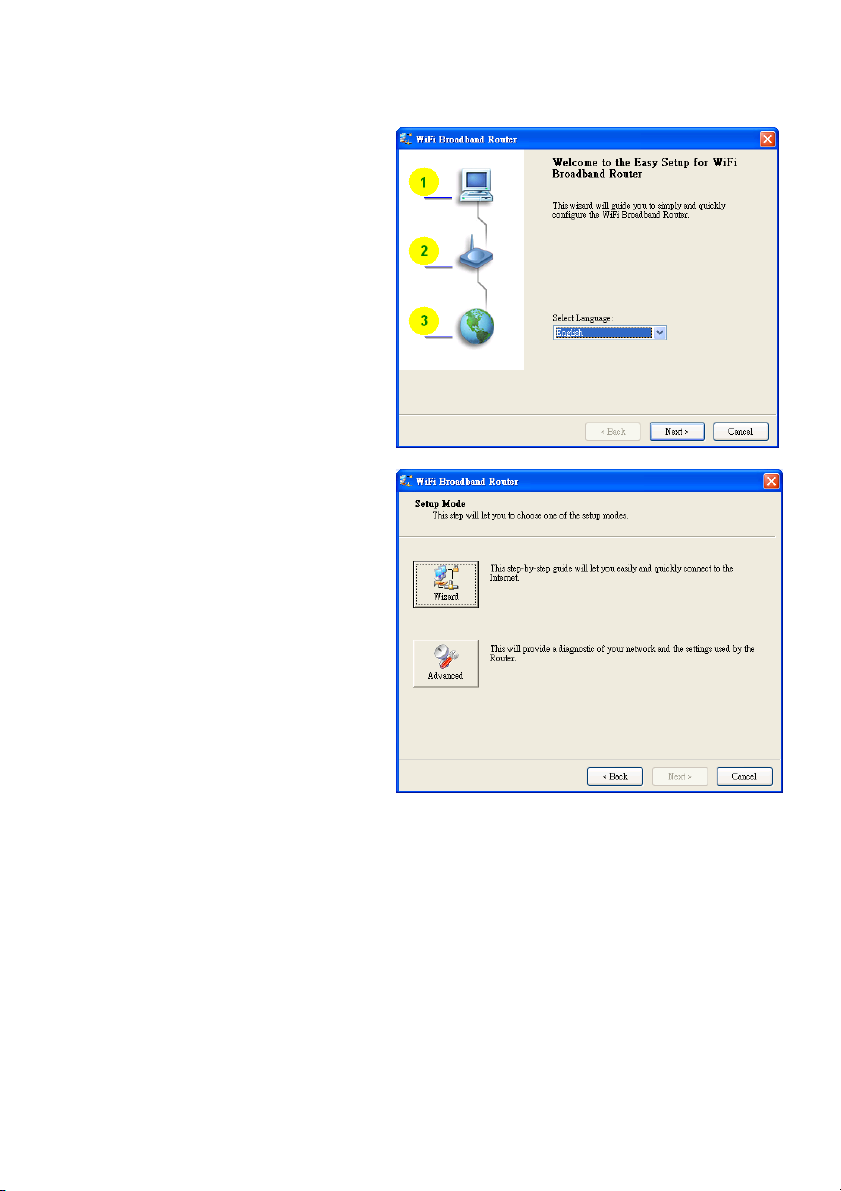
Insert the CD into the CD-ROM reader of your PC. The program, AutoRun, will be executed
automatically. Click the Easy Setup icon for this utility.
Configure the settings by following the steps below:
2.1
Select the correct language and click “Next” to
continue.
2.2 Setup Mode
You can select Wizard mode to run the setup
step by step or run Advanced mode to
diagnose the network settings of the router.
7
Page 8

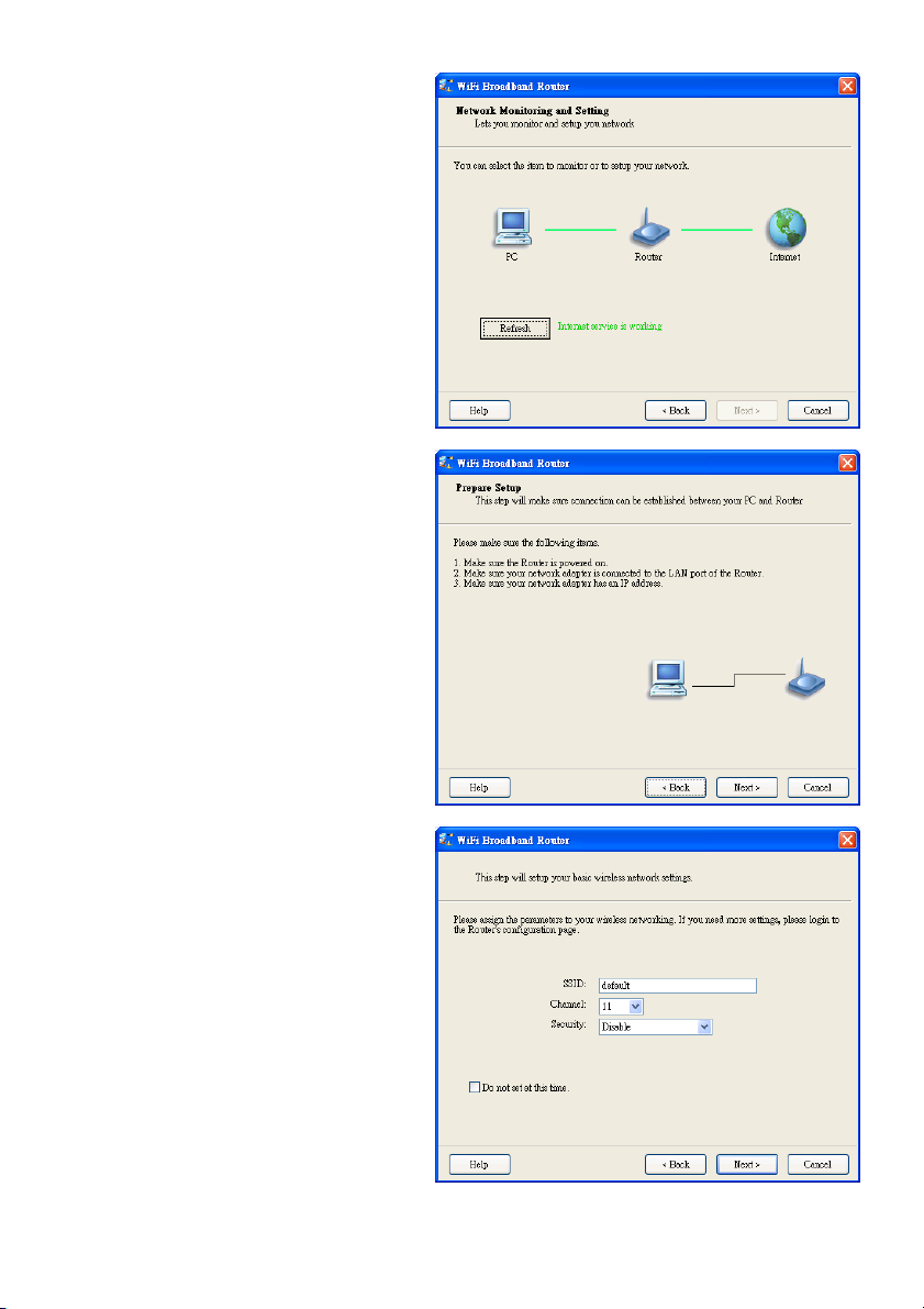
2.3 Advanced Mode Setup.
Check the PC, router or Internet icons for the
status of your PC, router or Internet.
2.4 Quick Wizard Install Mode Setup
1. Check if the router is powered on.
2. Check if your network adapter is connected
to the LAN port of the router.
3. Check if your network adapter has an IP
address.
Click “Next” to continue.
2.5 Wireless Setting
Key in the SSID, Channel and Security
options, and click “Next” to continue.
8
Page 9

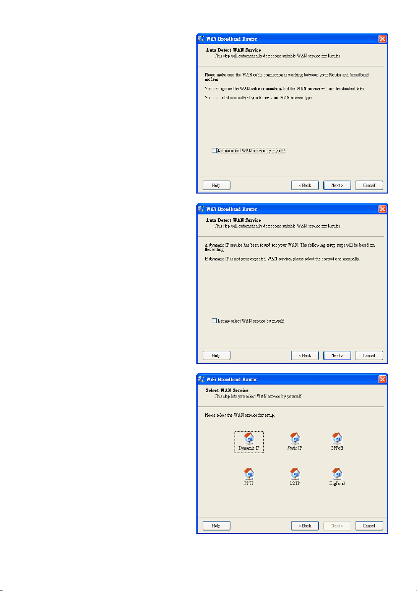
2.6 Auto Detect WAN Service.
Click “Next” to continue.
Disable this function by selecting “Let me
select WAN service by myself”.
Note: This function only supports the
detection of the Dynamic and PPPoE WAN
Services.
For example: the Dynamic WAN type is
detected.
When the detection process is finished, the
router is ready for use.
2.7 Select WAN Service manually.
In manual mode, select an icon and click
“Next” to continue.
9
Page 10
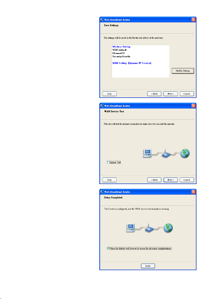
2.8 Apply Settings or Modify.
Click “Next” to apply the settings and continue.
Click “Modify Settings” to change the settings.
2.9 Test the Internet Connection.
Test WAN networking service. Click “Next” to
continue.
You can ignore this step by selecting
“Ignore Test”.
2.10 Setup Completed.
The EzSetup is complete. You can now open
the default web browser to configure the
advanced settings of the router.
Click “Finish” to complete the installation.
10
Page 11

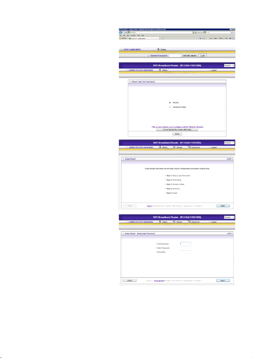
3.) WIZARD CONFIGURATION
Type in the IP Address (http://192.168.0.1)
Insert the and click ‘Login’. The default
password is “admin”.
Select “Wizard” for basic settings, the easiest
way.
Click “Next” to start the wizard.
Step 1:
Set up your system password.
11
Page 12
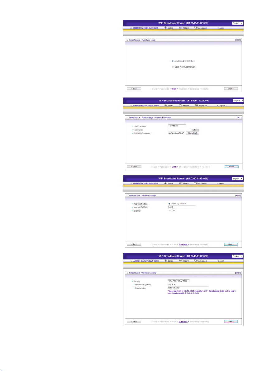
Step 2:
Select “Auto Detecting WAN Type”.
Step 3:
Setup the LAN IP and WAN Type.
Step 4:
Set up your authentication and encryption.
Select WPA-PSK/WPA2-PSK. Now easily fill
in the Preshare key from the bottom of the
router.
12
Page 13
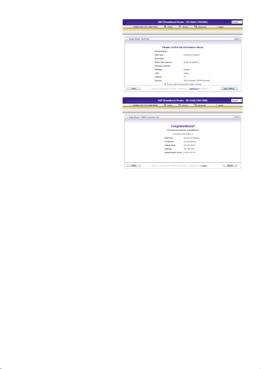
Step 5:
Click “Apply Setting”.
The device will reboot.
Step 6:
Click Finish to complete the wizard. The
Internet connection is established.
13
Page 14
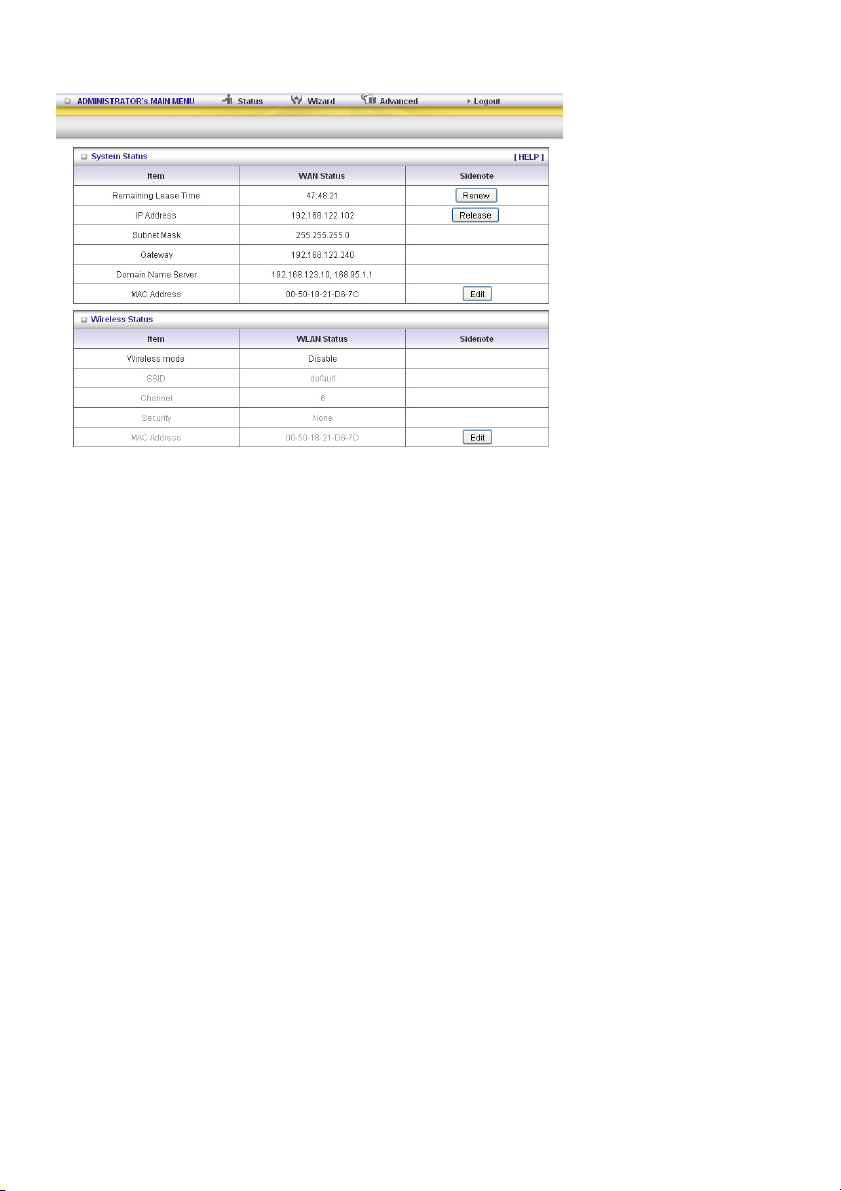
4.) SYSTEM STATUS
This option shows you the product’s working status: WAN status.
If the WAN port is assigned to a dynamic IP, there may appear a “Renew” or “Release” button on the
right side of the column. Click this button to renew or release the IP manually.
Statistics of WAN: enables you to monitor inbound and outbound packets.
14
Page 15
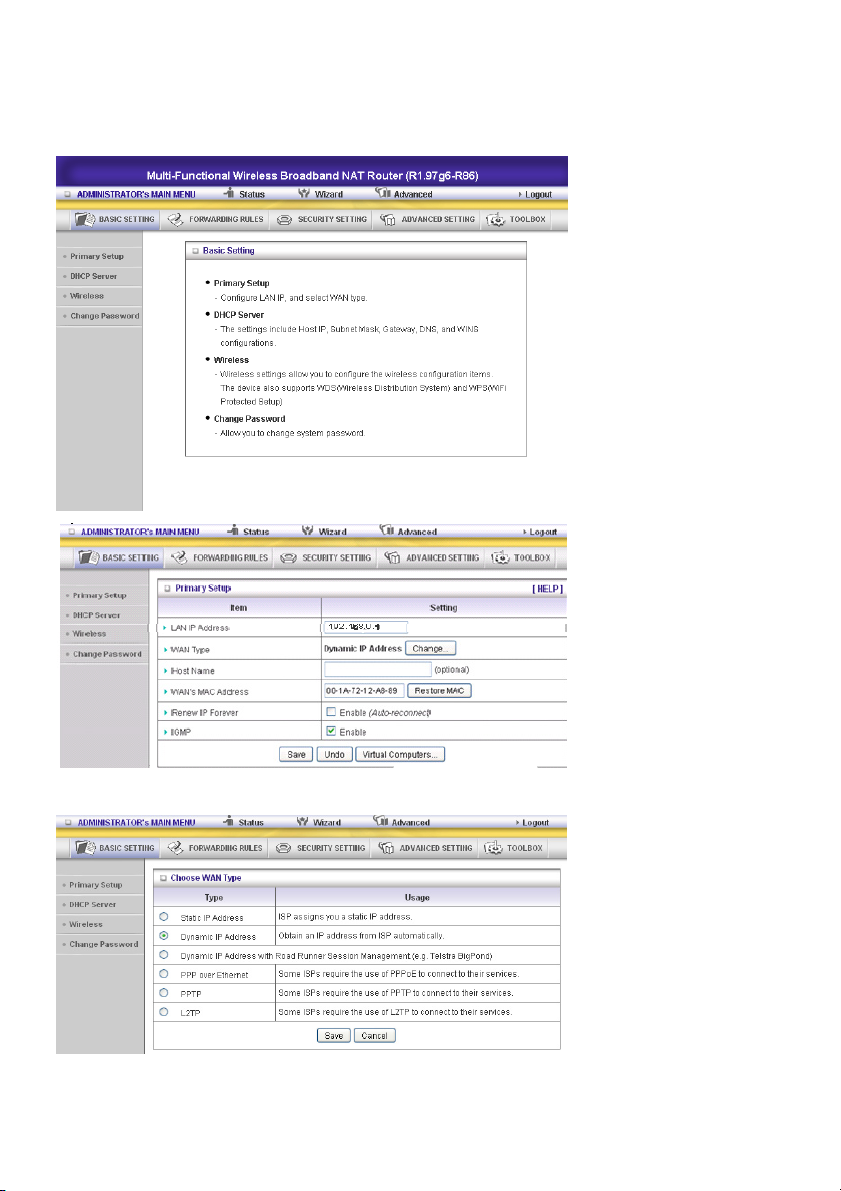
5.) EXTRA SETTINGS
5.1 Basic settings
Please select “Advanced Setting”.
Click “Change”.
This option is primarily to enable this product to work properly. The setting items and the web
appearance depend on the WAN type. Choose correct WAN type before you start.
15
Page 16
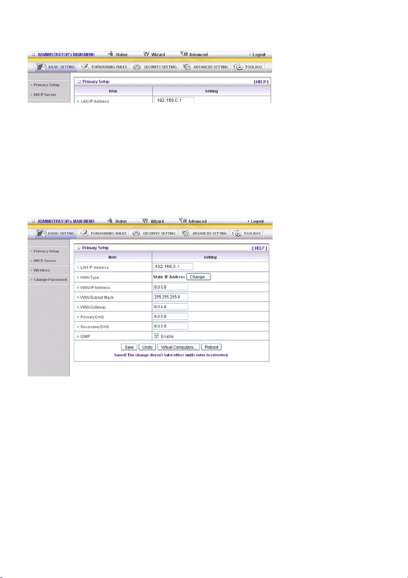
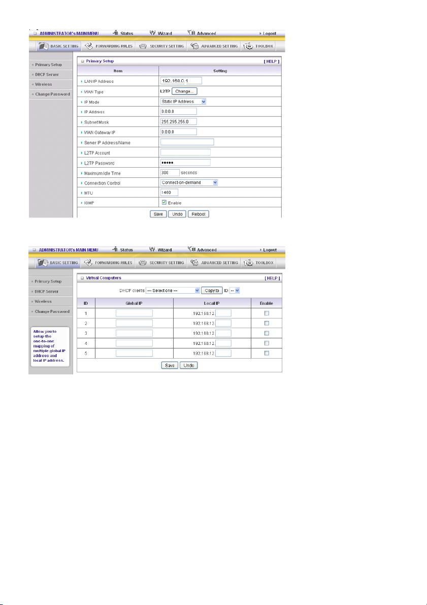
1. LAN IP Address: the local IP address of this device. The computers on your network must use the
LAN IP address of your product as their Default Gateway. You can change it if necessary.
2. WAN Type: WAN connection type of your ISP. Click the Change button to choose a correct one from
the following options:
A. Static IP Address: ISP assigns you a static IP address.
B. Dynamic IP Address: Obtain an IP address from ISP automatically.
C. PPP over Ethernet: Some ISPs require the use of PPPoE to connect to their services.
D. PPTP: Some ISPs require the use of PPTP to connect to their services.
F. L2TP: Some ISPs require the use of L2TP to connect to their services
Static IP Address: ISP assigns you a static IP address:
WAN IP Address, Subnet Mask, Gateway, Primary and Secondary DNS: enter the proper settings
provided by your ISP.
16
Page 17
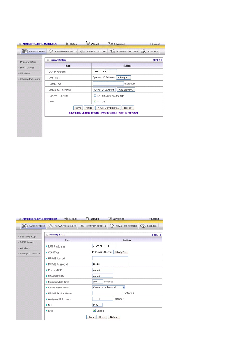
Dynamic IP Address: Obtain an IP address from ISP automatically.
Host Name: optional. Required by some ISPs, for example @Home.
Renew IP Forever: this feature enables this product to renew your IP address automatically when the
lease time is expiring - even when the system is idle.
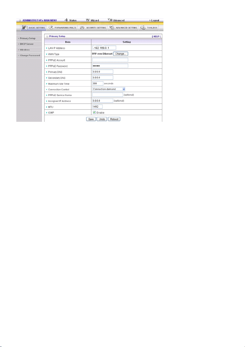
PPP over Ethernet: Some ISPs require the use of PPPoE to connect to their services.
PPPoE Account and Password: the account and password your ISP assigned to you. For security
reasons, this field is left blank. If you do not want to change the password, leave the field empty.
PPPoE Service Name: optional. Input the service name if your ISP requires it. Otherwise, leave it blank.
Maximum Idle Time: the amount of time of inactivity before disconnecting your PPPoE session.
Set it to zero or enable Auto-reconnect to disable this feature.
Maximum Transmission Unit (MTU): Most ISPs offer MTU value to users. The most common MTU
value is 1492.
Connection Control: There are 3 modes to select:
Connect-on-Demand: The device will connect to the ISP when the clients send outgoing packets.
Auto-Reconnect (Always-on): The device will connect to the ISP until the connection is established.
Manually: The device will not make the link until someone clicks the Connect button on the Status page.
17
Page 18
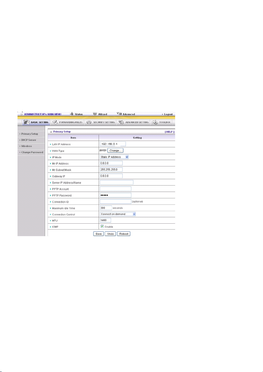
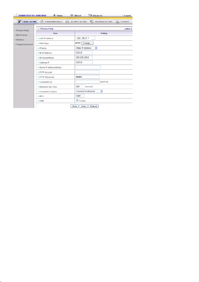
PPTP: Some ISPs require the use of PPTP to connect to their services
First, please check and select the Static IP Address or Dynamic IP Address assigned by your ISP.
1. My IP Address and My Subnet Mask: the private IP address and subnet mask your ISP assigned to
you.
2. Server IP Address: the IP address of the PPTP server.
3. PPTP Account and Password: the account and password your ISP assigned to you. If you do not
want to change the password, keep the field empty.
3. Connection ID: optional. Input the connection ID if your ISP requires it.
4. Maximum Idle Time: the time of no activity to disconnect your PPTP session. Set it to zero or enable
Auto-reconnect to disable this feature. If Auto-Reconnect is enabled and the system has restarted or
the connection has been disconnected, the router will connect to the ISP automatically.
Connection Control: There are 3 modes to select:
Connect-on-demand: The device will connect to the ISP when the clients send outgoing packets.
Auto-Reconnect (Always-on): The device will connect to the ISP until the connection is established.
Manually: The device will not make the link until someone clicks “Connect” on the Status page.
L2TP: Some ISPs require the use of L2TP to connect to their services
First, please check your ISP assigned and select Static IP Address or Dynamic IP Address.
For example: Use Static
1. My IP Address and My Subnet Mask: the private IP address and subnet mask your ISP assigned to
you.
2. Server IP Address: the IP address of the PPTP server.
3. PPTP Account and Password: the account and password your ISP assigned to you. If you do not
want to change the password, leave this field blank.
4. Connection ID: optional. Input the connection ID if your ISP requires it.
5. Maximum Idle Time: the time of no activity to disconnect your PPTP session. Set it to zero or enable
Auto-reconnect to disable this feature. If Auto-Reconnect is enabled and the system has restarted or
the connection has been disconnected, the router will connect to the ISP automatically.
Connection Control: There are 3 modes to select:
Connect-on-demand: The device will link up with ISP when the clients send outgoing packets.
Auto-Reconnect (Always-on): The device will connect to the ISP until the connection is established.
Manually: The device will not connect until someone clicks “Connect” on the Status page.
18
Page 19

Virtual Computers (only for Static and Dynamic IP address WAN type)
Virtual Computer enables you to use the original NAT feature, and allows you to setup the one-to-one
mapping of multiple global IP address and local IP address.
• Global IP: Enter the global IP address assigned by your ISP.
• Local IP: Enter the local IP address of your LAN PC corresponding to the global IP address.
• Enable: Check this item to enable the Virtual Computer feature.
19
Page 20
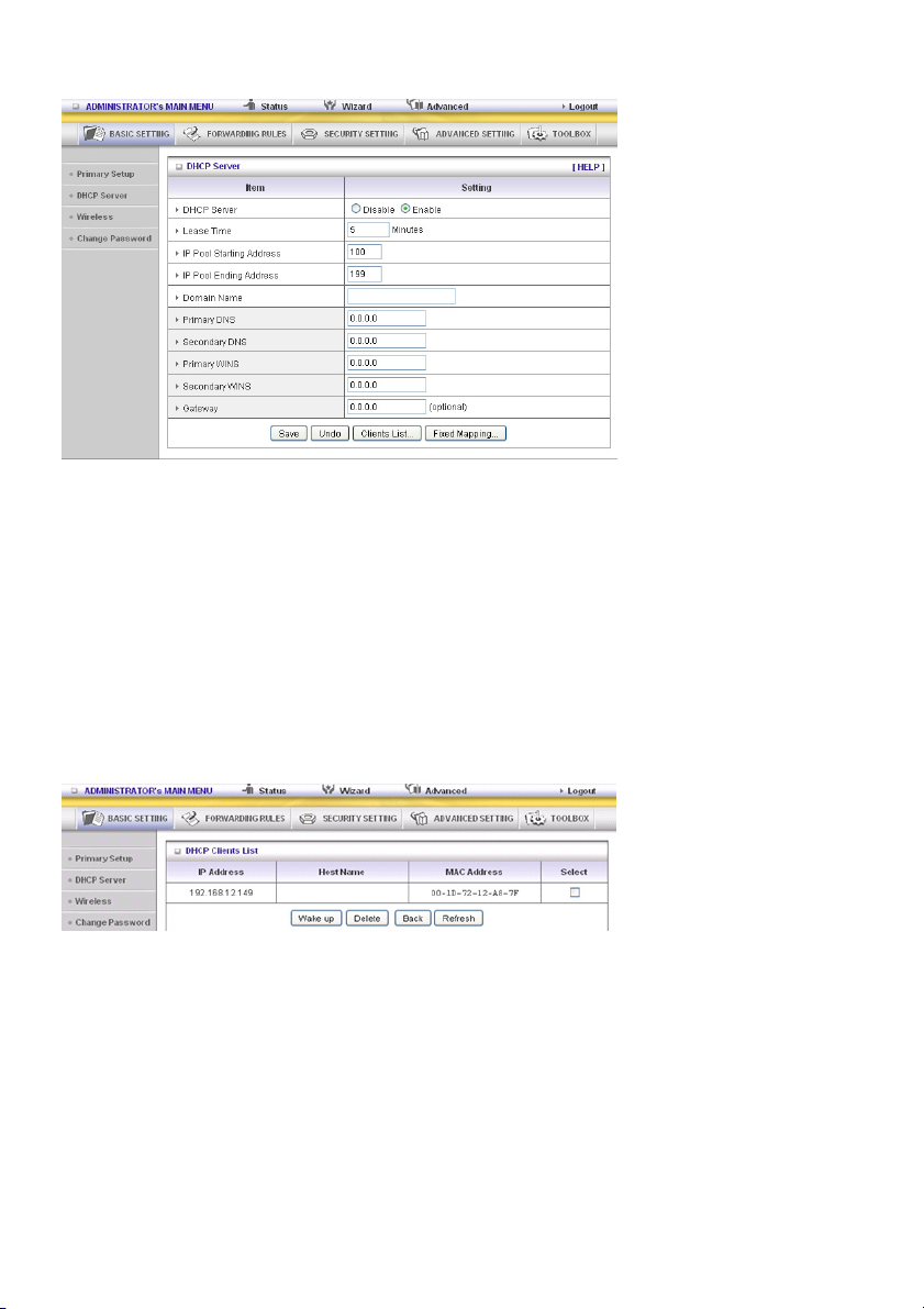
DHCP Server
Press “More>>”
1. DHCP Server: Choose “Disable” or “Enable”.
2. Lease Time: This is the length of time that the client may use the IP address assigned by the DHCP
server.
3. IP Pool Starting Address/IP Pool Starting Address: Whenever there is a request, the DHCP
server will automatically allocate an unused IP address from the IP address pool to the requesting
computer. You must specify the starting and ending address of the IP address pool.
4. Domain Name: Optional, this information will be passed to the client.
5. Primary DNS/Secondary DNS: This feature allows you to assign DNS Servers
6. Primary WINS/Secondary WINS: This feature allows you to assign WINS Servers
7. Gateway: The Gateway Address would be the IP address of an alternate Gateway.
This function enables you to assign another gateway to your PC when the DHCP server offers an IP
to your PC.
8. DHCP Client List:
20
Page 21
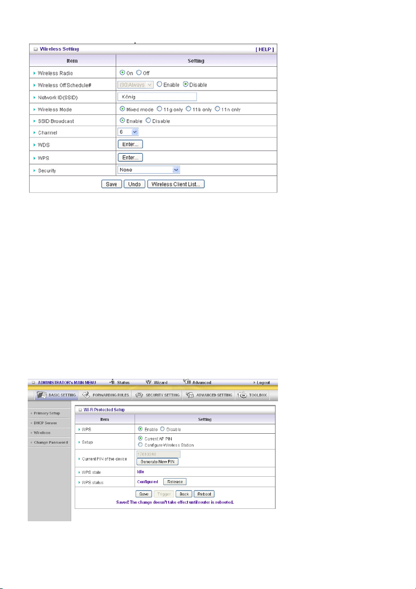
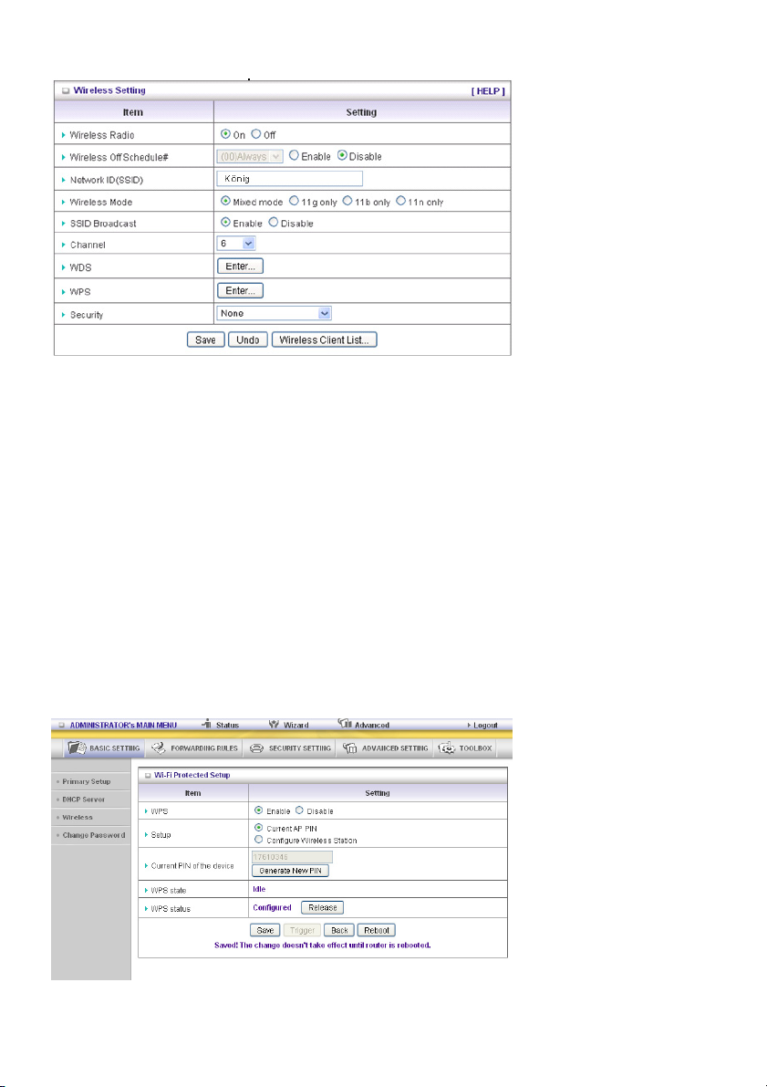
Wireless Setting
Wireless Setting allows you to set the wireless configuration items.
Wireless Radio: The user can turn Wireless Service on or off.
Wireless Off Schedule#: Before switching Wireless Radio off, the device will detect if a wireless
station is online. Then it will, depending on, Schedule “01:00~08:30”, disable the Wi-Fi service.
Network ID (SSID): Network ID is used for identifying the Wireless LAN (Wi-Fi). Client stations can
roam freely over this product and other access points that have the same Network ID. (The factory
setting is “König”)
SSID Broadcast: The router will broadcast beacons that have some information, including SSID so
that the wireless clients know how many AP devices there are by scanning this function in the network.
Therefore, if this function is disabled, the wireless clients cannot find the device from the beacons.
Channel: The radio channel number. The permissible channels depend on the Regulatory Domain.
WPS (Wi-Fi Protection Setup)
WPS is Wi-Fi Protection Setup, which is similar to WCN-NET and offers a safe and easy access in a
wireless connection.
21
Page 22
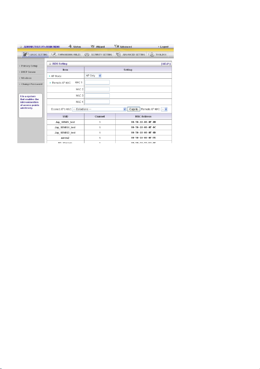
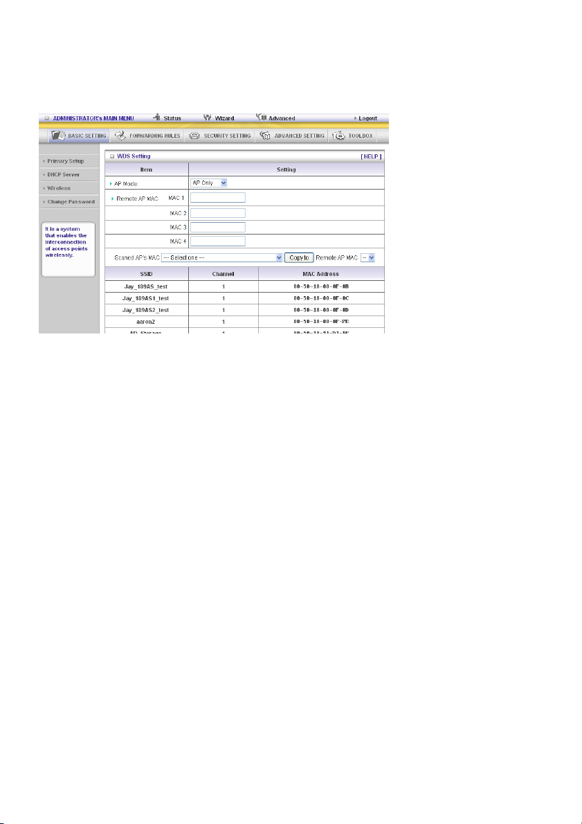
WDS (Wireless Distribution System)
WDS operation as defined by the IEEE802.11 standard has been made available. By using WDS it is
possible to wirelessly connect access points, and in doing so extending a wired infrastructure to
locations where cabling is not possible or inefficient to implement.
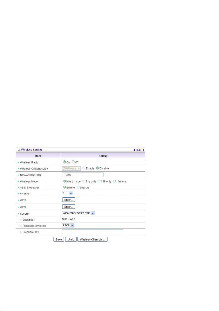
Security: Select the data privacy algorithm you want. Enabling the security can protect your data while
it is being transferred from one station to another.
There are several security types to use:
WEP:
When you enable the 128 or 64 bit WEP key security, please select one WEP key and insert 26 or 10
hexadecimal (0, 1, 2…8, 9, A, B…F) digits.
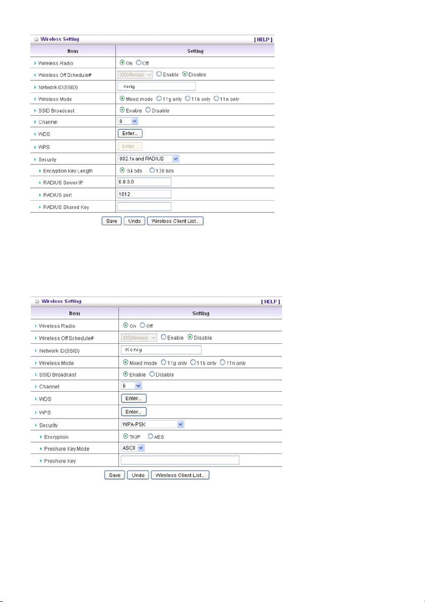
802.1X
The check box is used to change the function of the 802.1X. When the 802.1X function is enabled, the
wireless user must authenticate to this router first to use the network service.
RADIUS Server
IP address or the 802.1X server’s domain name.
RADIUS Shared Key
Key value is shared by the RADIUS server and this router. This key value is consistent with the key
value in the RADIUS server.
22
Page 23

A-PSK
1. Select Encryption and Preshare Key Mode
If you select HEX, you have to fill in 64 hexadecimal (0, 1, 2…8, 9, A, B…F) digits. If ASCII is
selected, the length of the preshared key is between 8 and 63 digits.
2. Fill in the key, e.g. 12345678
WPA
The check box is used to change the function of the WPA. When the WPA function is enabled, the
wireless user must authenticate to this router first to use the network service. RADIUS Server IP
address or the 802.1X server’s domain name.
Select Encryption and RADIUS Shared Key
If you select HEX, you have to fill in 64 hexadecimal (0, 1, 2…8, 9, A, B…F) digits.
If ASCII is selected, the length of the preshared key is between 8 and 63.
23
Page 24
Key value is shared by the RADIUS server and this router. This key value is consistent with the key
value in the RADIUS server.
WPA2-PSK (AES)
1. Select Preshared Key Mode
If you select HEX, you have to fill in 64 hexadecimal (0, 1, 2…8, 9, A, B…F) digits.
If ASCII is selected, the length of the preshared key is between 8 and 63 digits.
2. Fill in the key, e.g. 12345678
WPA2 (AES)
The check box is used to change the function of the WPA. When the WPA function is enabled, the
wireless user must authenticate to this router first to use the network service. RADIUS Server IP
address or the 802.1X server’s domain name.
Select RADIUS Shared Key
If you select HEX, you have to fill in 64 hexadecimal (0, 1, 2…8, 9, A, B…F) digits.
If ASCII is selected, the length of the preshared key is between 8 and 63 digits.
The key value is shared by the RADIUS server and this router. This key value is consistent with the key
value in the RADIUS server.
WPA-PSK /WPA2-PSK
The router will detect automatically which Security type the client uses to encrypt.
1. Select Preshared Key Mode
If you select HEX, you have to fill in 64 hexadecimal (0, 1, 2…8, 9, A, B…F) digits
If ASCII is selected, the length of the preshared key is between 8 and 63.
2. Fill in the key, e.g. 12345678
WPA/WPA2
The check box is used to switch the function of the WPA. When the WPA function is enabled, the
wireless user must authenticate to this router first to use the network service. RADIUS Server The
router will detect automatically which Security type (WPA-PSK version 1 or 2) the client uses to encrypt.
IP address or the 802.1X server’s domain name.
Select RADIUS Shared Key
If you select HEX, you have to fill in 64 hexadecimal (0, 1, 2…8, 9, A, B…F) digits.
If ASCII is selected, the length of preshare key is from 8 to 63.
Key value shared by the RADIUS server and this router. This key value is consistent with the key value
in the RADIUS server.
24
Page 25
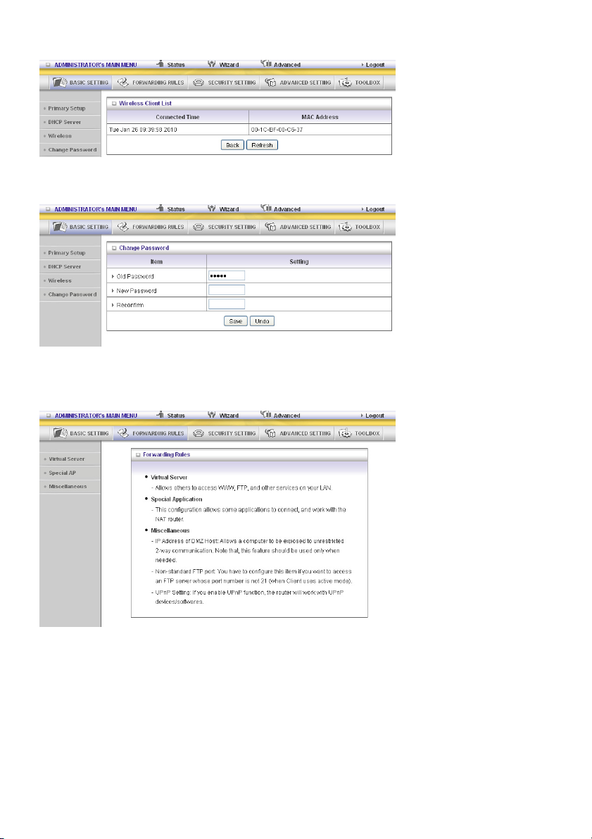
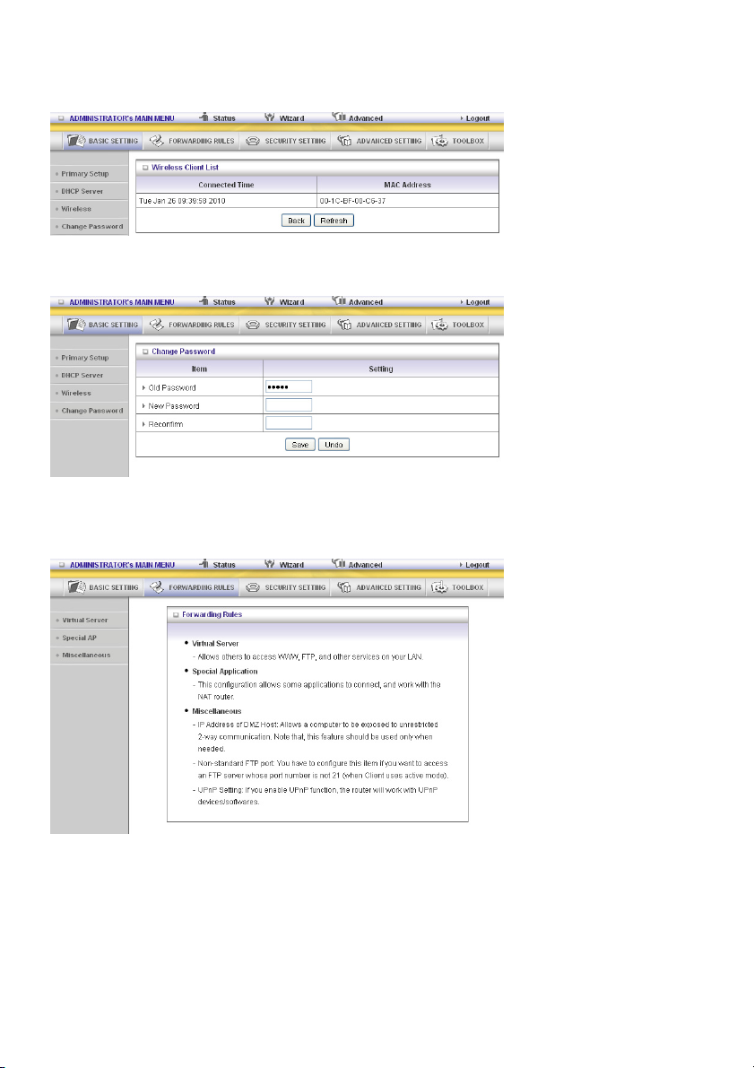
Wireless Client List
Change Password
You can change the password here. We strongly recommend to change the system password for
security reasons.
5.2 Forwarding Rules
25
Page 26
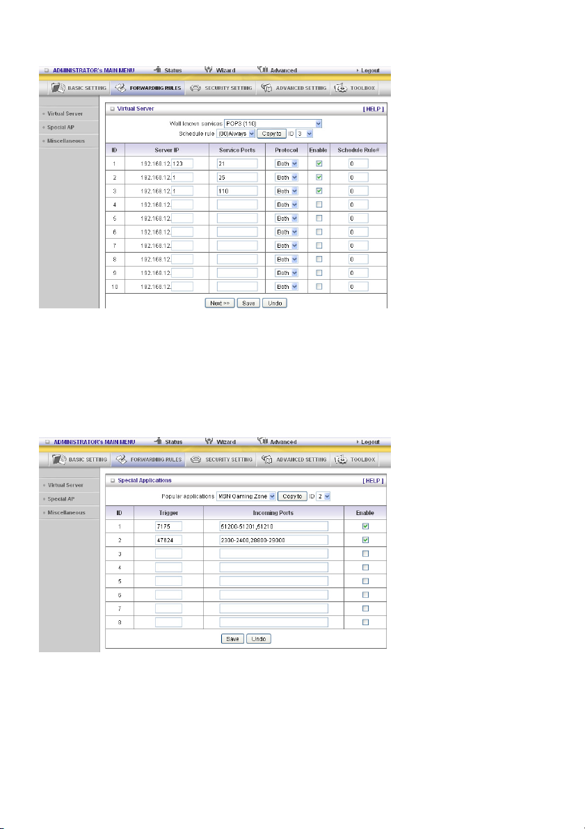
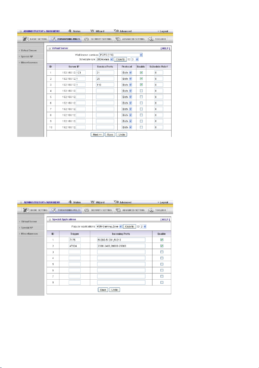
Virtual Server
The NAT firewall of this product filters out unrecognized packets to protect your Intranet, so all hosts
behind this product are invisible to the outside world. If you wish, you can make some of them
accessible by enabling the Virtual Server mapping.
A virtual server is defined as a Service Port, and all requests to this port will be redirected to the
computer specified by the Server IP. The Virtual Server can work with Schedule Rules, and gives the
user more flexibility on access control. For details, please refer to Schedule Rule.
Special AP
Some applications require multiple connections, like Internet games, video conferencing, Internet
telephony, etc. Because of the firewall function, these applications cannot work with a pure NAT router.
The Special Applications feature allows some of these applications to work with this product. If the
mechanism of Special Applications fails to make an application work, try setting your computer as the
DMZ host instead.
1. Trigger: the outbound port number issued by the application.
2. Incoming Ports: when the trigger packet is detected, the inbound packets sent to the specified port
numbers are allowed to pass through the firewall.
26
Page 27
This product provides some predefined settings. Select your application and click Copy to add the
predefined setting to your list.
Note! Only one PC can use a Special Application tunnel.
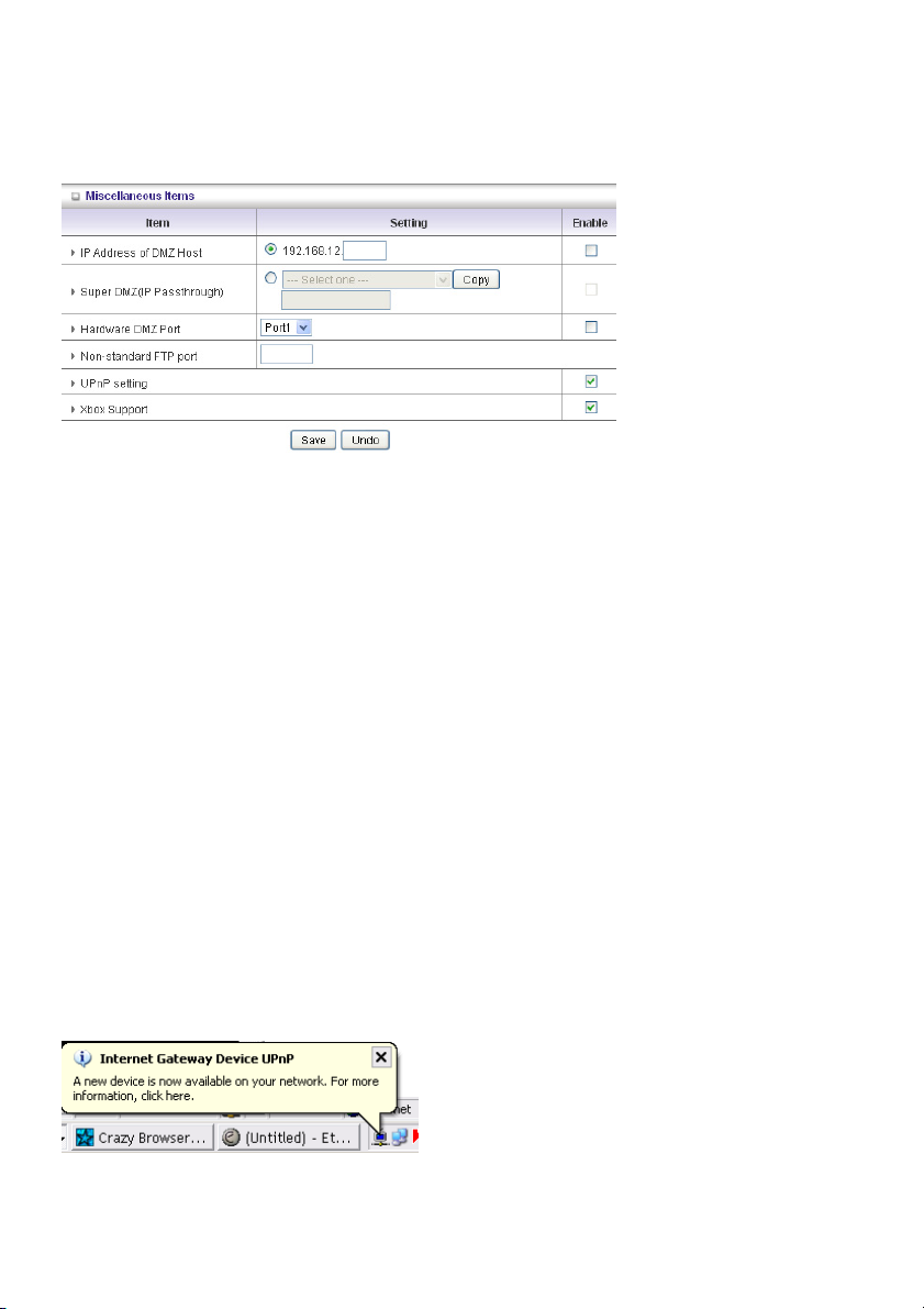
Miscellaneous Items
IP Address of DMZ Host
DMZ (Demilitarized Zone) Host is a host without the protection of firewall. It allows a computer to
participate in an unrestricted 2-way communication for Internet games, video conferencing, Internet
telephony and other special applications.
NOTE: This feature should be used only when needed.
Super DMZ (IP Passthrough)
The client must be set in Super DMZ and the DHCP server assigns a global IP which is the same with
WAN IP of this device. This client also can access the local client. This client behind NAT can use
various applications without limitation.
Hardware DMZ Port
This feature can let the device get Global IP from ISP directly. Some devices, such as an STB or an
MOD, should work via the assigned port.
Non-standard FTP port
You have to configure this item if you want to access an FTP server whose port number is not 21. This
setting will be lost after rebooting.
Xbox Support
The Xbox is a video game console produced by Microsoft Corporation. Please enable this function
when you play games.
UPnP Setting
The device also supports this function. If the OS supports this function enable it, like Windows XP.
When the user receives an IP from the device anicon as below will be displayed:
27
Page 28
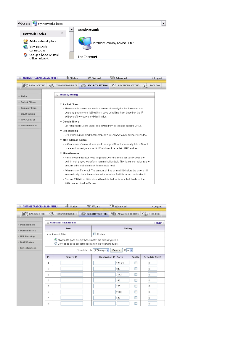
5.3 SECURITY SETTING
Packet Filters
28
Page 29
Packet Filter enables you to control what packets are allowed to pass the router. Outbound filter applies
on all outbound packets. However, inbound filter applies on packets that are destined to virtual servers
or DMZ host only. You can select one of the two filtering policies:
1. Allow all to pass except those that match the specified rules
2. Deny all to pass except those that match the specified rules
You can specify 8 rules for each direction: inbound or outbound. For each rule, you can define the
following:
• Source IP address
• Source port address
• Destination IP address
• Destination port address
• Protocol: TCP or UDP or both.
• Use Rule#
For source or destination IP address, you can define a single IP address (4.3.2.1) or a range of IP
addresses (4.3.2.1-4.3.2.254). If no prefix has been added, all port addresses will apply.
For source or destination port, you can define a single port (80) or a range of ports (1000-1999). Add
prefix "T" or "U" to specify TCP or UDP protocol. For example, T80, U53, U2000-2999. No prefix
indicates both TCP and UDP are defined. An empty implies all port addresses. Packet Filter can work
with Schedule Rules, and give user more flexibility on access control. For details, please refer to
Schedule Rule.
Each rule can be enabled or disabled individually.
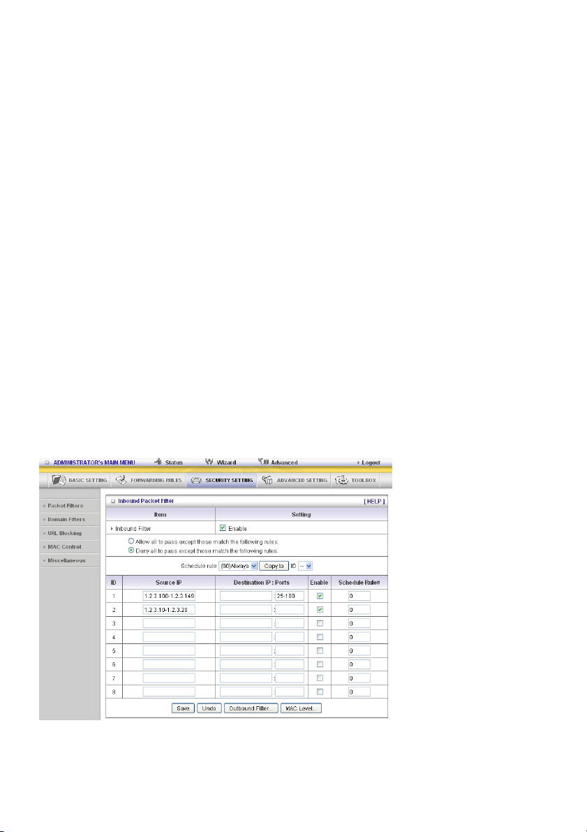
Inbound Filter:
To enable Inbound Packet Filter click the check box next to Enable in the Inbound Packet Filter
field.
Suppose you have SMTP Server (25), POP Server (110), Web Server (80), FTP Server (21), and News
Server (119) defined in Virtual Server or DMZ Host.
Example 1:
(1.2.3.100-1.2.3.149) Remote hosts are allowed to send mail (port 25), and browse the Internet
(port 80)
(1.2.3.10-1.2.3.20) Remote hosts can do everything (block nothing)
Others are all blocked.
29
Page 30
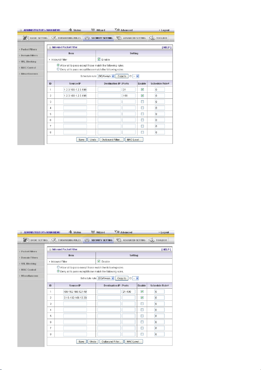
Example 2:
(1.2.3.100-1.2.3.119) Remote hosts can do everything except read net news (port 119) and transfer
files via FTP (port 21) behind router server.
Others are all allowed.
After Inbound Packet Filter setting is configured, click the Save button.
Outbound Filter:
To enable Outbound Packet Filter click the check box next to Enable in the Outbound Packet Filter
field.
Example 1:
Router LAN IP is 192.168.12.254
30
Page 31

(192.168.12.100-192.168.12.149) Located hosts are only allowed to send e-mail (port 25), receive
e-mail (port 110), and browse the Internet (port 80); port 53 (DNS) is necessary to resolve the domain
name.
(192.168.12.10-192.168.12.20) Located hosts can do everything (block nothing)
Others are all blocked.
Example 2:
Router LAN IP is 192.168.0.1
(192.168.12.100 and 192.168.12.119) Located hosts can do everything except read net news (port 119)
and transfer files via FTP (port 21)
Others are allowed
After Outbound Packet Filter setting is configured, click the Save button.
31
Page 32
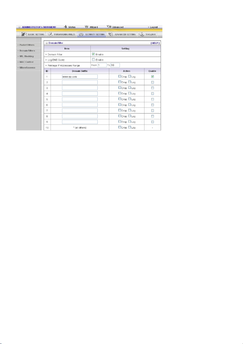
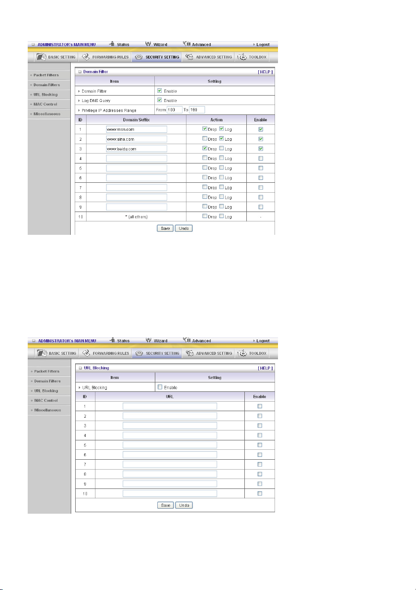
Domain Filters
Domain Filter
Lets you prevent users under this device from accessing specific URLs.
Domain Filter Enable
Check if you want to enable Domain Filter.
Log DNS Query
Check if you want to log the action when someone accesses the specific URLs.
Privilege IP Addresses Range
Setting a group of hosts and privilege these hosts to access network without restriction.
Domain Suffix
A suffix of URL to be restricted. For example, “.com”, “xxx.com”.
Action
What kind of action do you want when someone is accessing the URL with the domain suffix?
Check Drop to block the access. Check Log to log the access.
Enable
Check to enable each rule.
32
Page 33
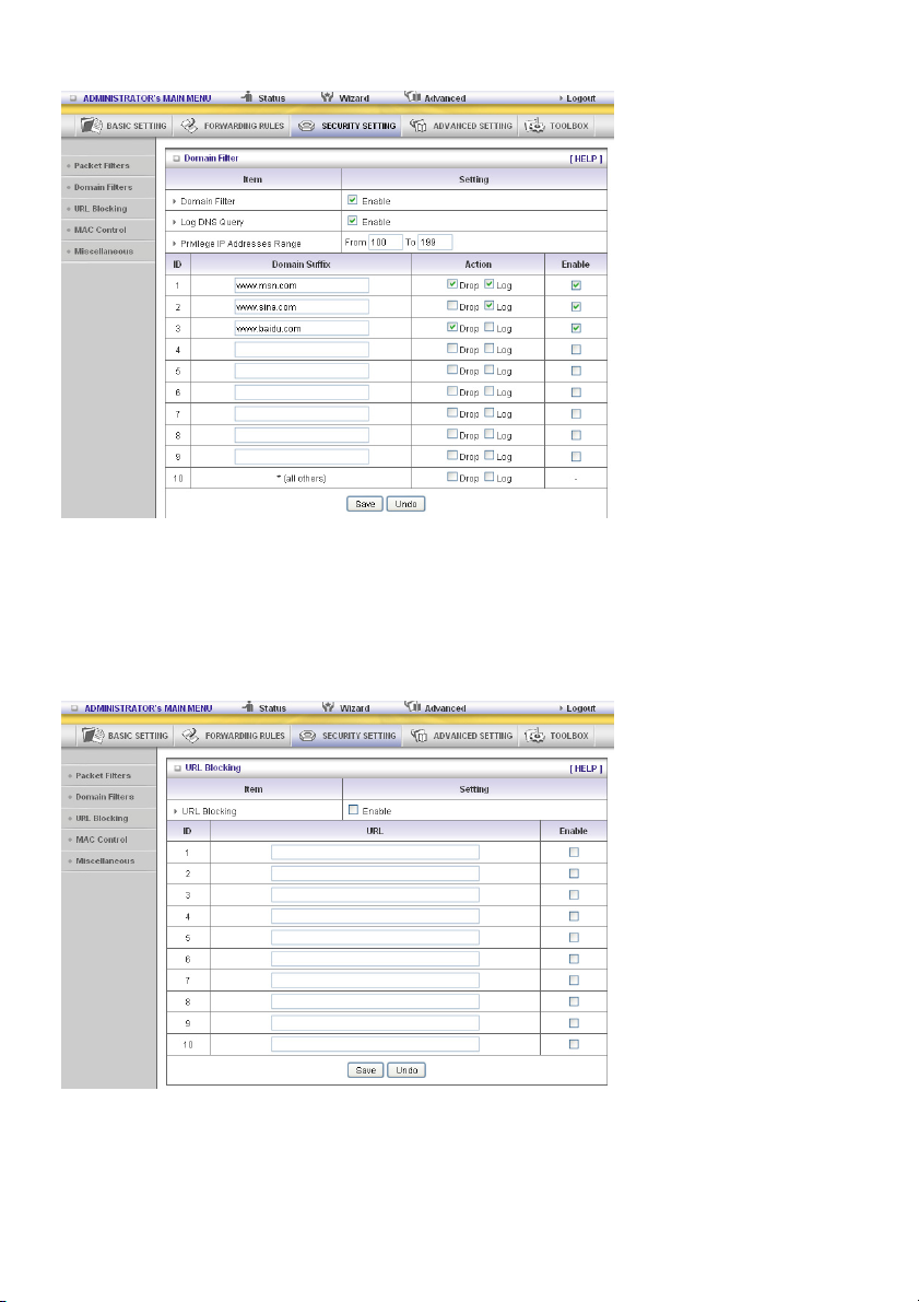
Example:
In this example:
1. The URL, including “www.msn.com”, will be blocked, and the action will be recorded on log file.
2. The URL, including “www.sina.com”, will not be blocked, but the action will be recorded on log file.
3. The URL, including “www.baidu.com”, will be blocked, but the action will not be recorded on log file.
4. IP address x.x.x.1~x.x.x.99 can access Internet without restriction.
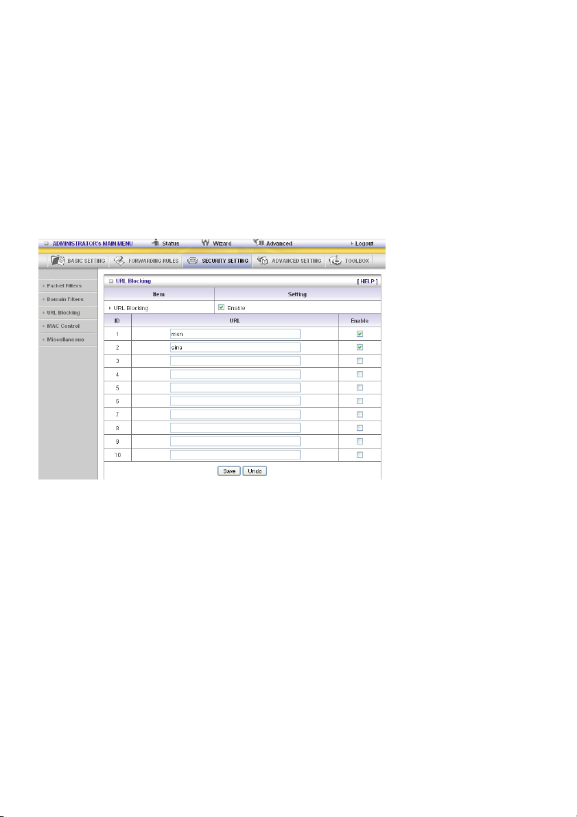
URL Blocking
URL Blocking will block LAN computers to connect to pre-defined Websites.
The major difference between “Domain Filter” and “URL Blocking” is that Domain Filter requires the
user to input suffix (like .com or .org, etc.), while URL Blocking requires the user to input a keyword only.
In other words, Domain Filter can block specific websites, while URL Blocking can block hundreds of
websites by simply a keyword.
33
Page 34
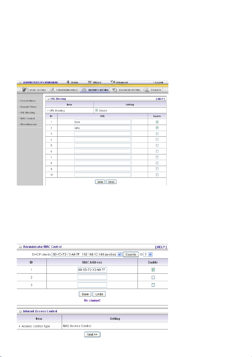
URL Blocking Enable
Check if you want to enable URL Blocking.
URL
If any part of the Website's URL matches the pre-defined word, the connection will be blocked.
For example, you can use pre-defined word “sex” to block all websites if their URLs contain pre-defined
word “sex”.
Enable
Check to enable each rule.
In this example:
1. URL including “msn” will be blocked, and the action will be recorded on log file.
2. URL including “sina” will be blocked, but the action will be recorded on log file
MAC Control
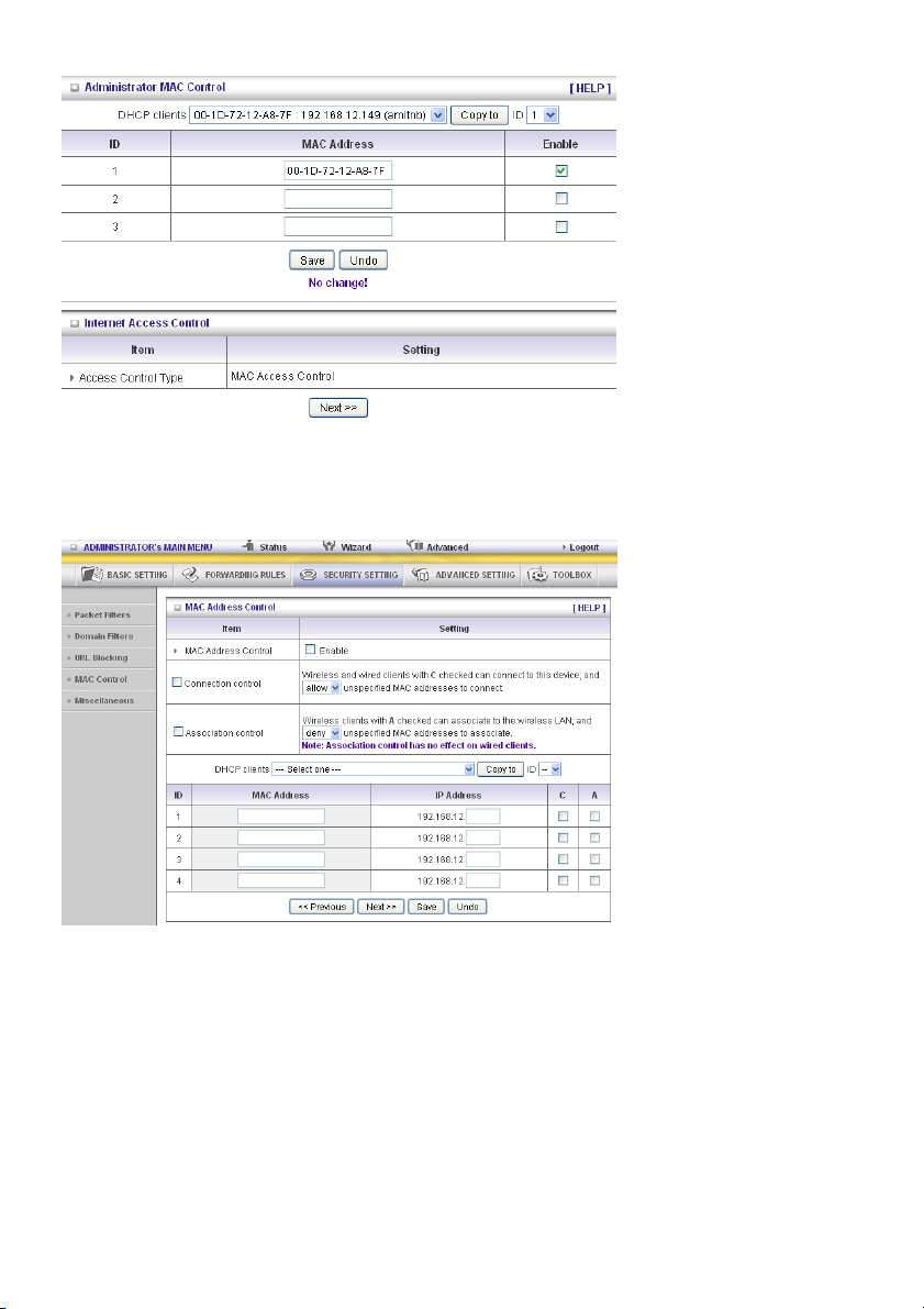
Administrator MAC Control
Regardless of the MAC access configuration of the administrator, a specific MAC address can access
the device.
34
Page 35
This device can record 3 sets. When the host (must be admin) logs in to the web management, the
device will record MAC address of this host. Before this host configures the Internet Access Control, we
suggest the end-user to enable this feature first.
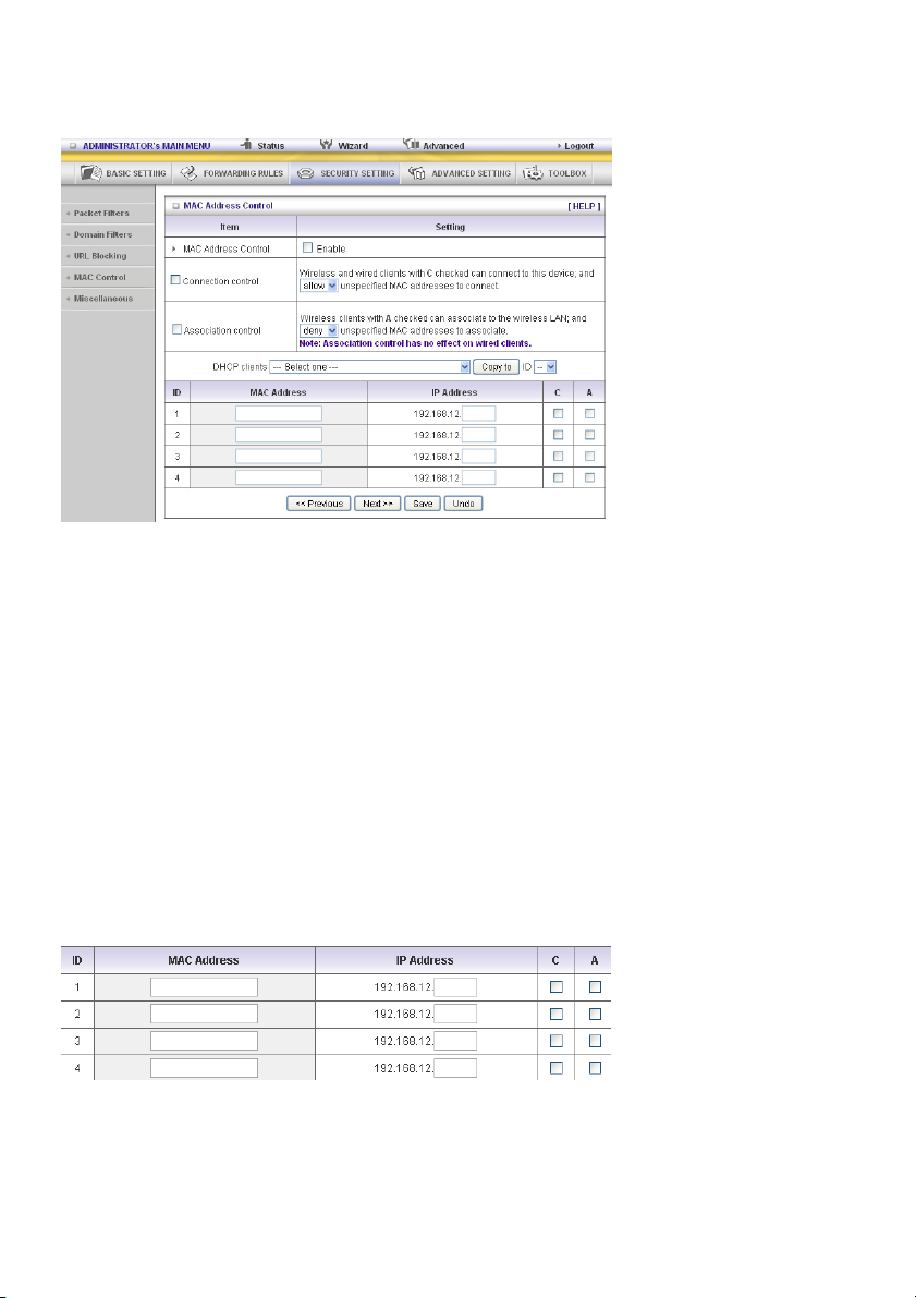
MAC Address Control allows you to assign different access rights for different users and to assign a
specific IP address to a certain MAC address.
MAC Address Control Check “Enable” to enable the “MAC Address Control”. All of the settings
in this page will take effect only when “Enable” is checked.
Connection control Check “Connection control” to enable the controlling of which wired and
wireless clients can connect to this device. If a client is denied to connect
to this device, it means the client cannot access the Internet either.
Choose “allow” or “deny” to allow or deny the clients, whose MAC
addresses are not in the “control table” (please see below), to connect to
this device.
Association control Check “Association control” to enable the controlling of which wireless
client can associate to the wireless LAN. If a client is denied to associate
to the wireless LAN, it means the client cannot send or receive any data
via this device. Choose “allow” or “deny” to allow or deny the clients,
whose MAC addresses are not in the “control table”, to associate to the
wireless LAN.
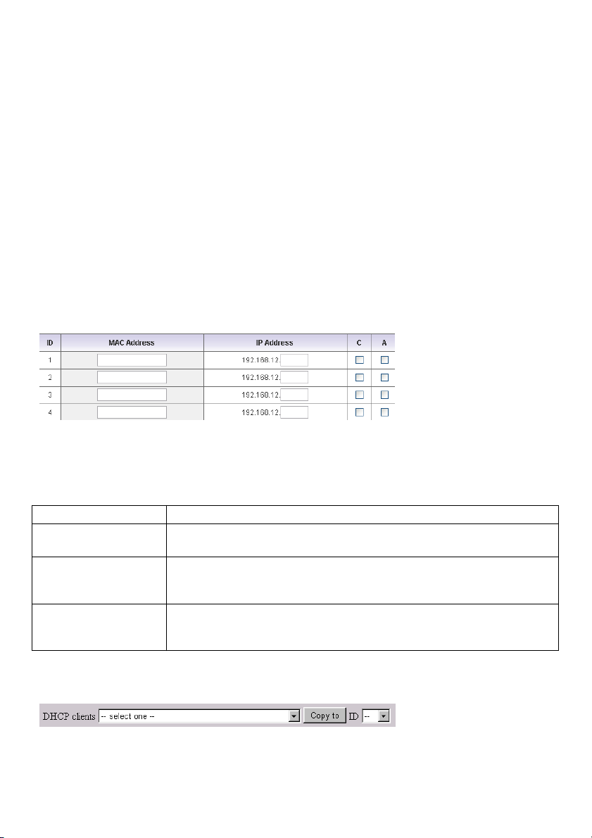
Control table
“Control table” is the table at the bottom of the “MAC Address Control” page. Each row of this table
indicates the MAC address and the expected IP address mapping of a client. There are four columns in
this table:
35
Page 36
MAC Address The MAC address indicates a specific client.
IP Address Expected IP address of the corresponding client. Leave it blank if you are
not interested in the IP address.
C When “Connection control” is selected, select “C” to allow the
corresponding client to connect to this device.
A When “Association control” is selected, select “A” to allow the
corresponding client to associate to the wireless LAN.
In this page, we provide the following combo box and button to help you to input the MAC address.
You can select a specific client in the “DHCP clients” combo box, and then click on the “Copy to” button
to copy the MAC address of the client you select to the ID selected in the “ID” combo box.
Previous page and Next
Page
To make this setup page simple and clear, we have divided the “control
table” into several pages. You can use these buttons to navigate to
different pages.
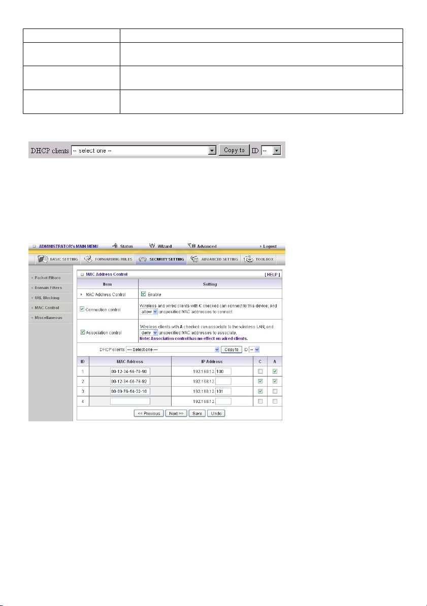
Example:
In this scenario, there are three clients listed in the control table. Clients 1 and 2 are wireless, and client
3 is wired.
1. The “MAC Address Control” function is enabled.
2. “Connection control” is enabled, and all of the wired and wireless clients not listed in the “control
table” are “allowed” to connect to this device.
3. “Association control” is enabled, and all of the wireless clients not listed in the “control table” are
“denied” to associate to the wireless LAN.
4. Clients 1 and 3 have fixed IP addresses either from the DHCP server of this device or are manually
assigned:
ID 1 – “00-12-34-56-78-90” --> 192.168.12.100
ID 3 – “00-98-76-54-32-10” --> 192.168.12.101
Client 2 will obtain its IP address from the IP address pool specified in the "DHCP Server" page or it
can use a manually assigned static IP address.
36
Page 37
If, for example, client 3 tries to use an IP address different from the address listed in the control table
(192.168.12.101), it will be denied to connect to this device.
5. Clients 2 and 3 and other wired clients with a MAC address unspecified in the control table are all
allowed to connect to this device. But client 1 is denied to connect to this device.
6. Clients 1 and 2 are allowed to associate to the wireless LAN, but a wireless client with a MAC
address not specified in the control table is denied to associate to the wireless LAN. Client 3 is a
wired client and so is not affected by Association control.
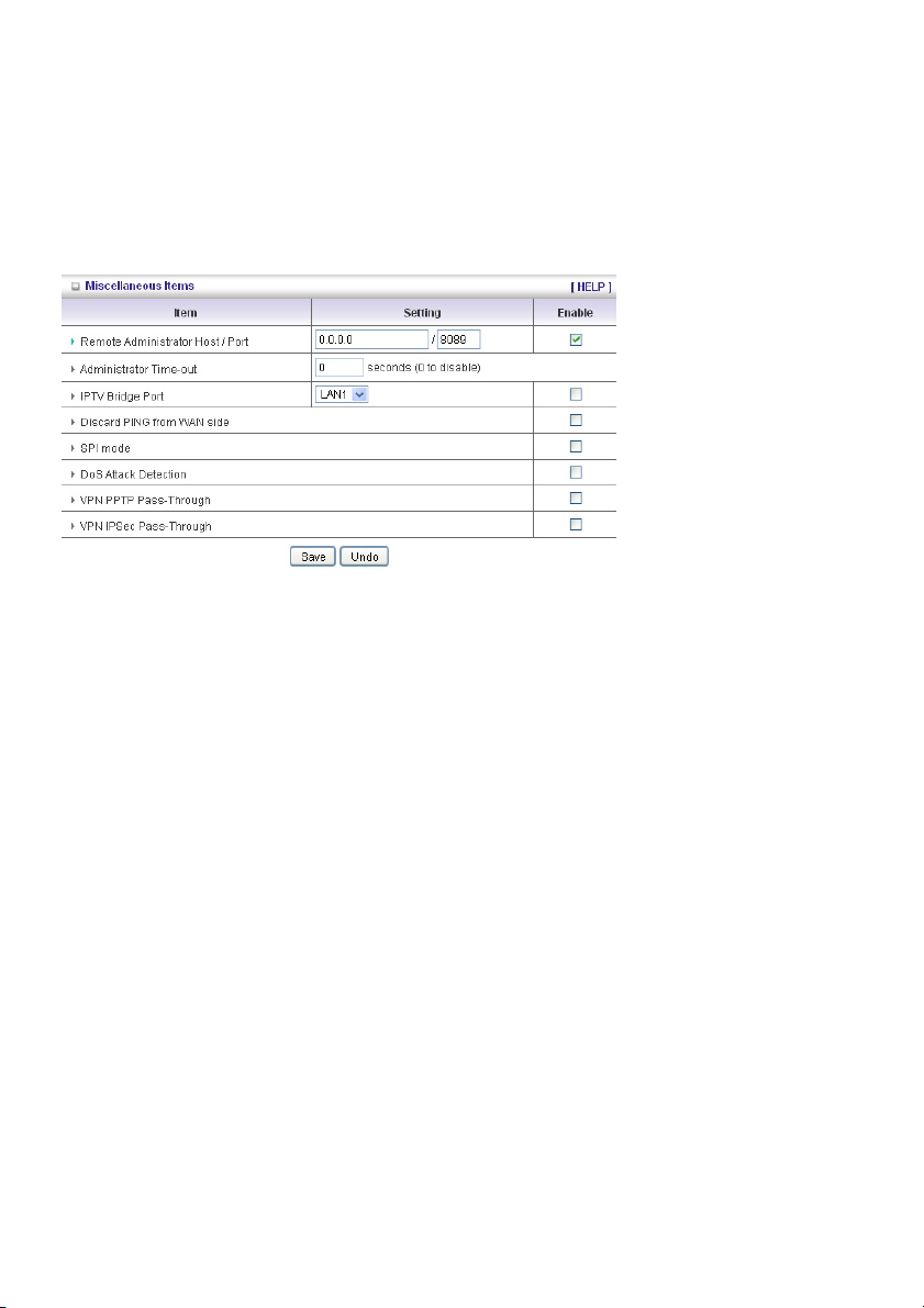
Miscellaneous Items
Remote Administrator Host/Port
In general, only Intranet users can browse the built-in web pages to perform administration tasks. This
feature enables you to perform administration tasks from a remote host. If this feature is enabled, only
the specified IP address can perform remote administration. If the specified IP address is 0.0.0.0, any
host can connect to this product to perform administration tasks. You can use subnet mask bits “/nn”
notation to specify a group of trusted IP addresses. For example, “10.1.2.0/24”.
NOTE: When Remote Administration is enabled, the web server port will be shifted to 88. You can
change the web server port to another port, too.
Administrator Time-out
The time of no activity to logout automatically. Set it to zero to disable this feature.
Discard PING from WAN side
When this feature is enabled, any host on the WAN cannot ping this product.
SPI Mode
When this feature is enabled, the router will record the packet information that passes through the
router such as an IP address, port address, ACK, SEQ number and so on. And the router will check
every incoming packet to detect if this packet is valid.
DoS Attack Detection
When this feature is enabled, the router will detect and log the DoS attack from the Internet. Currently,
the router can detect the following DoS attack: SYN Attack, WinNuke, Port Scan, Ping of Death, Land
Attack etc.
VPN PPTP and IPSec Pass-Through
Virtual Private Networking (VPN) is typically used for work-related networking. For VPN tunnels, the
router supports IPSec Pass-through and PPTP Pass-through.
37
Page 38

5.4 ADVANCED SETTING
System Time
Get Date and Time by NTP Protocol
Selected if you want to get date and time by NTP protocol.
Time Server
Select an NTP time server to consult UTC time.
Time Zone
Select the time zone where this device is located.
38
Page 39

Set Date and Time manually
Selected if you want to set date and time manually.
Function of Buttons
Sync Now: Synchronize system time with network time server
Daylight Saving: Set up where the location is.
System Log
This page supports two methods to export system logs to specific destinations: syslog (UDP) and
SMTP (TCP). The items you have to setup include:
IP Address for Syslog
Host IP of destination where syslogs will be sent to.
Check Enable to enable this function.
E-mail Alert Enable
Check if you want to enable email alert (send syslog via email).
SMTP Server IP and Port
Input the SMTP server IP and port, which are connected with ‘:’. If you do not specify the port number,
the default value is 25.
For example, “mail.your_url.com” or “192.168.1.100:26”.
Send E-mail alert to
The recipients who will receive these logs. You can assign more than 1 recipient, using ‘;’ or ‘,’ to
separate these email addresses.
39
Page 40

Dynamic DNS
To host your server on a changing IP address, you have to use the dynamic domain name service
(DDNS).
So that anyone wishing to reach your host only needs to know the name of it. Dynamic DNS will map
the name of your host to your current IP address, which changes each time you connect to your
Internet service provider.
Before you enable Dynamic DNS, you need to register an account on one of these Dynamic DNS
servers that we list in provider field.
To enable Dynamic DNS click the check box next to Enable in the DDNS field.
Next enter the appropriate information about your Dynamic DNS server.
You have to define:
Provider
Host Name
Username/E-mail
Password/Key
You will get this information when you register an account on a Dynamic DNS server.
QoS
This device supports the QoS function. The user could set up a specified upstream connection with
different priorities. There are three priorities to be selected. The packets with high priority will be
processed first.
40
Page 41

1. QoS: Quality of Service.
2. Local IP/Ports: The IP and ports that LAN side PC uses. The value 0 is not used.
3. Remote IP : Ports: The IP and ports that remote server uses. The value 0 is not used.
For example, if you want to guarantee the HTTP bandwidth, you could keep Local IP/Port as 0/0 and
Remote IP/Port as 0/80.
SNMP
In brief, SNMP, the Simple Network Management Protocol, is a protocol designed to give a user the
capability to remotely manage a computer network by polling and setting terminal values and
monitoring network events.
Enable SNMP
You must check Local or Remote or both to enable SNMP function. If Local is checked, this device will
respond to requests from LAN. If Remote is checked, this device will respond to requests from WAN.
Get Community
Setting the community of Get Request that your device will respond to.
Set Community
Setting the community of Set Request your device will accept.
IP 1, IP 2, IP 3, IP 4
Input your SNMP Management PC’s IP here. The user has to configure this device so it knows where to
send the SNMP trap message.
SNMP Version
Please select the correct SNMP version that your SNMP management software supports.
WAN Access IP Address
If the user wants to limit access to specific IP address , please input the item. The default is 0.0.0.0 and
means every IP of the Internet can get some information of the device with SNMP protocol.
Click on “Save” to store your setting or “Undo” to cancel.
41
Page 42

Routing
Routing Table allows you to determine which physical interface address to use for outgoing IP data
grams. If you have more than one router and subnet, you will need to enable the routing table to allow
packets to find the proper routing path and allow different subnets to communicate with each other.
Routing table settings are settings used to set up the functions of static routing.
Dynamic Routing
Routing Information Protocol (RIP) will exchange information about destinations for computing routes
throughout the network. Please select RIPv2 only if you have different subnets in your network.
Otherwise, please select RIPv1 if you need this protocol.
Static Routing: For static routing, you can specify up to 8 routing rules. You can enter the destination
IP Address, Subnet Mask, Gateway, Hop for each routing rule, and then enable or disable the rule by
checking or unchecking the Enable check box.
Example:
42
Page 43
Configuration on NAT Router
Destination Subnet Mask Gateway Hop Enabled
192.168.0.1 255.255.255.0 192.168.123.216 1 ˇ
192.168.0.0 255.255.255.0 192.168.123.103 1 ˇ
So if, for example, the client 3 wanted to send an IP data gram to 192.168.0.2, it would use the above
table to determine that it had to go via 192.168.123.103 (a gateway),
And if it sends packets to 192.168.1.11 it will go via 192.168.123.216
Each rule can be enabled or disabled individually.
After Routing Table setting is configured, click the Save button.
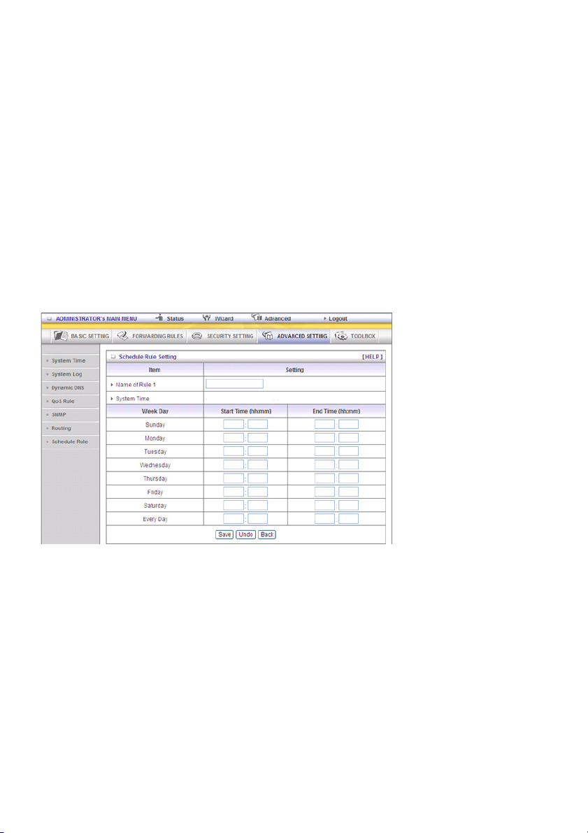
Schedule Rule
You can set the schedule time to decide which service will be turned on or off. Select the “enable” item.
Press “Add New Rule”
You can write a rule name and set which day and what time should be scheduled by filling in the fields
“Start Time” and “End Time”.The following example configures “ftp time” as everyday 14:10 to 16:20
Schedule Enable
Select if you want to enable the scheduler.
Edit
To edit the schedule rule.
Delete
To delete the schedule rule and the rule # of the rules behind the deleted one will decrease by one
automatically.
Schedule rule can be applied to virtual server and packet filter, for example:
Example 1: Virtual Server – Apply Rule#1 (ftp time: everyday 14:20 to 16:30)
43
Page 44

Example 2: Packet Filter – Apply Rule#1 (ftp time: everyday 14:20 to 16:30).
44
Page 45

5.5 TOOLBOX
View Log
You can view the system log by clicking the View Log button
Firmware Upgrade
45
Page 46

You can upgrade the firmware by clicking the Firmware Upgrade button.
5.6 Backup Setting
You can backup your settings by clicking the Backup Setting button and save it as a bin file. Once you
want to restore these settings, please click the Firmware Upgrade button and use the bin file you
saved.
Reset to default
You can also reset this product to factory default by clicking the Reset to default button.
You can also reboot this product by clicking the Reboot button.
Miscellaneous Items
MAC Address for Wake-on-LAN
Wake-on-LAN is a technology that enables you to power up a networked device from a distance. In
order to enjoy this feature, the target device must be Wake-on-LAN-enabled and you have to know the
46
Page 47

MAC address of this device, say 00-11-22-33-44-55. Click “Wake up” so that the router will send the
wake-up frame to the target device immediately.
Domain Name or IP Address for Test
Allows you to configure an IP, and ping the device. You can ping a specific IP to test whether it is alive.
Safety precautions:
To reduce risk of electric shock, this product should ONLY be
opened by an authorised technician when service is required.
Disconnect the product from mains and other equipment if a
problem should occur. Do not expose the product to water or
moisture.
Maintenance:
Clean only with a dry cloth. Do not use cleaning solvents or abrasives.
Warranty:
No guarantee or liability can be accepted for any changes and modifications of the product or damage
caused due to incorrect use of this product.
General:
- Designs and specifications are subject to change without notice.
- All logos, brands or brand logos and product names are trademarks or registered trademarks of their
respective holders and are hereby recognised as such.
- This manual was produced with care. However, no rights can be derived. König Electronic can not
accept liability for any errors in this manual or their consequences.
- Keep this manual and packaging for future reference.
Attention:
This product is marked with this symbol. It means that used electrical and electronic products
should not be mixed with general household waste. There is a separate collections system for
these products.
47
Page 48
DEUTSCH
WLAN-Router
1) HARDWAREKONFIGURATION
CMP-WNROUT50
Antenne
Netzteilans
chluss
Auto MDI/MDIX RJ-45 Anschlüsse
Tastet beim Anschluss an das Ethernet
automatisch die WAN und LAN Typen ab
Status LED WAN LED WLAN LED
Rückstelltaste
LAN1~LAN4 LEDs
2 in1 Taste
1. WPS
2. WLAN EIN
48
Page 49

LED ANZEIGEN
LED Status Beschreibung
Status Grün blinkend Gerätestatus funktioniert
WAN LED
LAN LED
WLAN LED
Grün RJ45 Kabel ist eingesteckt
Grün blinkend Datenzugriff
Grün RJ45 Kabel ist eingesteckt
Grün blinkend Datenzugriff
Grün WLAN ist eingeschaltet
Grün blinkend Datenzugriff
Schnell grün blinkend Gerät befindet sich im WPS PBC Modus
Dunkelgrün WLAN ist deaktiviert
TASTEN DEFINITION
Beschreibung
1. Wenn das WLAN ausgeschaltet ist, drücken Sie diese Taste ca. 1 Sekunde
WPS
Zurücksetzen Für 6 Sekunden gedrückt halten, um auf die Werkseinstellungen zurückzusetzen
lang, um den „WLAN-Funk“ zu aktivieren.
2. Wenn das WLAN eingeschaltet ist, drücken Sie diese Taste ca. 1 Sekunde
lang, um die WPS-Funktion auszuführen.
49
Page 50
CMP-WNROUT55 und CMP-WNROUT60
Antenne
Netzteilanschluss
Status LED
Auto MDI/MDIX RJ-45 Anschlüsse
Tastet beim Anschluss an das Ethernet
automatisch die WAN und LAN Typen ab
LAN1~LAN4 LEDs
WAN LED
WLAN LED
CMP-WNROUT55
3 in1 Taste
1. WPS
2. WLAN EIN
3. Zurücksetzen
CMP-WNROUT60
2 in1 Taste
1. WPS
2. WLAN EIN
50
Page 51

LED ANZEIGEN
LED Status Beschreibung
Status Grün blinkend Gerätestatus funktioniert
WAN LED
LAN LED
WLAN LED
Grün RJ45 Kabel ist eingesteckt
Grün blinkend Datenzugriff
Grün RJ45 Kabel ist eingesteckt
Grün blinkend Datenzugriff
Grün WLAN ist eingeschaltet
Grün blinkend Datenzugriff
Schnell grün blinkend Gerät befindet sich im WPS PBC Modus
Dunkelgrün WLAN ist deaktiviert
TASTEN DEFINITION
Beschreibung
CMP-WNROUT55
Wenn das WLAN eingeschaltet ist, drücken Sie diese Taste (ca. 1 Sekunde lang),
um die WPS-Funktion auszuführen
WPS
WLAN ist
eingeschaltet (nur
CMP-WNROUT55)
Zurücksetzen
CMP-WNROUT60
1. Wenn WLAN ausgeschaltet ist, drücken Sie diese Taste (ca. 1 Sekunde lang),
um den „WLAN-Funk“ zu aktivieren
2. Wenn das WLAN eingeschaltet ist, drücken Sie diese Taste (ca. 1 Sekunde
lang), um die WPS-Funktion auszuführen
Wenn WLAN ausgeschaltet ist, drücken Sie diese Taste (ca. 1 Sekunde lang), um
den „WLAN-Funk“ zu aktivieren
CMP-WNROUT55
1. Drücken Sie diese Taste, um das Gerät einzuschalten
2. Drücken und halten Sie diese Taste ca. 3-4 Sekunden lang, um das Gerät auf
die Standardeinstellungen zurückzusetzen, dann blinkt die Status LED jede
Sekunde im Normalstatus
Hinweis: Wenn die Status LED sehr schnell blinkt, bedeutet dies, dass die Taste
zu lang gedrückt wurde. Bitte versuchen Sie es erneut
CMP-WNROUT60
Drücken und halten Sie die Taste 6 Sekunden lang, um das Gerät auf die
Standardeinstellungen zurückzusetzen, lassen Sie die Taste dann los, wenn das
Gerät gleichzeitig arbeitet
51
Page 52
2) BEDIENUNG
Schritt 1: Stecken Sie das Ethernet Kabel in
den LAN Anschluss:
Stecken Sie das Ethernet Patchkabel in den
LAN-Anschluss an der Rückseite des Routers
ein und verwenden Sie einen verfügbaren
Ethernetanschluss am Netzwerkadapter, um das
Gerät zu konfigurieren.
Schritt 2: Stecken Sie das Ethernet
Patchkabel in den WAN-Anschluss:
Stecken Sie das Ethernet Patchkabel des DSL
Modems in den verkabelten WAN-Anschluss an
der Rückseite des Routers ein.
Schritt 3: Schalten Sie den Router ein:
Schließen Sie das Netzteil an den Empfänger auf
der Rückseite Ihres Routers an.
Schritt 4: Stellen Sie die Einrichtung fertig.
52
Page 53

Legen Sie die CD in das CD-Laufwerk Ihres PCs ein. Das Programm AutoRun wird automatisch
ausgeführt. Klicken Sie dann auf das Symbol „Einfache Einrichtung“ für dieses Dienstprogramm.
Konfigurieren Sie die Einstellungen mit den folgenden Schritten:
2.1
Wählen Sie die richtige Sprache aus und
klicken Sie dann auf „Next“, um fortzufahren.
2.2 Installationsmodus
Sie können den Assistentenmodus
auswählen, um die Einrichtung Schritt für
Schritt zu durchlaufen oder den erweiterten
Modus zu starten, um die
Netzwerkeinstellungen des Routers zu
diagnostizieren.
53
Page 54
2.3 Erweiterter Einrichtungsmodus.
Prüfen Sie den PC, Router oder die
Internetsymbole, um den Status Ihres PCs,
Routers oder des Internets zu sehen.
2.4 Installation mit dem Schnellassistenten
1. Prüfen Sie, ob der Router eingeschaltet ist.
2. Prüfen Sie, ob die Netzwerkkarte mit dem
LAN Anschluss des Routers verbunden ist.
3. Prüfen Sie, ob Ihr Netzwerkadapter eine
IP-Adresse hat.
Klicken Sie auf „Next“, um fortzufahren.
2.5 WLAN-Einstellungen
Geben Sie die SSID, die Kanal- und
Sicherheitsoptionen ein und klicken Sie dann
auf „Next“, um fortzufahren.
54
Page 55
2.6 Automatische Erkennung WAN-Dienst.
Klicken Sie auf „Next“, um fortzufahren.
Deaktivieren Sie diese Funktion, indem Sie
die Funktion „Let me select WAN service by
myself“ anklicken.
Hinweis: Diese Funktion unterstützt nur die
Erkennung der dynamischen und PPPoE
WAN-Dienste.
Beispiel: der dynamische WAN-Typ wurde
erkannt.
Nach Erkennung ist der Router einsatzbereit.
2.7 Manuelle Auswahl WAN-Dienst.
Wählen Sie im manuellen Modus ein Symbol
aus und klicken Sie auf „Next“, um
fortzufahren.
55
Page 56

2.8 Einstellungen übernehmen oder
ändern.
Klicken Sie auf „Next“, um die Einstellungen
anzuwenden und den Vorgang fortzusetzen.
Klicken Sie auf „Modify Settings“, um die
Einstellungen abzuändern.
2.9 Internetverbindung testen.
Testen Sie den WAN Netzwerkdienst. Klicken
Sie auf „Next“, um fortzufahren.
Sie können diesen Schritt ignorieren,
indem Sie „Ignore Test“ auswählen.
2.10 Einrichtung ist fertiggestellt.
Das EzSetup ist fertiggestellt. Sie können jetzt
den Standard-Web-Browser öffnen, um die
erweiterten Einstellungen des Routers zu
konfigurieren.
Klicken Sie auf „Finish“, um die Installation
fertigzustellen.
56
Page 57
3.) KONFIGURATION DES ASSISTENTEN
Geben Sie die IP Adresse ein
(http://192.168.0.1)
Geben Sie das Passwort ein, das
Standard-Passwort lautet „admin“ und klicken
Sie anschließend die „Login“ Taste.
Wählen Sie „Wizard“ (Assistent) für einfache
Grundeinstellungen aus.
Drücken Sie „Next“, um den Assistenten zu
starten.
Schritt 1:
Richten Sie Ihr System-Passwort ein.
57
Page 58

Schritt 2:
Wählen Sie „Auto Detecting WAN Type“ aus.
Schritt 3:
Stellen Sie die LAN IP und den WAN Typ ein.
Schritt 4:
Erstellen Sie Ihre Authentifizierung und
Verschlüsselung. Wählen Sie
WPA-PSK/WPA2-PSK aus. Tragen Sie jetzt
einfach den Zugangsschlüssel ein, den Sie an
der Unterseite des Routers finden.
58
Page 59

Schritt 5:
Klicken Sie dann „Apply Setting“ an.
Das Gerät startet neu.
Schritt 6:
Klicken Sie auf „Beenden“, um den
Assistenten zu beenden. Die
Internetverbindung ist erstellt.
59
Page 60

4.) SYSTEM STATUS
Diese Option dient dazu, den Arbeitsstatus des Routers zu beobachten: WAN Status.
Wenn der WAN-Anschluss auf einer dynamischen IP zugewiesen ist, kann es sein, dass eine Taste
„Renew“ oder „Release“in der seitlichen Hinweisspalte erscheint. Klicken Sie auf diese Taste, um die IP
manuell wiederherzustellen oder freizugeben.
Statistiken des WAN: Ermöglichen Ihnen, eingehende und ausgehende Pakete zu überwachen.
60
Page 61

5.) ZUSÄTZLICHE EINSTELLUNGEN
5.1 Grundeinstellungen
Bitte wählen Sie „Advanced Setting“ aus.
Drücken Sie „Change“.
Diese Option dient in erster Linie dazu, diesen Router zu aktivieren, um ordnungsgemäß damit zu
arbeiten. Die Einstellpositionen und das Aussehen im Web hängen von dem WAN Typ ab. Wählen Sie
den richtigen WAN Typ aus, bevor Sie beginnen.
61
Page 62

1. LAN IP Adresse: die lokale IP Adresse für dieses Gerät. Die Computer an Ihrem Netzwerk müssen
die LAN IP Adresse Ihres Routers als Standard Gateway verwenden. Sie können diese bei Bedarf
ändern.
2. WAN Typ: WAN Anschlusstyp Ihres Internet-Provider. Klicken Sie auf die Ändern-Taste, um aus den
folgenden Optionen die Richtige auszusuchen:
A. Statische IP Adresse: Internet-Provider weist Ihnen eine statische IP Adresse zu.
B. Dynamische IP Adresse: Sie erhalten automatisch eine IP Adresse vom Internet-Provider.
C. PPP over Ethernet: Einige Internet-Provider machen den Gebrauch von PPPoE erforderlich, um
deren Dienste zu nutzen.
D. PPTP: Einige Internet-Provider machen den Gebrauch von PPTP erforderlich, um deren Dienste
zu nutzen.
F. L2TP: Einige Internet-Provider machen den Gebrauch von L2TP erforderlich, um deren Dienste
zu nutzen
Statische IP Adresse: Internet-Provider weist Ihnen eine statische IP Adresse zu:
WAN IP Adresse, Subnet Mask, Gateway, Primary und Secondary DNS: Geben Sie die richtigen
Einstellungen ein, die Sie von Ihrem Internet-Provider erhalten.
62
Page 63

Dynamische IP Adresse: Sie erhalten automatisch eine IP Adresse vom Internet-Provider.
Host Name: Optional. Erforderlich für einige Internet-Provider, z.B. @Home.
IP Adresse für immer erneuern: Diese Funktion erlaubt es diesem Router Ihre IP Adresse automatisch
zu erneuern, wenn die Lease-Zeit abläuft - auch wenn das System im Leerlauf ist.
PPP over Ethernet: Einige Internet-Provider machen den Gebrauch von PPPoE erforderlich, um
deren Dienste zu nutzen.
PPPoE Account und Passwort: Das Konto und Passwort, das Ihnen von Ihrem Internet-Provider
zugewiesen wurde. Zur Sicherheit erscheint dieses Feld leer. Wenn Sie Ihr Passwort nicht ändern
möchten, lassen Sie das Feld leer.
PPPoE Service Name: Optional. Geben Sie den Service-Namen ein, wenn es Ihr Internet-Provider
erforderlich macht. Anderenfalls, lassen Sie dieses Feld leer.
Maximum Idle Time: Die Zeitdauer der Inaktivität, bevor Ihre PPPoE Sitzung geschlossen wird.
Stellen Sie es auf Null oder ermöglichen Sie automatisches Neuverbinden, um diese Funktion zu
deaktivieren.
Maximale Übertragungseinheit (MTU): Die meisten ISP bieten den Anwendern einen MTU-Wert. Der
gebräuchlichste MTU-Wert ist 1492.
Anschlusssteuerung: Es können 3 Modi ausgewählt werden:
Verbindung bei Bedarf: Das Gerät verbindet sich mit dem Internet-Provider, wenn die Clients
ausgehende Pakete senden.
Automatisches Neuverbinden (immer eingeschaltet): Das Gerät verbindet sich mit dem
Internet-Provider, bis die Verbindung erstellt ist.
Manuell: Das Gerät erstellt keine Verbindung, bis jemand die Verbinden-Taste auf der Statusseite
anklickt.
63
Page 64
PPTP: Einige Internet-Provider machen den Gebrauch des PPTP erforderlich, um deren Dienste
zu nutzen
Bitte prüfen Sie zuerst Ihre vom Provider zugewiesene und ausgewählte statische oder dynamische IP
Adresse.
1. Meine IP Adresse und meine Subnet Mask: Die private IP Adresse und Subnet Mask, die Ihnen vom
Internet-Provider zugewiesen wurden.
2. Server IP Adresse: Die IP Adresse des PPTP Servers.
3. PPTP Konto und Passwort: Das Konto und Passwort, das Ihnen vom Internet-Provider zugewiesen
wurde. Wenn Sie das Passwort nicht ändern möchten, lassen Sie das Feld bitte leer.
3. Anschluss ID: Optional. Geben Sie die Anschluss-ID ein, wenn Ihr Internet-Provider dies erfordert.
4. Maximale Zeit Außer Betrieb: Die Zeit ohne Aktivität, um Ihre PPTP Sitzung zu schließen. Stellen Sie
es auf Null oder ermöglichen Sie automatisches Neuverbinden, um diese Funktion zu deaktivieren.
Wenn automatisches Neuverbinden aktiviert ist, verbindet diesen Router automatisch mit dem
Internet-Provider, nachdem das System neu gestartet wurde oder die Verbindung unterbrochen
wurde.
Anschlusssteuerung: Es können 3 Modi ausgewählt werden:
Verbindung bei Bedarf: Das Gerät verbindet sich mit dem Internet-Provider, wenn die Clients
ausgehende Pakete senden.
Automatisches Neuverbinden (immer eingeschaltet): Das Gerät verbindet sich mit dem
Internet-Provider, bis die Verbindung erstellt ist.
Manuell: Das Gerät erstellt keine Verbindung, bis jemand die Verbinden-Taste auf der Statusseite
anklickt.
64
Page 65
L2TP: Einige Internet-Provider machen den Gebrauch von L2TP erforderlich, um deren Dienste
zu nutzen
Bitte prüfen Sie zuerst Ihre vom Provider zugewiesene und ausgewählte statische oder dynamische IP
Adresse.
Zum Beispiel: Statisch verwenden
1. Meine IP Adresse und meine Subnet Mask: Die private IP Adresse und Subnet Mask, die Ihnen vom
Internet-Provider zugewiesen wurden.
2. Server IP Adresse: Die IP Adresse des PPTP Servers.
3. PPTP Konto und Passwort: Das Konto und Passwort, das Ihnen vom Internet-Provider zugewiesen
wurde. Wenn Sie das Passwort nicht ändern möchten, lassen Sie das Feld bitte leer.
3. Anschluss ID: Optional. Geben Sie die Anschluss-ID ein, wenn Ihr Internet-Provider dies erfordert.
4. Maximale Zeit Außer Betrieb: Die Zeit ohne Aktivität, um Ihre PPTP Sitzung zu schließen. Stellen Sie
es auf Null oder ermöglichen Sie automatisches Neuverbinden, um diese Funktion zu deaktivieren.
Wenn automatisches Neuverbinden aktiviert ist, verbindet diesen Router automatisch mit dem
Internet-Provider, nachdem das System neu gestartet wurde oder die Verbindung unterbrochen
wurde.
Anschlusssteuerung: Es können 3 Modi ausgewählt werden:
Verbindung bei Bedarf: Das Gerät verbindet sich mit dem Internet-Provider, wenn die Clients
ausgehende Pakete senden.
Automatisches Neuverbinden (immer eingeschaltet): Das Gerät verbindet sich mit dem
Internet-Provider, bis die Verbindung erstellt ist.
Manuell: Das Gerät erstellt keine Verbindung, bis jemand die Verbinden-Taste auf der Statusseite
anklickt.
65
Page 66
Virtual Computers (nur für statische und dynamische IP Adress-WAN-Typen)
Virtual Computer ermöglicht Ihnen die Original NAT Funktionen einzusetzen und erlaubt Ihnen, die
Eins-zu-Eins-Abbildung mehrerer globaler IP Adressen und lokaler IP Adressen.
• Globale IP: Geben Sie die von Ihrem Provider zugewiesene globale IP Adresse ein.
• Lokale IP: Geben Sie die lokale IP Adresse Ihres LAN PC entsprechend der globalen IP Adresse
ein.
• Aktivieren: Markieren Sie dieses Kästchen, um die Funktion Virtual Computer zu aktivieren.
66
Page 67

DHCP Server
Drücken Sie „More>>“
1. DHCP Server: Wählen Sie „Disable“ (Deaktivieren) oder „Enable“( Aktivieren) aus.
2. Mietzeit: Dies ist die Zeitdauer, für die der Client die IP Adresse, die ihm vom DHCP Server
zugewiesen wurde, nutzen kann.
3. IP Pool-Startadresse/ IP Pool Startadresse: Wann immer eine Anfrage gestellt wird, weist der
DHCP Server automatisch eine nicht verwendete IP Adresse aus dem IP Adress-Pool an den
anfragenden Computer zu. Sie müssen die Start- und Endadresse des IP Adressen-Pools festlegen.
4. Domain Name: Diese Information wird optional an den Client weitergeleitet.
5. Primary DNS/Secondary DNS: Diese Funktion erlaubt Ihnen DNS Server zuzuweisen
6. Primary WINS/Secondary WINS: Diese Funktion erlaubt Ihnen WINS Server zuzuweisen
7. Gateway: Die Gateway-Adresse ist die IP Adresse eines alternativen Gateway.
Diese Funktion ermöglicht Ihnen, Ihren PC an ein anderes Gateway zuzuweisen, wenn der DHCP
Server Ihrem PC eine IP anbietet.
8. DHCP Client-Liste:
67
Page 68
WLAN-Konfigurationen
Mit den Wireless Settings können Sie die WLAN-Konfigurationselemente einstellen.
Wireless Radio: Der Anwender kann die WLAN-Funktion Ein (On) oder Aus (Off) schalten.
WLAN Aus Zeitplan: Bevor der WLAN-Funk abschalten wird, überprüft das Gerät, ob die
WLAN-Station online ist, abhängig vom Zeitplan „01:00-08:30“ um die WLAN-Funktion zu deaktivieren
Network ID (SSID): Die SSID wird verwendet, um das WLAN zu erkennen. Client-Stationen können
frei verfügen über diesen Router und andere Access Points, die die gleiche SSID haben. (Die
Werkseinstellung lautet „König“)
SSID Broadcast: Der Router sendet Signale, die Informationen enthalten, inklusive SSID, so dass die
WLAN Clients wissen, wie viele AP-Geräte vorhanden sind, indem sie die Funktion im Netzwerk
absuchen. Wenn diese Funktion deaktiviert wird, können die WLAN-Clients das Gerät erkennen.
Channel: Funkkanalnummer. Die zulässigen Kanäle in Europa sind 1 – 13.
WPS (WLAN-Schutzeinrichtung)
WPS ist eine WLAN-Schutzeinrichtung, die dem WCN-NET vergleichbar ist und einen sicheren und
einfachen WLAN-Anschluss bietet.
68
Page 69
WDS (WLAN-Verteilsystem)
Der WLAN-Betrieb, wie dieser im IEEE802.11 Standard festgelegt ist, wurde zur Verfügung gestellt. Bei
Verwendung des WDS ist es möglich, sich kabellos mit Zugangspunkten zu verbinden und dabei eine
verkabelte Struktur zu Standorten zu erweitern, zu welchen eine Verkabelung nicht möglich ist oder es
nicht effizient ist, eine solche umzusetzen.
Security: Wählen Sie den Datenschutz-Algorithmus, den Sie wünschen. Durch Aktivieren der
Sicherheit können Ihre Daten geschützt werden, während diese von einer Station zur anderen
übertragen werden.
Es können verschiedene Sicherheitsarten eingesetzt werden:
WEP:
Wenn Sie die 128 oder 64 Bit WEP Schlüsselsicherheit aktivieren, wählen Sie bitte einen
einzusetzenden WEP-Schlüssel und geben Sie 26 oder 10 Hexadezimale (0, 1, 2…8, 9, A, B…F)
Zeichen ein.
802.1X
Das Kontrollkästchen wurde aktiviert, um auf die Funktion 802.1X umzuschalten. Wenn die 802.1X
Funktion aktiviert ist, muss der WLAN-Nutzer sich bei diesem Router zuerst authentifizieren, bevor er
den Netzwerkdienst verwenden kann.
RADIUS Server
IP Adresse oder Domain-Name des 802.1X Servers.
RADIUS Shared Key
Der Schlüsselwert, der von dem RADIUS Server und diesem Router gemeinsam genutzt wird. Dieser
Schlüsselwert stimmt mit dem Schlüsselwert im RADIUS Server überein.
69
Page 70
A-PSK
1. Wählen Sie Verschlüsselung und Passwort-Modus aus
Wenn Sie HEX auswählen, müssen Sie 64 hexadezimale Zeichen (0, 1, 2…8, 9, A, B…F) eingeben.
Wenn Sie ASCII auswählen, ist die Länge des Zugangsschlüssels 8 bis 63 Zeichen.
2. Geben Sie den Schlüssel (Passwort) ein, z.B. 12345678
WPA
Das Kontrollkästchen wird verwendet, um die WPA-Funktion einzuschalten. Wenn die WPA Funktion
aktiviert ist, muss der WLAN-Nutzer sich bei diesem Router zuerst authentifizieren, bevor er den
Netzwerkdienst verwenden kann. RADIUS Server IP Adresse oder Domainname des 802.1X Servers.
Wählen Sie Verschlüsselung und RADIUS Passwort-Modus aus
Wenn Sie HEX auswählen, müssen Sie 64 hexadezimale Zeichen (0, 1, 2…8, 9, A, B…F) eingeben.
Wenn Sie ASCII auswählen, ist die Länge des Zugangsschlüssels 8 bis 63 Zeichen.
70
Page 71

Der Schlüsselwert, der von dem RADIUS Server und diesem Router gemeinsam genutzt wird. Dieser
Schlüsselwert stimmt mit dem Schlüsselwert im RADIUS Server überein.
WPA2-PSK (AES)
1. Wählen Sie den Preshare Key Mode aus
Wenn Sie HEX auswählen, müssen Sie 64 hexadezimale Zeichen (0, 1, 2…8, 9, A, B…F) eingeben.
Wenn Sie ASCII auswählen, ist die Länge des Zugangsschlüssels 8 bis 63 Zeichen.
2. Geben Sie den Schlüssel (Passwort) ein, z.B. 12345678
WPA2 (AES)
Das Kontrollkästchen wird verwendet, um die WPA-Funktion einzuschalten. Wenn die WPA Funktion
aktiviert ist, muss der WLAN-Nutzer sich bei diesem Router zuerst authentifizieren, bevor er den
Netzwerkdienst verwenden kann. RADIUS Server IP Adresse oder Domainname des 802.1X Servers.
Wählen Sie den RADIUS Shared Key aus
Wenn Sie HEX auswählen, müssen Sie 64 hexadezimale Zeichen (0, 1, 2…8, 9, A, B…F) eingeben.
Wenn Sie ASCII auswählen, ist die Länge des Zugangsschlüssels 8 bis 63 Zeichen.
Der Schlüsselwert, der von dem RADIUS Server und diesem Router gemeinsam genutzt wird. Dieser
Schlüsselwert stimmt mit dem Schlüsselwert im RADIUS Server überein.
WPA-PSK/WPA2-PSK
Der Router erkennt automatisch, welchen Sicherheitstyp der Client zum Verschlüsseln verwendet.
1. Wählen Sie den Preshare Key Mode aus
Wenn Sie HEX auswählen, müssen Sie 64 hexadezimale Zeichen (0, 1, 2…8, 9, A, B…F) eingeben
Wenn Sie ASCII auswählen, ist die Länge des Zugangsschlüssels 8 bis 63 Zeichen.
2. Geben Sie den Schlüssel (Passwort) ein, z.B. 12345678
WPA/WPA2
Das Kontrollkästchen wird verwendet, um die WPA2-Funktion einzuschalten. Wenn die WPA2 Funktion
aktiviert ist, muss der WLAN-Nutzer sich bei diesem Router zuerst authentifizieren, bevor er den
Netzwerkdienst verwenden kann. RADIUS Server Der Router erkennt automatisch, welchen
Sicherheitstyp (WPA-PSK Version 1 oder 2) der Client zum Verschlüsseln verwendet.
IP Adresse oder Domain-Name des 802.1X Servers.
Wählen Sie den RADIUS Shared Key aus
Wenn Sie HEX auswählen, müssen Sie 64 hexadezimale Zeichen (0, 1, 2…8, 9, A, B…F) eingeben.
Wenn Sie ASCII auswählen, ist die Länge des Zugangsschlüssels 8 bis 63 Zeichen.
71
Page 72
Der Schlüsselwert, der von dem RADIUS Server und diesem Router gemeinsam genutzt wird. Dieser
Schlüsselwert stimmt mit dem Schlüsselwert im RADIUS Server überein.
WLAN Client Liste
Change Password
Hier können Sie das Passwort ändern. Aus Sicherheitsgründen empfehlen wir dringend das
System-Passwort zu ändern.
5.2 Weiterleitungsregeln
72
Page 73
Virtual Server
Die NAT Firewall des Routers filtert nicht erkannte Pakete aus, um Ihr Intranet zu schützen, so dass
alle Hosts hinter diesem Router nach außen hin unsichtbar sind. Wenn Sie es wünschen, können Sie
einige dieser Hosts zugänglich machen, indem Sie die Virtuelle Server Zuordnung aktivieren.
Ein virtueller Server wird als Service Port festgelegt und alle Anfragen an diesem Port werden an den,
durch die Server IP , festgelegten Computer umgeleitet. Der Virtual Server kann mit Schedule Rules
(Zeitplanregeln) arbeiten und bietet dem Anwender höhere Flexibilität bei der Zugangskontrolle.
Weitere Einzelheiten finden Sie unter Schedule Rule.
Spezielle Einsatzbereiche
Einige Einsatzbereiche machen Mehrfachanschlüsse erforderlich, wie z.B. Internetspiele,
Video-Konferenzen, Internet-Telefonie, usw. Aufgrund der Firewall-Funktion können diese
Anwendungen auf einem reinen NAT-Router nicht funktionieren. Die Funktion Special Applications
erlaubt es, dass einige dieser Anwendungen mit diesem Router funktionieren. Wenn das System der
speziellen Einsatzbereiche mit einer Anwendung nicht funktioniert, versuchen Sie stattdessen Ihren
Computer als DMZ Host einzustellen.
1. Trigger: die von der Anwendung vergebene, abgehende Portnummer.
73
Page 74

2. Incoming Ports: wenn das Trigger-Paket erkannt wird, dürfen die zu den angegebenen
Port-Nummern eingehenden Pakete die Firewall passieren.
Dieser Router bietet einige vordefinierte Einstellungen. Wählen Sie Ihre Anwendung aus und klicken
Sie auf Copy um die vordefinierten Einstellungen zu Ihrer Liste hinzuzufügen.
Hinweis! Zu jeder Zeit darf nur ein PC jeden speziellen Anwendungstunnel verwenden.
Sonstiges
IP Adresse des DMZ Host
Der DMZ (entmilitarisierte Zone) Host ist ein Host ohne den Schutz einer Firewall. Es erlaubt einem
Computer die uneingeschränkte 2-Wege-Kommunikation für Internet-Games, Video-Konferenzen,
Internet-Telefonie und andere Spezialanwendungen einzusetzen.
HINWEIS: Diese Funktion sollte nur dann verwendet werden, wenn diese gebraucht wird.
Super DMZ (IP Durchreichemodus)
Der Client muss auf Super DMZ eingestellt sein und der DHCP Server weist eine globale IP zu, welche
dieselbe ist, wie die WAN IP dieses Gerätes. Dieser Client kann auch auf den lokalen Client zugreifen.
Dieser Client hinter dem NAT kann verschiedene Anwendungen ohne Einschränkungen verwenden.
Hardware DMZ Port
Diese Funktion kann zulassen, dass das Gerät die globale IP direkt vom Internetprovider erhält. Einige
Geräte, wie z.B. Receiver, müssen über einen zugewiesenen Port arbeiten.
Non-standard FTP port
Sie müssen diese Position konfigurieren, wenn Sie auf einen FTP Server zugreifen möchten, dessen
Portnummer nicht 21 lautet. Diese Einstellung geht nach dem Neustart verloren.
Xbox Support
Die Xbox ist eine Videospielkonsole, die von der Microsoft Corporation hergestellt wird. Bitte aktivieren
Sie diese Funktion, wenn Sie Spiele spielen.
UPnP Setting
Das Gerät unterstützt auch diese Funktion. Wenn das Betriebssystem diese Funktion unterstützt,
aktivieren Sie diese wie Windows XP. Wenn der Anwender die IP von dem Gerät erhält und das Icon,
wie unten dargestellt, sieht:
74
Page 75

5.3 SICHERHEITSEINSTELLUNG
Packet Filters
75
Page 76

Der Paketfilter erlaubt Ihnen, zu kontrollieren, welche Pakete den Router passieren dürfen. Der
Ausgangsfilter wird auf alle ausgehenden Pakete angewandt. Der Eingangsfilter wird jedoch auf
Pakete angewandt, die nur für den Virtual Server oder dem DMZ Host gedacht sind. Sie können eine
der beiden Filtermethoden auswählen:
1. Lässt alle passieren, außer die, die zu den speziellen Regeln passen
2. Verweigert das Passieren allen, außer die, die zu den speziellen Regeln passen
Sie können 8 Regeln für jede Richtung festlegen: Eingehend oder ausgehend. Sie können für jede
Regel folgendes festlegen:
• Quell-IP-Adresse
• Quell-Portadresse
• Ziel-IP-Adresse
• Ziel-Portadresse
• Protokoll: TCP oder UDP oder beides.
• Regelnummer verwenden
Für die Quell- oder Ziel-IP-Adresse können Sie eine einzelne IP-Adresse (4.3.2.1) oder eine Reihe von
IP-Adressen (4.3.2.1-4.3.2.254) festlegen. Ein leeres Feld beinhaltet alle IP-Adressen.
Für den Quell- oder Zielport können Sie einen einzelnen Port (80) oder eine Reihe Ports (1000-1999)
festlegen. Vorzeichen „T“ oder „U“ hinzufügen, um das TCP oder UDP Protokoll festzulegen. Zum
Beispiel: T80, U53, U2000-2999. Kein Vorzeichen bedeutet, dass sowohl TCP, als auch UDP festgelegt
sind. Ein leeres Feld beinhaltet alle Portadressen. Der Packet Filter kann mit Schedule Rules
funktionieren und bietet dem Anwender mehr Flexibilität bei der Zugangskontrolle. Weitere Einzelheiten
finden Sie unter Schedule Rule.
Jede Regel kann einzeln aktiviert oder deaktiviert werden.
Eingangsfilter:
Um den Inbound Packet Filter zu aktivieren, klicken Sie auf das Kontrollkästchen Enable im Feld
Inbound Packet Filter.
Angenommen, Sie haben einen SMTP Server (25), POP Server (110), Webserver (80), FTP Server
(21), und News Server (119) im Virtual Server oder im DMZ Host festgelegt.
Beispiel 1:
(1.2.3.100-1.2.3.149) Remote Hosts dürfen Mails senden (Port 25) und im Internet suchen (Port 80)
(1.2.3.10-1.2.3.20) Remote Hosts können alles tun (nichts wird blockiert)
Alle anderen sind blockiert.
76
Page 77

Beispiel 2:
(1.2.3.100-1.2.3.119) Remote Hosts können alles tun, außer Netzwerk-Nachrichten lesen (Port 119)
und Dateien über FTP (Port 21) hinter dem Router Server übertragen.
Alle anderen sind erlaubt.
Nachdem die Inbound Packet Filter - Einstellung konfiguriert wurde, klicken Sie auf die Schaltfläche
Save.
Ausgangsfilter:
Um den Outbound Packet Filter zu aktivieren, klicken Sie auf das Kontrollkästchen Enable im Feld
Outbound Packet Filter.
77
Page 78

Beispiel 1:
Die Router LAN IP lautet 192.168.12.254
(192.168.12.100-192.168.12.149) Lokale Hosts dürfen nur Mails senden (Port 25), Mails empfangen
(Port 110) und im Internet suchen (Port 80); Port 53 (DNS) ist notwendig, um den Domain-Namen
aufzulösen.
(192.168.12.10-192.168.12.20) Lokale Hosts können alles tun (nichts wird blockiert)
Alle anderen sind blockiert.
Beispiel 2:
Router LAN IP lautet 192.168.0.1
(192.168.12.100 und 192.168.12.119) Lokale Hosts können alles tun, außer Netzwerk-Nachrichten
lesen (Port 119) und Dateien über FTP (Port 21) übertragen
78
Page 79

Weitere Funktionen sind zulässig
Nachdem die Einstellung für den Outbound Packet Filter konfiguriert wurde, klicken Sie auf die
Schaltfläche Save.
Domain Filter
Domain Filter
Hiermit können Sie verhindern, dass Anwender dieses Gerätes auf bestimmte URL zugreifen.
Domain Filter Enable
Prüfen Sie, ob Sie den Domain Filter aktivieren möchten.
Log DNS Query
Prüfen Sie, ob Sie die Aktion protokollieren möchten, wenn jemand auf spezielle URLs zugreift.
Privilege IP Addresses Range
Einstellen einer Gruppe von Hosts und Privilegien dieser Hosts die Netzwerk-Zugriff ohne
Einschränkung haben.
Domain Suffix
Ein Zusatz der URL, der eingeschränkt wird. Zum Beispiel „.com“, „xxx.com“.
Action
Wenn jemand auf die URL mit dem Domain Zusatz zugreift, welche Aktion möchten Sie auslösen.
Haken Sie Drop an, um den Zugriff zu blockieren. Haken Sie Log an, um den Zugriff zu protokollieren.
Enable
Anhaken, um jede Regel zu aktivieren.
79
Page 80
Beispiel:
In diesem Beispiel:
1. Die URL mit „www.msn.com“ wird blockiert und die Aktion wird in der Protokolldatei aufgezeichnet.
2. Die URL mit „www.sina.com“ wird nicht blockiert, aber die Aktion wird in der Protokolldatei
aufgezeichnet.
3. Die URL mit „www.baidu.com“ wird blockiert, aber die Aktion wird nicht in der Protokolldatei
aufgezeichnet.
4. Die IP Adresse x.x.x.1~x.x.x.99 kann ohne Einschränkung auf das Internet zugreifen.
URL Blocking
URL Blocking blockiert LAN Computer bei der Verbindung mit zuvor festgelegten Websites.
Der Hauptunterschied zwischen dem „Domain Filter“ und dem „URL Blocking“ ist, dass es der
Domainfilter erforderlich macht, dass der Anwender den Zusatz eingibt (wie z.B. .com oder .org, usw.),
während es das URL Blocking erforderlich macht, dass der Anwender lediglich einen Suchbegriff
80
Page 81
eingibt. Mit anderen Worten, der Domain Filter kann bestimmte Websites blockieren, während das URL
Blockieren Hunderten von Websites blockieren kann, alleine durch die Eingabe eines Suchbegriffs.
URL Blockieren aktiviert
Prüfen Sie, ob Sie das URL Blockieren aktivieren möchten.
URL
Wenn ein Teil der URL der Website zu dem zuvor festgelegten Wort passt, wird die Verbindung
blockiert.
Als Beispiel können Sie das zuvor festgelegte Wort „sex“ verwenden, um alle Websites zu blockieren,
deren URL das Wort „sex“ enthalten.
Aktivieren
Anhaken, um jede Regel zu aktivieren.
In diesem Beispiel:
1. Die URL mit „msn“ wird blockiert und die Aktion wird in der Protokolldatei aufgezeichnet.
2. Die URL mit „sina“ wird blockiert, aber die Aktion wird in der Protokolldatei aufgezeichnet
MAC Kontrolle
Administrator MAC Kontrolle
Gleichgültig, wie die MAC Zugangskonfiguration des Administrators lautet, bestimmte MAC können auf
das Gerät zugreifen.
81
Page 82
Dieses Gerät kann 3 Einstellungen aufzeichnen. Wenn das Host Login Web-Management (sollte Admin
sein) lautet, zeichnet das Gerät die MAC-Adresse dieses Host auf. Bevor dieser Host die
Internet-Zugriffskontrolle konfiguriert, schlagen Sie den Endanwendern vor, zuerst diese Funktion zu
aktivieren.
Die MAC Adressen-Kontrolle erlaubt Ihnen, verschiedene Zugriffsrechte für verschiedene Anwender
zuzuweisen und eine spezielle IP Adresse zu einer bestimmten MAC Adresse zuzuweisen.
82
Page 83
MAC
Adressen-Kontrollen
Haken Sie „Enable “ an, um die „ MAC Address Control“ zu aktivieren.
Alle Einstellungen auf dieser Seite werden erst wirksam, wenn
„Aktivieren“ angehakt ist.
Connection control Haken Sie „Anschlusskontrolle“ an, um die Kontrolle, welche mit Kabel
und WLAN angeschlossene Clients sich nicht mit diesem Gerät
verbinden können, zu aktivieren. Wenn ein Client abgelehnt wird, sich mit
diesem Gerät zu verbinden, bedeutet dies, dass der Client auch nicht auf
das Internet zugreifen kann. Wählen Sie „allow“ oder „deny“, um dem
Client zu ermöglichen oder zu untersagen, dessen MAC Adressen nicht
in der „Kontrolltabelle“ (siehe unten) enthalten ist, sich mit diesem Gerät
zu verbinden.
Association control Haken Sie „Verbindungskontrolle“ an, um die Kontrolle zu aktivieren,
welche WLAN Clients auf das WLAN zugreifen können. Wenn ein Client
abgelehnt wird, auf das WLAN zuzugreifen, bedeutet dies, dass dieser
Client Daten über dieses Gerät weder senden, noch empfangen kann.
Wählen Sie „allow“ oder „deny” aus, um dem Client zu ermöglichen oder
zu untersagen, dessen MAC Adressen nicht in der „Kontrolltabelle“ (siehe
unten) enthalten ist, sich mit diesem Gerät zu verbinden.
Kontrolltabelle
Die „Kontrolltabelle“ ist eine Tabelle unten auf der „MAC Address Control“ Seite. Jede Zeile dieser
Tabelle gibt die MAC Adresse und die erwartete IP Adresszuordnung eines Client an. Es gibt vier
Spalten in dieser Tabelle:
MAC Address Die MAC Adresse gibt einen speziellen Client an.
IP Address Erwartete IP Adresse des entsprechenden Client. Lassen Sie das Feld leer,
wenn Sie kein Interesse an dessen IP Adresse haben.
C Wenn „Connection control“ angehakt ist, können Sie durch Anhaken von
„C“, dem entsprechenden Client erlauben, sich an dieses Gerät
anzuschließen.
A Wenn „Association control“ angehakt ist, können Sie durch Anhaken von
„A“, dem entsprechenden Client ermöglichen, sich mit dem WLAN zu
verbinden.
Auf dieser Seite liefern wir Ihnen das folgende Kombinationsfeld und die Schaltfläche, die Ihnen
ermöglicht, die MAC Adresse einzugeben.
Sie können einen speziellen Client in dem „DHCP clients“ Kombinationsfeld auswählen und dann auf
die Schaltfläche „Copy to“ klicken, um die MAC Adresse des von Ihnen ausgewählten Client auf die
ausgewählte ID in dem „ID“ Kombinationsfeld zu kopieren.
83
Page 84
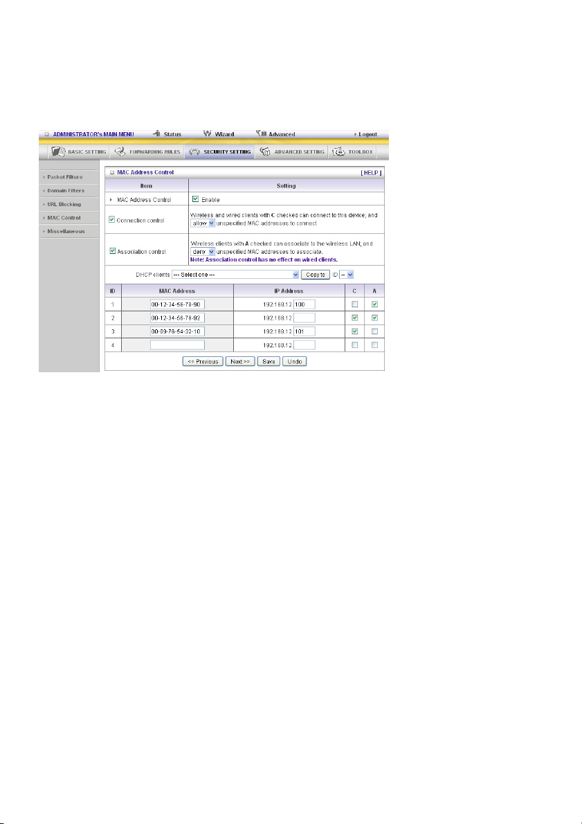
Previous/Next
(Vorherige/Nächste)
Seite
Um diese Einrichtungsseite einfach und klar zu gestalten, haben wir die
„Kontrolltabelle“ auf mehrere Seiten verteilt. Sie können diese
Schaltflächen verwenden, um zu den verschiedenen Seiten zu
navigieren.
Beispiel:
In diesem Szenario gibt es drei Clients, die in der Kontrolltabelle aufgelistet sind. Die Clients 1 und 2
arbeiten mit WLAN und Client 3 ist mit einem Kabel verbunden.
1. Die „MAC Address Control“ Funktion ist aktiviert.
2. Die „Connection control“ ist aktiviert und allen mit Kabel und WLAN angeschlossene Clients, die
nicht in der „Kontrolltabelle“ aufgelistet sind, wird „erlaubt“, sich an dieses Gerät anzuschließen.
3. Die „Association control“ ist aktiviert und allen WLAN Clients, die nicht in der
„Kontrolltabelle“ aufgelistet sind, wird die WLAN Verbindung „verweigert“.
4. Die Clients 1 und 3 haben feste IP Adressen, entweder vom DHCP Server dieses Gerätes oder
manuell zugewiesene IP Adressen:
ID 1 – „00-12-34-56-78-90“ --> 192.168.12.100
ID 3 – „00-98-76-54-32-10“ --> 192.168.12.101
Der Client 2 erhält seine IP Adresse aus dem IP Adresspool, der auf der „DHCP Server“ Seite
festgelegt ist oder kann eine manuell zugewiesene statische IP Adresse verwenden.
Wenn z.B. Client 3 versucht, eine andere IP Adresse zu verwenden, als die Adresse, die in der
Kontrolltabelle aufgelistet ist (192.168.12.101), wird ihm die Verbindung mit diesem Gerät
verweigert.
5. Die Clients 2 und 3 und andere mit Kabel angeschlossene Clients mit einer MAC Adresse, die nicht
in der Kontrolltabelle angegeben ist, haben alle die Erlaubnis, sich mit diesem Gerät zu verbinden.
Aber Client 1 wird die Verbindung mit diesem Gerät verweigert.
6. Die Clients 1 und 2 haben die Erlaubnis, sich mit dem WLAN zu verbinden, aber einem WLAN-Client
mit einer MAC Adresse, die nicht in der Kontrolltabelle angegeben ist, wird die Verbindung mit
diesem WLAN verweigert. Client 3 ist ein mit Kabel angeschlossener Client, so dass dieser nicht von
der Verbindungskontrolle betroffen ist.
84
Page 85
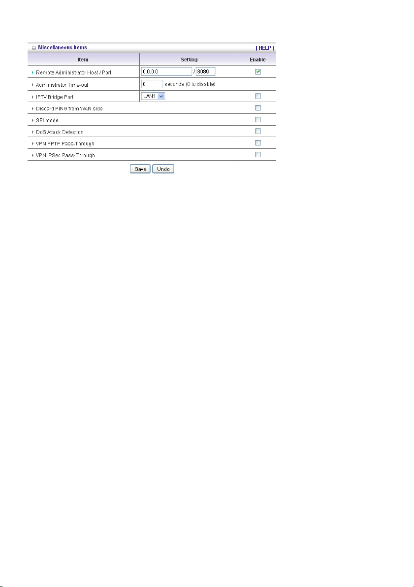
Verschiedene Positionen
Remote Administrator Host/Port
In der Regel können nur Intranet-Nutzer die integrierten Webseiten zur Durchführung von
Verwaltungsaufgaben durchsuchen. Diese Funktion ermöglicht Ihnen, Verwaltungsaufgaben von einem
Remote-Rechner auszuführen. Wenn diese Funktion aktiviert ist, kann nur die angegebene IP Adresse
Remote-Verwaltungsaufgaben durchführen. Wenn die angegebene IP Adresse 0.0.0.0 lautet, kann sich
jeder Host mit diesem Router verbinden, um Verwaltungsaufgaben durchzuführen. Sie können eine
Subnet Mask Bits „/nn“ Schreibweise verwenden, um eine Gruppe vertrauenswürdiger IP-Adressen
festzulegen. Zum Beispiel „10.1.2.0/24“.
HINWEIS: Wenn die Fernverwaltung aktiviert ist, wird der Web-Server-Port auf 88 verschoben. Sie
können den Web-Server-Port ebenfalls auf einen anderen Port abändern.
Administrator Time-out
Die Zeit ohne Aktivität bis zum automatischen ausloggen. Setzen Sie ihn auf Null, um diese Funktion
zu deaktivieren.
Discard PING from WAN side
Wenn diese Funktion aktiviert ist, kann kein Host diesen Router aus dem WAN anpingen.
SPI Mode
Wenn diese Funktion aktiviert ist, zeichnet der Router die Paketdaten auf, die durch den Router geleitet
werden, wie IP-Adresse, Portadresse, ACK, SEQ Nummer usw.. Und der Router prüft jedes
eingehende Paket, um zu erkennen, ob dieses Paket gültig ist.
DoS Attack Detection
Wenn dieses Feature aktiviert ist, erkennt und zeichnet der Router die DoS Angriffe aus dem Internet
auf. Derzeit kann der Router die folgenden DoS Angriffe erkennen: SYN Attack, WinNuke, Port Scan,
Ping of Death, Land Attack usw..
VPN PPTP und IPSec Pass-Through
Virtual Private Network (VPN) wird vorzugsweise für einen Fernzugriff auf Unternehmensnetzwerke
verwendet. Für VPN Tunnel unterstützt der Router IPSec Durchgang und PPTP Durchgang.
85
Page 86
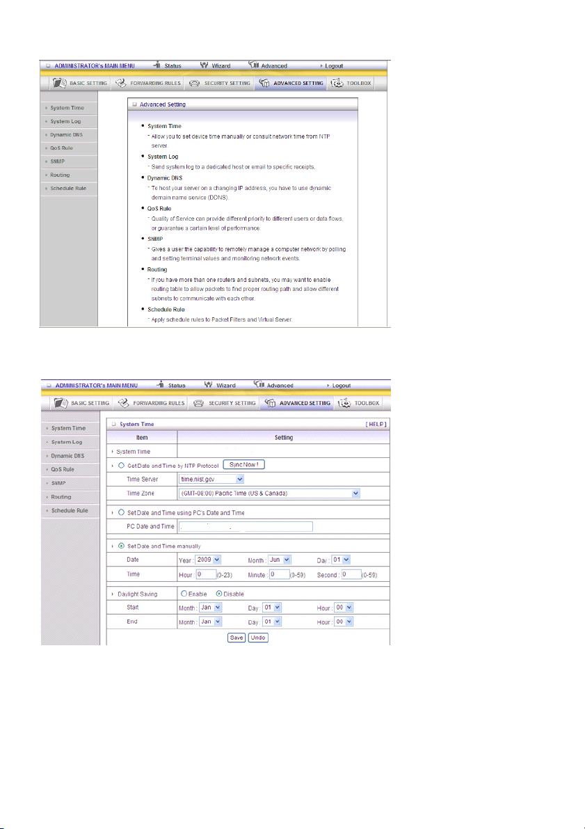
5.4 ERWEITERTE EINSTELLUNG
System Time
Get Date and Time by NTP Protocol
Wählen Sie aus, ob Sie das Datum und die Zeit vom NTP Protokoll erhalten möchten.
Time Server
Wählen Sie einen NTP Zeitserver aus, um die UTC Zeit abzufragen.
Time Zone
Wählen Sie eine Zeitzone aus, in welcher sich dieses Gerät befindet.
86
Page 87
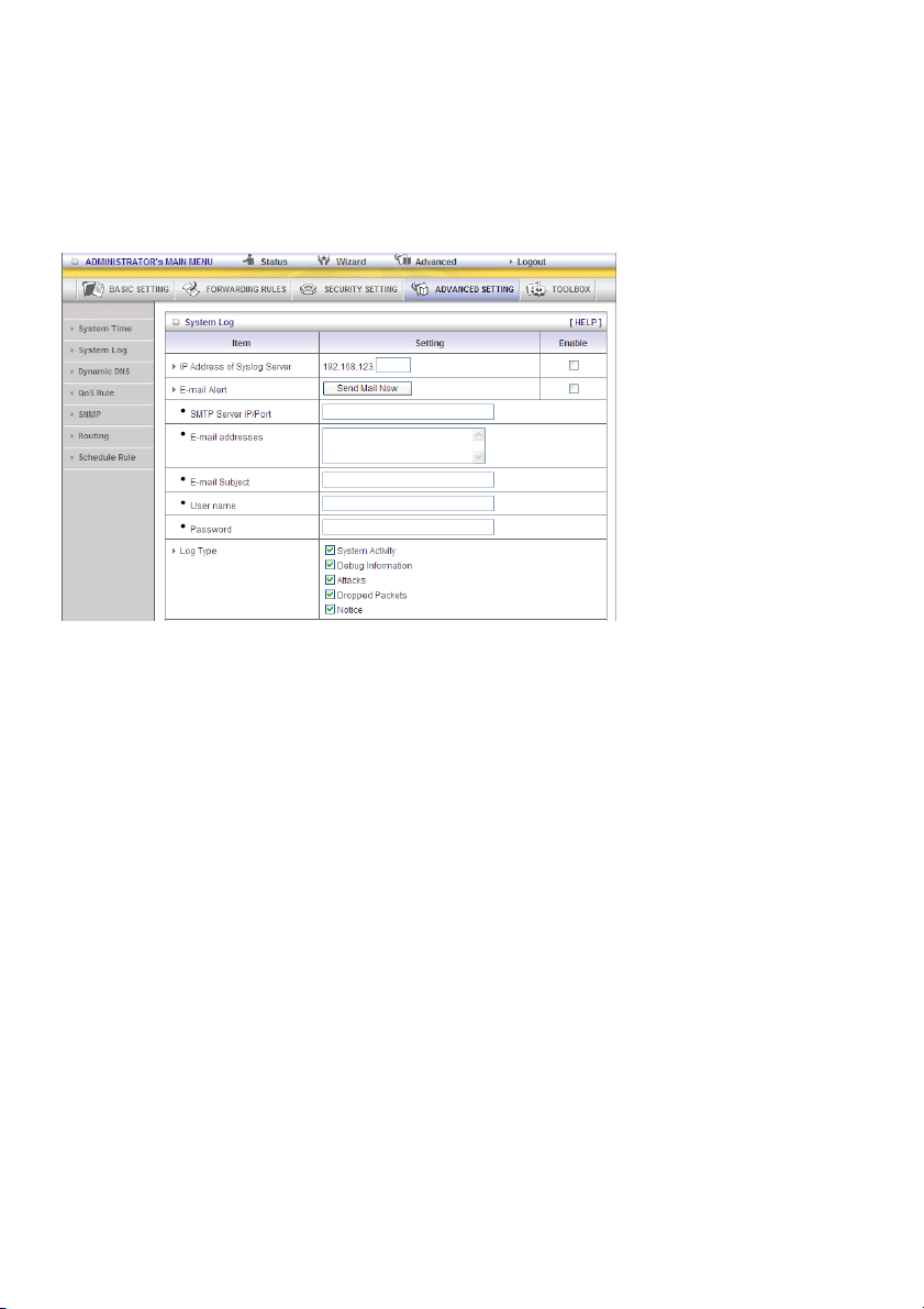
Set Date and Time manually
Wählen Sie aus, ob Sie das Datum und die Zeit manuell einstellen möchten.
Funktion und Schaltflächen
Sync Now: Synchronisieren Sie die Systemzeit mit dem Netzwerkzeitserver
Daylight Saving: Einstellung Sommerzeit
System Log
Diese Seite unterstützt zwei Methoden, um Systemprotokolle zu bestimmten Zielen mit Hilfe des
Syslog (UDP) und SMTP (TCP) durchzuführen. Die Elemente, die Ihnen für die Einrichtung zur
Verfügung stehen, umfassen:
IP Adresse für Syslog
Host IP des Ziels, zu welchem Syslog gesandt wird.
Haken Sie Enable an, um diese Funktion zu aktivieren.
E-Mail Alarm aktivieren
Haken Sie dies gegebenenfalls an, um den E-Mail Alarm zu aktivieren (Syslog per E-Mail senden).
SMTP Server IP und Port
Geben Sie die SMTP Server IP und den Port ein, die mit „:“ verbunden werden. Wenn Sie die
Portnummer nicht festlegen, lautet der Standardwert 25.
Zum Beispiel „mail.your_url.com“ oder „192.168.1.100:26“.
E-Mail Alarm senden an
Die Empfänger, die diese Protokolle erhalten. Sie können mehr als 1 Empfänger zuweisen, indem Sie
„;“ oder „,“ verwenden, um diese E-Mail Adressen voneinander zu trennen.
87
Page 88
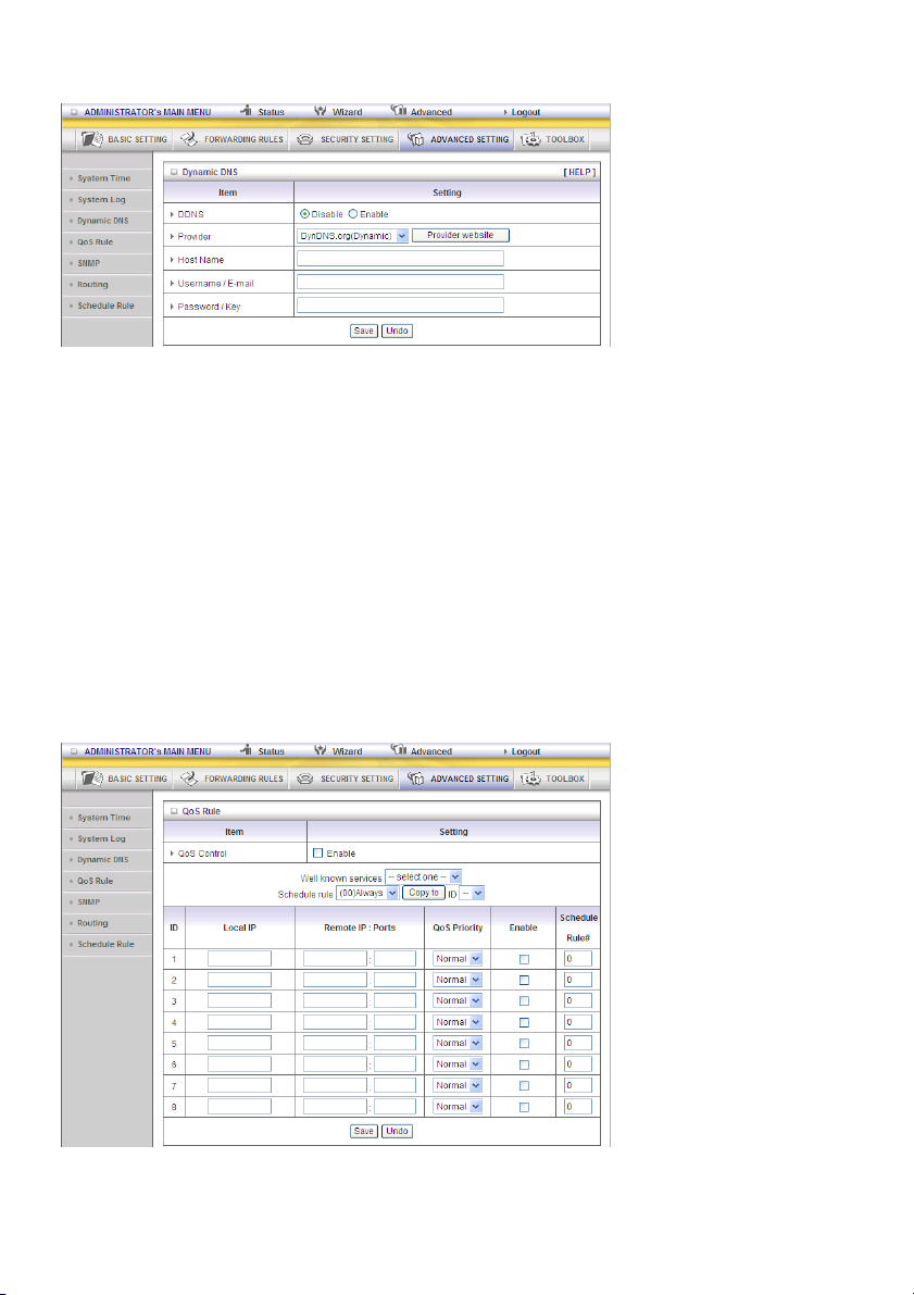
Dynamische DNS
Um Ihren Server auf einer sich änderten IP Adresse zu hosten, müssen Sie den dynamischen Domain
Namen Service (DynDNS) verwenden.
Damit braucht jeder, der Ihren Host erreichen möchte, nur dessen Namen kennen. DynDNS wird den
Namen Ihres Host Ihrer aktuellen IP Adresse zuordnen, die sich jedesmal ändert, wenn Sie sich mit
Ihrem Internet Service Provider verbinden.
Bevor Sie die Dynamic DNS aktivieren, müssen Sie ein Konto auf einem dieser dynamischen DNS
Server registrieren, den wir im Provider Feld aufgelistet haben.
Um die Dynamic DNS zu aktivieren, klicken Sie auf das Kontrollkästchen Enable im Feld DDNS .
Weiter geben Sie die entsprechenden Daten Ihres dynamischen DNS Servers ein.
Sie müssen festlegen:
Provider
Host Name
Benutzername/E-Mail
Passwort/Schlüssel
Sie erhalten diese Information, wenn Sie ein Konto auf einem dynamischen DNS Server registrieren.
QoS
Dieses Gerät unterstützt die QoS Funktion. Die Anwender können eine spezielle Vorschaltung mit
unterschiedlicher Priorität einstellen. Es kann aus drei Prioritäten ausgewählt werden. Die Pakete mit
höherer Priorität werden zuerst verarbeitet.
88
Page 89
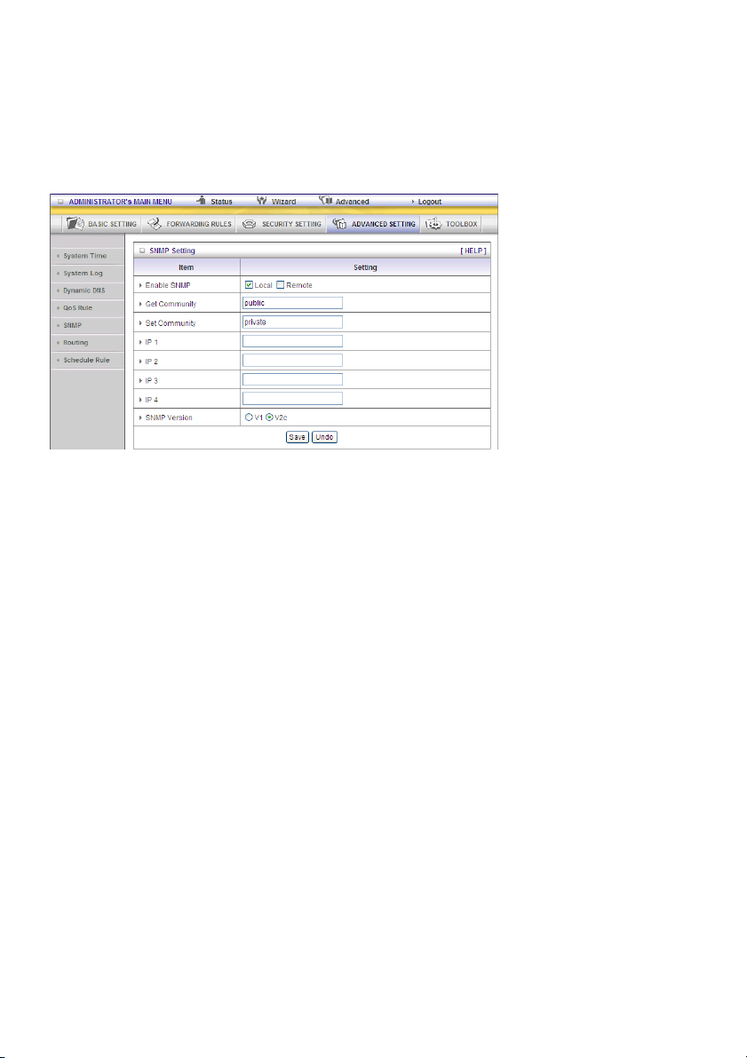
1. QoS: Servicequalität.
2. Local IP/Ports: Die IP und Ports, welche der LAN-seitige PC verwendet. Der Wert 0 bedeutet egal.
3. Remote IP: Ports: Die IP und Ports, welche der Remoteserver einsetzt. Der Wert 0 bedeutet egal.
Wenn Sie z.B. die HTTP Bandbreite garantieren möchten, können Sie die Lokale IP/Port als 0/0,
Remote IP/Port als 0/80 beibehalten.
SNMP
Kurz gesagt, ist das SNMP, das Simple Network Management Protocol, ein Protokoll, das dazu
gedacht ist, einem Anwender die Möglichkeit zu geben, ein Computernetzwerk ferngesteuert zu
verwalten, indem Terminalwerte abgefragt, eingerichtet und Netzwerkereignisse überwacht werden.
Enable SNMP
Sie müssen Lokal; Remote oder beides anhaken, um die SNMP Funktion zu aktivieren. Wenn Lokal
angehakt ist, beantwortet dieses Gerät Anfragen vom LAN. Wenn Remote angehakt ist, beantwortet
dieses Gerät Anfragen vom WAN.
Get Community
Wenn Sie Community einstellen, um Anfragen zu erhalten, reagiert Ihr Gerät darauf.
Set Community
Wenn Sie Community einstellen, um eine Anfrage zu erhalten, akzeptiert Ihr Gerät diese.
IP 1, IP 2, IP 3, IP 4
Geben Sie hier die IP Ihres SNMP Management PCs ein. Der Anwender muss konfigurieren, wohin
dieses Gerät SNMP Trap Nachrichten senden soll.
SNMP Version
Bitte wählen Sie die richtige SNMP Version aus, welche Ihre SNMP Management Software unterstützt.
WAN Access IP Adresse
Wenn der Anwender den Zugriff auf eine bestimmte IP Adresse begrenzen möchte, geben Sie diese
Position bitte ein. Der Standard lautet 0.0.0.0 und bedeutet, dass jede IP aus dem Internet
Informationen von dem Gerät mit SNMP Protokoll erhalten kann.
Klicken Sie auf „Save“, um Ihre Einstellung zu speichern oder auf „Undo“, um den Vorgang
abzubrechen.
89
Page 90

Routing
Routing Table ermöglicht Ihnen festzulegen, welche physikalische Internet Adresse für abgehende IP
Datenmengen verwendet werden. Wenn Sie mehr als einen Router und ein Subnet haben, müssen Sie
die Routing Tabelle aktivieren, damit die Pakete den richtigen Routing Weg finden und verschiedene
Subnets miteinander kommunizieren können.
Die Routing Table Einstellungen sind Einstellungen, die verwendet werden, um die Funktionen des
statischen Routing einzurichten.
Dynamic Routing
Das Routing Informationsprotokoll (RIP) tauscht Informationen über Ziele der Computer durch das
Netzwerk aus. Bitte wählen Sie RIPv2 nur aus, wenn Sie in Ihrem Netzwerk verschiedene Subnets
haben.
Wählen Sie anderenfalls bitte RIPv1 aus, wenn Sie dieses Protokoll benötigen.
Static Routing: Zum statischen Routing können Sie bis zu 8 Routing Regeln festlegen. Sie können die
Ziel-IP Adresse, Subnet Mask, Gateway, Hop für jede Routing Regel eingeben und dann die Regel
aktivieren oder deaktivieren, indem Sie das Kästchen Enable anhaken oder nicht anhaken.
Beispiel:
90
Page 91
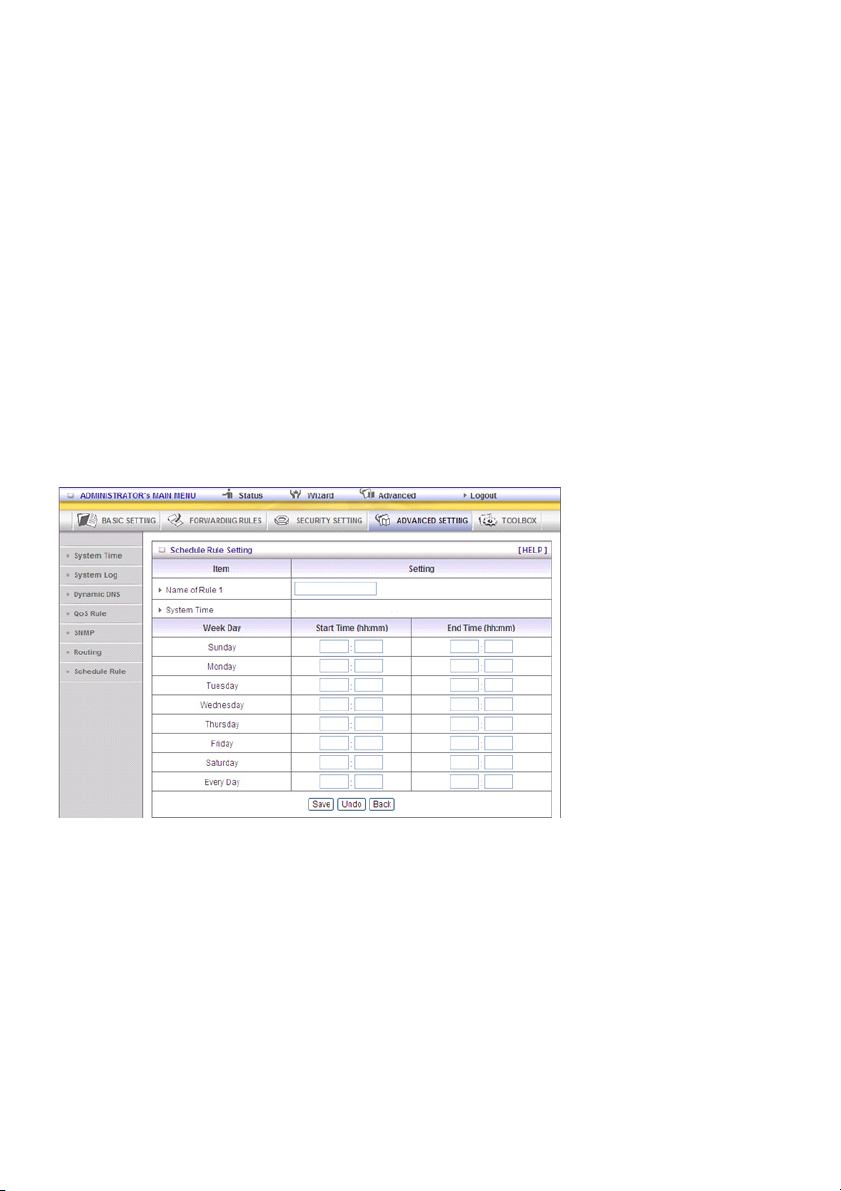
Konfiguration am NAT Router
Destination Subnet Mask Gateway Hop Enabled
192.168.0.1 255.255.255.0 192.168.123.216 1 ˇ
192.168.0.0 255.255.255.0 192.168.123.103 1 ˇ
Wenn also z.B. der Client 3 eine IP Datenmenge an 192.168.0.2 senden möchte, verwendet dieser die
obige Tabelle, um festzulegen, dass dieses über 192.168.123.103 (ein Gateway) gehen muss
und, wenn dieser Pakete an 192.168.1.11 sendet, gehen diese über 192.168.123.216
Jede Regel kann einzeln aktiviert oder deaktiviert werden.
Nachdem die Routing Table Einstellung konfiguriert wurde, klicken Sie auf die Schaltfläche Save.
Schedule Rule
Sie können Zeitplanregeln aufstellen, um zu entscheiden, welcher Dienst ein- oder ausgeschaltet wird.
Wählen Sie das Element „enable“ aus.
Drücken Sie auf „Add New Rule“.
Sie können einen Regelnamen eintragen und einstellen, an welchem Tag und um welche Uhrzeit die
„Start Time“ bis „End Time“ geplant ist. Im folgenden Beispiel wird „ftp time“ jeden Tag 14:10 bis 16:20
konfiguriert
Schedule Enable
Auswählen, wenn Sie den Plan aktivieren möchten.
Edit
Zum Bearbeiten der Zeitplanregeln.
Delete
Um die Zeitregel und die Nummer hinter der gelöschten Regel zu löschen, wird die Nummer
automatisch um eins verringert.
Die Zeitplanregel kann auf den virtuellen Server und dem Paketfilter angewandt werden, z.B.:
Beispiel 1: Virtual Server – Regel Nr. 1 anwenden (ftp Zeit: täglich 14:20 bis 16:30)
91
Page 92

Beispiel 2: Packet Filter – Regel Nr. 1 anwenden (ftp Zeit: täglich 14:20 bis 16:30).
92
Page 93

5.5 TOOLBOX
View Log
Sie können das Systemprotokoll ansehen, indem Sie auf die Schaltfläche View Log klicken
Firmware Upgrade
93
Page 94

Sie können die Firmware aktualisieren, indem Sie auf die Schaltfläche Firmware Upgrade klicken.
5.6 Backup Setting
Sie können Ihre Einstellungen speichern, indem Sie auf die Schaltfläche Backup Setting klicken und
diese als Bin Datei speichern. Sobald Sie diese Einstellungen wieder herstellen möchten, klicken Sie
bitte auf die Schaltfläche Restore Settings und verwenden Sie die von Ihnen gespeicherte Bin Datei.
Auf Standard zurücksetzen
Sie können diesen Router auch auf die Werkseinstellungen zurücksetzen, indem Sie auf die
Schaltfläche „Reset to default“ klicken.
Sie können diesen Router auch neu starten, indem Sie auf die Schaltfläche Reboot klicken.
Verschiedene Elemente
94
Page 95

MAC Adresse für Wake-on-LAN
Wake-on-LAN ist eine Technologie, die es Ihnen ermöglicht, ein vernetztes Gerät ferngesteuert
einzuschalten. Um diese Funktion zu nutzen, muss das Gerät für Wake-on-LAN aktiviert sein und Sie
müssen die MAC Adresse dieses Gerätes kennen, Schreibweise 00-11-22-33-44-55. Klicken Sie auf
die Schaltfläche „Wake up“, damit der Router den Wake-up Rahmen sofort an das Zielgerät sendet.
Domain Name oder IP Adresse für Testzwecke
Hier können Sie eine IP Adresse konfigurieren und das Gerät anpingen. Sie können eine bestimmte IP
Adresse pingen, um zu testen, ob diese aktiv ist.
Sicherheitsvorkehrungen:
Um das Risiko eines elektrischen Schlags zu verringern, sollte
dieses Produkt AUSSCHLIESSLICH von einem autorisierten
Techniker geöffnet werden. Bei Problemen trennen Sie das
Gerät bitte von der Spannungsversorgung und von anderen
Geräten ab. Stellen Sie sicher, dass das Gerät nicht mit
Wasser oder Feuchtigkeit in Berührung kommt.
Wartung:
Nur mit einem trockenen Tuch säubern. Keine Reinigungs- oder Scheuermittel verwenden.
Garantie:
Es kann keine Garantie oder Haftung für irgendwelche Änderungen oder Modifikationen des Produkts
oder für Schäden übernommen werden, die aufgrund einer nicht ordnungsgemäßen Anwendung des
Produkts entstanden sind.
Allgemeines:
- Design und technische Daten können ohne vorherige Ankündigung geändert werden.
- Alle Logos, Marken und Produktnamen sind Marken oder eingetragene Marken ihrer jeweiligen
Eigentümer und werden hiermit als solche anerkannt.
- Diese Bedienungsanleitung wurde sorgfältig verfasst. Dennoch können daraus keine Rechte und
Pflichten hergeleitet werden. König Electronic haftet nicht für mögliche Fehler in dieser
Bedienungsanleitung oder deren Folgen.
- Bitte bewahren Sie Bedienungsanleitung und Verpackung für spätere Verwendung auf.
Achtung:
Dieses Produkt ist mit diesem Symbol gekennzeichnet. Es bedeutet, dass die ausgedienten
elektrischen und elektronischen Produkte nicht mit dem allgemeinen Haushaltsmüll entsorgt
werden dürfen. Für diese Produkte stehen gesonderte Sammelsysteme zur Verfügung.
95
Page 96
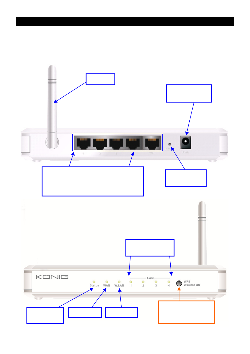
FRANÇAIS
Routeur sans fil
1) CONFIGURATION HARDWARE
CMP-WNROUT50
Antenne
Prise
d'alimentation
lumineux d'état
Ports RJ-45 Auto MDI/MDIX
Détecte automatiquement les types de
réseau WAN et LAN lors de la connexion
par Ethernet
Voyant
Voyant WAN Voyant Wi-Fi
Bouton de
réinitialisation
Voyants lumineux
LAN1~LAN4
Bouton 2 en 1
1. WPS
2. Réseau sans fil activé
96
Page 97

INDICATEURS LUMINEUX
Voyant statut Description
État Vert clignotant Le dispositif est opérationnel
Voyant WAN
Voyant LAN
Voyant Wi-Fi
Vert Le câble RJ45 est branché
Vert clignotant Échange de données
Vert Le câble RJ45 est branché
Vert clignotant Échange de données
Vert Le Wi-Fi est activé
Vert clignotant Échange de données
Vert clignotant rapidement Le dispositif est en mode WPS PBC
Vert foncé Le Wi-Fi est désactivé
FONCTIONS DES BOUTONS
Description
1. Si le signal du réseau sans fil est désactivé, appuyez sur ce bouton pendant
WPS
Réinitialisation Appuyez pendant 6 secondes pour revenir aux paramètres par défaut
1 seconde environ pour activer le signal « radio sans fil ».
2. Si le signal du réseau sans fil est activé, appuyez sur ce bouton pendant 1
seconde environ pour exécuter la fonction WPS.
97
Page 98
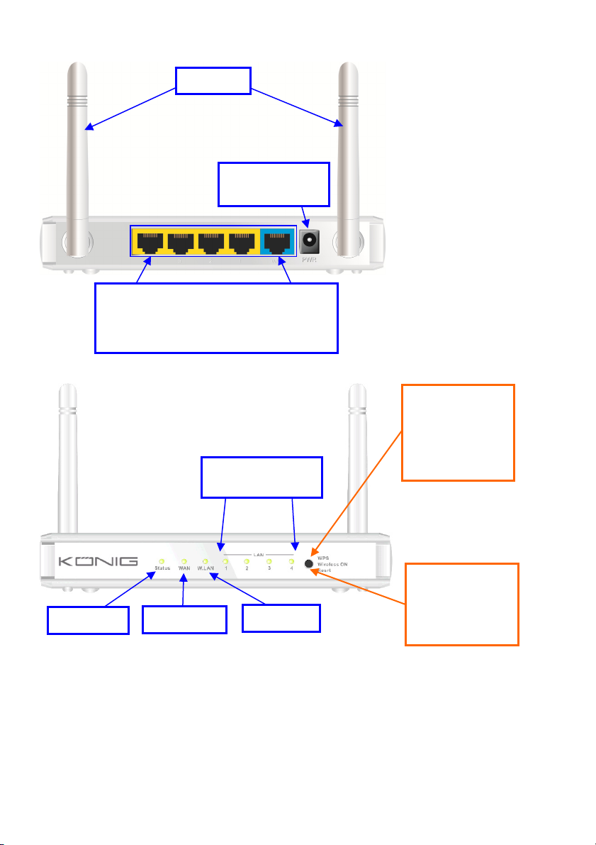
CMP-WNROUT55 et CMP-WNROUT60
Antenne
Prise
d'alimentation
Ports RJ-45 Auto MDI/MDIX
Détecte automatiquement les types de
réseau WAN et LAN lors de la connexion
par Ethernet
CMP-WNROUT55
Bouton 3 en 1
1. WPS
2. Réseau sans fil
activé
Voyants lumineux
3. Réinitialisation
LAN1~LAN4
CMP-WNROUT60
Bouton 2 en 1
1. WPS
Voyant
Voyant WAN
Voyant Wi-Fi
2. Réseau sans fil
activé
98
Page 99

INDICATEURS LUMINEUX
Voyant statut Description
État Vert clignotant Le dispositif est opérationnel
Voyant WAN
Voyant LAN
Voyant Wi-Fi
Vert Le câble RJ45 est branché
Vert clignotant Échange de données
Vert Le câble RJ45 est branché
Vert clignotant Échange de données
Vert Le Wi-Fi est activé
Vert clignotant Échange de données
Vert clignotant rapidement Le dispositif est en mode WPS PBC
Vert foncé Le Wi-Fi est désactivé
FONCTIONS DES BOUTONS
Description
CMP-WNROUT55
Si le signal du réseau sans fil est activé, appuyez sur ce bouton pendant 1
seconde environ pour exécuter la fonction WPS
WPS
Réseau sans fil
activé sur
CMP-WNROUT55
uniquement
Réinitialisation
CMP-WNROUT60
1. Si le signal du réseau sans fil est désactivé, appuyez sur ce bouton pendant 1
seconde environ pour activer le signal « radio sans fil »
2. Si le signal du réseau sans fil est activé, appuyez sur ce bouton pendant 1
seconde environ pour exécuter la fonction WPS
Si le signal du réseau sans fil est désactivé, appuyez sur ce bouton pendant 1
seconde environ pour activer le signal « radio sans fil »
CMP-WNROUT55
1. Appuyez sur ce bouton pour allumer le dispositif
2. Appuyez pendant 3 à 4 secondes environ, le dispositif est réinitialisé avec les
paramètres par défaut. Le voyant de statut clignote ensuite chaque seconde
en mode normal
Remarque : Si le voyant de statut clignote très rapidement, cela indique que ce
bouton a été appuyé trop longuement et que vous devez essayer à nouveau
CMP-WNROUT60
Appuyez pendant 6 secondes pour revenir aux paramètres par défaut, ensuite
relâchez le bouton lorsque le dispositif fonctionne en simultané
99
Page 100

2) INSTALLATION
Étape 1. Insérez le câble Ethernet dans le port
LAN :
Insérez le câble de raccordement Ethernet dans
le port LAN sur le panneau arrière du routeur et à
un port Ethernet libre de la carte réseau de
l'ordinateur que vous souhaitez utiliser pour
configurer l'unité.
Étape 2. Insérez le câble de raccordement
Ethernet à un port WAN câblé :
Insérez le câble de raccordement Ethernet du
modem ADSL au port WAN câblé sur le panneau
arrière du routeur.
Étape 3. Allumez le routeur :
Branchez l'adaptateur d'alimentation à la prise du
panneau arrière de votre routeur.
Étape 4. Complétez l'installation.
100
 Loading...