

Page 1
101
BEZDRÁTOVÝ AUDIOVIZUÁLNÍ
SYSTÉM S TV TUNEREM
79
LANGATON AV-JÄRJESTELMÄ
VIRITTIMELLÄ
57
SISTEMA AV INALÁMBRICO CON
SINTONIZADOR
35
DRAADLOOS AUDIO/
VIDEOSYSTEEM MET TUNER
13
DRAHTLOSES AV-SYSTEM MIT
TUNER
112
SISTEM AV WIRELESS CU TUNER
90
TRÅDLÖST AV-SYSTEM MED
MOTTAGARE
68
VEZETÉK NÉLKÜLI AV RENDSZER
TUNERRAL
46
IMPIANTO AV CON
SINTONIZZATORE
24
SYSTÈME AV SANS FIL AVEC
TUNER
WIRELESS AV SYSTEM WITH
TUNER
VID-TRANS75KN (2.4GHz)
VID-TRANS575KN (5.8GHz)
Page 2
2
ENGLISH
Introduction:
Wireless receiver and transmitter with built-in TV tuner. Due to the tuner it‘s possible
to watch a different TV station on another TV set. Tuner settings for personally desired
program sequence. Extra input for DVD player, Set Top Box or other audio/video source.
These devices can be controlled with original remote control due to IR extension
function.
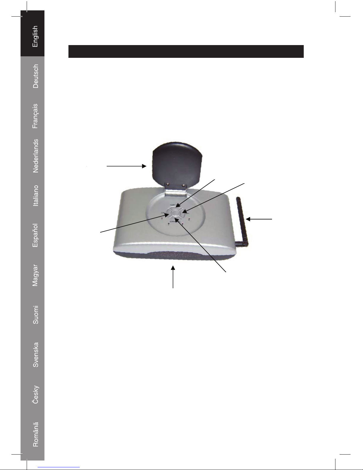
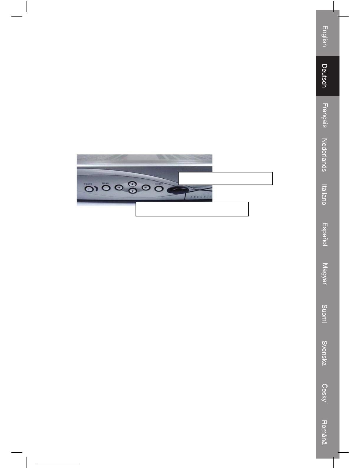
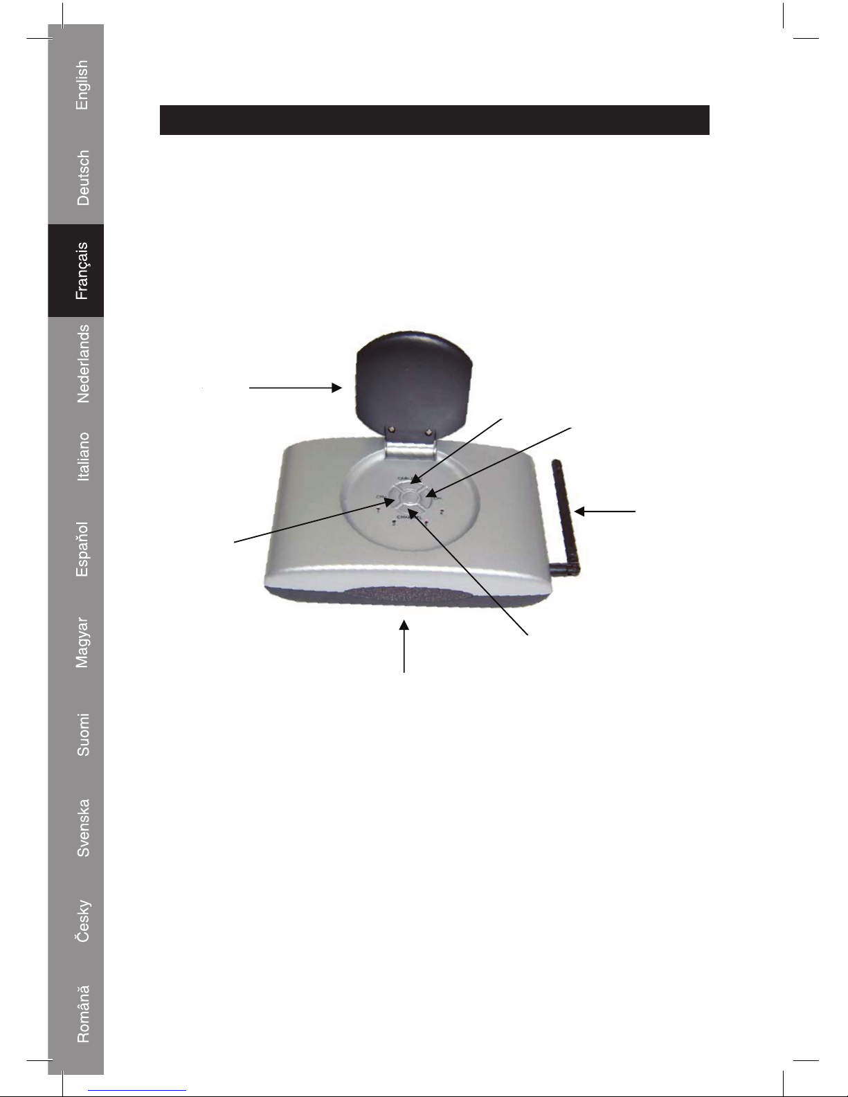
Description front view transmitter and receiver:
1.
2.
3.
4.
5.
6.
7.
1. Directional antenna for transmitting and receiving audio/video signals
2. TV/AV button for selection of built-in tuner (TV) or connected audio/video source (AV)
3. CH- button to select programs downwards
4. Antenna for transmitting and receiving the radio frequency signal of the remote control.
5. Channel button for selection of transmitting and receiving channel. Note: transmitter and
receiver needs to be set to same channel (1,2, 3 or 4)
6. Infrared eye (behind display) for receiving the signal of the remote control
7. CH+ button to select TV programs upwards
Page 3
3
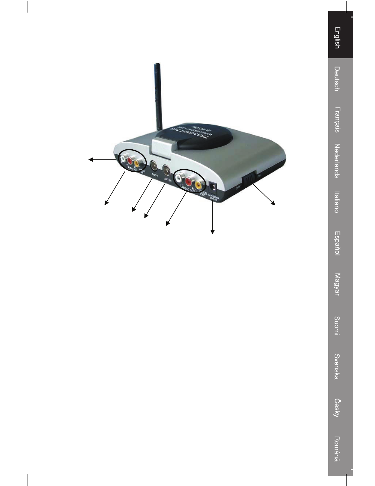
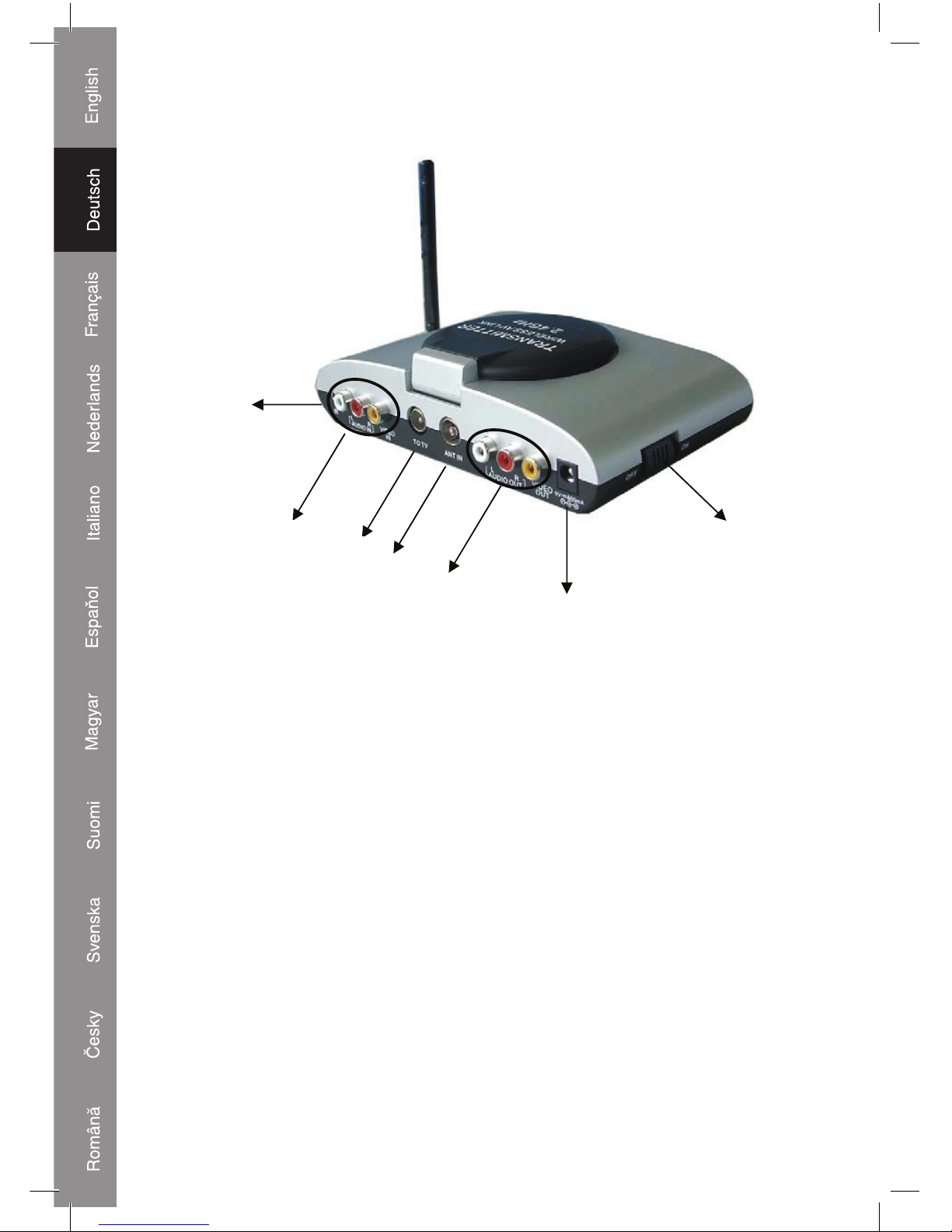
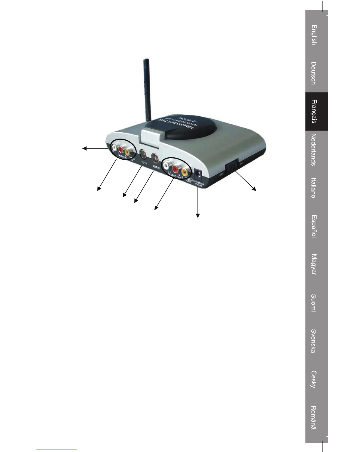
Description rear view transmitter:
1.
3.
2.
4.
6.
7.
5.
1. Input IR extension cable
2. Input for audio/video source. WHITE is audio left, RED is audio right, YELLOW is video
3. Antenna output
4. Antenna input
5. Output for audio/video source to TV or monitor. WHITE is audio left, RED is audio right,
YELLOW is video
6. DC input for supplied AC/DC adapter. Note: use only the supplied 9V/600mA AC/DC
adapter. Use of other AC/DC adapters may damage the transmitter
7. ON/OFF switch
(numbers refer also to chapter: connection of transmitter)
Page 4
4
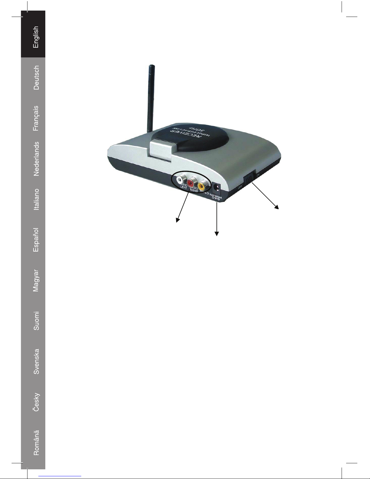
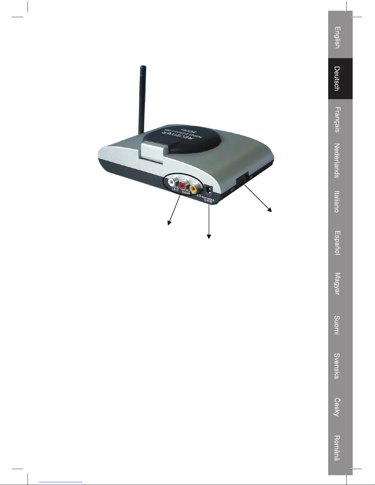
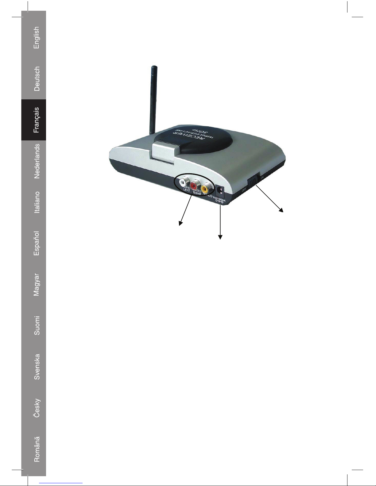
Description rear view receiver:
1.
2.
3.
1. Output to TV or monitor. WHITE is audio left, RED is audio right, YELLOW is video
2. DC input for supplied AC/DC adapter. Note: use only the supplied 9V/400mA AC/DC
adapter. Use of other AC/DC adapters may damage the receiver
3. ON/OFF switch
(numbers refer also to chapter: connection of receiver)
Page 5
5
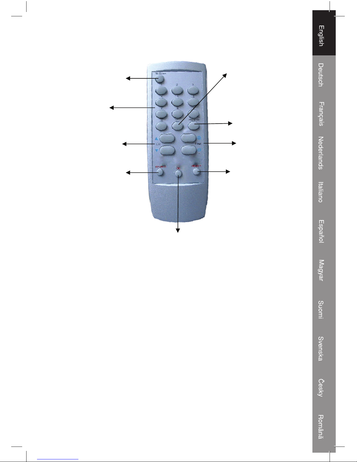
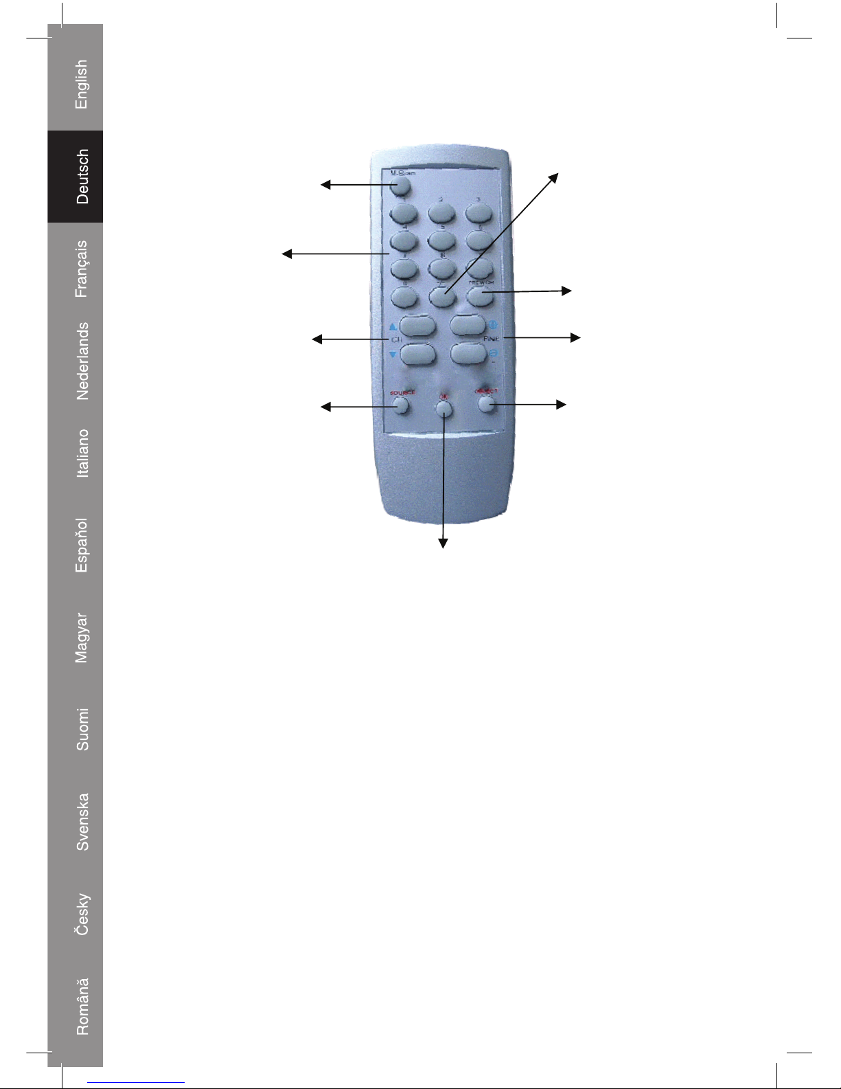
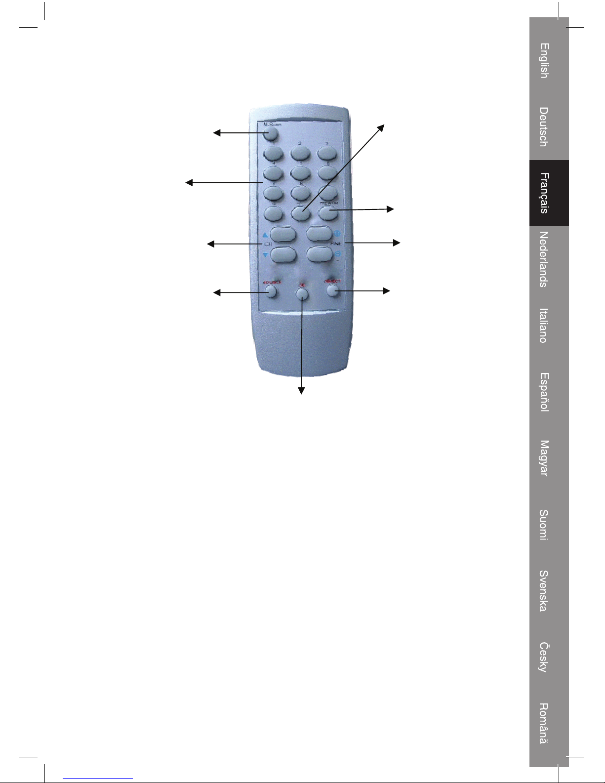
Description remote control:
3.
1.
2.
4.
5.
6.
8.
7.
9.
1. MENU button
2. Numeric buttons
3. CH up button, CH down button (TV program)
4. DEL button
5. OK button
6. -/-- button. -- for channel 10 and above channels. - for channels below 10
7. PREV. CH button for returning to previous selected program
8. FINE (tuning) buttons for adjusting the frequency of the channel.
9. TV/AV button for selection of built-in tuner (TV) or connected audio/video source (AV)
Page 6
6
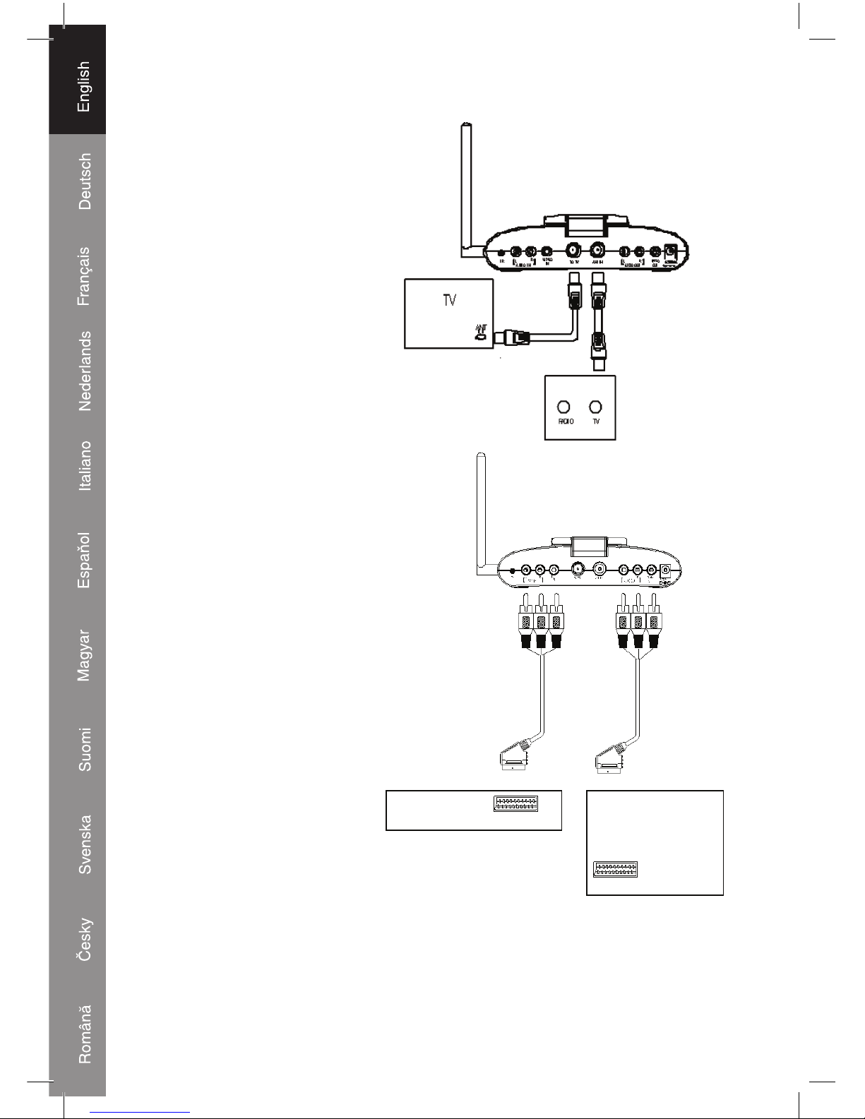
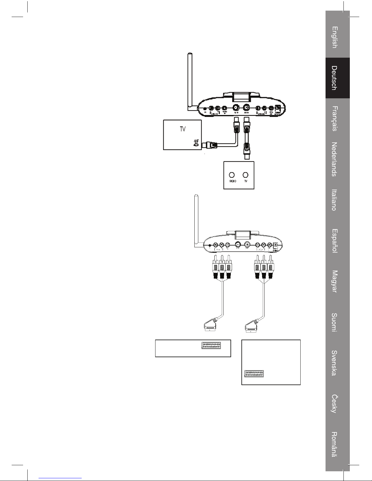
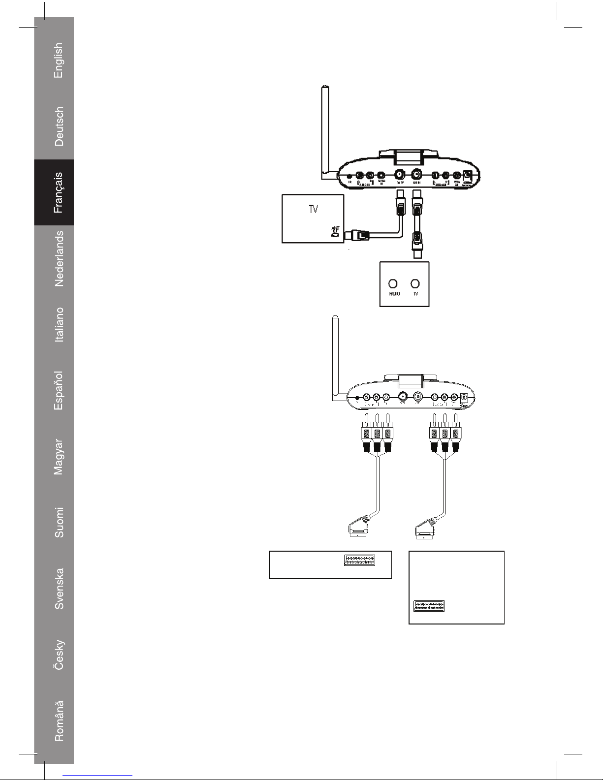
Connection of transmitter:
Trans mit ter:
1) Connect the antenna cable to
the ANT IN (4) input and the
antenna output socket on the
wall.
2) Connect the (existing) antenna
cable to the TO TV (3) output
and the antenna input of TV,
Set Top Box or other source.
3) If a DVD or other source is
directly connected to the
TV, it‘s possible to use the
transmitter for a loop through
of the signal and it offers at the
same time the possibility to
send the signal of the DVD or
other source to the receiver.
Connect the RCA plugs to the
AUDIO/VIDEO IN input (2) and
the Scart plug to the output of the
DVD or other source. Connect the
(existing) audio/video cable to the
AUDIO/VIDEO OUT output (5)
and the AUDIO/VIDEO input on
the TV.
4) Connect the DC plug of the
AC/DC adapter to the 9 V input
(6). Connect the AC plug to a
230 V power outlet.
5) Switch on the transmitter with
the ON/OFF switch (7).
6) Select a channel (1, 2, 3 or
4) with the channel button.
If a channel shows some
distortion, try another channel.
The transmitter and receiver
needs to be set to the same
channel.
Note: if the transmitter is switched OFF and switched ON again the transmitter returns
automatically to channel 1.
DVD
TV
Page 7
7
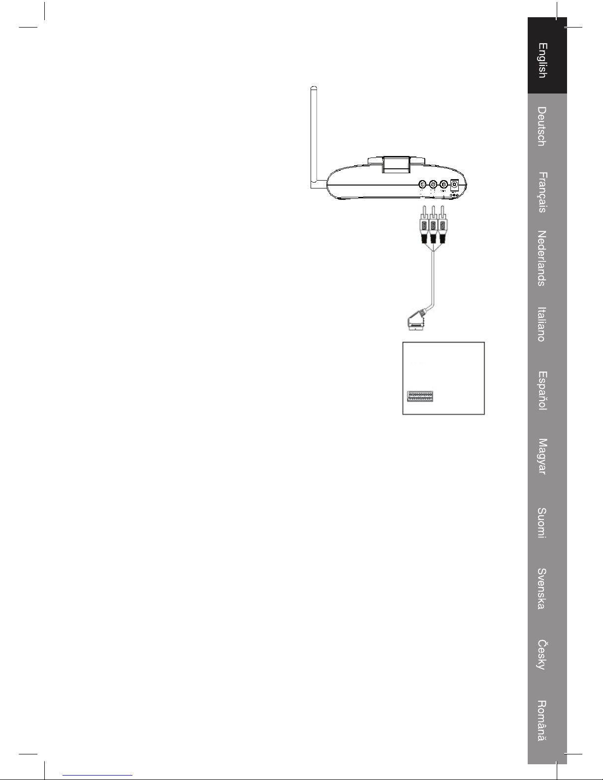
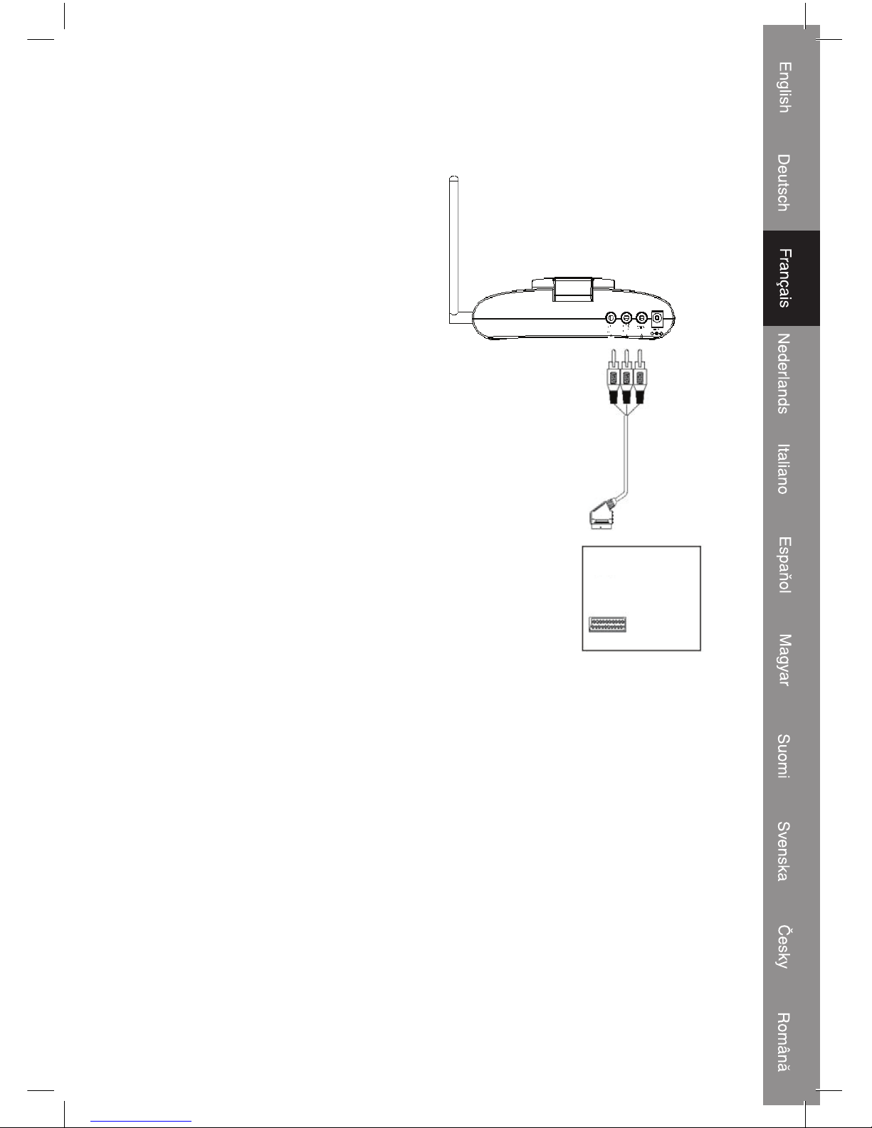
Receiver:
1) Connect the RCA plugs to the AUDIO/
VIDEO OUT output (1) and the Scart plug
to the input of the TV.
2) Connect the DC plug of the AC/DC adapter
to the 9 V input (2). Connect the AC plug
to a 230 V power outlet.
3) Switch on the receiver with the ON/OFF
switch (3).
4) Select a channel (1,2, 3 or 4) with the
channel button. If a channel shows some
distortion, try another channel. The
transmitter and receiver needs to be set to
the same channel.
Note: if the transmitter is switched OFF and
switched ON again the transmitter returns
automatically to channel 1.
For optimum performance, it can be necessary to point the transmitter and receiver to
each other in an imaginary straight line. Or, in case of distortion, replace the transmitter
and/or receiver a bit, a few centimeters could already be enough to improve the sound
and picture quality. Adjustments are not necessary if the reception is perfect.
TV
Page 8
8
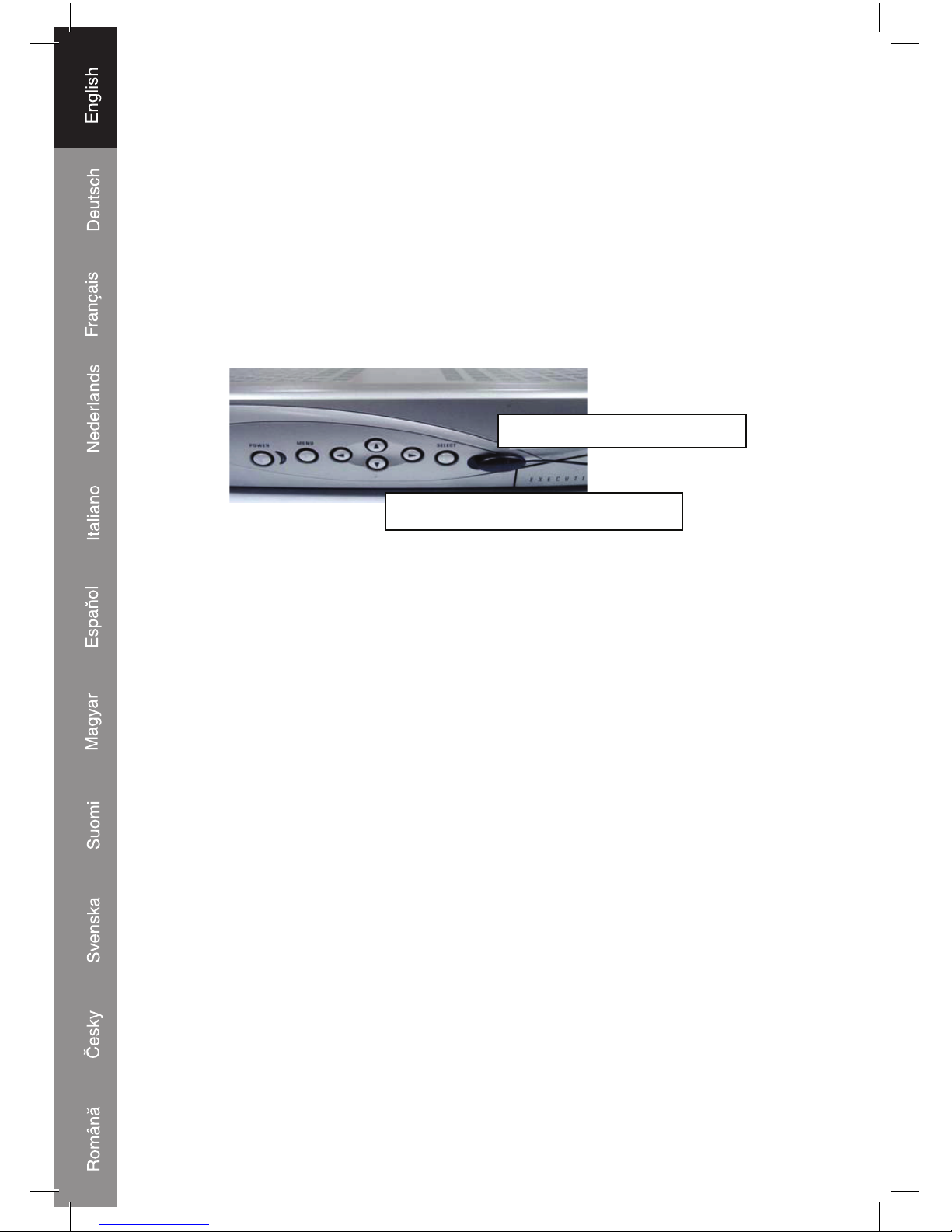
Using the remote control feature:
The system not only offers to send audio/video from one area to another, it also offers the
possibility to control a connected source by using the existing remote control of the source.
It converts the infrared (IR) signal emitted by the remote control to a radio frequency (RF)
signal in the UHF band at the receiver and sends it back to the transmitter where the RF
signal is converted back to the original IR signal and beamed to the source.
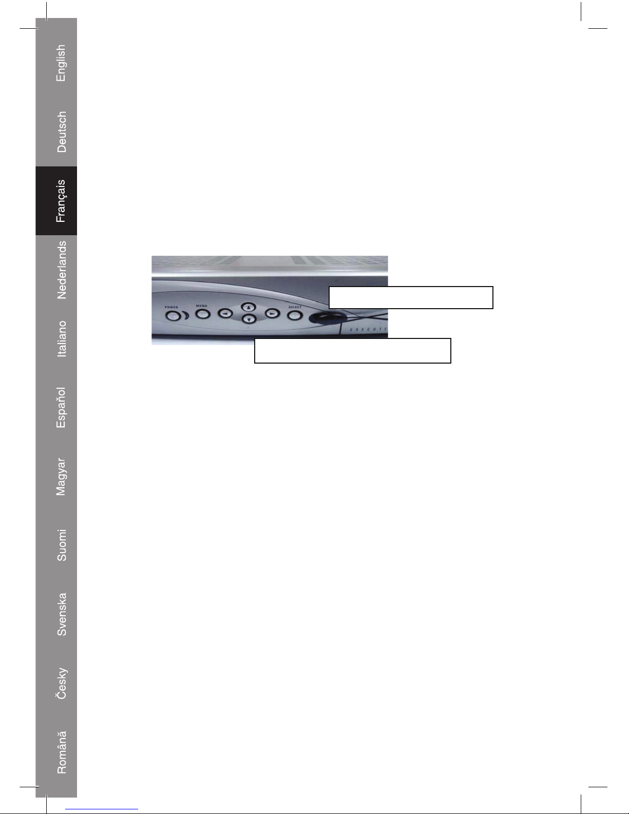
Use the IR cable and connect the 2.5mm plug to the input jack on the back of the
transmitter (IR). Place the IR sensor in front of the display of the source that needs to
be controlled. It’s important to place the IR sensor as close as possible to the IR sensor,
which is behind the display, of the source.
Set up:
Before starting the set up, be sure that all connections are made and the system is
switched on.
Push the MENU button (1) on the remote control to enter the menu.
The menu offers the following options;
AUTOMATIC PROGRAMMING
MANUAL DOWN SEARCHING
MANUAL UP SEARCHING
SORTING PROGRAMS
Use the CH buttons (3) on the remote control to select an option. Push the OK button (5)
to confi rm.
AUTOMATIC PROGRAMMING
Select this option for automatic programming of all available channels (programs). The
found channels will be stored in random order. During programming the TV channels, the
display shows: CHANNEL SCANNING, PLEASE WAIT. When the scanning is fi nalized
the TV shows the fi rst channel (CH00). Push the CH buttons (3) to select a channel.
Note: automatic programming is recommended
MANUAL DOWN/UP SEARCHING
Select DOWN (downwards searching in the frequency band) or UP (upwards searching
in the frequency band) for manual programming of each channel. Push the OK button (5)
to confi rm.
VCR, DVD, SAT or other device
IR sensor in front of display
Page 9

9
SORTING PROGRAMS
This option offers the possibility to set channels in a desired sequence.
1) Select a channel to be set to another channel number (e.g. channel 4 needs to be
channel 1)
2) Press MENU, select SORTING PROGRAMS and push the OK button
3) The TV shows: INPUT OBJECT, PRESS OK EXC. Insert the new channel number and
push OK.
4) The channels in fact are switched. Repeat above steps to set all channels in a desired
sequence.
Page 10
10
Specifi cations:
Transmitter:
Operating frequency band
- VID-TRANS75KN 2.400 GHz~2.4835 GHz
- VID-TRANS575KN 5.725 GHz~5.875 GHz
Output level 90 dBμV/m at 3 meters
Modulation FM (video and audio)
Channel (4CH) PLL frequency synthesizer
Video input level 1 V p-p/75 Ohm
Audio input level 1 V p-p/600 Ohm (STEREO)
Input port RCA
Output port RCA
Antenna Directional fl at antenna
IR–remote IR output 940nm with ON/OFF keying
Infrared emission carrier 38 KHz
Built in TV tuner VHF low, VHF high, UHF
Standard PAL B/G
Memory 100 Channels
Power consumption 9 V DC, 600mA
Dimension 18×12×5 cm
Weight 500 g
Receiver:
Operating frequency band
- VID-TRANS75KN 2.400 GHz~2.4835 GHz
- VID-TRANS575KN 5.725 GHz~5.875 GHz
Channel (4CH) PLL frequency synthesizer
Video output level 1 V p-p/75 Ohm
Audio output level 1 V p-p/600 Ohm (STEREO)
Output port RCA
Antenna Directional fl at antenna
IR-transmit frequency 433.92 MHz
Infrared frequency input 35 KHz~41 KHz
Power consumption 9 V DC, 400 mA
Dimension 18×12×5 cm
Weight 410 g
System:
Operational range: up to 100 meter (open fi eld), indoor max. 30 meter.
Remote control range: up to 50 meter (open fi eld), indoor max. 30 meter.
Actual range depends on environmental circumstances.
Page 11
11
Safety precautions:
RISK OF E LECTRIC SHOCK
DO NOT OPE N
CAUTION
To reduce risk of electric shock, this product should
ONLY be opened by an authorized technician when
service is required. Disconnect the product from mains
and other equipment if a problem should occur. Do not expose the product to water or
moisture.
Maintenance:
Clean only with a dry cloth. Do not use cleaning solvents or abrasives.
Warranty:
No guarantee or liability can be accepted for any changes and modifi cations of the
product or damage caused due to incorrect use of this product.
General:
Designs and specifi cations are subject to change without notice.
All logos brands and product names are trademarks or registered trademarks of their
respective holders and are hereby recognized as such.
Attention:
This product is marked with this symbol. It means that used electrical and
electronic products should not be mixed with general household waste. There
is a separate collections system for these products.
Page 12
12
Declaration of conformity
We,
Nedis B.V.
De Tweeling 28
5215MC ’s-Hertogenbosch
The Netherlands
Tel.: 0031 73 599 1055
Email: info@nedis.com
Declare that product:
Name: König Electronic
Model: VID-TRANS75, 575
Description: Wireless audio/video transmission system
Is in conformity with the following standards
EN 300 440-2:2001, EN 300 440-2 V1.1.2 (2004-07),
EN 300 220-1/-3:2000, EN 300 220-2 V2.1.1 (2006-04),
EN 301 489-1/-3:2000, EN 301 489-1 V1.6.1 (2005-09),
EN 301 489-3 V1.4.1 (2002-08), EN 60065:1998,
EN 60065:2002; IEC 60065:2001
And complies with the requirements of the European Union Directives 1999/5/EC.
‘s-Hertogenbosch, 26-08-2008
Mrs. J. Gilad
Purchase Director
Copyright ©
Page 13
13
DEUTSCH
Einführung:
Drahtloser Receiver und Transmitter mit eingebautem TV-Tuner. Der Tuner macht es
möglich, dass Sie auf einem weiteren Bildschirm einen anderen Fernsehsender sehen.
Tunereinstellungen für persönlich gewünschte Programmfolge. Zusätzlicher Eingang
für DVD-Player, Set Top Box oder andere Audio/Video-Quellen. Wegen der InfrarotVerlängerungsfunktion können diese Geräte mit der ursprünglichen Fernbedienung
bedient werden.
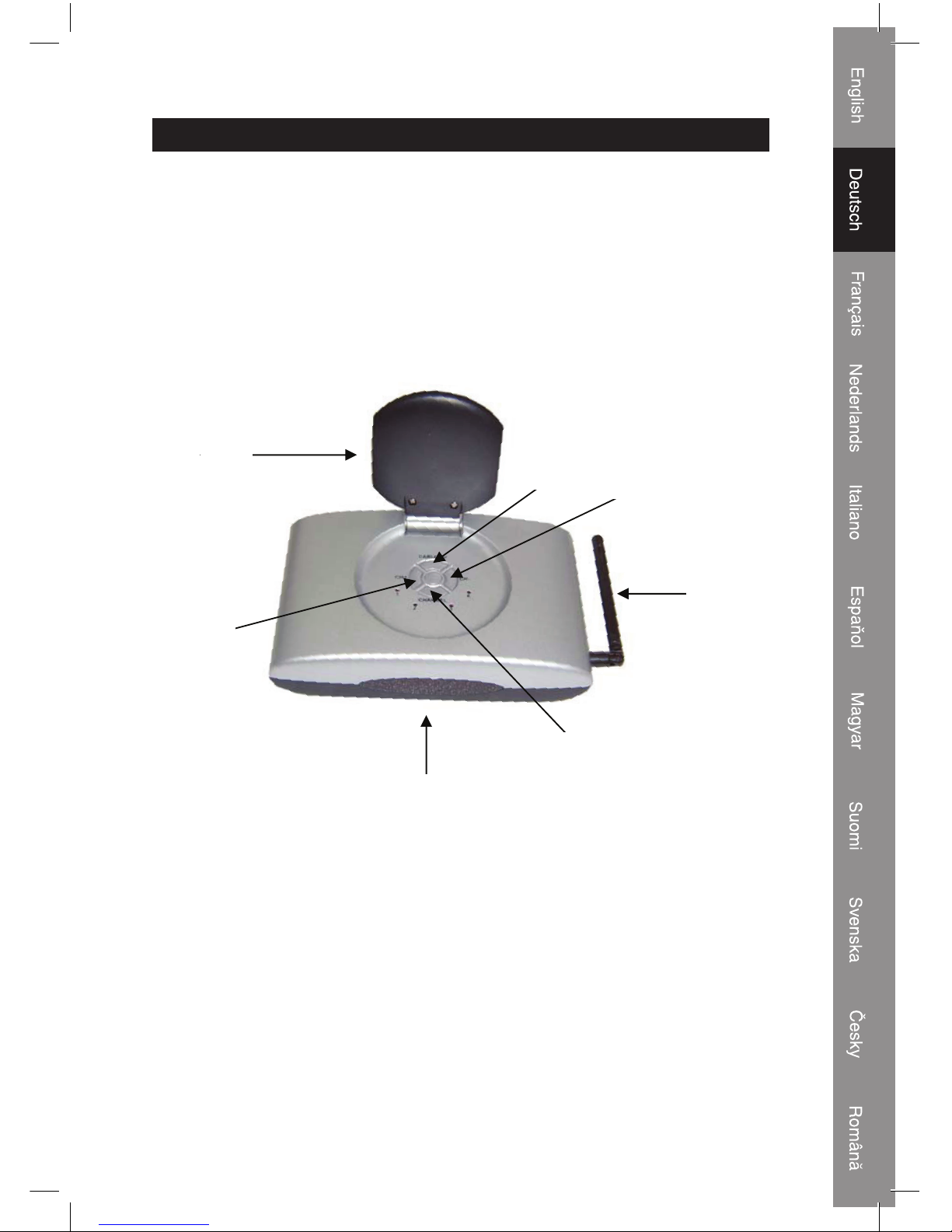
Beschreibung der Vorderansicht von Transmitter und Receiver:
1.
2.
3.
4.
5.
6.
7.
1. Richtantenne zum Senden und Empfangen von Audio/Video-Signalen
2. TV/AV-Taste zur Auswahl des eingebauten Tuners (TV) oder zum Anschluss der Audio/
Video-Quelle (AV)
3. "CH-"-Taste, um Fernsehprogramme abwärts auszuwählen
4. Antenne zum Senden und Empfangen des Hochfrequenzsignals der Fernbedienung
5. Kanal-Taste zur Auswahl des Sende- und Empfangskanals. Anmerkung: Transmitter
und Receiver müssen auf denselben Kanal eingestellt sein (1, 2, 3 oder 4)
6. Infrarotauge (hinter dem Display) zum Empfang des Signals von der Fernbedienung
7. "CH+"-Taste, um Fernsehprogramme aufwärts auszuwählen
Page 14
14
Beschreibung der Rückansicht des Transmitters:
1.
3.
2.
4.
6.
7.
5.
1. Eingang für IR-Verlängerungskabel
2. Eingang für Audio/Video-Quelle. WEISS ist Audio links, ROT ist Audio rechts, GELB ist
Video
3. Antennenausgang
4. Antenneneingang
5. Ausgang für Audio/Video-Quelle zum Fernseher oder Monitor. WEISS ist Audio links,
ROT ist Audio rechts, GELB ist Video
6. DC-Eingang für mitgelieferten Netzadapter. Anmerkung: Benutzen Sie nur den
mitgelieferten 9 V/600 mA-Netzadapter. Wenn Sie andere Netzadapter benutzen, kann
der Transmitter beschädigt werden.
7. An/Aus-Schalter
(die Nummern gelten auch für das Kapitel "Anschluss des Transmitters")
Page 15
15
Beschreibung der Rückansicht des Receivers:
1.
2.
3.
1. Ausgang zum Fernseher oder Monitor. WEISS ist Audio links, ROT ist Audio rechts,
GELB ist Video
2. DC-Eingang für mitgelieferten Netzadapter. Anmerkung: Benutzen Sie nur den
mitgelieferten 9 V/400 mA-Netzadapter. Wenn Sie andere Netzadapter benutzen, kann
der Receiver beschädigt werden.
3. An/Aus-Schalter
(die Nummern gelten auch für das Kapitel "Anschluss des Receivers")
Page 16
16
Beschreibung der Fernbedienung:
3.
1.
2.
4.
5.
6.
8.
7.
9.
1. MENU-Taste
2. Zifferntasten
3. Kanal-aufwärts-Taste, Kanal-abwärts-Taste (Fernsehprogramm)
4. DEL-Taste
5. OK-Taste
6. -/-- Taste. -- für Kanal 10 und darüber. - für die Kanäle unterhalb von 10.
7. PREV.CH-Taste zur Rückkehr zum vorigen ausgewählten Programm
8. FINE-Tasten zur Einstellung der Kanalfrequenz
9. TV/AV-Taste zur Auswahl des eingebauten Tuners (TV) oder zum Anschluss der Audio/
Video-Quelle (AV)
Page 17
17
Anschluss des Transmitters:
Trans mit ter:
1) Schließen Sie das
Antennenkabel an den ANT
IN-Eingang (4) und die
Antennenausgangsbuchse an
die Wandsteckdose an.
2) Schließen Sie das
(vorhandene) Antennenkabel
an den TO TV-Ausgang (3)
und an den Antenneneingang
des Fernsehers, der Set Top
Box oder einer anderen Quelle
an.
3) Wenn ein DVD-Player
oder eine andere Quelle
direkt an den Fernseher
angeschlossen wird, kann
man den Transmitter für ein
Loop-Through des Signals
benutzen, und gleichzeitig
erhält man die Möglichkeit,
das Signal des DVD-Players
oder einer anderen Quelle
zum Receiver zu senden.
Schließen Sie die Cinch-Stecker
an den AUDIO/VIDEO IN-Eingang
(2) und den Scart-Stecker an
den Ausgang des DVD-Players
oder einer anderen Quelle an.
Schließen Sie das (vorhandene)
Audio/Video-Kabel an den
AUDIO/VIDEO OUT-Ausgang (5)
und den AUDIO/VIDEO-Eingang
des Fernsehers an.
4) Schließen Sie den DC-Stecker
des Netzadapters an den
9 V Eingang (6) an. Schließen
Sie den Netzstecker an eine
230 V Netzsteckdose an.
5) Schalten Sie den Transmitter mit dem An-/Ausschalter (7) an.
DVD
TV
Page 18

18
6) Wählen Sie mit der Kanal-Taste einen Kanal (1, 2, 3 oder 4) aus. Wenn ein Kanal etwas
verzerrt ist, versuchen Sie es mit einem anderen Kanal. Der Transmitter und Receiver
müssen auf denselben Kanal eingestellt sein.
Anmerkung: Wenn der Transmitter ausgeschaltet und wieder angeschaltet wird, kehrt er
automatisch wieder auf Kanal 1 zurück.
Empfänger:
1) Schließen Sie die Cinch-Stecker an den
AUDIO/VIDEO OUT-Ausgang (1) und
den Scart-Stecker an den Eingang des
Fernsehers an.
2) Schließen Sie den DC-Stecker des
Netzadapters an den 9 V-Eingang (2) an.
Schließen Sie den Netzstecker an eine
230 V-Netzsteckdose an.
3) Schalten Sie den Receiver mit dem An-/
Ausschalter (3) an.
4) Wählen Sie mit der Kanal-Taste einen
Kanal (1, 2, 3 oder 4) aus. Wenn ein Kanal
etwas verzerrt ist, versuchen Sie es mit
einem anderen Kanal. Der Transmitter und
Receiver müssen auf denselben Kanal
eingestellt sein.
Anmerkung: Wenn der Transmitter
ausgeschaltet und wieder angeschaltet wird,
kehrt er automatisch wieder auf Kanal 1
zurück.
Um die optimale Leistung zu erhalten, könnte es nötig sein, den Transmitter und Receiver
auf einer gedachten geraden Linie gegenüber zu stellen. Oder verschieben Sie bei einer
Verzerrung den Transmitter und/oder Receiver etwas, ein paar Zentimeter könnten schon
reichen, um die Ton- und Bildqualität zu verbessern. Wenn der Empfang perfekt ist, sind
keine Einstellungen erforderlich.
TV
Page 19
19
Benutzung der Fernbedienung:
Das System ermöglicht nicht nur das Senden von Audio/Video von einem Bereich zu
einem anderen, Sie können mit der vorhandenen Fernbedienung auch die Quelle
bedienen. Es wandelt das von der Fernbedienung ausgestrahlte Infrarotsignal (IR) in ein
Hochfrequenzsignal (HF) im UHF-Band des Empfängers um und sendet es zum Sender
zurück, wo das HF-Signal wieder in das ursprüngliche IR-Signal umgewandet wird und
zur Audio/Video-Quelle gestrahlt wird.
Stecken Sie den 2,5-mm-Stecker des Infrarotkabels in die Eingangsbuchse an der
Rückseite des Transmitters (IR). Bringen Sie den Infrarotsensor an der Vorderseite
des Bildschirms des zu bedienenden Geräts an. Es ist wichtig, dass der Infrarotsensor
möglichst nahe bei dem Infrarotsensor angebracht wird, der sich hinter dem Bildschirm
des Geräts befi ndet.
Einrichtung:
Bevor Sie mit der Einrichtung beginnen, müssen Sie sich davon überzeugen, dass alle
Anschlüsse hergestellt worden sind und das System angeschaltet ist.
Drücken Sie auf die MENU-Taste (1) an der Fernbedienung, um das Menü zu öffnen.
Das Menü bietet folgende Optionen:
AUTOMATIC PROGRAMMING (Automatische Programmierung)
MANUAL DOWN SEARCHING (Manuelle Abwärtssuche)
MANUAL UP SEARCHING (Manuelle Aufwärtssuche)
SORTING PROGRAMS (Sortierprogramme)
Wählen Sie mit den CH-Tasten (3) an der Fernbedienung eine Option aus. Drücken Sie
zur Bestätigung die OK-Taste (5).
AUTOMATIC PROGRAMMING (Automatische Programmierung)
Wählen Sie diese Option zur automatischen Programmierung aller vorhandenen Kanäle
(Programme) aus. Die gefundenen Kanäle werden in willkürlicher Reihenfolge gespeichert.
Während der Programmierung der Kanäle wird angezeigt: CHANNEL SCANNING,
PLEASE WAIT. Wenn die Suche beendet ist, wird auf dem Fernseher der erste Kanal
(CH00) angezeigt. Drücken Sie die CH-Tasten (3), um einen Kanal auszuwählen.
Anmerkung: Es wird automatische Programmierung empfohlen.
VCR, DVD, SAT oder anderes Gerät
Infrarotsensor vor dem Display
Page 20
20
MANUAL DOWN/UP SEARCHING (Manuelle Ab-/Aufwärtssuche)
Wählen Sie DOWN (Abwärtssuche im Frequenzband) oder UP (Aufwärtssuche im
Frequenzband), um alle Kanäle manuell zu programmieren. Drücken Sie zur Bestätigung
die OK-Taste (5).
SORTING PROGRAMS (Sortierprogramme)
Mit dieser Option können Sie Kanäle in Ihrer gewünschten Reihenfolge einstellen.
1) Wählen Sie den auf eine andere Kanalnummer einzustellenden Kanal aus (aus Kanal 4
soll z.B. Kanal 1 werden).
2) Drücken Sie die MENU-Taste, wählen Sie SORTING PROGRAMS aus, und drücken
Sie die OK-Taste.
3) Auf dem Fernseher wird angezeigt: INPUT OBJECT, PRESS OK EXC. Geben Sie die
neue Kanalnummer ein und drücken OK.
4) Die Kanäle werden tatsächlich umgeschaltet. Wiederholen Sie die Schritte von oben,
um alle Kanäle in der gewünschten Reihenfolge einzustellen.
Page 21

21
Technische Daten:
Transmitter:
Frequenzbereich:
- VID-TRANS75KN 2,400 GHz - 2,4835 GHz
- VID-TRANS575KN 5,725 GHz - 5,875 GHz
Ausgangspegel 90 dBμV/m bei 3 Meter
Modulation FM (Video und Audio)
Kanal (4CH) PLL-Frequenzgenerator
Video-Eingangspegel 1 Vss/75 Ohm
Audio-Eingangspegel 1 Vss/600 Ohm (Stereo)
Eingangsanschluss Cinch
Ausgangsanschluss Cinch
Antenne Richtungsfl achantenne
IR–Fernbedienung, IR-Ausgang 940 nm mit An/Aus-Taste
Infrarot-Sendeträgerfrequenz 38 kHz
Eingebauter TV-Tuner VHF niedrig, VHF hoch, UHF
Normal PAL B/G
Speicher 100 Kanäle
Stromverbrauch 9 V DC, 600 mA
Abmessungen 18×12×5 cm
Gewicht 500 g
Empfänger:
Frequenzbereich:
- VID-TRANS75KN 2,400 GHz - 2,4835 GHz
- VID-TRANS575KN 5,725 GHz - 5,875 GHz
Kanal (4CH) PLL-Frequenzgenerator
Video-Ausgangspegel 1 Vss/75 Ohm
Audio-Ausgangspegel 1 Vss/600 Ohm (Stereo)
Ausgangsanschluss Cinch
Antenne Richtungsfl achantenne
IR-Sendefrequenz 433,92 MHz
Infrarot-Frequenzeingang 35 kHz - 41 kHz
Stromverbrauch 9 V DC, 400 mA
Abmessungen 18×12×5 cm
Gewicht 410 g
System:
Betriebsreichweite: Bis zu 100 m (offenes Gebiet), innen max. 30 m.
Fernbedienungsreichweite: Bis zu 50 m (offenes Gebiet), innen max. 30 m.
Die wirkliche Reichweite hängt von den Umgebungsbedingungen ab.
Page 22
22
Sicherheitsvorkehrungen:
STROMSCHLAGGEFAHR
NICHT ÖFFNEN
VORSICHT
Um das Risiko eines elektrischen Schlags zu
verringern, sollte dieses Produkt AUSSCHLIESSLICH
von einem autorisierten Techniker geöffnet werden,
wenn eine Wartung erforderlich ist. Trennen Sie das Produkt vom Stromnetz und anderen
Geräten, wenn ein Problem auftreten sollte. Sorgen Sie dafür, dass das Gerät nicht mit
Wasser oder Feuchtigkeit in Berührung kommt.
Wartung:
Nur mit einem trockenen Tuch säubern. Keine Reinigungs- oder Scheuermittel
verwenden.
Garantie:
Es kann keine Garantie oder Haftung übernommen werden, wenn am Produkt Änderungen
oder Modifi kationen vorgenommen wurden, oder aufgrund einer nicht ordnungsgemäßen
Anwendung des Produktes Schäden entstanden sind.
Allgemeines:
Konstruktionen und technische Daten können ohne vorherige Ankündigung geändert
werden.
Alle Logos, Marken und Produktnamen sind Warenzeichen oder registrierte Warenzeichen
ihrer jeweiligen Eigentümer und werden hiermit als solche anerkannt.
Achtung:
Dieses Produkt ist mit diesem Symbol gekennzeichnet. Es bedeutet, dass die
verwendeten elektrischen und elektronischen Produkte nicht im allgemeinen
Haushaltsmüll entsorgt werden dürfen. Für diese Produkte stehen gesonderte
Sammelsysteme zur Verfügung.
Page 23
23
KONFORMITÄTSERKLÄRUNG
Wir,
Nedis B.V.
De Tweeling 28
5215MC ’s-Hertogenbosch
Niederlande
Tel.: 0031 73 599 1055
Email: info@nedis.com
erklären, dass das Produkt:
Name: König Electronic
Modell: VID-TRANS75 / VID-TRANS575
Beschreibung: Drahtloses Audio/Video-Sendesystem
die Bestimmungen der folgenden EG-Richtlinien erfüllt:
Angewendete Normen:
EN 300 440-2:2001, EN 300 440-2 V1.1.2 (2004-07),
EN 300 220-1/-3:2000, EN 300 220-2 V2.1.1 (2006-04),
EN 301 489-1/-3:2000, EN 301 489-1 V1.6.1 (2005-09),
EN 301 489-3 V1.4.1 (2002-08), EN 60065:1998,
EN 60065:2002; IEC 60065:2001
‘s-Hertogenbosch, 26.08.2008
J. Gilad
Einkaufsleiterin
Copyright ©
Page 24
24
FRANCAIS
Introduction :
Emetteur/récepteur sans fi l avec tuner TV intégré. Grâce au tuner il est possible de
regarder une chaîne de télévision différente sur un autre téléviseur. Paramétrage de tuner
possible pour personnaliser l'ordre des chaînes. Entrée supplémentaire pour lecteur
DVD, Set Top Box ou une autre source audio/vidéo. Ces périphériques peuvent être
commandés avec la télécommande d'origine grâce à la fonction d'extension IR.
Descriptif de la vue avant de l'émetteur/récepteur :
1.
2.
3.
4.
5.
6.
7.
1. Antenne directionnelle pour l'émission et la réception des signaux audio/vidéo
2. Touche TV/AV pour la sélection du tuner TV intégré ou d'une source audio/vidéo (AV)
raccordée
3. Touche CH- pour la sélection de chaîne de façon descendante
4. Antenne pour l'émission et la réception du signal de fréquence radio de la
télécommande.
5. Touche canal pour la sélection du canal d'émission et de réception. Remarque :
l'émetteur et le récepteur doivent être paramétrés sur le même canal (1,2, 3 ou 4)
6. Oeil infrarouge (derrière le panneau d'affi chage) pour la réception du signal de la
télécommande
7. Touche CH+ pour la sélection de chaîne de façon ascendante
Page 25
25
Descriptif de la vue arrière de l'émetteur :
1.
3.
2.
4.
6.
7.
5.
1. Câble d'extension pour l'entrée IR
2. Entrée pour une source audio/vidéo. BLANC = audio gauche, ROUGE = audio droite,
JAUNE = vidéo
3. Sortie antenne
4. Entrée antenne
5. Sortie pour une source Audio/Vidéo vers un téléviseur ou un écran. BLANC = audio
gauche, ROUGE = audio droite, JAUNE = vidéo
6. Entrée CC pour l'adaptateur secteur fourni. Remarque : N'utilisez que l'adaptateur
secteur 9V/600mA fourni. L'utilisation d'un autre adaptateur secteur pourrait
endommager l'émetteur
7. Interrupteur MARCHE/ARRET
(les numéros font également référence au chapitre : raccordement de l'émetteur)
Page 26
26
Descriptif de la vue arrière du récepteur :
1.
2.
3.
1. Sortie pour téléviseur ou écran. BLANC = audio gauche, ROUGE = audio droite, JAUNE
= vidéo
2. Entrée CC pour l'adaptateur secteur fourni. Remarque : N'utilisez que l'adaptateur
secteur 9V/400mA fourni. L'utilisation d'un autre adaptateur secteur pourrait
endommager le récepteur
3. Interrupteur MARCHE/ARRET
(les numéros font également référence au chapitre : raccordement du récepteur)
Page 27
27
Descriptif de la télécommande :
3.
1.
2.
4.
5.
6.
8.
7.
9.
1. Touche MENU
2. Pavé numérique
3. Touche CH +, Touche CH - (chaînes TV)
4. Touche DEL (Effacer)
5. Touche OK
6. Touche -/-- . -- pour la chaîne 10 et les chaînes d'après. - pour les chaînes en dessous
de 10
7. PREV. (PRECEDENT) Touche CH pour revenir à la chaîne précédente
8. Touche FINE (Réglage de précision) pour régler la fréquence de la chaîne.
9. Touche TV/AV pour la sélection du tuner TV intégré ou d'une source audio/vidéo (AV)
raccordée
Page 28
28
Raccordement de l'émetteur :
Émetteur :
1) Raccordez le câble d'antenne
à l'entrée ANT IN (4) et la prise
de sortie de l'antenne à la prise
d'antenne murale.
2) Raccordez le câble d'antenne
(existant) à la sortie TO TV
(3) et à l'entrée antenne du
téléviseur, de la Set Top Box
ou de toute autre source.
3) Si un lecteur DVD ou toute
autre source est directement
raccordé au téléviseur, il est
possible d'utiliser l'émetteur
pour mettre le signal en
boucle, ce qui permet en
même temps d'envoyer le
signal du lecteur DVD ou de
l'autre source au récepteur.
Raccordez les prises RCA à
l'entrée AUDIO/VIDEO IN (2) et la
prise Péritel à la sortie du lecteur
DVD ou de toute autre source.
Raccordez le câble audio/vidéo
(existant) entre la sortie AUDIO/
VIDEO OUT (5) et l'entrée AUDIO/
VIDEO du téléviseur.
4) Raccordez la prise CC de
l'adaptateur électrique à
l'entrée 9 V (6). Branchez
la prise CA dans une prise
secteur 230 V.
5) Allumez l'émetteur grâce à
l'interrupteur MARCHE/ARRET
(7).
6) Choisissez un canal (1, 2, 3 ou 4) à l'aide de la touche Canal. Si un canal montre
une image déformée, choisissez un autre canal. L'émetteur et le récepteur doivent être
paramétrés sur le même canal.
DVD
TV
Page 29
29
Remarque : Si l'émetteur est éteint, il revient automatiquement sur le canal 1 après
réallumage.
Récepteur:
1) Raccordez les prises RCA à la sortie
AUDIO/VIDEO IN (1) et la prise Péritel à
l'entrée du téléviseur.
2) Raccordez la prise CC de l'adaptateur
électrique à l'entrée 9 V (2). Branchez la
prise CA dans une prise secteur 230 V.
3) Allumez le récepteur grâce à l'interrupteur
MARCHE/ARRET (3).
4) Choisissez un canal (1, 2, 3 ou 4) à l'aide
de la touche Canal. Si un canal montre
une image déformée, choisissez un autre
canal. L'émetteur et le récepteur doivent
être paramétrés sur le même canal.
Remarque : Si l‘émetteur est éteint, il revient
automatiquement sur le canal 1 après
réallumage.
Pour une performance optimale, il peut être nécessaire d'orienter l'émetteur vers le
récepteur en ligne droite. Ou, en cas de déformation, vous pouvez quelque peu déplacer
l'émetteur et/ou le récepteur, de quelques centimètres, ce qui peut être suffi sant pour
améliorer la qualité de l'image et du son. Aucun réglage n'est nécessaire, si la réception
est parfaite.
TV
Page 30
30
Utilisation de la fonction télécommande:
Le système ne vous permet pas uniquement d'envoyer un signal audio/vidéo d'un point à
un autre mais il vous donne également la possibilité de commander une source raccordée
en utilisant la télécommande d'origine de la source en question. Le système convertit le
signal infrarouge (IR) émis par la télécommande en un signal de fréquence radio (RF) sur
la bande UHF du récepteur et le renvoie vers l'émetteur qui reconvertit le signal RF en
signal IR d'origine et le transmet à la source.
Utilisez le câble IR et raccordez la prise 2,5 mm à la prise d'entrée à l'arrière de l'émetteur
(IR). Placez le capteur IR devant le panneau d'affi chage de la source devant être
commandée. Il est important de placer le capteur IR aussi près que possible du capteur
IR qui se trouve derrière le panneau d'affi chage de la source.
Installation :
Avant de commencer l'installation, assurez-vous que tous les raccordements ont été faits
correctement et que l'appareil est allumé.
Appuyez sur la touche MENU (1) de la télécommande pour accéder au menu.
Le menu vous propose les options suivantes :
AUTOMATIC PROGRAMMING (PROGRAMMATION AUTOMATIQUE)
MANUAL DOWN SEARCHING (RECHERCHE MANUELLE DESCENDANTE)
MANUAL DOWN/UP SEARCHING (RECHERCHE MANUELLE
DESCENDANTE/ASCENDANTE)
SORTING PROGRAMS (TRIER LES CHAINES)
Utilisez les touches CH (3) de la télécommande pour choisir une option. Appuyez sur la
touche OK (5) pour confi rmer.
AUTOMATIC PROGRAMMING (PROGRAMMATION AUTOMATIQUE)
Choisissez cette option pour programmer automatiquement toutes les chaînes
disponibles. Les chaînes trouvées sont stockées de façon aléatoire. Pendant la
programmation des chaînes TV, l'affi chage suivant apparaît : CHANNEL SCANNING,
PLEASE WAIT (RECHERCHE DE CHAÎNES EN COURS. MERCI DE PATIENTER). Une
fois la recherche terminée, le téléviseur affi che la première chaîne (CH00). Appuyez sur
les touches CH (3) pour choisir une chaîne.
Remarque : La programmation automatique est recommandée
VCR, DVD, SAT ou autre dispositif
Capteur IR devant le panneau d'affi chage
Page 31

31
MANUAL DOWN/UP SEARCHING (RECHERCHE MANUELLE DESCENDANTE/
ASCENDANTE)
Choisissez DOWN (recherche descendante sur la bande de fréquences) ou UP (recherche
ascendante sur la bande de fréquences) pour programmer chaque chaîne manuellement.
Appuyez sur la touche OK (5) pour confi rmer.
SORTING PROGRAMS (TRIER LES CHAINES)
Cette option permet d'organiser les chaînes dans un ordre voulu.
1) Choisissez une chaîne dont vous souhaitez changer le numéro (ex : la chaîne 4 doit
devenir la chaîne 1)
2) Appuyez sur MENU, choisissez l'option SORTING PROGRAMS (TRIER LES CHAÎNES)
puis appuyez sur OK
3) Le téléviseur affi che : INPUT OBJECT, PRESS OK EXC. (SAISIR OBJET, APPUYEZ
SUR OK, EXC). Saisissez le nouveau numéro de chaîne avant d'appuyer sur OK.
4) Les chaînes sont alors échangées. Répétez les étapes ci-dessus pour ordonner toutes
les chaînes dans l'ordre voulu.
Page 32

32
Caractéristiques techniques :
Émetteur :
Bande de fréquences opérationnelle :
-VID-TRANS75KN 2.400 GHz à 2.4835GHz
-VID-TRANS575KN 5.725 GHz à 2.4835GHz
Niveau de sortie 90 dBμV/m à 3 mètres
Modulation FM (vidéo et audio)
Canal (4CH) Synthétiseur de fréquence PLL
Niveau d'entrée vidéo 1 V p-p/75 ohm
Niveau d'entrée Audio 1 V p-p/600 ohm (stéréo)
Port d'entrée RCA
Port de sortie RCA
Antenne Antenne plate directionnelle
Sortie IR–IR déporté 940nm avec touche marche/arrêt
Portée d'émission infrarouge 38 kHz
Tuner TV intégré VHF bas, VHF haut, UHF
Normal PAL B/G
Mémoire 100 chaînes
Consommation électrique 9 V DC, 600mA
Dimensions 18×12×5 cm
Poids 500 g
Récepteur:
Bande de fréquences opérationnelle :
-VID-TRANS75KN 2.400 GHz à 2.4835GHz
-VID-TRANS575KN 5.725 GHz à 2.4835GHz
Canal (4CH) Synthétiseur de fréquence PLL
Niveau de sortie vidéo 1 V p-p/75 ohm
Niveau de sortie audio 1 V p-p/600 ohm (stéréo)
Port de sortie RCA
Antenne Antenne plate directionnelle
Fréquence de transmission infrarouge 433.92 MHz
Entrée fréquence IR 35KHz à 41KHz
Consommation électrique 9V CC 400mA
Dimensions 18×12×5 cm
Poids 410 g
Système :
Portée de fonctionnement: jusqu'à 100 mètres (plein air), à l'intérieur 30 mètres max.
Portée télécommande: jusqu'à 50 mètres (plein air), à l'intérieur 30 mètres max.
La portée réelle dépend de l'environnement.
Page 33

33
Consignes de sécurité :
RISQU E DE CHOC
ELECTRIQUE
NE PAS OUVRI R
ATTENTION
Afi n de réduire les risques de chocs électriques, ce
produit ne doit être ouvert QUE par un technicien
qualifi é agréé en cas de réparation. Débranchez
l'appareil du secteur et des autres équipements en cas de problème. N'exposez jamais
l'appareil à l'eau ou à l'humidité.
Entretien :
Ne nettoyez qu'avec un chiffon sec. N'utilisez pas de solvants ou de produits abrasifs.
Garantie :
Aucune garantie ou responsabilité ne sera acceptée en cas de modifi cation et/ou
de transformation du produit ou en cas de dommages provoqués par une utilisation
incorrecte de l'appareil.
Généralités :
Le design et les caractéristiques techniques sont sujets à modifi cation sans notifi cation
préalable.
Tous les logos de marques et noms de produits sont des marques déposées ou
immatriculées dont leurs détenteurs sont titulaires et sont donc reconnus comme telles
dans ce document.
Attention :
Ce symbole fi gure sur l'appareil. Il signifi e que les produits électriques et
électroniques ne doivent pas être jetés avec les déchets domestiques. Le
système de collecte est différent pour ce genre de produits.
Page 34

34
Déclaration de conformité :
Nous,
Nedis B.V.
De Tweeling 28
5215MC ’s-Hertogenbosch
Pays-Bas
Tél : 0031 73 599 1055
Email : info@nedis.com
Déclarons que les produits :
Nom : König Electronic
Modèles : VID-TRANS75, 575
Désignation : Systèmes de transmission audio/vidéo sans fi l
sont conformes aux normes suivantes :
EN 300 440-2:2001, EN 300 440-2 V1.1.2 (2004-07),
EN 300 220-1/-3:2000, EN 300 220-2 V2.1.1 (2006-04),
EN 301 489-1/-3:2000, EN 301 489-1 V1.6.1 (2005-09),
EN 301 489-3 V1.4.1 (2002-08), EN 60065:1998,
EN 60065:2002; IEC 60065:2001
et qu'il sont conformes aux prescriptions des Directives de l'Union Européenne 1999/5/EC.
‘s-Hertogenbosch, 26-08-2008
Mme. J. Gilad
Directrice des Achats
Copyright ©
Page 35

35
NEDERLANDS
Introductie:
Draadloze ontvanger en zender met ingebouwde tv-tuner. Door de tuner is het mogelijk
om op een ander televisietoestel naar een ander televisieprogramma te kijken.
Tunerinstellingen voor een kanaalvolgorde zoals u die wenst. Extra ingang voor dvdspeler, Set Top Box of andere audio/videobron. Deze apparaten kunnen door de infraroodextensie-functie met de originele afstandsbediening bediend worden.
Beschrijving voorzijde zender en ontvanger:
1.
2.
3.
4.
5.
6.
7.
1. Richtingsantenne voor het zenden en ontvangen van audio/videosignalen.
2. TV/AV knop voor het selecteren van de ingebouwde tuner (TV) of de aangesloten audio/
videobron (AV).
3. CH- knop voor het selecteren van een lager televisiekanaal.
4. Antenne voor het zenden en ontvangen van het radiofrequentiesignaal van de
afstandsbediening.
5. Kanaalknop voor het selecteren van het zend- en ontvangstkanaal. NB: zender en
ontvanger moeten op hetzelfde kanaal ingesteld staan (1, 2, 3 of 4).
6. Infraroodsensor (achter de display) voor het ontvangen van het signaal van de
afstandsbediening.
7. CH+ knop voor het selecteren van een hoger televisiekanaal.
Page 36

36
Beschrijving achterzijde zender:
1.
3.
2.
4.
6.
7.
5.
1. Ingang IR-extensiekabel
2. Ingang voor audio/videobron. WIT is audio links, ROOD is audio rechts, GEEL is video.
3. Antenne-uitgang
4. Antenne-ingang
5. Uitgang voor audio/videobron naar televisie of monitor. WIT is audio links, ROOD is
audio rechts, GEEL is video.
6. DC ingangsconnector voor de meegeleverde AC/DC adapter. NB: gebruik uitsluitend
de meegeleverde 9 volt, 600 mA AC/DC adapter. Door het gebruiken van een andere
AC/DC adapter kan de zender defect raken.
7. Aan/uit schakelaar
(de nummers corresponderen ook met hoofdstuk: Aansluiten van de zender)
Page 37

37
Beschrijving achterzijde ontvanger:
1.
2.
3.
1. Uitgang naar televisie of monitor. WIT is audio links, ROOD is audio rechts, GEEL is
video.
2. DC ingangsconnector voor de meegeleverde AC/DC adapter. NB: gebruik uitsluitend
de meegeleverde 9 volt, 400 mA AC/DC adapter. Door het gebruiken van een andere
AC/DC adapter kan de ontvanger defect raken.
3. Aan/uit schakelaar
(de nummers corresponderen ook met hoofdstuk: Aansluiten van de ontvanger)
Page 38

38
Beschrijving afstandsbediening:
3.
1.
2.
4.
5.
6.
8.
7.
9.
1. MENU toets
2. Cijfertoetsen
3. CH kanaal hoger toets, CH kanaal lager toets (tv-kanaal)
4. DEL toets
5. OK toets
6. -/-- toets. -- voor kanaal 10 en hoger. - voor kanaal 9 en lager.
7. PREV.CH toets voor het teruggaan naar het eerder geselecteerde tv-kanaal.
8. FINE (afstemmen) toetsen voor het fi jn afregelen van de kanaalfrequentie.
9. TV/AV knop voor het selecteren van de ingebouwde tuner (TV) of de aangesloten audio/
videobron (AV).
Page 39

39
Aansluiten van de zender:
Zender:
1) Sluit de antennekabel aan op
de ANT IN (4) ingang en de
antenne-wandcontactdoos.
2) Sluit de (bestaande)
antennekabel aan op de TO
TV (3) uitgang en de antenneingang van de televisie, Set
Top Box of andere bron.
3) Als er een dvd-speler of andere
bron rechtstreeks op het
televisietoestel aangesloten is,
dan kan de zender ook tussen
deze apparaten aangesloten
worden, waardoor het
signaal van de dvd-speler of
andere bron gelijktijdig naar
de ontvanger gestuurd kan
worden.
Sluit de RCA-stekkers aan op
de AUDIO/VIDEO IN ingang (2)
en sluit de scart-stekker aan op
de uitgang van de dvd-speler of
andere bron. Sluit de (bestaande)
audio/videokabel aan op de
AUDIO/VIDEO OUT uitgang (5)
en de AUDIO/VIDEO ingang van
het televisietoestel.
4) Steek de DC-stekker van de
AC/DC adapter in de 9 volt
ingang (6). Steek de AC-stekker
in een 230 V stopcontact.
5) Schakel de zender in met de
AAN/UIT schakelaar (7).
6) Selecteer een kanaal (1, 2, 3
of 4) met de kanaalknop. Als
een kanaal storing vertoont,
probeer dan een ander kanaal.
De zender en ontvanger
moeten op hetzelfde kanaal
ingesteld staan.
DVD
TV
Page 40

40
NB: als de zender uitgeschakeld en weer ingeschakeld wordt, dan keert de zender
automatisch terug naar kanaal 1.
Ontvanger:
1) Sluit de RCA-stekkers aan op de AUDIO/
VIDEO OUT uitgang (1) en sluit de
scart-stekker aan op de ingang van het
televisietoestel.
2) Steek de DC-stekker van de AC/DC
adapter in de 9 volt ingang (2). Steek de
AC-stekker in een 230 V stopcontact.
3) Schakel de ontvanger in met de AAN/UIT
schakelaar (3).
4) Selecteer een kanaal (1, 2, 3 of 4) met
de kanaalknop. Als een kanaal storing
vertoont, probeer dan een ander kanaal.
De zender en ontvanger moeten op
hetzelfde kanaal ingesteld staan.
NB: als de zender uitgeschakeld en weer
ingeschakeld wordt, dan keert de zender
automatisch terug naar kanaal 1.
Voor optimale prestaties, kan het nodig zijn de zender en de ontvanger naar elkaar
te laten wijzen in een denkbeeldige, rechte lijn. Of verplaats (in geval van storing) de
zender en/of de ontvanger een beetje; enkele centimeters kunnen al genoeg zijn om de
beeld- en geluidskwaliteit te verbeteren. Wanneer de ontvangst perfect is, hoeft u niets
te veranderen.
TV
Page 41

41
Gebruik van de afstandsbediening:
Met dit systeem kunnen niet alleen audio/videosignalen van het ene naar het andere
vertrek overgebracht worden. Het is tevens mogelijk om een aangesloten bron met de
originele afstandsbediening van deze bron te bedienen. De ontvanger zet het infrarood
(IR) signaal van de afstandsbediening om in een radiofrequentie (RF) signaal in de UHFband en stuurt het naar de zender waar het RF-signaal weer omgezet wordt naar het
originele IR-signaal dat naar de bron gestraald wordt.
Gebruik de IR-kabel en steek de 2,5 mm stekker in de contactbus aan de achterkant
van de zender (IR). Plaats het IR-lampje aan de voorkant van de bron die bediend moet
worden. Het is belangrijk dat u het IR-lampje zo dicht mogelijk bij de IR-sensor van de
bron plaatst (deze bevindt zich achter de display van het apparaat).
Instellingen:
Voordat u met de instellingen begint, dient u ervoor te zorgen dat alle aansluitingen
uitgevoerd zijn en dat het systeem ingeschakeld is.
Druk op de MENU toets (1) van de afstandsbediening om naar het menu te gaan.
Het menu biedt de volgende mogelijkheden:
AUTOMATIC PROGRAMMING (automatisch programmeren)
MANUAL DOWN SEARCHING (handmatig omlaag zoeken)
MANUAL UP SEARCHING (handmatig omhoog zoeken)
SORTING PROGRAMS (kanalen sorteren)
Gebruik de CH toetsen (3) van de afstandsbediening om uw keuze te maken. Druk op de
OK toets (5) om te bevestigen.
AUTOMATIC PROGRAMMING (automatisch programmeren)
Kies deze optie voor het automatisch programmeren van alle beschikbare kanalen (tvzenders). De gevonden kanalen zullen in een willekeurige volgorde opgeslagen worden.
Tijdens het programmeren van de kanalen verschijnt op het televisiescherm: CHANNEL
SCANNING, PLEASE WAIT (kanalen scannen, a.u.b. wachten). Zodra het scannen
voltooid is geeft het televisietoestel het eerste kanaal weer (CH00). Druk op de CH
toetsen (3) om een kanaal te kiezen.
NB: automatisch programmeren wordt aanbevolen.
VCR, DVD, SAT of ander apparaat
IR-sensor aan de voorzijde van het apparaat
Page 42

42
MANUAL DOWN/UP SEARCHING (handmatig omlaag/omhoog zoeken)
Selecteer DOWN (omlaag zoeken in de frequentieband) of UP (omhoog zoeken in de
frequentieband) voor het handmatig programmeren van ieder kanaal. Druk op de OK
toets (5) om te bevestigen.
SORTING PROGRAMS (kanalen sorteren)
Met deze optie kunt u de kanalen in een door u gewenste volgorde plaatsen.
1) Selecteer een kanaal dat u een ander kanaalnummer wilt geven (bijv. kanaal 4 moet
kanaal 1 worden).
2) Druk op MENU, selecteer SORTING PROGRAMS (kanalen sorteren) en druk op de OK
toets.
3) Op het televisiescherm verschijnt: INPUT OBJECT, PRESS OK EXC. Voer het nieuwe
kanaalnummer in en druk op OK.
4) De kanalen veranderen nu van nummer. Herhaal de bovenstaande stappen om alle
kanalen in de gewenste volgorde te plaatsen.
Page 43

43
Specifi caties:
Zender:
Operationele frequentieband
- VID-TRANS75KN 2,400 GHz ~ 2,4835 GHz
- VID-TRANS575KN 5,725 GHz ~ 5,875 GHz
Uitgangsniveau 90 dBμV/m op 3 meter afstand
Modulatie FM (video en audio)
Kanaal (4x) PLL frequentiesynthesizer
Video-ingangsniveau 1 V p-p/75 ohm
Audio-ingangsniveau 1 V p-p/600 ohm (STEREO)
Ingangsaansluiting RCA
Uitgangsaansluiting RCA
Antenne platte richtingsantenne
IR–afstandsbediening IR uitgang 940nm met ON/OFF keying
Infrarood emissie draaggolf 38 kHz
Ingebouwde tv-tuner VHF-laag, VHF-hoog, UHF
Televisienorm PAL B/G
Geheugen 100 kanalen
Energieverbruik 9 volt DC, 600 mA
Afmetingen 18 × 12 × 5 cm
Gewicht 500 gram
Ontvanger:
Operationele frequentieband
- VID-TRANS75KN 2,400 GHz ~ 2,4835 GHz
- VID-TRANS575KN 5,725 GHz ~ 5,875 GHz
Kanaal (4x) PLL frequentiesynthesizer
Video-uitgangsniveau 1 V p-p/75 ohm
Audio-uitgangsniveau 1 V p-p/600 ohm (STEREO)
Uitgangsaansluiting RCA
Antenne platte richtingsantenne
IR-zendfrequentie 433,92 MHz
Infrarood frequentie ingang 35 kHz~41 kHz
Energieverbruik 9 volt DC, 400 mA
Afmetingen 18 × 12 × 5 cm
Gewicht 410 gram
Systeem:
Zendbereik: tot 100 meter (open ruimte), binnenhuis max. 30 meter.
Bereik afstandsbediening: tot 50 meter (open ruimte), binnenhuis max. 30 meter.
De werkelijke afstand is afhankelijk van de omgeving.
Page 44

44
Veiligheidsvoorzorgsmaatregelen:
GEVAAR VOOR
ELEKT RISCHE SCHOK
NIET OPENEN
LET OP:
Wanneer service of reparatie noodzakelijk is, mag dit
product UITSLUITEND door een geautoriseerde
technicus geopend worden; dit om de kans op het
krijgen van een elektrische schok te voorkomen. Als er een probleem optreedt, koppel
het product dan los van het lichtnet en van andere apparatuur. Stel het apparaat niet bloot
aan water of vocht.
Onderhoud:
Uitsluitend reinigen met een droge doek. Gebruik geen reinigingsmiddelen of
schuurmiddelen.
Garantie:
Voor wijzigingen en veranderingen aan het product of schade veroorzaakt door een
verkeerd gebruik van dit product, kan geen aansprakelijkheid worden geaccepteerd.
Tevens vervalt daardoor de garantie.
Algemeen:
Wijziging van ontwerp en specifi caties zonder voorafgaande mededeling onder
voorbehoud.
Alle logo's, merken en productnamen zijn handelsmerken of geregistreerde handelsmerken
van de respectievelijke eigenaren en worden hierbij als zodanig erkend.
Let op:
Dit product is voorzien van dit symbool. Dit symbool geeft aan dat afgedankte
elektrische en elektronische producten niet met het gewone huisafval
verwijderd mogen worden. Voor dit soort producten zijn er speciale
inzamelingspunten.
Page 45

45
CONFORMITEITVERKLARING
Wij,
Nedis BV
De Tweeling 28
5215 MC ’s-Hertogenbosch
Nederland
Tel.: 0031 73 599 1055
E-mail: info@nedis.com
verklaren dat het product:
Merknaam: König Electronic
Model: VID-TRANS75, 575
Omschrijving: Draadloos audio/video transmissiesysteem
in overeenstemming met de volgende normen is
EN 300 440-2:2001, EN 300 440-2 V1.1.2 (2004-07),
EN 300 220-1/-3:2000, EN 300 220-2 V2.1.1 (2006-04),
EN 301 489-1/-3:2000, EN 301 489-1 V1.6.1 (2005-09),
EN 301 489-3 V1.4.1 (2002-08), EN 60065:1998,
EN 60065:2002; IEC 60065:2001
en voldoet aan de vereiste richtlijnen van de Europese Unie 1999/5/EC.
‘s-Hertogenbosch, 26-08-2008
Mevr. J. Gilad
Directeur inkoop
Copyright ©
Page 46

46
ITALIANO
Introduzione:
Ricevitore e trasmettitore wireless con sintonizzatore TV integrato. Grazie al
sintonizzatore, è possibile guardare una stazione televisiva diversa su un altro televisore.
Impostazioni del sintonizzatore per una sequenza di programmazione secondo le scelte
personali. Ingresso aggiuntivo per lettore DVD, set Top Box o altra sorgente audio/video.
È possibile controllare tali disposizioni con il telecomando originale grazie alla funzione
di estensione IR.
Descrizione vista anteriore del ricevitore e del trasmettitore:
1.
2.
3.
4.
5.
6.
7.
1. Antenna direzionale per trasmissione e ricezione di segnali audio/video
2. Pulsante TV/AV per la scelta tra il sintonizzatore integrato (TV) o la sorgente audio/
video collegata (AV)
3. Pulsante CH- per selezionare programmi verso il basso
4. Antenna per la trasmissione e la ricezione del segnale di radiofrequenza del
telecomando.
5. Pulsante canale per la selezione del canale di trasmissione o ricezione. Nota: il
trasmittente e il ricevitore devono essere impostati sullo stesso canale (1,2, 3 o 4)
6. Rilevatore infrarossi (visualizzazione dietro) per la ricezione del segnale del
telecomando
7. Pulsante CH- per selezionare programmi verso l'alto
Page 47

47
Descrizione vista posteriore del trasmettitore:
1.
3.
2.
4.
6.
7.
5.
1. Cavo di prolunga IR ingresso
2. Ingresso per sorgente audio/video. BIANCO indica l'audio sinistro, ROSSO indica l'audio
destro, GIALLO indica il video
3. Uscita antenna
4. Ingresso antenna
5. Uscita da sorgente audio/video a una TV o un monitorBIANCO indica l'audio sinistro,
ROSSO indica l'audio destro, GIALLO indica il video
6. Ingresso CC per l'adattatore CA/CC in dotazione. Nota: utilizzare esclusivamente
l'adattatore 9V/600mA CA/CC in dotazione. L'utilizzo di adattatori CA/CC diversi
potrebbe danneggiare il trasmettitore.
7. Interruttore on/off
(I numeri si riferiscono anche al capitolo: collegamento del trasmettitore)
Page 48

48
Descrizione vista posteriore del ricevitore:
1.
2.
3.
1. Uscita a una TV o a un monitor. BIANCO indica l'audio sinistro, ROSSO indica l'audio
destro, GIALLO indica il video
2. Ingresso CC per l'adattatore CA/CC in dotazione. Nota: utilizzare esclusivamente
l'adattatore 9V/400mA CA/CC in dotazione. L'utilizzo di adattatori CA/CC diversi
potrebbe danneggiare il ricevitore.
3. Interruttore on/off
(I numeri si riferiscono anche al capitolo: collegamento del ricevitore)
Page 49

49
Descrizione telecomando:
3.
1.
2.
4.
5.
6.
8.
7.
9.
1. Pulsante MENU
2. Pulsanti numerici
3. Pulsante CH su Pulsante canale giù (programmazione TV)
4. Pulsante DEL (Cancella)
5. Pulsante OK
6. Pulsante -/--. -- per il canale di due cifre (superiori a 10). - per i canali di una cifra
(inferiori a 10)
7. PREV. Pulsante CH per tornare al precedente programma selezionato
8. Pulsanti FINE (sintonizzazione) per regolare la frequenza del canale.
9. Pulsante TV/AV per la scelta tra il sintonizzatore integrato (TV) o la sorgente audio/
video collegata (AV)
Page 50

50
Collegamento del
trasmettitore:
Trasm ett itore:
1) Collegare il cavo dell'antenna
all'ingresso ANT IN (4) e la
presa di uscita dell'antenna
sulla parete.
2) Collegare il cavo (esistente)
dell'antenna all'uscita TO TV
(3) e l'ingresso dell'antenna
della TV, set Top Box o altra
sorgente.
3) Se si collega direttamente un
DVD o altra sorgente alla TV, è
possibile usare il trasmettitore
per un loop through del
segnale e, allo stesso tempo,
inviare il segnale del DVD o
altra sorgente al ricevitore.
Collegare le spine RCA
all'ingresso AUDIO/VIDEO IN
(2) e la presa scart all'uscita del
DVD o altra sorgente. Collegare
il cavo (esistente) audio video
dell'uscita AUDIO/VIDEO OUT
(5) e l'ingresso AUDIO/VIDEO
sulla TV.
4) Collegare la spina CC
dell'adattatore CA/CC
all'ingresso da 9 V (6).
Collegare la spina CA alla
presa di corrente da 230 V.
5) Accendere il trasmettitore con
l'interruttore ON/OFF (7).
6) Selezionare un canale (1,
2, 3 o 4) con il pulsante dei
canali. Se un canale presenta
distorsioni, provare con un altro.
il trasmettitore e il ricevitore
devono essere impostati sullo
stesso canale
DVD
TV
Page 51

51
Nota: Se il trasmettitore viene spento e riacceso, tornerà automaticamente sul canale 1.
Ricevitore:
1) Collegare le spine RCA all'uscita
AUDIO/VIDEO OUT (1) e la presa scart
all'ingresso della TV.
2) Collegare la spina CC dell'adattatore CA/
CC all'ingresso da 9 V (2). Collegare la
spina CA alla presa di corrente da 230 V.
3) Accendere il ricevitore con l'interruttore
ON/OFF (3).
4) Selezionare un canale (1, 2, 3 o 4) con il
pulsante dei canali. Se un canale presenta
distorsioni, provare con un altro. il
trasmettitore e il ricevitore devono essere
impostati sullo stesso canale
Nota: Se il trasmettitore viene spento e
riacceso, tornerà automaticamente sul
canale 1.
Per ottenere le prestazioni ottimali, potrebbe essere necessario rivolgere il trasmettitore
e il ricevitore l'uno verso l'altro su una linea retta immaginaria. In alternativa, nel caso
di distorsioni, spostare leggermente il trasmettitore e/o il ricevitore. Qualche centimetro
potrebbe già essere suffi ciente a migliorare la qualità del suono e dell'immagine. Se la
ricezione risulta perfetta, non è necessario procedere ad adattamenti.
TV
Page 52

52
Utilizzo della funzione telecomando:
L'impianto non consente solo di inviare audio/video da un'area a un'altra, ma permette
di controllare la sorgente collegata utilizzando l'esistente telecomando della sorgente
stessa. Converte il segnale a infrarossi (IR) emesso dal telecomando in un segnale di
radiofrequenza (RF) sulla banda UHF del ricevitore e lo rinvia al trasmettitore, nel quale il
segnale RF viene riconvertito nel segnale IR originale e orientato verso la sorgente.
Utilizzare il cavo IR e collegare la spina da 2,5 mm nel jack di ingresso sul retro del
trasmettitore (IR). Sistemare il sensore IR sulla parte anteriore del display rispetto alla
sorgente da controllare. È importante sistemare il sensore IR il più vicino possibile al
sensore IR posto dietro il display della sorgente.
Confi gurazione:
Prima di iniziare la confi gurazione, verifi care che siano stati effettuati tutti i collegamenti
e che l'impianto sia acceso.
Premere il pulsante MENU (1) sul telecomando, per aprire il menu.
Il menu propone le seguenti opzioni:
AUTOMATIC PROGRAMMING (PROGRAMMAZIONE AUTOMATICA)
MANUAL DOWN SEARCHING (RICERCA MANUALE GIÙ)
MANUAL UP SEARCHING (RICERCA MANUALE SU)
ORDINAMENTO PROGRAMMI
Utilizzare i pulsanti CH (3) del telecomando per selezionare un'opzione. Premere il
pulsante OK (5) per confermare.
AUTOMATIC PROGRAMMING (PROGRAMMAZIONE AUTOMATICA)
Selezionare questa opzione per eseguire la programmazione automatica di tutti i canali
disponibili (programmi). I canali rilevati saranno memorizzati in ordine casuale. Durante
la programmazione dei canali TV, il display riporterà: CHANNEL SCANNING, PLEASE
WAIT (SCANSIONE CANALI, ATTENDERE)Al termine della scansione, la TV visualizzerà
il primo canale (CH00). Premere i pulsanti CH (3) per selezionare un canale.
Nota: si consiglia la programmazione automatica
MANUAL DOWN/UP SEARCHING (RICERCA MANUALE GIÙ/SU)
Selezionare DOWN (ricerca verso il basso della bada di frequenza) oppure UP (ricerca
verso l'alto della banda di frequenza) per la programmazione manuale di ciascun canale.
Premere il pulsante OK (5) per confermare.
Videoregistratore, DVD, SAT o altro dispositivo
Sensore IR davanti al display
Page 53

53
SORTING PROGRAMS (ORDINAMENTO PROGRAMMI)
Questa opzione consente di impostare i canali secondo la sequenza desiderata.
1) Selezionare il canale da impostare con un'altra numerazione (es. il canale 4 deve
diventare canale 1)
2) Premere MENU, selezionare SORTING PROGRAMS e premere il pulsante OK
3) Sulla TV apparirà: INPUT OBJECT, PRESS OK EXC. (INSERIRE OGGETTO,
PREMERE OK ES.) Inserire il nuovo numero di canale e premere OK.
4) I canali risultano effettivamente commutati. Ripetere i passaggi sopra descritti per
impostare tutti i canali secondo la sequenza desiderata.
Page 54

54
Caratteristiche tecniche:
Trasmet ti tor e:
Banda frequenza operativa
- VID-TRANS75KN 2.400 GHz~2.4835 GHz
- VID-TRANS575KN 5.725 GHz~5.875 GHz
Livello uscita 90 dBμV/m a 3 metri
Modulazione FM (video e audio)
Canale (4CH) Sintetizzatore frequenza PLL
Livello ingresso video 1V p-p/75 ohm
Livello ingresso audio 1V p-p/600 ohm (stereo)
Porta ingresso RCA
Porta uscita RCA
Antenna Antenna direzionale piatta
Uscita IR telecomando IR 940 nm con tasti ON/OFF
Vettore emissione infrarossi 38 KHz
Sintonizzatore TV integrato VHF basso, VHF alto, UHF
Standard PAL B/G
Formato 100 canali
Consumo di corrente 9 V CC 600mA
Dimensioni: 18×12×5 cm
Peso 500 g
Ricevitore:
Banda frequenza operativa
- VID-TRANS75KN 2.400 GHz~2.4835 GHz
- VID-TRANS575KN 5.725 GHz~5.875 GHz
Canale (4CH) Sintetizzatore frequenza PLL
Livello uscita video 1V p-p/75 ohm
Livello uscita audio 1V p-p/600 ohm (stereo)
Porta uscita RCA
Antenna Antenna direzionale piatta
Frequenza trasmissione IR 433.92 MHz
Ingresso frequenza infrarossi 35 KHz~41 KHz
Consumo di corrente 9 V CC 400 mA
Dimensioni: 18×12×5 cm
Peso 410 g
Sistema:
Raggio di funzionamento: fi no a 100 metri (all'aperto), in interni 30 metri max
Raggio del telecomando: fi no a 50 metri (all'aperto), in interni 30 metri max
Il raggio effettivo dipende dalle situazioni ambientali.
Page 55

55
Precauzioni di sicurezza:
RISCHIO DI SCOSSE
ELETTRICHE
NON APRIRE
ATTENZIONE
Per ridurre il rischio di scosse elettriche, questo
prodotto deve essere aperto ESCLUSIVAMENTE da
personale tecnico specializzato, se occorre
assistenza. Se si doves sero verifi care dei problemi, scollegare il prodotto dall'alimentazione
di rete e da ogni altra apparecchiatura. Non esporre il prodotto ad acqua o umidità.
Manutenzione:
Pulire solo con un panno asciutto. Non utilizzare solventi detergenti o abrasivi.
Garanzia:
Non sarà accettata alcuna garanzia o responsabilità in relazione a cambiamenti e
modifi che del prodotto o a danni determinati dall'uso non corretto del prodotto stesso.
Generalità:
Il design e le caratteristiche tecniche sono soggetti a modifi ca senza necessità di
preavviso.
Tutti i marchi, logo e i nomi di prodotto sono marchi commerciali o registrati dei rispettivi
titolari e sono in questo documento riconosciuti come tali.
Attenzione:
Il prodotto è contrassegnato con questo simbolo, con il quale si indica che i
prodotti elettrici ed elettronici usati non devono essere gettati insieme ai rifi uti
domestici. Per questi prodotti esiste un sistema di raccolta differenziata.
Page 56

56
DICHIARAZIONE DI CONFORMITÀ
Questa società,
Nedis B.V.
De Tweeling 28
5215MC ’s-Hertogenbosch
Paesi Bassi
Tel.: 0031 73 599 1055
Email: info@nedis.com
Dichiara che il prodotto:
Nome: König Electronic
Modello: VID-TRANS75, 575
Descrizione: Impianto trasmissione audio/video wireless
è conforme ai seguenti standard:
EN 300 440-2:2001, EN 300 440-2 V1.1.2 (2004-07),
EN 300 220-1/-3:2000, EN 300 220-2 V2.1.1 (2006-04),
EN 301 489-1/-3:2000, EN 301 489-1 V1.6.1 (2005-09),
EN 301 489-3 V1.4.1 (2002-08), EN 60065:1998,
EN 60065:2002; IEC 60065:2001
e rispetta i requisiti delle Direttive dell'Unione Europea 1999/5/EC.
‘s-Hertogenbosch, 26-08-2008
Sig.ra J. Gilad
Direttore agli acquisti
Copyright ©
Page 57

57
ESPAÑOL
Introducción:
Receptor y transmisor inalámbrico con sintonizador de TV integrado. Gracias al
sintonizador, es posible ver distintas emisoras de TV en otro equipo de TV. Confi guración
del sintonizador para una secuencia de programa personalizada. Entrada adicional para
el reproductor de DVD, equipo de caja superior u otras fuentes de audio/vídeo. Estos
dispositivos pueden ser controlados con un mando a distancia original debido a la
función de extensión IR.
Descripción del panel frontal del receptor y transmisor:
1.
2.
3.
4.
5.
6.
7.
1. Antena direccional para enviar y recibir señales de audio/vídeo
2. Botón TV/AV para seleccionar el sintonizador integrado (TV) o la fuente de audio/vídeo
conectada (AV)
3. Botón de canales CH- para seleccionar los programas disponibles
4. Antena para enviar y recibir la señal de frecuencia de radio del mando a distancia.
5. Botón de canal para seleccionar el canal de envío o recepción. Nota: el transmisor y el
receptor deben fi jarse en el mismo canal (1,2, 3 o 4)
6. Ojo infrarrojo (tras la pantalla) para recibir la señal del mando a distancia
7. Botón de canales CH- para seleccionar los programas de TV hacia arriba
Page 58

58
Descripción del panel trasero del transmisor:
1.
3.
2.
4.
6.
7.
5.
1. Cable de extensión IR de entrada
2. Entrada para fuente de audio/vídeoBLANCO para audio izquierdo, ROJO para audio
derecho, AMARILLO para el vídeo
3. Salida de la antena
4. Entrada de la antena
5. Salida de la fuente de audio/vídeo para su conexión con la TV o el monitor. BLANCO
para audio izquierdo, ROJO para audio derecho, AMARILLO para el vídeo
6. Entrada de CC para el adaptador de CA/CC suministrado. Nota: sólo utilice el adaptador
suministrado de 9V/600mA AC/DC. El uso de otros adaptadores de CC/CA podrá dañar
el transmisor
7. Interruptor de encendido/apagado
(Para los números, véase el capítulo: conexión del transmisor)
Page 59

59
Descripción del panel trasero del receptor:
1.
2.
3.
1. Salida para TV o monitor. BLANCO para audio izquierdo, ROJO para audio derecho,
AMARILLO para el vídeo
2. Entrada de CC para el adaptador de CA/CC suministrado. Nota: sólo utilice el adaptador
suministrado de 9V/400mA AC/DC. El uso de otros adaptadores de CC/CA podrá dañar
el receptor
3. Interruptor de encendido/apagado
(para los números, véase el capítulo: conexión del receptor)
Page 60

60
Descripción del mando a distancia:
3.
1.
2.
4.
5.
6.
8.
7.
9.
1. Botón de MENÚ
2. Botones numéricos
3. Botón de subida de canal, Botón de bajada de canal (programa TV)
4. Botón BORRAR
5. Botón OK
6. botón -/--. -- para el canal 10 y superiores. - para los canales inferiores a 10
7. ANTERIOR. Botón de canal para regresar al programa seleccionado anteriormente
8. Botones de SINTONIZACIÓN para ajustar la frecuencia del canal.
9. Botón TV/AV para seleccionar el sintonizador integrado (TV) o la fuente de audio/vídeo
conectada (AV)
Page 61

61
Conexión del transmisor:
Trans miso r:
1) Conecte el cable de la antena a
la entrada ANT IN (4) y la salida
de la antena al enchufe de red.
2) Conecte el cable de la antena
(existente) a la salida de TV (3)
y la entrada de antena de TV,
Caja de conexión u otra fuente.
3) Si un DVD u otra fuente está
directamente conectada a
la TV, es posible utilizar el
transmisor para un ciclo de
la señal y ofrecer al mismo
tiempo la posibilidad de enviar
la señal del DVD u otra fuente al
receptor.
Conecte las tomas de RCA a la
entrada de AUDIO/VÍDEO (2) y
el enchufe del euroconector a la
salida del DVD o de otra fuente
Conecte el cable existente de
audio/vídeo a la salida de AUDIO/
VÍDEO (5) y la entrada de AUDIO/
VÍDEO en la TV.
4) Conecte la toma de CC del
adaptador de CA/CC a la
entrada de 9 V (6). Conecte la
toma de CA al enchufe de red
de 230 V.
5) Encienda el transmisor con el
interruptor de ENCENDIDO/
APAGADO (7).
6) Seleccione un canal (1, 2, 3 o
4) con el botón de canal. Si un
canal muestra alguna distorsión,
intente con otro canal. El
transmisor y el receptor deben
fi jarse en el mismo canal.
Nota: si el transmisor está apagado y se enciende de nuevo, el transmisor regresará al
canal 1 automáticamente.
DVD
TV
Page 62

62
Receptor:
1) Conecte las tomas de RCA a la salida
de AUDIO/VÍDEO (1) y el enchufe del
euroconector a la entrada de la TV.
2) Conecte la toma de CC del adaptador de
CA/CC a la entrada de 9 V (2). Conecte la
toma de CA al enchufe de red de 230 V.
3) Encienda el receptor con el interruptor de
ENCENDIDO/APAGADO (3).
4) Seleccione un canal (1, 2, 3 o 4) con el
botón de canal. Si un canal muestra
alguna distorsión, intente con otro canal.
El transmisor y el receptor deben fi jarse
en el mismo canal.
Nota: si el transmisor está apagado y se
enciende de nuevo, el transmisor regresará
al canal 1 automáticamente.
Para obtener el mejor rendimiento, podrá necesitar orientar el transmisor y el receptor
entre sí, uniéndolos por una línea recta imaginaria. O en caso de distorsión, cambie
el transmisor y/o el receptor un poco, muévalos un par de centímetros para mejorar el
sonido y la calidad de la imagen. Si la recepción es perfecta, no tendrá que realizar
ningún ajuste.
TV
Page 63

63
Uso de la función del mando a distancia:
El sistema no sólo le permite enviar audio/vídeo desde una zona a otra, sino que también
le ofrece la posibilidad de controlar la fuente conectada utilizando el mando a distancia
existente de dicha fuente. Convierte la señal infrarroja (IR) emitida por el mando a
distancia en una señal de frecuencia de radio (RF) en la banda UHF del receptor y la
devuelve al transmisor en donde la señal RF se convierte en la señal IR inicial y se
transmite a la fuente.
Utilice el cable IR y conecte la toma de 2.5mm en el enchufe de entrada ubicado en la
parte posterior del transmisor (IR). Coloque el sensor IR en la parte frontal de la pantalla
desde el equipo que debe ser controlado. Es importante colocar el sensor IR lo más
cerca posible del sensor IR, que se encuentra tras la pantalla del equipo de la fuente.
Confi guración:
Antes de empezar la confi guración, asegúrese de que todas las conexiones se han
realizado y de que el sistema está encendido.
Pulse el botón de MENÚ (1) del mando a distancia para acceder al menú.
El menú ofrece las siguientes opciones;
PROGRAMACIÓN AUTOMÁTICA
BÚSQUEDA MANUAL HACIA ABAJO
BÚSQUEDA MANUAL HACIA ARRIBA
CLASIFICACIÓN DE PROGRAMAS
Utilice los botones de canal (3) del mando a distancia para seleccionar una opción. Pulse
el botón OK (5) para confi rmar.
PROGRAMACIÓN AUTOMÁTICA
Seleccione esta opción para programar automáticamente todos los canales disponibles
(programas). Los canales encontrados se almacenarán en orden aleatorio. Durante la
programación, los canales de TV aparecerán en pantalla: BÚSQUEDA DE CANALES,
POR FAVOR, ESPERE. Cuando la búsqueda haya terminado, la TV indicará el primer
canal (CH00). Pulse los botones de canal (3) para seleccionar un canal.
Nota: se recomienda el uso de la programación automática
VCR, DVD, SAT u otro dispositivo
Sensor IR en la parte frontal de la pantalla
Page 64

64
BÚSQUEDA MANUAL HACIA ARRIBA/ABAJO
Seleccione hacia ABAJO (búsqueda hacia abajo en la gama de frecuencia) o hacia arriba
(búsqueda hacia arriba en la banda de frecuencia) para programar manualmente cada
canal. Pulse el botón OK (5) para confi rmar.
CLASIFICACIÓN DE PROGRAMAS
Esta opción ofrece la posibilidad de confi gurar canales en una secuencia deseada.
1) Seleccione una canal que deberá confi gurarse en el lugar de otro canal (por ejemplo, el
canal nº 4 deberá ser el canal 1)
2) Pulse MENÚ, seleccione CLASIFICAR PROGRAMAS y pulse el botón OK
3) La TV mostrará: ENTRAR OBJETO, PULSE OK EXC. Introduzca el nuevo número del
canal y pulse OK.
4) Los canales se habrán cambiado tras ello Repita los pasos indicados anteriormente
para confi gurar todos los canales en la secuencia deseada.
Page 65

65
Especifi caciones:
Transmisor:
Banda de frecuencia de funcionamiento
- VID-TRANS75KN 2.400 GHz~2.4835 GHz
- VID-TRANS575KN 5.725 GHz~5.875 GHz
Nivel de salida 90 dBμV/m en 3 metros
Modulación FM (vídeo y audio)
Canal (4CH) Sintetizador de frecuencia PLL
Nivel de entrada de vídeo 1 V p-p/75 ohm
Nivel de entrada de audio 1 V p-p/600 ohm (estéreo)
Puerto de entrada RCA
Puerto de salida RCA
Antena Antena direccional plana
IR–salida del IR remoto 940nm con clave de encendido y apagado
Transportador de emisión infrarroja 38 kHz
Sintonizador de TV integrado VHF bajo, VHF alto, UHF
Normal PAL B/G
Memoria 100 canales
Consumo de energía 9 V en CC, 600mA
Dimensión 18×12×5 cm
Peso 500 g
Receptor:
Banda de frecuencia de funcionamiento
- VID-TRANS75KN 2.400 GHz~2.4835 GHz
- VID-TRANS575KN 5.725 GHz~5.875 GHz
Canal (4CH) Sintetizador de frecuencia PLL
Nivel de salida de vídeo 1 V p-p/75 ohm
Nivel de salida de audio 1 V p-p/600 ohm (estéreo)
Puerto de salida RCA
Antena Antena direccional plana
Frecuencia de transmisión infrarroja 433.92MHz
Entrada de frecuencia infrarroja 35 KHz~41 KHz
Consumo de energía 9 V CC 400 mA
Dimensión 18×12×5 cm
Peso 410 g
Sistema:
Serie operativa: hasta 100 metros (campo abierto), en interiores hasta un máximo de 30
metros
Serie de mando a distancia: hasta 50 metros (campo abierto), en interiores hasta un
máximo de 30 metros
La serie real depende de las circunstancias medioambientales
Page 66

66
Medidas de seguridad:
RIESGO DE
ELECTROCUCIÓN
NO ABRIR
ATENCIÓN
Para reducir los riesgos de electrocución, este
producto deberá ser abierto EXCLUSIVAMENTE por
un técnico habilitado cuando necesite ser reparado.
Desconecte el producto de la red y de cualquier otro equipo si se registra algún problema.
No exponga el producto al agua ni a la humedad.
Mantenimiento:
Limpie sólo con un paño seco. No utilice solventes de limpieza ni abrasivos.
Garantía:
No se aceptará ninguna garantía o responsabilidad derivada de cualquier cambio o
modifi caciones realizadas al producto o daños provocados por un uso incorrecto del
presente producto.
General:
Las ilustraciones y las especifi caciones podrán sufrir cambios sin previo aviso.
Todas las marcas de los logotipos y los nombres de productos constituyen patentes o
marcas registradas de sus titulares correspondientes, reconocidos como tal.
Cuidado:
Este producto está señalizado con este símbolo. Esto signifi ca que los
productos eléctricos y electrónicos gastados no deberán mezclarse con los
desechos domésticos generales. Existen distintos sistemas de recogida
individuales para este tipo de productos.
Page 67

67
Declaración de conformidad
La empresa infraescrita,
Nedis B.V.
De Tweeling 28
5215MC ’s-Hertogenbosch
Países Bajos
Tel.: 0031 73 599 1055
Email: info@nedis.com
Declara que el producto:
Nombre: König Electronic
Modelo: VID-TRANS75, 575
Descripción: Sistema de transmisión inalámbrico de audio y vídeo
se encuentra conforme a las siguientes normas:
EN 300 440-2:2001, EN 300 440-2 V1.1.2 (2004-07),
EN 300 220-1/-3:2000, EN 300 220-2 V2.1.1 (2006-04),
EN 301 489-1/-3:2000, EN 301 489-1 V1.6.1 (2005-09),
EN 301 489-3 V1.4.1 (2002-08), EN 60065:1998,
EN 60065:2002 IEC 60065:2001
Y cumple con todos los requisitos de las directivas de la Unión Europea 1999/5/EC.
‘s-Hertogenbosch, 26-08-2008
D. J. Gilad
Director de compras
Copyright ©
Page 68

68
MAGYAR NYELVŰ
Bemutatás:
Vezeték nélküli vevő és adó beépített TV tunerral. A tunernak köszönhetően másik
tévéadást lehet venni másik tévékészüléken. Tuner beállításai a kívánt programsorrendhez.
Külön bemenet DVD lejátszóhoz, Set Top Box-hoz vagy más audio-/videoforráshoz. Az
infravörös hosszabbító funkció folytán ezek a készülékek az eredeti távirányítójukkal
vezérelhetők.
Az adó elölnézetből:
1.
2.
3.
4.
5.
6.
7.
1. Irányantenna audio- és videojelek adásához és vételéhez
2. TV/AV gomb, amellyel választani lehet a beépített tuner (TV) és a csatlakoztatott audio-
és videoforrások közül (AV).
3. CH- (Csatornaváltó-) gomb, amellyel a programok csökkenő sorrendben léptethetők
4. Antenna a távirányító rádiófrekvenciás jelének adásához és vételéhez
5. Csatornaválasztó gomb, amellyel az adó és vevő csatorna kiválasztható Megjegyzés:
az adót és vevőt ugyanarra a csatornára kell állítani (1-es, 2-es, 3-as vagy 4-es).
6. Infravörös érzékelőszem (a kijelző mögött) a távirányító jelének vételéhez
7. CH+ (Csatornaváltó+) gomb, amellyel a programok növekvő sorrendben léptethetők
Page 69

69
Az adó hátulnézetből:
1.
3.
2.
4.
6.
7.
5.
1. Infravörös hosszabbító kábel bemenete
2. Audio- és videoforrás bemenete. A FEHÉR a bal audió, a PIROS a jobb audió, a SÁRGA
a videó.
3. Antennakimenet
4. Antennabemenet
5. Audio-/videoforrás kimenete tévéhez vagy monitorhoz. A FEHÉR a bal audió, a PIROS
a jobb audió, a SÁRGA a videó.
6. DC bemeneti csatlakozó a mellékelt AC/DC adapter csatlakoztatásához. Megjegyzés:
csak a mellékelt 9 V/600 mA-es AC/DC adaptert használja. Más AC/DC adapter
használata károsíthatja az adót.
7. ON/OFF (BE/KI) kapcsoló
(a számok a fejezetre is utalnak: az adó csatlakoztatása)
Page 70

70
A vevő hátulnézetből:
1.
2.
3.
1. Kimenet tévéhez vagy monitorhoz. A FEHÉR a bal audió, a PIROS a jobb audió, a
SÁRGA a videó.
2. DC bemenet a mellékelt AC/DC adapterhez. Megjegyzés: csak a mellékelt 9 V/400 mAes AC/DC adaptert használja. Más AC/DC adapter használata károsíthatja a vevőt.
3. ON/OFF (BE/KI) kapcsoló
(a számok a fejezetre is utalnak: a vevő csatlakoztatása)
Page 71

71
A távirányító bemutatása:
3.
1.
2.
4.
5.
6.
8.
7.
9.
1. MENU (MENÜ) gomb
2. Számgombok
3. Csatornaváltás felfelé, Csatornaváltás lefelé gomb (tévéadásoknál)
4. DEL (TÖRLÉS) gomb
5. OK gomb
6. -/-- gomb. -- 10 és annál magasabb sorszámú csatornákhoz. - 10-nél alacsonyabb
sorszámú csatornákhoz
7. PREV. CH (ELŐZŐ CSATORNA) gomb, amellyel az előzőleg kiválasztott csatornára
vissza lehet kapcsolni
8. FINE (FINOMHANGOLÓ) gombok a csatorna frekvenciájának fi nombeállításához
9. TV/AV gomb, amellyel választani lehet a beépített tuner (TV) és a csatlakoztatott audioés videoforrások közül (AV)
Page 72

72
Az adó csatlakoztatása
Adó:
1) Csatlakoztassa az
antennakábelt az ANT IN
(4) bemenetre illetve a fali
antennaaljzatra.
2) Csatlakoztassa a (meglévő)
antennakábelt a TO TV
(3) kimenetre illetve a
tévékészülék, Set Top Box
vagy más műsorforrás
antennabemenetére.
3) Ha DVD vagy más műsorforrás
van közvetlenül csatlakoztatva
a tévékészülékre, az
adó felhasználható a jel
áthurkolására, ugyanakkor
lehetőség van a DVD vagy
más műsorforrás jelének
küldésére.
Csatlakoztassa az RCA
dugaszokat az AUDIO/VIDEO IN
bemenetre (2) és a Scart dugaszt
a DVD vagy más műsorforrás
kimenetére. Csatlakoztassa a
(meglévő) audio/video kábelt az
AUDIO/VIDEO OUT kimenetre
(5) illetve a tévékészülék AUDIO/
VIDEO bemenetére.
4) Az AC/DC adapter egyenáramú
dugaszát csatlakoztassa a 9
V-os bemenetre (6). A másik
dugaszt pedig dugaszolja 230
V-os konnektorba.
5) Kapcsolja be az adót az ON/
OFF (BE/KI) kapcsolóval (7).
6) Válasszon csatornát (1-es, 2-es, 3-as vagy 4-es) a csatornaváltó gombbal. Ha valamelyik
csatorna torzít, próbálkozzon másikkal. Az adót és vevőt ugyanarra a csatornára kell
állítani.
DVD
TV
Page 73

73
Megjegyzés: Ha az adót kikapcsolja, majd ismét bekapcsolja, automatikusan az 1-es
csatornára fog beállni.
Vevő:
1) Csatlakoztassa az RCA dugaszokat
az AUDIO/VIDEO OUT kimenetre (1)
és a Scart dugaszt a tévékészülék
bemenetére.
2) Az AC/DC adapter egyenáramú dugaszát
csatlakoztassa a 9 V-os bemenetre (2). A
másik dugaszt pedig dugaszolja 230 V-os
konnektorba.
3) Kapcsolja be a vevőt az ON/OFF (BE/KI)
kapcsolóval (3).
4) Válasszon csatornát (1-es, 2-es, 3-as
vagy 4-ses) a csatornaváltó gombbal. Ha
valamelyik csatorna torzít, próbálkozzon
másikkal. Az adót és vevőt ugyanarra a
csatornára kell állítani.
Megjegyzés: Ha az adót kikapcsolja, majd
ismét bekapcsolja, automatikusan az 1-es
csatornára fog beállni.
Az optimális működés érdekében szükség lehet arra, hogy az adót és a vevőt képzeletbeli
egyenes vonalban egymás felé irányítsa. Ha torzítást tapasztal, az adót és/vagy a vevőt
kissé mozdítsa el, mert már néhány centiméter is elég lehet a hang- és képminőség
javulásához. Ha tökéletes a vétel, nincs szükség állításra.
TV
Page 74

74
A távirányító funkció használata:
A rendszer nem csak azt teszi lehetővé, hogy audio- vagy videojelet küldjön egyik
helyről a másikra, hanem arra is módot ad, hogy a csatlakoztatott műsorforrást a saját
távirányítójával vezérelhesse. A távirányító által kibocsátott infravörös (IR) jelet UHF sávú
rádiófrekvenciás (RF) jellé alakítja a vevőnél, majd visszaküldi az adóhoz, ahol az RF jel
visszaalakul az eredeti IR jellé, és azt a műsorforráshoz sugározza.
Használja az IR kábelt, és csatlakoztassa a 2,5 mm-es dugaszt az adó hátlapján
lévő bemeneti csatlakozóra (IR). Helyezze az infravörös érzékelőt a vezérelni kívánt
forráskészülék képernyője elé. Fontos, hogy az infravörös érzékelőt a lehető legközelebbre
helyezze az infravörös érzékelőhöz, amely a forráskészülék képernyője mögött van.
Beállítás:
Mielőtt hozzáfogna a beállításhoz, győződjön meg arról, hogy minden csatlakozás létre
van hozva és a rendszer be van kapcsolva.
A távirányító MENU (MENÜ) gombjával (1) lépjen a menübe.
A következő opciókat találja:
AUTOMATIC PROGRAMMING (AUTOMATIKUS BEPROGRAMOZÁS)
MANUAL DOWN SEARCHING (MANUÁLIS KERESÉS LEFELÉ)
MANUAL UP SEARCHING (MANUÁLIS KERESÉS FELFELÉ)
SORTING PROGRAMS (PROGRAMOK SORBARENDEZÉSE)
A távirányító CH gombjaival (3) válasszon opciót. Az OK gombbal (5) erősítse meg a
kiválasztást.
AUTOMATIC PROGRAMMING (AUTOMATIKUS BEPROGRAMOZÁS)
Válassza ki ezt az opciót az összes elérhető csatornára (programra). A megtalált
csatornákat a rendszer véletlenszerű sorrendben tárolja. Tévécsatornák
beprogramozása közben a kijelzőn ezt fogja látni: CHANNEL SCANNING, PLEASE WAIT
(CSATORNAKERESÉS FOLYAMATBAN, KÉREM, VÁRJON). Amint a csatornakeresés
befejeződött, a tévén megjelenik az első csatorna (CH00). A CH gombokkal (3) válasszon
csatornát.
Megjegyzés: az automatikus beprogramozás ajánlott.
VCR, DVD, SAT vagy egyéb készülékek
IR (infravörös) érzékelő a képernyő előtt
Page 75

75
MANUAL DOWN SEARCHING (MANUÁLIS KERESÉS LEFELÉ)
Válassza a DOWN (a hullámsávon belül csökkenő frekvencia irányában keres) vagy
az UP (a hullámsávon belül növekvő frekvencia irányában keres) lehetőséget az egyes
csatornák manuális kereséséhez. Az OK gombbal (5) erősítse meg a kiválasztást.
SORTING PROGRAMS (PROGRAMOK SORBARENDEZÉSE)
Ezzel az opcióval a csatornákat a kívánt sorrendbe helyezheti.
1) Válassza ki a csatornát, amelyet más programhelyre kíván áthelyezni (pl. a 4-es
csatorna legyen az 1-es programhelyen).
2) Nyomja meg a MENU (MENÜ) gombot, válassza a SORTING PROGRAMS
(PROGRAMOK SORBARENDEZÉSE) opciót, majd nyomja meg az OK gombot.
3) A képernyőn ezt látja: INPUT OBJECT, PRESS OK EXC. Vigye be az új csatorna
számát és nyomja meg az OK gombot.
4) A csatornák kapcsolva vannak. Ismételje meg a fenti lépéseket az összes csatorna
kívánt sorrendbe történő rendezéséhez.
Page 76

76
Műszaki jellemzők:
Adó:
Üzemi hullámsáv
- VID-TRANS75KN 2,400 GHz – 2,4835 GHz
- VID-TRANS575KN 5,725 GHz – 5,875 GHz
Kimeneti szint 90 dBμV/m 3 méternél
Moduláció FM (video és audio)
Csatorna (4 CH) PLL frekvencia szintetizátor
Video bemeneti szint 1 V p-p/75 ohm
Audio bemeneti szint 1 V p-p/600 Ohm (SZTEREÓ)
Bemeneti port RCA
Kimeneti port RCA
Antenna Irányított lapos antenna
IR–távirányító IR kimenet 940 nm BE/KI kapcsolással
Infravörös vivőfrekvencia 38 kHz
Beépített TV tuner VHF alacsony, VHF magas, UHF
Normál PAL B/G
Memória 100 csatorna
Áramfelvétel 9 V DC, 600 mA
Méret: 18×12×5 cm
Súly 500 g
Vevő:
Üzemi hullámsáv
- VID-TRANS75KN 2,400 GHz – 2,4835 GHz
- VID-TRANS575KN 5,725 GHz – 5,875 GHz
Csatorna (4 CH) PLL frekvencia szintetizátor
Video kimeneti szint 1 V p-p/75 ohm
Audio kimeneti szint 1 V p-p/600 Ohm (SZTEREÓ)
Kimeneti port RCA
Antenna Irányított lapos antenna
IR-adó frekvenciája 433,92 MHz
Infravörös frekvencia bemenet 35 KHz – 41 KHz
Áramfelvétel 9 V DC, 400 mA
Méret: 18×12×5 cm
Súly 410 g
Rendszer:
Hatótávolság: (a szabadban) 100 méterig, beltéren legfeljebb 30 méter
A távirányító hatótávolsága: (a szabadban) 50 méterig, beltéren legfeljebb 30 méter
A tényleges hatótávolság a környezeti viszonyoktól függ.
Page 77

77
Biztonsági óvintézkedések:
ÁRAMÜTÉS VESZÉLYE!
NE NYIS SA KI!
VIGYÁZAT!
Az áramütés veszélyének csökkentése érdekében ezt
a készüléket KIZÁRÓLAG megbízott szakember
nyithatja fel, szervizelés céljából. Ha gond adódik a
készülékkel, kapcsolja le az elektromos hálózatról és más készülékről. A terméket víztől
és nedvességtől védje.
Karbantartás:
Csak száraz ronggyal tisztítsa. Tisztítószert vagy súrolószert ne használjon.
Jótállás:
Nem vállalunk felelősséget és jótállást, ha a meghibásodás a készüléken végzett
változtatás vagy módosítás következménye, vagy ha helytelen használat miatt a készülék
megrongálódott.
Általános tudnivalók:
A kivitel és a műszaki jellemzők előzetes értesítés nélkül is módosulhatnak.
Minden logó, terméknév és márkanév a saját tulajdonosának márkaneve vagy bejegyzett
márkaneve, és azokat ennek tiszteletben tartásával említjük.
Figyelem!
Ezt a terméket ezzel a jelöléssel láttuk el. Azt jelenti, hogy az elhasznált
elektromos és elektronikus termékeket tilos az általános háztartási hulladékhoz
keverni. Ezek begyűjtését önálló begyűjtő létesítmények végzik.
Page 78

78
Megfelelőségi nyilatkozat
Mi,
a Nedis B.V.,
De Tweeling 28
5215MC ’s-Hertogenbosch
Hollandia
Tel.: 0031 73 599 1055
E-mail: info@nedis.com
Kijelentjük, hogy a termék, amelynek:
Neve: König Electronic
Típusa: VID-TRANS75, 575
Megnevezése: Vezeték nélküli audio/video adó rendszer
Megfelel az alábbi szabványoknak:
EN 300 440-2:2001, EN 300 440-2 V1.1.2 (2004-07),
EN 300 220-1/-3:2000, EN 300 220-2 V2.1.1 (2006-04),
EN 301 489-1/-3:2000, EN 301 489-1 V1.6.1 (2005-09),
EN 301 489-3 V1.4.1 (2002-08), EN 60065:1998,
EN 60065:2002; IEC 60065:2001
Megfelel továbbá az Európai Uniós Irányelvekben támasztott követelményeknek is 1999/5/EC.
‘s-Hertogenbosch, 2008. augusztus 26.
Mrs. J. Gilad
Értékesítési igazgató
Megfelelőségi nyilatkozat.
Egyetértek és elfogadom a Nedis B.V. Hollandia által adott nyilakozatot.
Jacob Gilad
HQ-Nedis kft.
ügyvezető igazgató
Copyright (Szerzői jog)©
Page 79

79
SUOMI
Johdanto:
Langaton vastaanotin ja lähetin sisäänrakennetulla TV-virittimellä. Virittimen ansiosta
eri TV-kanavaa voidaan katsella toisesta televisiosta. Viritysasetukset mukautettuja
ohjelmia varten. Ylimääräinen syöttö DVD-soitinta, Set Top Box:ia tai toista audio-/
videolähdettä varten. Laitteita voidaan hallita laitteen alkuperäisellä kaukosäätimellä IRlaajennustoiminnon ansiosta.
Lähettimen ja vastaanottimen etuosan kuvaus:
1.
2.
3.
4.
5.
6.
7.
1. Suunnattava antenni audio-/videosignaalien lähettämistä ja vastaanottamista varten
2. TV/AV-painike sisään rakennetun virittimen (TV) tai liitetyn audio-/videolähteen (AV)
valintaa varten
3. CH- painike pienempien ohjelmien valintaa varten
4. Antenni kaukosäätimen radiotaajuussignaalin lähetystä ja vastaanottoa varten
5. Kanavapainike kanavan lähetystä ja vastaanottoa varten. Huom: lähetin ja vastaanotin
on asetettava samalle kanavalle (1,2, 3 tai 4)
6. Infrapunapiste (näytön takana) kaukosäätimen signaalin vastaanottoa varten
7. CH+ painike suurimpien ohjelmien valintaa varten
Page 80

80
Lähettimen takaosan kuvaus:
1.
3.
2.
4.
6.
7.
5.
1. Syötön IR-jatkojohto
2. Syöttö audio-/videolähteelle. VALKOINEN on vasen audio, PUNAINEN on oikea audio,
KELTAINEN on video
3. Antennin lähtö
4. Antennin syöttö
5. Lähtö audio-/videolähteen TV:hen tai monitoriin kytkemistä varten. VALKOINEN on
vasen audio, PUNAINEN on oikea audio, KELTAINEN on video
6. DC-syöttö pakkauksen AC/DC-sovitinta varten. Huom: käytä ainoastaan pakkauksen
9V/600mA AC/DC-sovitinta. Muiden AC/DC-sovittimien käyttö voi aiheuttaa vaurioita
lähettimeen
7. Virtakytkin
(numerot viittaavat myös lukuun: Lähettimen kytkentä)
Page 81

81
Vastaanottimen takaosan kuvaus:
1.
2.
3.
1. Lähtö TV:tä tai monitoria varten. VALKOINEN on vasen audio, PUNAINEN on oikea
audio, KELTAINEN on video
2. DC-syöttö pakkauksen AC/DC-sovitinta varten. Huom: käytä ainoastaan pakkauksen
9V/400mA AC/DC-sovitinta. Muiden AC/DC-sovittimien käyttö voi aiheuttaa vaurioita
vastaanottimeen
3. Virtakytkin
(numerot viittaavat myös lukuun: Vastaanottimen kytkentä)
Page 82

82
Kaukosäätimen kuvaus:
3.
1.
2.
4.
5.
6.
8.
7.
9.
1. MENU (VALIKKO) -painike
2. Numeronäppäimet
3. CH ylös, CH alas (TV-ohjelma)
4. DEL-painike
5. OK-painike
6. -/-- -painike. -- kanavalle 10 ja sitä suuremmille kanaville. - kanaville, jotka ovat alle 10
7. PREV.CH -painike edelliseen valittuun ohjelmaan palaamista varten
8. FINE (viritys) -painikkeet kanavataajuuden säätöä varten.
9. TV/AV-painike sisään rakennetun virittimen (TV) tai liitetyn audio-/videolähteen (AV)
valintaa varten
Page 83

83
Lähettimen kytkentä:
Lähetin:
1) Liitä antennikaapeli syöttöön
ANT IN (4) ja antennin pistoke
pistorasiaan.
2) Liitä (olemassa oleva)
antennijohto lähtöön TO TV
(3) ja TV:n, Set Top Box:in
tai muun lähteen antennin
syöttöön.
3) Jos DVD tai muu lähde liitetään
suoraan TV:hen, lähetintä
voidaan käyttää signaalin
läpi menevän silmukan
luomiseen ja se mahdollistaa
samalla DVD:n tai muun
lähteen signaalin lähettimisen
vastaanottimeen.
Liitä RCA-pistokkeet AUDIO/
VIDEO IN -syöttöön (2) ja Scartliitin DVD:n tai muun lähteen
lähtöön. Liitä (olemassa oleva)
audio-/videojohto AUDIO/VIDEO
OUT -lähtöön (5) ja AUDIO/
VIDEO-syöttö TV:hen.
4) Liitä AC/DC-sovittimen
DC-pistoke syöttöön 9 V
(6). Liitä AC-pistoke 230 V
verkkovirtalähteeseen.
5) Kytke lähetin päälle ON/OFFkytkimellä (7).
6) Valitse kanava (1,2, 3 tai
4) kanavapainikkeella. Jos
kanavassa näkyy vääristymiä,
kokeile toista kanavaa. Lähetin
ja vastaanotin on asetettava
samalle kanavalle.
Huom: Jos lähetin kytketään pois päältä (OFF) ja uudelleen päälle (ON), lähetin palaa
automaattisesti kanavaan 1.
DVD
TV
Page 84

84
Vastaanotin:
1) Liitä RCA-pistokkeet AUDIO/VIDEO IN lähtöön (1) ja Scart-liitin TV:n syöttöön.
2) Liitä AC/DC-sovittimen DC-pistoke
syöttöön 9 V (2). Liitä AC-pistoke 230 V
verkkovirtalähteeseen.
3) Kytke vastaanotin päälle ON/OFFkytkimellä (3).
4) Valitse kanava (1, 2, 3 tai 4)
kanavapainikkeella. Jos kanavassa näkyy
vääristymiä, kokeile toista kanavaa.
Lähetin ja vastaanotin on asetettava
samalle kanavalle.
Huom: Jos lähetin kytketään pois päältä
(OFF) ja uudelleen päälle (ON), lähetin palaa
automaattisesti kanavaan 1.
Parhaan tuloksen saavuttamiseksi voi olla tarpeen kohdistaa lähetin ja vastaanotin
suorassa linjassa toisiinsa. Jos kuvassa on vääristymiä, voit myös muuttaa lähettimen
ja/tai vastaanottimen asentoa hiukan, muutaman senttimetrin siirto voi olla riittävä äänen
ja kuvalaadun parantamiseksi. Säädöt eivät ole tarpeen, jos vastaanotto on täydellistä.
TV
Page 85

85
Kaukosäätimen käyttö:
Järjestelmä mahdollistaa audion/videon lähetyksen alueelta toiselle sekä yhdistetyn
lähteen hallinnan lähteen olemassa olevalla kaukosäätimellä. Se muuntaa kaukosäätimen
lähettämän infrapunasignaalin (IR) radiotaajuudeksi (RF) vastaanottimen UHF-kaistassa
ja lähettää sen takaisin lähettimeen, jossa RF-signaali muuntuu takaisin alkuperäiseksi
IR-signaaliksi ja välittyy lähteeseen.
Liitä IR-kaapelilla 2,5 mm pistoke lähettimen takana olevaan tuloon (IR). Aseta IR-anturi
hallittavan lähteen näytön eteen. IR-anturi on tärkeää asettaa mahdollisimman lähelle IRanturia, joka sijaitsee lähteen näytön takana.
Asetus:
Ennen asetuksen aloittamista on varmistettava, että kaikki liitännät on suoritettu ja että
järjestelmä on kytketty päälle.
Paina kaukosäätimen MENU (VALIKKO) -painiketta (1) siirtyäksesi valikkoon.
Valikko tarjoaa seuraavat valinnat;
AUTOMAATTINEN OHJELMOINTI
MANUAALINEN HAKU ALASPÄIN
MANUAALINEN HAKU YLÖSPÄIN
OHJELMIEN JÄRJESTYS
Valitse valintoja kaukosäätimen CH-painikkeilla (3). Vahvista valinta painamalla OKpainiketta (5).
AUTOMAATTINEN OHJELMOINTI
Tällä valinnalla voidaan kaikkia kanavia (ohjelmia) ohjelmoida automaattisesti. Löydetyt
kanavat tallentuvat satunnaisessa järjestyksessä. TV-kanavien ohjelmoinnin aikana
näytössä näkyy: KANAVIEN SELAUS KÄYNNISSÄ, OLE HYVÄ JA ODOTA. Kun selaus
on suoritettu loppuun, TV:ssä näkyy ensimmäinen kanava (CH00). Valitse kanava
painamalla CH-painikkeita (3).
Huom: automaattinen ohjelmointi on suositeltavaa
MANUAALINEN HAKU ALAS-/YLÖSPÄIN
Valitse DOWN (ALASPÄIN) (hakee taajuuskaistassa alaspäin) tai UP (YLÖSPÄIN)
(hakee taajuuskaistassa ylöspäin) ohjelmoidaksesi kanavia yksi kerrallaan manuaalisesti.
Vahvista valinta painamalla OK-painiketta (5).
VCR, DVD, SAT tai muu laite
IR-anturi näytön edessä
Page 86

86
OHJELMIEN JÄRJESTYS
Tämä valinta mahdollistaa kanavien asetuksen tiettyyn järjestykseen.
1) Valitse toiseen kanavanumeroon asetettava kanava (esim. kanava 4 halutaan asettaa
kanavaksi 1)
2) Paina MENU (VALIKKO) -painiketta, valitse SORTING PROGRAMS (OHJELMIEN
JÄRJESTYS) ja paina OK-painiketta
3) TV:ssä näkyy: SYÖTÖ KOHDE, PAINA OK EXC. Aseta uusi kanavanumero ja paina
OK.
4) Kanavien paikkaa on muutettu. Toista toimenpiteet jokaisen siirrettävän kanavan
kohdalla.
Page 87

87
Tekniset tiedot:
Lähetin:
Taajuuskaista
- VID-TRANS75KN 2.400 GHz~2.4835 GHz
- VID-TRANS575KN 5.725 GHz~5.875 GHz
Lähtöteho 90 dBμV/m 3 metrissä
Modulaatio FM (video ja audio)
Kanava (4CH) PLL-taajuuden syntetisointi
Videon syöttötaso 1 V p-p/75 Ohm
Audion syöttötaso 1 V p-p/600 Ohm (STEREO)
Syöttöportti RCA
Lähtöportti RCA
Antenni Suunnattava tasainen antenni
IR–kaukosäätimen IR 940 nm kytkemällä yksikkö ON/OFF
Infrapunasäteiden emissio 38 KHz
Sisään rakennettu TV-viritin VHF alhainen, VHF korkea, UHF
Standardi PAL B/G
Muisti 100 kanavaa
Tehon kulutus 9 V DC, 600mA
Mitta 18×12×5 cm
Paino 500 g
Vastaanotin:
Taajuuskaista
- VID-TRANS75KN 2.400 GHz~2.4835 GHz
- VID-TRANS575KN 5.725 GHz~5.875 GHz
Kanava (4CH) PLL-taajuuden syntetisointi
Videon tehotaso 1 V p-p/75 Ohm
Audion tehotaso 1 V p-p/600 Ohm (STEREO)
Lähtöportti RCA
Antenni Suunnattava tasainen antenni
IR-lähetystaajuus 433,92 MHz
Infrapunasäteiden taajuus 35 KHz~41 KHz
Tehon kulutus 9 V DC, 400 mA
Mitta 18×12×5 cm
Paino 410 g
Järjestelmä:
Käyttöväli: jopa 100 metriä (avoin tila), sisätilassa maksimissaan 30 metriä.
Kaukosäätimen käyttöväli: jopa 50 metriä (avoin tila), sisätilassa maksimissaan 30
metriä.
Todellinen käyttöväli riippuu ympäristöolosuhteista.
Page 88

88
Turvallisuuteen liittyvät varoitukset:
SÄHKÖISKUVAARA
ÄLÄ AVAA
HUOMIO
Sähköiskuvaaran välttämiseksi tämän laitteen saa
avata huollon yhteydessä VAIN valtuutettu teknikko.
Kytke laite pois verkkovirrasta ja muista laitteista, jos
ongelmia esiintyy. Älä altista tuotetta vedelle tai kosteudelle.
Huolto:
Puhdista ainoastaan kuivalla kankaalla. Älä käytä liuottimia tai hioma-aineita.
Takuu:
Takuu ja vastuuvelvollisuus mitätöityy, jos tuote vaurioituu siihen tehtyjen muutoksien tai
sen väärinkäytön takia.
Yleistä:
Muutoksia malliin ja teknisiin ominaisuuksiin voidaan tehdä ilmoituksetta.
Kaikki logot, merkit ja tuotenimet ovat niiden vastaavien omistajien tuotemerkkejä tai
rekisteröityjä tuotemerkkejä ja niitä on käsiteltävä sellaisina.
Huomio:
Tuote on varustettu tällä merkillä. Se merkitsee, ettei käytettyjä sähkö- tai
elektronisia tuotteita saa hävittää kotitalousjätteen mukana. Kyseisille tuotteille
on olemassa erillinen keräysjärjestelmä.
Page 89

89
VAATIMUSTENMUKAISUUSVAKUUTUS
Me,
Nedis B.V.
De Tweeling 28
5215MC ’s-Hertogenbosch
Alankomaat
Puh: 0031 73 599 1055
Sähköposti: info@nedis.com
Vakuutamme, että tuote:
Nimi: König Electronic
Malli: VID-TRANS75, 575
Kuvaus: Langaton audion/videon lähetysjärjestelmä
Täyttää seuraavat standardit:
EN 300 440-2:2001, EN 300 440-2 V1.1.2 (2004-07),
EN 300 220-1/-3:2000, EN 300 220-2 V2.1.1 (2006-04),
EN 301 489-1/-3:2000, EN 301 489-1 V1.6.1 (2005-09),
EN 301 489-3 V1.4.1 (2002-08), EN 60065:1998,
EN 60065:2002; IEC 60065:2001
Täyttää EU-direktiivien vaatimukset 1999/5/EC.
‘s-Hertogenbosch, 26. elokuuta 2008
Mrs. J. Gilad
Toimi tusjoht aja
Copyright ©
Page 90

90
SVENSKA
Inledning:
Trådlös mottagare och sändare med inbyggd TV-mottagare. Tack vare mottagaren kan
man se på en annan TV-station eller en annan TV. Mottagarinställningar för personlig
programsekvens. Extra ingång för DVD-spelare, TV-mottagare eller annan ljud/bild-källa.
Dessa enheter kan styras med originalfjärrkontroll beroende på IR-förlängningsfunktion.
Beskrivning av mottagare och sändare framifrån:
1.
2.
3.
4.
5.
6.
7.
1. Riktbar antenn för sändning och mottagning av ljud/bild-signaler
2. TV/AV-knapp för val av inbyggd mottagare (TV) eller ansluten ljud/bild-källa (AV)
3. CH- knapp för att välja program neråt
4. Antenn för sändning och mottagning av fjärrkontrollens radiofrekvenssignal.
5. Kanalknapp för att välja sändande och mottagande kanal. Obs! Sändare och mottagare
måste ställas in på samma kanal (1,2, 3 eller 4)
6. Infraröd signalmottagare (bakom displayen) för mottagning av fjärrkontrollens signal.
7. CH+ knapp för att välja program uppåt
Page 91

91
Beskrivning sändare baksida:
1.
3.
2.
4.
6.
7.
5.
1. Ingång IR-förlängningskabel
2. Ingång för ljud/bild-källa VIT är ljud vänster, RÖD är ljud höger, GUL är video
3. Antennutgång
4. Antenningång
5. Audio/videoutgång för TV eller monitor. VIT är ljud vänster, RÖD är ljud höger, GUL är
video
6. Ingångsanslutning (likström) för medföljande strömadapter. Obs! Använd endast den
medföljande 9V/600mA AC/DC-adaptern. Användning av andra adaptrar kan skada
sändaren
7. Av/på-kontakt:
(numren hänvisar till kapitel: anslutning av sändare)
Page 92

92
Beskrivning mottagare baksida:
1.
2.
3.
1. Utgång till TV eller monitor. VIT är ljud vänster, RÖD är ljud höger, GUL är video
2. Ingångsanslutning (likström) för medföljande strömadapter. Obs! Använd endast den
medföljande 9V/400mA AC/DC-adaptern. Användning av andra adaptrar kan skada
sändaren
3. Av/på-kontakt:
(numren hänvisar till kapitel: anslutning av mottagare)
Page 93

93
Beskrivning av fjärrkontroll:
3.
1.
2.
4.
5.
6.
8.
7.
9.
1. MENU (MENY)
2. Sifferknappar
3. Kanal upp, Kanal ner (TV-program)
4. Radera
5. OK
6. -/-- -knapp. -- för kanal 10 och högre kanaler. - för kanaler lägre än 10
7. FÖREGÅENDE Kanalknapp för att återgå till tidigare valt program
8. FIN för justering av kanalfrekvens.
9. TV/AV-knapp för val av inbyggd mottagare (TV) eller ansluten ljud/bild-källa (AV)
Page 94

94
Anslutning av sändare
Sändare:
1) Anslut antennkabeln till ANT
IN (4) och antennuttaget i
väggen.
2) Anslut antennkabeln till
TO TV (3)-utgången och
antenningången för din TV,
TV-mottagare eller annan
källa.
3) Om en DVD eller annan källa
är direkt ansluten till TV:n,
kan sändaren användas till en
loop through av signalen och
samtidigt skicka en signal från
DVD:n eller en annan källa till
mottagaren.
Anslut RCA-kontakterna till
AUDIO/VIDEO IN (2) och
scartkontakten till utgången på
DVD:n eller annan källa. Anslut
(den befi ntliga) ljud/bild-kabeln
till AUDIO/VIDEO OUT (5) och
AUDIO/VIDEO-ingången på din
TV.
4) Anslut D-kontakten på
växelströmsadaptern till 9
V -ingången (6). Anslut ACkontakten till ett eluttag på 230
V.
5) Sätt på sändaren med TILL/
FRÅN-reglaget (7).
6) Välj en kanal (1, 2, 3 eller 4)
med kanalknappen. Om en
kanal har störningar väljer du
en annan kanal. Sändare och
mottagare måste ställas in på
samma kanal.
Obs! Om sändaren stängs AV och sätts PÅ igen återgår den automatiskt till kanal 1.
DVD
TV
Page 95

95
Mottagare:
1) Anslut RCA-kontakterna till AUDIO/VIDEO
OUT (1) och scartkontakten till ingången
på TV:n.
2) Anslut DC-kontakten på
växelströmsadaptern till 9 V -ingången (2).
Anslut AC-kontakten till ett eluttag på 230
V.
3) Sätt på mottagaren med TILL/FRÅNreglaget (3).
4) Välj en kanal (1, 2, 3 eller 4) med
kanalknappen. Om en kanal har störningar
väljer du en annan kanal. Sändare och
mottagare måste ställas in på samma
kanal.
Obs! Om sändaren stängs AV och sätts PÅ
igen återgår den automatiskt till kanal 1.
För bästa prestanda kan man behöva rikta sändaren och mottagaren mot varandra i en
tänkt rak linje. Det kan även fungera att fl ytta sändaren och/eller mottagaren en bit (ett
par centimeter kan räcka) för att förbättra bild- och ljudkvaliteten. Om mottagningen är
perfekt behöver du förstås inte göra några ändringar!
TV
Page 96

96
Användning av fjärrkontroll:
Systemet låter dig inte bara sända ljud/bild från ett område till ett annat, du kan även styra
en ansluten apparat genom att använda din vanliga fjärrkontroll. Då omvandlas infraröda
(IR) signaler som sänds från din fjärrkontroll till en radiofrekvenssignal (RF) i UHF-bandet
på mottagaren och skickar tillbaka den till sändaren där RF-signalen omvandlas till
original IR-signal och sänds till ljud/bild-källan.
Använd IR-kabeln och anslut 2,5 mm-kontakten till uttaget på baksidan av sändaren (IR).
Placera IR-sensorn på displayens framsida från den utrustning som ska kontrolleras. Det
är viktigt att IR-sensorn är så nära enheten som möjligt (den är bakom displayen).
Installering:
Se till att alla anslutningar är klara och systemet är påsatt innan du startar installationen.
Tryck på MENU (1) på fjärrkontrollen för att öppna menyn.
I menyn fi nns följande alternativ:
AUTOMATISK PROGRAMMERING
MANUELL SÖKNING NERÅT
MANUELL SÖKNING UPPÅT
SORTERA PROGRAM
Använd kanalknapparna (3) på fjärrkontrollen och välj ett alternativ. Tryck på OK (5) för
att bekräfta.
AUTOMATISK PROGRAMMERING
Välj detta alternativ för automatisk programmering av alla tillgängliga kanaler (program).
De hittade kanalerna sparas i slumpvis ordning. Under programmeringen av TV-kanaler
visar displayen: CHANNEL SCANNING, PLEASE WAIT (KANALSÖKNING, VÄNTA). När
sökningen är klar visas den första kanalen på TV:n (CH00). Tryck på kanalknapparna (3)
och välj en kanal.
Obs! Automatisk programmering rekommenderas
MANUELL SÖKNING NERÅT/UPPÅT
Välj NER (sökning neråt i frekvensbandet) eller UPP (uppåt i frekvensbandet) för manuell
programmering av alla kanaler. Tryck på OK (5) för att bekräfta.
VCR, DVD, SAT eller annan utrustning
IR-sensor vid displayens framsida
Page 97

97
SORTERA PROGRAM
Detta alternativ ger dig möjlighet att ställa in kanalerna i en särskild ordning.
1) Välj en kanal som ska ställas in till ett annat nummer (t.ex. kanal 4 som ska ställas om
till 1).
2) Tryck på MENU, välj SORTERA PROGRAM och tryck på OK.
3) På TV:n visas: INPUT OBJECT, PRESS OK EXC. Skriv in det nya kanalnumret och
tryck på OK.
4) Kanalerna växlas. Upprepa stegen ovan och ställ in alla kanaler i önskad ordning.
Page 98

98
Specifi kationer:
Sändare:
Frekvensband i drift
- VID-TRANS75KN 2,400 GHz~2,4835GHz
- VID-TRANS575KN 5,725 GHz~5,875GHz
Utgångsnivå 90 dBμV/m vid 3 meter
Modulering FM (video och audio)
Kanal (4CH) PLL frekvens-synthesizer
Video ingångsnivå 1 V p-p/75 ohm
Audio ingångsnivå 1 V p-p/600 ohm (stereo)
Ingångsport RCA
Utgångsport RCA
Antenn Riktbar fl atantenn
IR–fjärrkontroll 940 nm med TILL/FRÅN-kodning
Infraröd bärvågsemission 38 KHz
Inbyggd TV-mottagare VHF låg, VHF hög, UHF
Normal PAL B/G
Minne 100 kanaler
Strömförbrukning 9 V, 600mA
Mått 18×12×5 cm
Vikt 500 g
Mottagare:
Frekvensband i drift
- VID-TRANS75KN 2,400 GHz~2,4835GHz
- VID-TRANS575KN 5,725 GHz~5,875GHz
Kanal (4CH) PLL frekvens-synthesizer
Video utgångsnivå 1 V p-p/75 ohm
Audio utgångsnivå 1 V p-p/600 ohm (stereo)
Utgångsport RCA
Antenn Riktbar fl atantenn
IR-sändarfrekvens 433,92MHz
Infraröd frekvensingång 35 KHz~41 KHz
Strömförbrukning 9 V likström 400 mA
Mått 18×12×5 cm
Vikt 410 g
System:
Räckvidd: upp till 100 meter (öppet fält), inomhus max. 30 meter
Fjärrkontrollsräckvidd: upp till 50 meter (öppet fält), inomhus max. 30 meter
Verklig räckvidd beror på miljön.
Page 99

99
Säkerhetsanvisningar:
RISK FÖR ELSTÖT
ÖPPNA INTE
OBS!
För att undvika elstötar får produkten endast öppnas
av behörig tekniker när service behövs. Koppla bort
produkten från nätuttaget och från annan utrustning
om problem uppstår. Utsätt inte produkten för vatten eller fukt.
Underhåll:
Rengör endast med torr trasa. Använd inga rengöringsmedel eller frätande medel.
Garanti:
Ingen garanti gäller vid några ändringar eller modifi eringar av produkten eller för skador
som har uppstått på grund av felaktig användning av denna produkt.
Allmänt:
Utseende och specifi kationer kan komma att ändras utan föregående meddelande.
Alla logotyper och produktnamn är varumärken eller registrerade varumärken som tillhör
sina ägare och är härmed erkända som sådana.
Obs!
Produkten är märkt med denna symbol. Det innebär att använda elektriska
eller elektroniska produkter inte får slängas bland vanliga hushållssopor. Det
fi nns särskilda återvinningssystem för dessa produkter.
Page 100

100
ÖVERENSSTÄMMELSEFÖRKLARING
Vi,
Nedis B.V.
De Tweeling 28
5215MC ’s-Hertogenbosch
Holland
Tel.: 0031 73 599 1055
Email: info@nedis.com
Intygar att produkten:
Namn: König Electronic
Modell: VID-TRANS75, 575
Beskrivning: Trådlöst ljud/bild överföringssystem
överensstämmer med följande standarder:
EN 300 440-2:2001, EN 300 440-2 V1.1.2 (2004-07),
EN 300 220-1/-3:2000, EN 300 220-2 V2.1.1 (2006-04),
EN 301 489-1/-3:2000, EN 301 489-1 V1.6.1 (2005-09),
EN 301 489-3 V1.4.1 (2002-08), EN 60065:1998,
EN 60065:2002; IEC 60065:2001
Och uppfyller kraven i den Europeiska unionens direktiv 1999/5/EC.
‘s-Hertogenbosch, 26-08-2008
Mrs. J. Gilad
Purchase Director
Copyright ©
 Loading...