

Konig VID-TRANS10SKN Owner's Manual
VID-TRANS10SKN
2.4GHZ WIRELESS AUDIO/VIDEO SYSTEM
OWNER’S MANUAL
■ Important-Safety Precautions
This device of which operation is subject to the following two conditions
(1) This device may not cause harmful interference, and
(2) This device must accept any interference received, including interference
that may cause undesired operation.
• To prevent fire or shock hazard, do not expose this device to rain or
moisture.
• Do not use near a bathtub, washbowl, kitchen sink, or laundry tub, in a wet
basement, or near a swimming pool.
• To avoid electrical shock, do not open this device.
• This device should be operated to use only the power supply included with it
or provided as an accessory.
• Do not overload wall outlets and extension cords as this can result in the
risk of fire or electrical shock.
• Do not attempt to service this device yourself. Refer servicing to qualified
personnel only.
Caution: Changes or modifications not expressly approved by the Party
responsible for compliance could void the user’s authority to operate the
equipment.
Note:
This equipment has been tested and found to comply with the limits for a
class B digital device, pursuant to Part 15 of the FCC Rules, or BZT and
CE EMC directive. These limits are designed to provide reasonable
protection against harmful interference in a residential installation. This
equipment generates, uses and can radiate radio frequency energy, if not
installed and used in accordance with the instruction, it may cause harmful
interference to radio communications. However, there is no guarantee that
interference will not occur in a particular installation. If this equipment does
cause harmful interference to radio or television reception, which can be
determined by turning the equipment off and on, the user is encouraged to
try to correct the interference by one or more of the following measures:
o Reorient or relocate the receiving antenna.
o Increase the separation between the equipment and receiver.
o Connect the equipment into an outlet on a circuit different from
-1-
o that to which the receiver is connected.
o Consult the dealer or an experienced radio/TV technician for help.
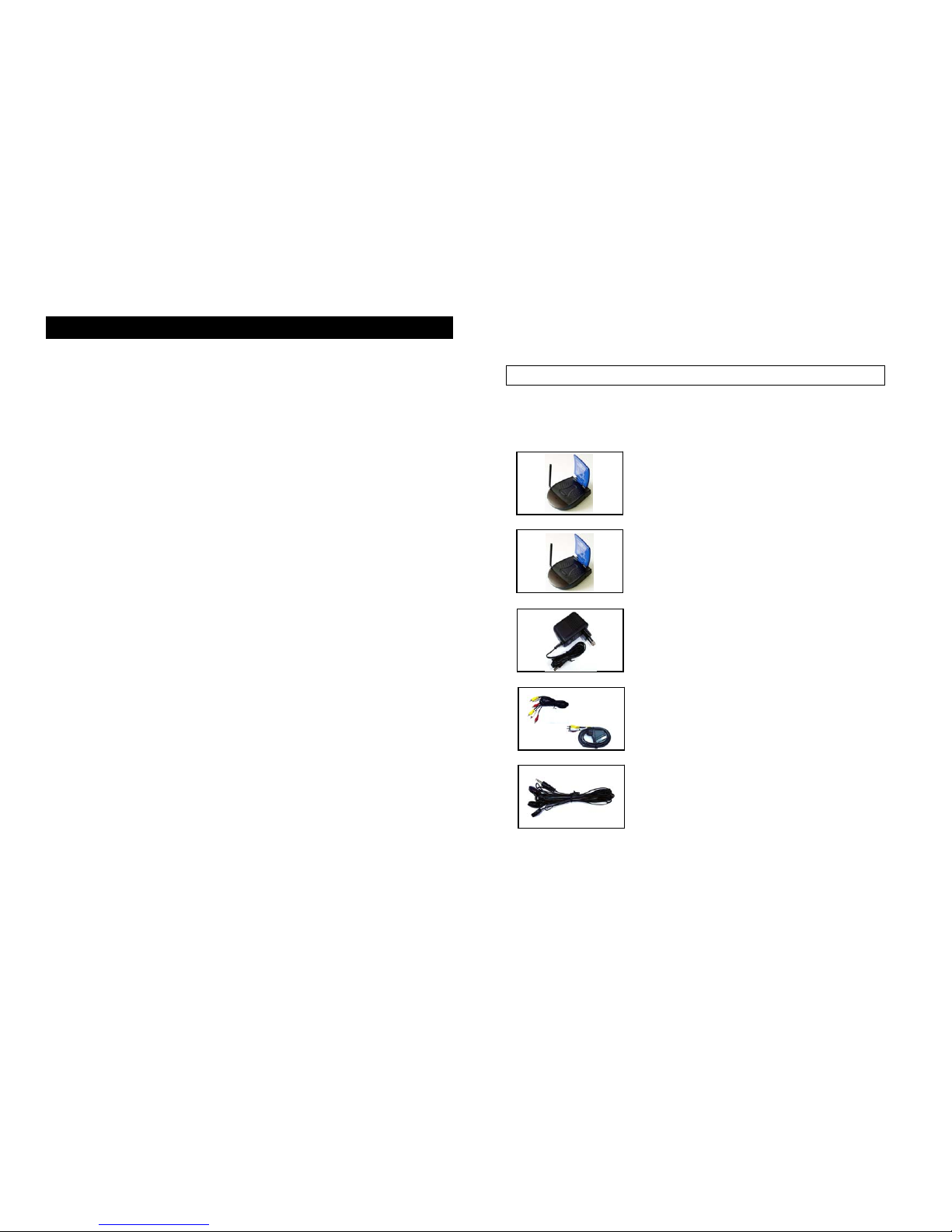
A. Checking Contents of Box
Checks to make sure that all of the items shown as below are included with
your 2.4 GHz Wireless Video Sender System. If something is missing, please
contact your dealer as soon as possible.
1. Transmitter 2283T ×1
2.Receiver 2283R X1
3. Power adapter
(230VAC to 9VDC) or (120VAC to
9VDC) DC in Jack 9V 400mA
X2
4.Cable (optional)
RCA to RCA connector A/V cable or
RCA to SCART connector. (One for
transmitter, one for receiver)
×2
5. IR extender to connect to
(optional)
transmitter's rear panel
X1
6.Owner’smanual ×1
-2-

B. Introduction to 2.4GHz Wireless AV Link
This sender system is a wireless audio/video sender that uses advanced
wireless communication technology to deliver consistently sharp audio and
video up to 100 meters away. By transmitting at a very high frequency (2.4
GHz), it avoids the crowded 900 MHz band used by many cordless telephones
and other wireless audio/video transmitters. It’s superior quality is due to wideband FM rather than AM signal modulation. Circular polarized high-gain
directional transmitting and receiving antennas are used to minimize
interference from unwanted signals and maximize the signal range.
It also integrates an UHF remote control extender to allow you to control the
audio or video source from another room using your existing remote controller.
Using sender system, you can enjoy greater convenience and security in many
ways:
General Application
• Watch the movie you rent on any TV in house without moving your VCR,
laser disc player or running messy cables.
• Watch cable or satellite programs on any TV in house.
• Listen to stereo-quality music from your receiver on any powered speakers
inside or outside the house.
• Uses multi-receivers for broadcasting to numerous TV sets in other rooms.
• Show computer images on a remote TV. (Additional equipment required)
Safety & Security Application:
• Applies as a wireless security system.
• Monitor your sleeping baby, playing children, the elderly, or the disabled on
TV using your existing camcorder.
• See who is outside the door on TV through your camera or miniature CCD
camera.
• Monitors and records meeting from another room.
• And many more uses!
-3-
■ The Using Attention
1. The outlet of the power supply must have the same voltage as the local
area.
2. Be sure the transmitter and the receiver were connected to the equipment
correctly (e.g. Connect the transmitter to the VCR, and the receiver to the
TV).
3. When switch is off from transmitter or receiver, it needs to wait for a few
seconds in order to restart again.
4. Adjust antenna plate for least interference. (Adjustment cannot rotate
more than ±180°).
5. In most situations, one set of equipment has a better feature within 100
meter. When two equipment or more is used at the same time, used
different channels. But a transmitter can be used with several receivers at
the same time.
6. The channel selectors allow you to choose the channel for best feature
and least interference.
7. When the equipment is operating, please do not use a microwave oven
near by.
8. The remote control should face to the receiver (e.g. 2283R) IR remote
control window, and the transmitter (e.g.2283T) IR remote control window
(or IR extender) should face to the source A/V equipment. The IR remote
has to be within the standard distance.
-4-
C. Panel Controls and Features of Duplex Function
Type
The following illustrations show the names of each component,
button and switch connectors on the transmitter and receiver.
(e.g.2283T/R)
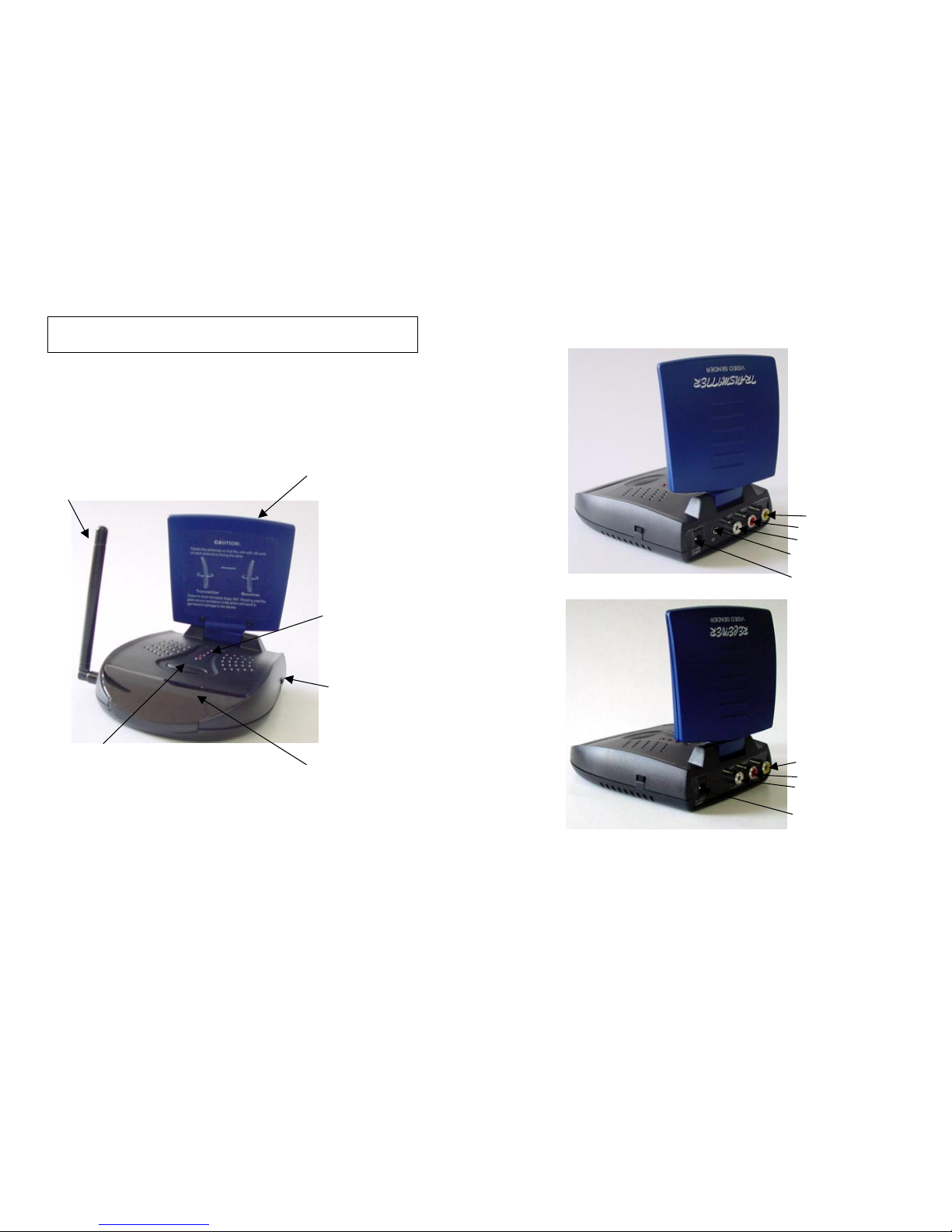
FRONT VIEW FOR TRANSMITTER AND RECEIVER
UHF antenna sends and Directional 2.4GHz
receives remote control antenna sends and
signal receives audio and
video signals
Channel indicator
lights must be set to
same number on both
transmitter and ceiver
(4 CH or 2 CH)
Power on/off switch
Channel selection button
use to find optimum Remote control window
reception, most select infrared passes through
same channel on both this to remotely control
transmitter and receiver audio/ video source
-5-
REAR VIEW FOR TRANSMITTER
REAR VIEW FOR RECEIVER
Channel select CH3
or CH4 (NTSC only)
RF output to TV
(e.g.
2058R
)
DC power input, connect
to power adapter (9VDC)
-6-
DC power input, connect
To power adapter (9VDC)
IR extender output port
Audio L in (white)
Audio R in (red)
Video in (yellow)
Audio L out (white)
Audio R out (red)
Video out (yellow)
 Loading...