

Konig SEC-DVRMON20 User Manual
SEC-DVRMON20
Short description guide of the DVR monitor. For full details of using the
DVR monitor, refer to advanced manual.
MODE D’EMPLOI
HASZNÁLATI ÚTMUTATÓ
BRUKSANVISNING
MANUAL
MANUALE
4CH DVR MONITOR
ANLEITUNG
GEBRUIKSAANWIJZING
MANUAL DE USO
KÄYTTÖOHJE
NÁVOD K POUŽITÍ
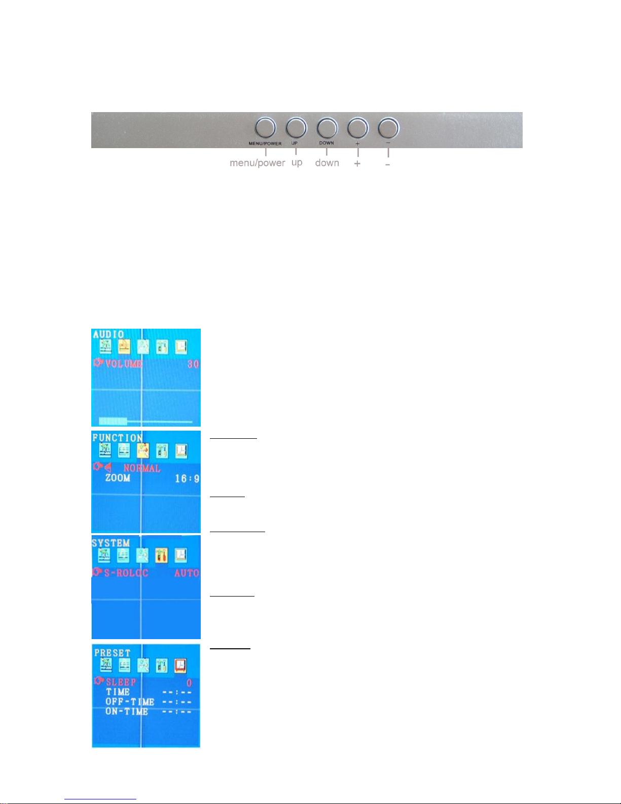
Description top panel:
MENU/POWER: A) Long press: turn on or turn off the LCD monitor (Stand-by mode)
B) Short press: used for menu of the monitor (not DVR) / move the
cursor left or right.
UP: Select the parameters of the sub menu upwards.
DOWN: Select the parameters of the sub menu downwards
+: Increase the volume or increase the value of the parameter in the sub
menu.
-: Reduce the volume or reduce the value of the parameter in the sub
menu.
Menu interface:
When you need to adjust the parameters for the LCD monitor, you can
short press “Menu/Power”. The menu will be display on the LCD
screen. Then short Press “Menu/Power” to move the cursor leftwards
or rightwards to select the option that user want to modify. Press “UP”
of “Down” to move the cursor upwards or downwards. Then, press “+”
or “-“ to increase value or reduce value. After finished the setting, press
the “Menu/Power” several times to conform and exit.
PICTURE:
“BRIGHT”: 0~100.
“CONTRAST”: 0~100.
“COLOR”: 0~100.
AUDIO:
“VOLUME”: 0~100.
FUNCTION:
Press the button “UP” or “DOWN” to change the display mode “NORMAL & DOWN” of the LCD monitor.
“ZOOM”: 16:9、4:3.
SYSTEM:
In this menu interface, users can choose the video format of display.
“S-ROLOC”: AUTO、NTSC、SECAM & PAL.
PRESET:
In this menu interface, users can close the screen automatically in two
ways. First, sets for the time of dormancy, the screen will be closed
automatically in stipulated time.
2
“SLEEP”: 0~240 minutes. The value is increased or decreased by ten. The value of “sleep”
indicates how long the LCD monitor will be turned off automatically if “OFF-TIME” is not set.
Second, sets for closedown time and time of starting the LCD monitor, the screen closes
and reveals at corresponding time point.
“TIME”: --: --, the current time of system.
“OFF-TIME”: --: --, the time of the screen turning off automatically.
“ON-TIME”: --: --, the time of the screen turning on automatically.
When modify “TIME、OFF-TIME、ON-TIME”, press “+” to adjust the value of minute and press
"—“ to adjust the value of hour.
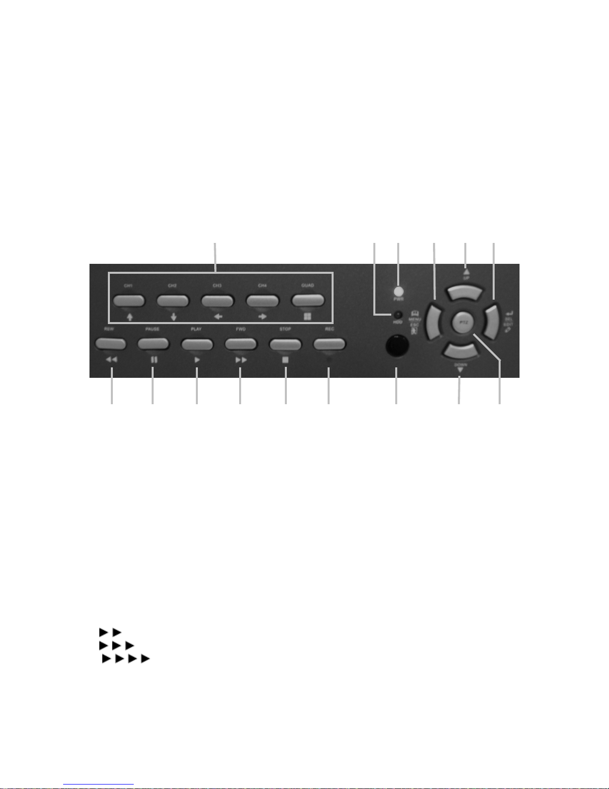
Description front panel:
2 3 4 5 6 7 10 14 15
1. CH1 , CH2 , CH3 , CH4, QUAD
Channel selection of QUAD display. Also cursor buttons for navigation through the DVR menu.
2. REWIND (REW)
Rewind picture during playback. To stop rewind, press the REW button again.
3. PAUSE
Pause picture during playback. To continue playback, push the PLAY button.
4. PLAY
Playback of recordings
Note: playback will start with the oldest unread video data and then continue playing.
5. FORWARD (FWD)
Fast forward during playback.
There are three levels of fast forward playback.
1) Play two times faster (x2) than the normal play.
2) Play three times faster (x3) than the normal play.
3) Play four times faster (x4) than the normal play.
Note: to change the fast forward playback speed level, press the FORWARD button again.
6. STOP
To stop playback.
3
1
6
7
7. RECORD (REC)
To start manual recording. To stop recording, press REC button again.
8. HDD (Hard Disk Drive) LED (RED)
System is recording or in playback mode.
9. POWER (PWR, GREEN)
System power is ON.
10. IR EYE
Receiver for remote control signal.
11. MENU/ESC (ESCAPE)
Enter the menu. Escape for exit the menu.
12. UP
To select a field in the menu, upwards
13. SELECT (SEL) / EDIT
To change values in main menu or sub menu setting.
14. DOWN
To select a field in the menu, downwards
15. PTZ (Pan, Tilt, Zoom)
To enter PTZ control
Note: The fast forward and rewind playback speeds will vary depending on the frame rate and
record quality settings, as well as the number of channels recorded.
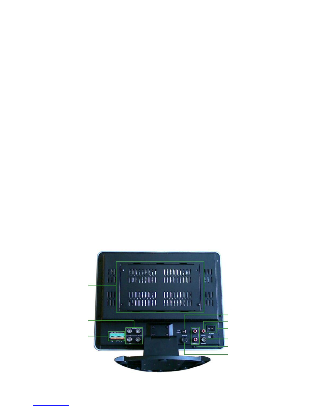
Description back panel:
8
9
4
2
3
4
5
1. DC POWER INPUT
Use only supplied AC/DC power supply.
2. AUDIO OUTPUT
Audio for playback.
3. MAIN POWER SWITCH
Switch ON or OFF the DVR system.
4. VIDEO OUT
Video output signal for another monitor.
5. AUDIO INPUT (1&2)
Audio input for microphone connection. Audio1 IN is audio for CH1 and also hearable if switched
to quad view. Audio2 IN is audio for CH2 and only hearable if CH2 is selected and not if quad
view is chosen.
6. PS2/MOUSE
Connection for mouse (included).
7. HDD POSITION
Position for HDD installing (remove the 4 screws of the grid to access).
8. VIDEO INPUT
Video input for CH1, 2, 3 and 4.
9. RS485 / ALARM / SENSOR
RS485 power line ports. To control high-speed dome camera.
ALARM input for alarm device
SENSOR input for 4 motion sensors (PIR) to start recording by motion detection
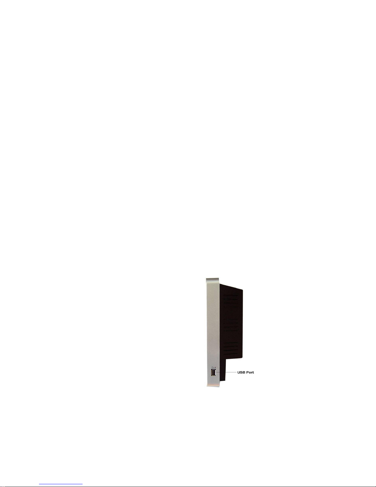
Description side panel:
USB port for back-up and software update
5
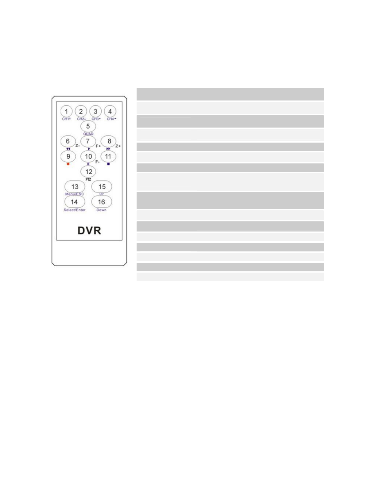
Description remote control:
1.CH1↑ Select CH1 or move cursor up
2.CH2↓ Select CH2 or move cursor down
3.CH3← Select CH3 or reduce value
4.CH4→ Select or increase value
5.QUAD
6.◄◄ (Z-)
7.► (F+)
8.►► (Z+)
9. ●
10. ▌▌ (F-)
11. ■
12. PTZ
13.Menu/ESC
14.Select/Enter
15.UP
16.DOWN
Quad view
Rewind or zoom-
Play record list or focus+
Forward or zoom+ or channel auto sequence
switch
Manual recording or stop manual recording or
Level scan
Pause or focus-
Stop playing or stop dome running
PTZ switch
Enter or exit setup menu
Modify item or increase value
Move up cursor
Move down cursor
6
Back side of hard disk
GETTING STARTED
Install a hard disk drive into your DVR.
Connect cameras (up to 4) to DVR.
Connect other peripheral devices (mouse, external motion sensors or alarm) if necessary. And
PS/2 Mouse must be connected to DVR before startup system.
Plug the power cord into the power jack on the wall.
Start TV Monitoring and Recording.
Make sure that a hard disk drive and camera(s) are properly installed.
The hard disk (IDE) jumper setting must be set to “master” jumper setting.
If the power is turned off while recording (i.e. a power failure), the DVR will enter “Power
Recovery” modes at start up, detect that it has been shut down, and then reinitiate the
recording process.
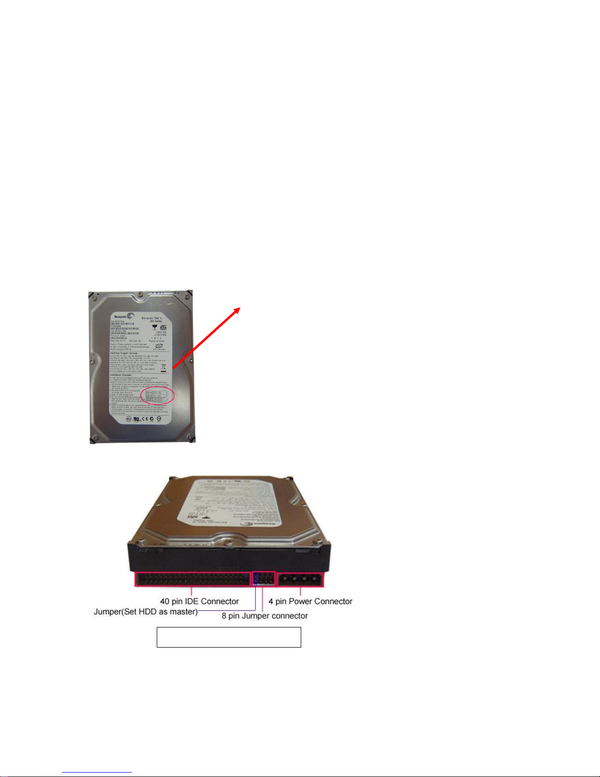
HARDWARE SETUP
IDE Hard Disk Drive Installation
(A) Make sure that HDD Jumper setting as “Master”
Before installing hard drive, set jumper as “Master”.
The master jumper setting varies depending on the hard
drive manufactures. Refer to manufacture’s manual for
master jumper setting. For example, the model of HDD
is Seagate.
(B) Connect the ribbon cable (IDE) cable & power cable
7
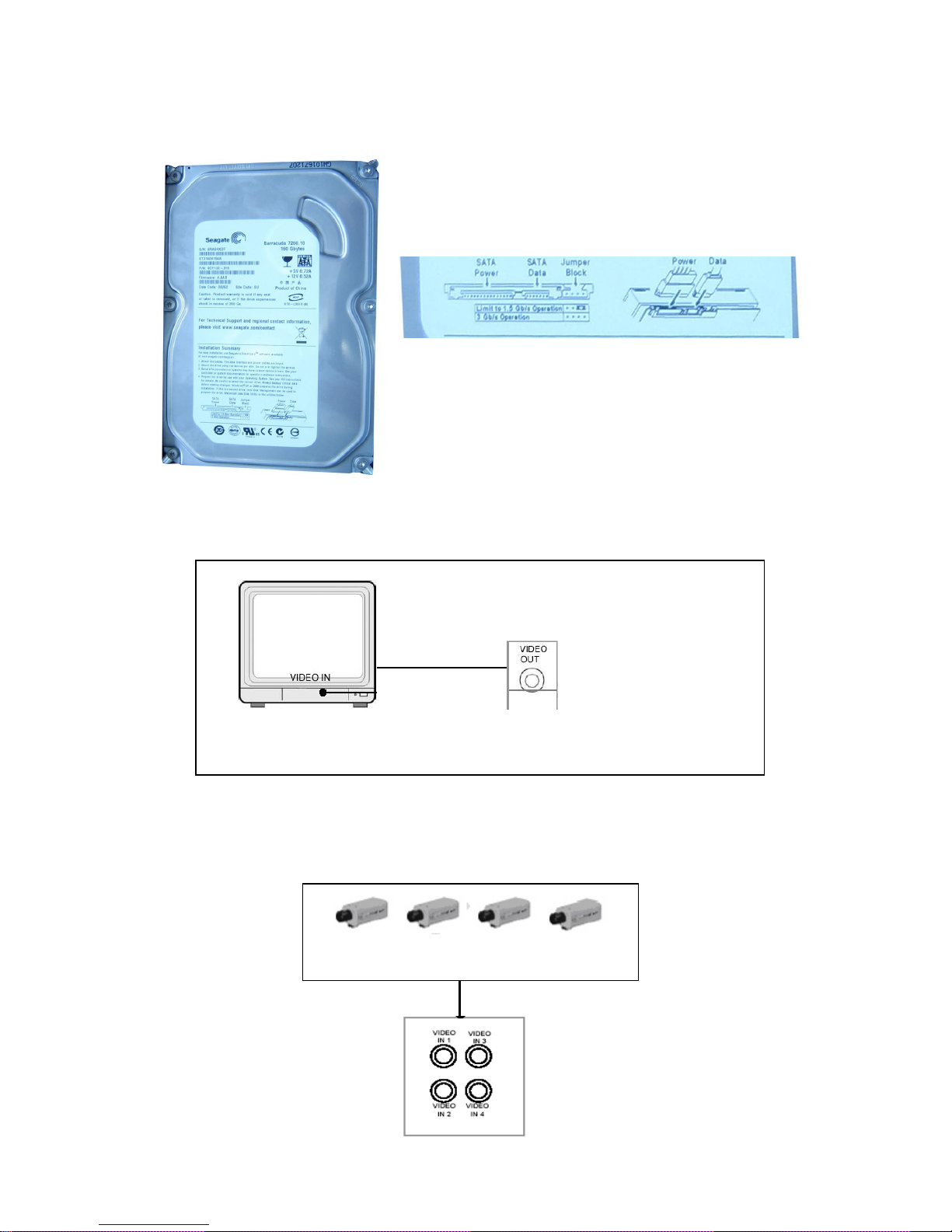
SATA Hard Drive Installation
OUT” ports on DVR
“
VIDEO IN
”
port on MONITOR
“VIDEO OUT
”
port on DVR
“
VIDEO IN
”
on
Connect the cables as follows.
Monitor Connection
To display video image from cameras on the monitor, the DVR’s video output signal should be
transferred to your TV set or monitor.
Connect “VIDEO IN” of the monitor to “VIDEO OUT” of the DVR system.
Camera Connection
Connect between “VIDEO IN” of your DVR and “VIDEO OUT” of camera with video cable and
plug in the camera’s power adapter.
Connect a monitor with “VIDEO
“VIDEO OUT” on
8
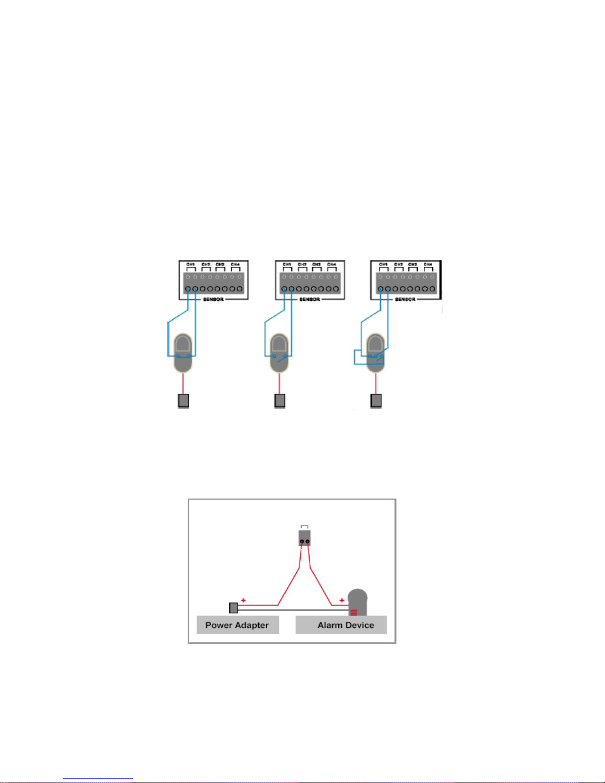
Sensor Connection
Our 4 CH DVR system can connect up to four sensors.
There are two steps for sensor installation.
(a) Connect the sensor signal lines to the signal input terminal.
(b) Connect the sensor power lines to the appropriate power source.
In general, there are three different types of sensors available in the home electrics store, where
you can buy them. (1) Normal-Close. (2) Normal-Open. (3) Normal-Close & Open. Below is the
brief diagram about how the each type of sensor is installed into DVR. The procedure for sensor
install action is as shown below.
* After you install sensor(s), change the recording mode as “Sensor record” or “MD & Sensor
record” on “RECORD SCHEDULE” in the DVR menu to enable sensor recording.
* Only the corresponding channel will record when a sensor trips, (e.g. sensor one corresponds
with channel one).
(1) Normal-Close (2) Normal-Open (3) Normal Close & Open
Alarm Connection
The DVR has an internal switch for sounding alarm. The switch is normally open, but when the
sensor is triggered, the alarm is activated as well. The circuitry is as follows.
First, connect the alarm power lines to the alarm switch terminal. Second, connect the alarm
power lines to the appropriate power source.
DVR Rear Panel
ALARM
9
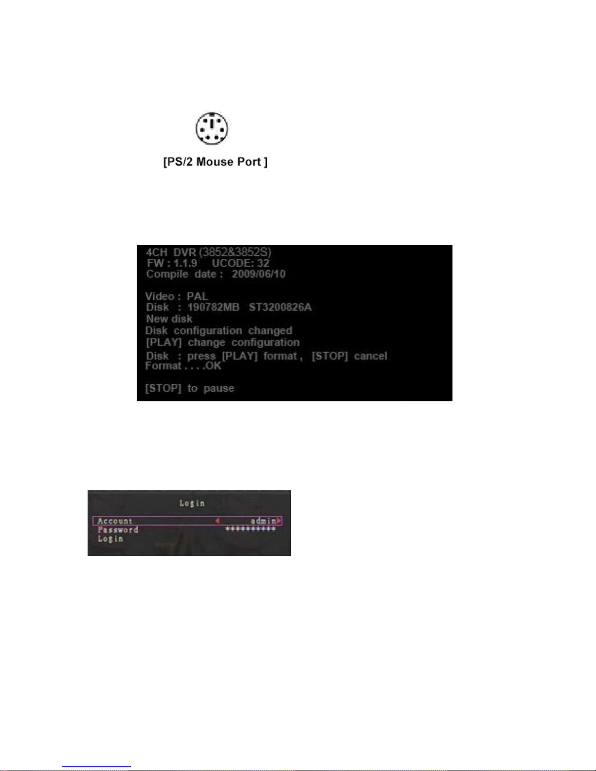
Mouse Connection
Connect PS/2 mouse with the port below on the system. And PS/2 Mouse must be connected to
DVR before startup system.
DVR Power Connection
Connect a DVR power adapter to the adapter jack at the rear panel of DVR unit.
And turn the power switch on. It will boot up the system.
If users install a new hard disk drive, it will ask for HDD formatting before a system starts to run
(Below Fig). Choose format option pressing “PLAY” button.
Below is the information of input/output voltage for the power adapter.
Input: AC 100-240V, 50/60Hz, 1.5A
Output: DC +12V == 5A
5. SETUP
After installing a new hard drive on the system,
user had better to format the hard disk drive
first. If the system includes login window, and
there will be three password levels in the
system, including admin (highest), operator,
and guest (lowest).
If the user does not login the system, he can only view live video display.
10
The system allows up to four user accounts. The administrator can set up the login name,
password and level for each user. (Please refer to Section 5.6.2 for Account Setup.)
The admin can operate everything. The operator can operate anything except examining user
accounts, formatting HDD and modifying his password level. The guest can operate live video
display and image playback, or modify some parameter value that is independent of recording. If
user has no right to modify parameter value, there will be an identifier “ ” on top right corner
of the screen.
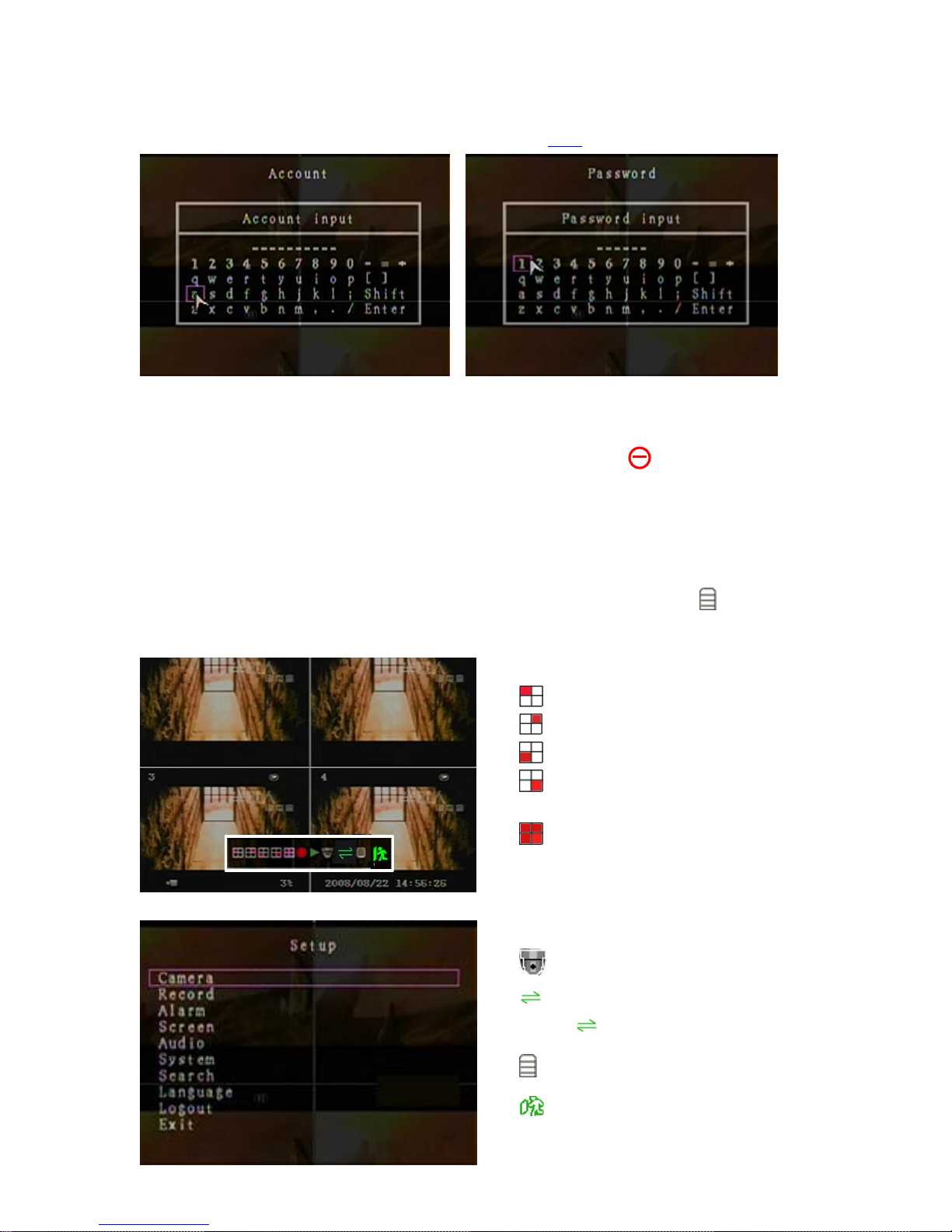
After system boot-up, hold a right mouse click button and there will be login window. Hold a left
mouse click button to click the order of “Account”, and input correct account. Then left click the
order of “Password” and input correct password. At last left click “Login” to enter system. There is
one factory-preset login “account/password” “admin/111111” at admin level. The user can use
it to login the system for the first time.
After login the system, hold a right mouse click button and there will be suggestive window
options on the monitor (Fig (a)). Hold a left mouse click button to click the icon “ ”. Or press
the MENU button to make any changes of DVR settings. You will see the screen below on the
monitor (Fig (b)).
Suggestive window options:
Channel 1 view
Channel 2 view
Fig (a)
11
Fig (b)
Channel 3 view
Channel 4 view
All channel view
● Manual recording or Stop manual
recording
► Play record list
PTZ Switch
Channel auto sequence. The icon
“ ” won’t display if the order
of “auto sequence” is “OFF”.
Menu option
 Loading...