

Konig SEC-DVR304-2 User Manual

User Manual
1
4CH Standalone DVR
SEC-DVR304-2
User Manual
2010
-08-05
Default Account & Password for SEC-DVR304-2
- User Account: [aa]
- Password: [11]

User Manual
2
【
【【
【Safety Precautions】
】】
】
Do Not touch live electrical parts.
Electric shock can be avoided. Follow the recommended practices listed below. Faulty
installation, improper grounding, and incorrect operation and maintenance of electrical
equipment are always sources of danger.
Do Not try to install equipment outdoor, when the wind and rain is
strong.
Do Not install or remove equipment outdoor ,when the weather is
raining.
Do Not try to install or operate any equipment , when the
thunderstorm happened.
Always Ground all electrical equipment and the work platform.
Prevent accidental electrical shocks. Connect power source, control cabinets, and work
platform to an approved electrical ground.
Always use the correct cable size.
Sustained overloading will cause cable failure and result in possible electrical shock or fire
hazard. Work cable should be the same rating as the torch cable or factory .
Always keep cables and connectors in good condition.
Improper or worn electrical connections can cause short circuits and can increase the chance
of an electrical shock. Do not use worn, damaged, or bare cables.
Always avoid open-circuit voltage.
The added voltages increase the severity of the shock hazard.
Always wear insulated gloves while you adjust equipments.
Power should be shut off and insulated gloves should be worn when making any equipment
adjustment to assure shock protection.
Always wear protective clothing such as long sleeve shorts while
you are installing or removing equipments.
Always Wear high, snug fitting shoes.
Always Wear clean clothes without grease or oil.
Do not wear clothing that has been stained with oil and grease. It may burn if ignited by the
heat of the arc.
Protect neighboring workers from exposure to arc radiation.
Always Wear long trousers or jeans while you are installing or
removing equipments
.
Always wear safety helmet or hard head and safety shoes before
work.

User Manual
3
Always keep the equipments in dry places.
Always wear safety harnesses/belt while you work in high places.
Always wear dry clothing and avoid moisture and water.
Always wear Public Safety Vest , while you work at night.
Make sure all electrical connections are tight, clean, and dry.
Make sure that you are well insulated and eliminate the electric static
charge.
Always wear dry gloves, rubber-soled shoes, or stand on a dry board
or platform.
Always Follow recognized safety standards.
Always wear correct eye, ear, and body protection.
Always have second person on-site, while you work in the darkness
places, poor ventilation places and high places.
Make sure that you are well protected against arc flashes,
mechanical injury, or other mishaps.
Make sure that the polarity of wire is correct, before installing
equipments.
Always handle equipment with care.
Do Not block the ventilation of equipment.
Do Not put the magnetic parts around the Equipment.
Do Not put the objects on top of equipment.

User Manual
4
LIMITATION OF LIABILITY
THIS PUBLICATION IS PROVIDED “AS IS” WITHOUT WARRANTY OF
ANY KIND, EITHER EXPRESS OR IMPLIED, INCLUDING BUT NOT
LIMITED TO, THE IMPLIED WARRANTIES OF MERCHANTIBILITY,
FITNESS FOR ANY PARTICULAR PURPOSE, OR NON-INFRINGEMENT
OF THE THIRD PARTY’S RIGHT.
THIS PUBLICATION COULD INCLUDE TECHNICAL INACCUACIES OR
TYPOGRAPHICAL ERRORS. CHANGES ARE ADDED TO THE
INFORMATION HEREIN, AT ANY TIME, FOR THE IMPROVEMENTS OF
THIS PUBLICATION AND/OR THE CORRESPONDING PRODUCT(S).
Warning
This is the symbol for indicating
any potential hazard, risk or
condition requiring special
attention. The user need to refer
to the important operating and
maintenance or servicing
instructions.
Caution
The lighting flash with an arrow
head symbol, in an equilateral
triangle, is intended to alert the
user. There is dangerous
“voltage” presence near by the
product’s enclosure which may
be risk of person.
information
This is the symbol for notice
you that more information in the
other pages or additional
information.
Environmental-friendly
This is the symbol for recycling ,
in order to create the green
planet.

User Manual
5
DISCLAIMER OF WARRANTY
IN NO EVENT SHALL THE SUPPLIER BE LIABLBE TO ANY PARTY OR ANY
PERSON, EXCEPT FOR REPLACEMENT OR REASONABLE
MAINTENANCE OF THE PRODUCT, FOR THE CASES, INCLUDING BUT
NOT LIMITED TO THE FOLLOWINGS:
ANY DAMAGE OR LOSS, INCLUDING BUT WITHOUT LIMITATION,
DIRECT OR INDIRECT, SPECIAL, CONSEQUENTIAL OR EXEMPLARY,
ARISING OUT OF OR RELATING TO THE PRODUCT;
PERSONAL INJURY OR ANY DAMAGE CAUSED BY INAPPROPRIATE
USE OR NEGLIGENT OPERATION OF THE USER;
UNAUTHORIZED DISASSEMBLE, REPAIR OR MODIFICATION OF THE
PRODUCT BY THE USER;
ANY PROBLEM, CONSEQUENTIAL INCONVENIENCE, OR LOSS OR
DAMAGE, ARISING OUT OF THE SYSTEM COMBINED WITH THE
DEVICES OF THE THIRD PARTY;
ANY CLAIM OR ACTION FOR DAMAGES, BROUGHT BY ANY PERSON
OR ORGANIZATION BEING A PHOTOGENIC SUBJECT, DUE TO
VIOLATION OF PRIVACY WITH THE RESULT OF THAT
SURVEILLANCE-CAMERA’S PICTURE, INCLUDING SAVED DATA, FOR
SOME REASON, BECOMES PUBLIC OR IS USED FOR THE PURPOSE
OTHER THAN SURVEILLANCE.

User Manual
6
TABLE OF CONTENTS
【
【【
【Safety Precautions】】】】 .....................................................................................................2
LIMITATION OF LIABILITY ..................................................................................4
DISCLAIMER OF WARRANTY..............................................................................5
【
【【
【Chapter 1. Overview】】】】 ...................................................................................................9
1. Introduction..............................................................................................................9
1.1. Features...............................................................................................9
1.2 Packing list.........................................................................................11
1.3 Components.......................................................................................12
【
【【
【Chapter 2. Installation and connections】】】】.............................................................18
2 Installation and connections:.............................................................................18
2.1 Hard Disc:...........................................................................................18
2.2 Camera & Monitor:...........................................................................20
2.3.PTZ CAMERA: ...................................................................................21
2.4. keyboard:...........................................................................................22
2.5.RS-485 keyboard or Terminal........................................................22
【
【【
【Chapter 3.OSD SETUP】】】】.............................................................................................23
3.1 Structure of the OSD menu. ............................................................................23
3.1.1.Log in & Log out: ..........................................................................25
3.1.2. Status:.............................................................................................27
3.1.3 Volume:............................................................................................28
3.1.4. Video adjustment:........................................................................29
3.1.5. VGA DISPLAY................................................................................31
3.1.6.Backup device:..............................................................................31
3.1.7.SETUP(Administrator) .................................................................33
3.1.8.Pre-camera......................................................................................35
3.1.9. Camera............................................................................................37
3.1.9.1.Video loss :..........................................................................40
3.1.9.2. Motion detection:..............................................................42
3.1.10. Alarm.............................................................................................46
3.1.11.SEQ DISPLAY(Switching channel).........................................49
3.1.12. Scheduled Record.....................................................................51
3.1.13. H.D.D(HARD DISC) ....................................................................55
3.1.13.1.Advanced HDD setup:....................................................61
3.1.14.Password ......................................................................................63
3.1.14.1.ADV-User Setup:..............................................................66
3.1.15.System setup(Time zone).........................................................69

User Manual
7
3.1.16. RS232/422/485 ............................................................................72
3.1.17 Network............................................................................................................75
3.1.18. E-mail setup:...............................................................................79
3.1.18.1. FTP Setup:........................................................................82
3.1.18.2. Advanced Network Setup: ...........................................84
3.1.19.Factroy Default............................................................................87
3.1.20. ESC................................................................................................87
3.1.21. Software Upgrade (Administrator)........................................88
3.1.22.System Shutdown (Administrator).........................................90
Digital Zoom .................................................................................................91
【
【【
【Chapter 4. PTZ Control】】】】............................................................................................92
【
【【
【Chapter 5.Search/Playback/Archive】】】】 ....................................................................94
5.1 Description:..........................................................................................................94
5.2.Search By Time...................................................................................................96
5.3 Search By Event / Log Display.....................................................................103
5.4. Smart Search....................................................................................................106
5.5. Search Archived Files....................................................................................110
【
【【
【Chapter 6. Remote Access】】】】 ...................................................................................112
6.1 PC Remote Access...........................................................................................112
6.1.1.System Requirements of Remote PC....................................112
6.1.2.Before Logging On .....................................................................113
6.1.3.Firefox............................................................................................114
6.1.5.Remote Display and Operations.............................................117
6.1.5.1.Control panel of Main Screen.......................................120
6.1.5.2.Search & Playback ..........................................................122
A.Search By Time....................................................................122
B.Search By Event..................................................................123
C.PTZ Control..........................................................................124
D.Server Configuration...........................................................125
E.Add New Server...................................................................125
F.Modify Server........................................................................126
G.Delete Server.......................................................................126
H.Configure Server Property.................................................127
I.Camera...................................................................................128
J.Motion ....................................................................................129
K.Video Loss............................................................................130
L. Alarm.....................................................................................131
M.SEQ Display ........................................................................132

User Manual
8
N. Schedule..............................................................................133
O. HDD......................................................................................134
P. Password..............................................................................135
Q. System.................................................................................136
R. RS232/422/485...................................................................137
S. Network................................................................................138
T. Email.....................................................................................139
U. FTP.......................................................................................140
【
【【
【Chapter 7. PDA/Mobile Phone Remote Access】】】】...............................................141
Appendix...............................................................................................................................1
Appendix A-Split Window Screen...........................................................................1
Appendix B – Keyboard Control Protocol............................................................2
Appendix C – Keyboard Control Simulator..........................................................4
Appendix D – M4V/H.264 to AVI Conversion Utility...........................................5
Appendix E – Time Zone Table................................................................................7
Appendix F – Recording Table ..............................................................................10
Appendix G-Specifications.....................................................................................12
Appendix H-compatible device table...................................................................14
Appendix I- Applying free DDNS Host from internet.......................................16

User Manual
9
【
【【
【Chapter 1. Overview】】】】
1. Introduction
The H.264 digital video/audio recorders are designed for use within a
surveillance system with limited space, and are a combination of a hard disc
recorder, a video multiplexer, and a web server.
To achieve the highest inter-connectivity and inter-operability, this series of
digital video/audio recorders are all based on industry-leading front-end to
back-end surveillance infrastructure. With state-of-the-art system
architecture, powerful compression/decompression engine, and intelligent
recording algorithms, hexaplex operation can be easily achieved without
sacrificing the increasing demands of functionality, performance, reliability, and
availability in the surveillance industry.
1.1. Features
H.264 Compression for better video quality & smaller record size
4-CH H.264 DVR with Hexaplex operation – record, live view, playback, backup, control, & remote
access
Support DDNS.
Live view support 3-D de-interlace & de-noise
Up to D1 resolution
Double recording rate (Full-D1: 60 / 50 IPS, Half-D1: 120 / 100 IPS, CIF: 240 / 200 IPS)
Mouse Driven GUI Interface
Two way Audio communication capabilities
Audio Broadcasting facilitates administrator easy to manage multiple DVR through one IE
Simple USB Backup
External USB DVD-RW & USB HDD supported (Backup)
Digital Zoom 2X / 4X
Built-in VGA
Supported Multi-language
Smart search: provides smart search of “Mark specific Area” for quicker search
Digital watermark to Prevent film to be altered.
Playback search by time or event (alarm, motion, video loss)
1 SATA HDD supported > 2TB.
USB2.0 * 1 for video/audio backup to versatile USB2.0 storage devices , USB1.1 * 1 for
mouse operation
Multi-Operation interface: remote controller, touch board, and mouse operation

User Manual
10
RS-485 for PTZ, keyboard control
Immediately remote trigger I/O devices via IE remote software & Mobile Phone
Remote view via Mobile Phone/IE/Firefox
OCX SDK available for the integration with different applications
Playback recorded video via IE / Firefox software (Max. 64chs.)
Free video player for backup vide
o
Support smart phone no need install application.
For more information , please refer to Appendix.
User Manual
11
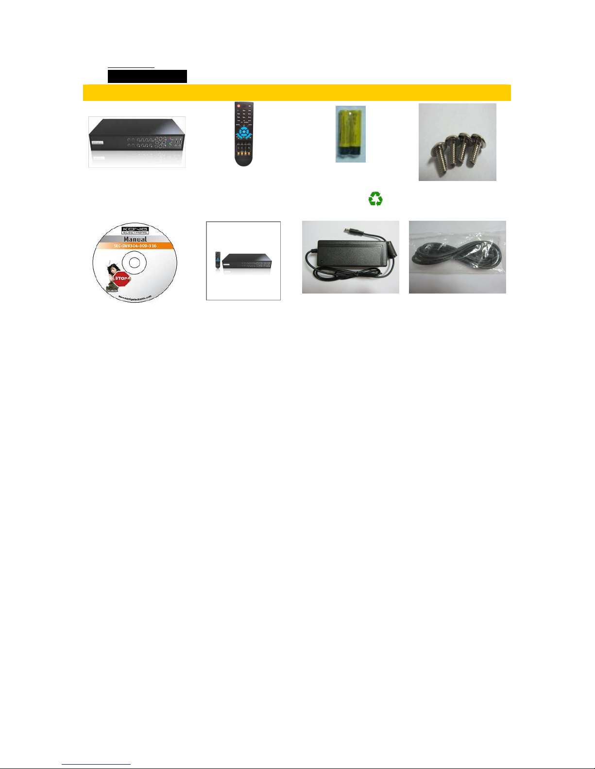
1.2 Packing list
Packing list
SEC-DVR304-2 Remote Controller
AAA Battery
Screws
SEC-DVR304-2
Quick Reference
2010-07-09
CD
Quick Guide
Power Adapter
Power Cord
User Manual
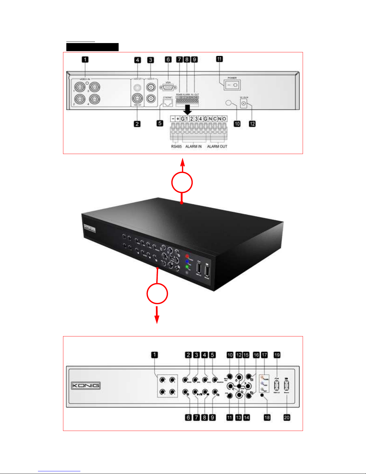
12
1.3 Components
A
B

User Manual
13
Area A (Front view)
No. Symbol Button Functions
1 1-4 Alpha-numeric For selecting Channels.
Also, it can be used for typing text and number,
when use mobile functions.
2 Mode MODE
For toggling between live mode and playback
mode in main screen display.
Also, as the function of “backward/slow
backwrad”,when you used the playback mode.
3 SEQ SEQ For changing channels.
4 CALL CALL
For switching to or return from full screen
display of the focus camera in main screen
display.
5 SEARCH SEARCH For displaying the search menu.
6 REC RECORD
For manual recording. To stop manual
recording, press button once again.
7
Play/Pause
For playing the recorded images, or pausing
the playback.
8
Stop For stopping the playback.
9
Copy
For copying the playback images to the storage
device connected to the USB port. Press this
button once to stop copying.
10 Menu/Esc MENU / ESC
For displaying the main menu or exit to
previous page.
11 Page Page
In main screen display, press this button to
enter/exit PTZ control if the focus camera is a
PTZ camera.
12 ▲/BS Up/BS As the function of moving up or focus window
in normal operation.
*In PTZ control, it used for tilting up the

User Manual
14
camera.
**In text editing mode, the function as
“**backspace” key.
13 ▼/DEL Down/DEL
As the function of moving down or focus
window in normal operation.
*In PTZ control, it used for tilting up the
camera.
**
In text editing mode, the function as “del” key.
***In playback mode, it used for single step.
14 ◄,► Left/Right
In PTZ control, it is used for panning the
camera.
In playback mode, the function as fast
backward/forward.
In the other screens, it is used for cursor or
focus window.
15 ENTER ENTER
This button is used as “enter” key in normal
operation.
*In PTZ control, this button is used to start/stop
the selected PTZ control mode.
16
+ / -
Split Windows For next/previous split-window display.
LED indicator/ Main power, HDD and Network access
indicators.
17
18 LEDs
IR sensor For receiving signal from I/R remote controller
19 U.S.B port For USB 2.0 compatible storage device
20 U.S.B port For USB MOUSE connection.
For detailed information, please refer to appendix.
User Manual
15
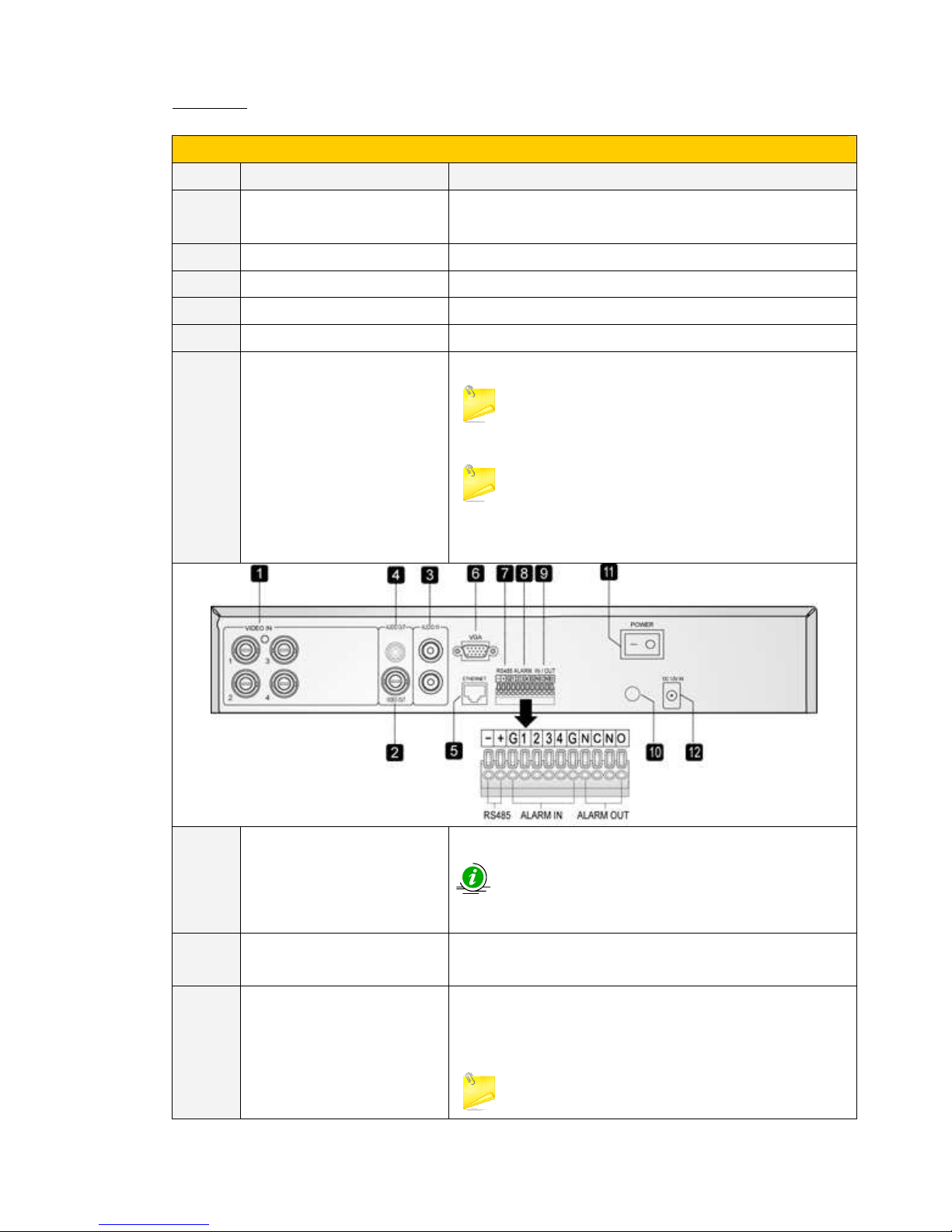
Area B (Rear view)
No. Connector Functions
1 Video Input(camera) (1-4ch) For Camera video input(BNC connector/internal 75Ω
termination).
2 Video output(Main out) For video output(BNC connector)
3 Audio input For audio input(RCA connector)
4 Audio output (AUDIO) For audio output(RCA connector)
5 Ethernet socket For internet connection
6 VGA For VGA output (optional D-SUB 15-pin female connector).
There won’t be video signal for MAIN OUT BNC
connector if VGA is connected.
If you would like to switch the connector from VGA into
MAIN OUT or from MAINOUT into VGA , you have to restart
the DVR, after you finished the connection.
7 RS-485 For RS-485 compatible PTZ camera(s) or keyboard.
For more information , please refer to installation
and removal(RS-485 setting).
8 Alarm Input (ALARM IN 1-4) For Connecting to external devices such as sensors or door
switches.
9 Alarm Output
(ALARM OUT NC/NO)
For connecting Alarm.
(Normally Closed (NC) (left), for alarm output) (Normally
Open (NO) (right) , for alarm output)
NC and NO only have 4 ports, Make sure that it is
User Manual
16
in right position, before connection.
Please note that only one of the NC or NO
connectors can be connected .
10 IR extension port(IR optional) For connection IR receiver(Optional)
11 Main Power switch(DC +12V) For DC 12V POWER SWITCH .
12 Power cord socket(DC +12V) For DC12V POWER INPUT.
For more information , please refer to appendix.
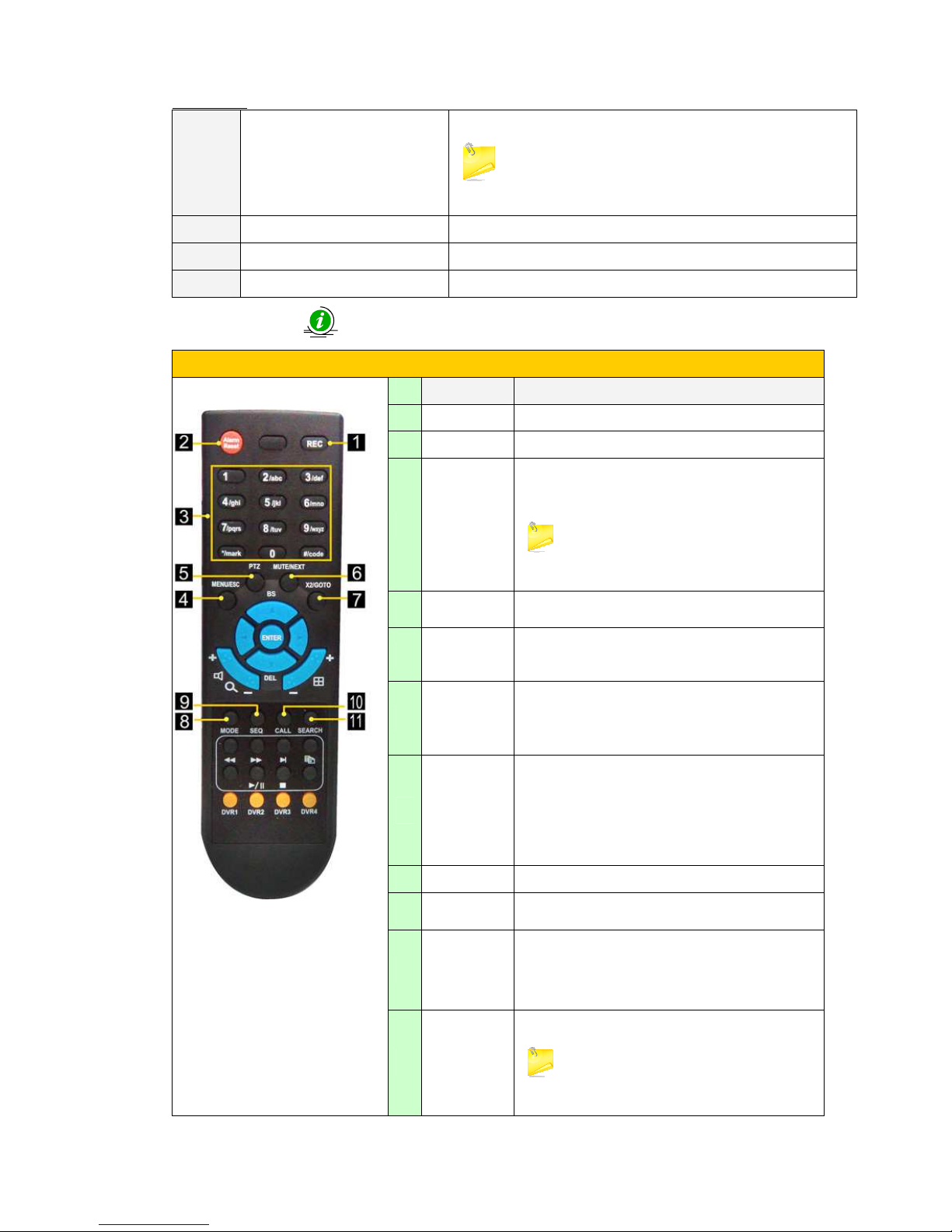
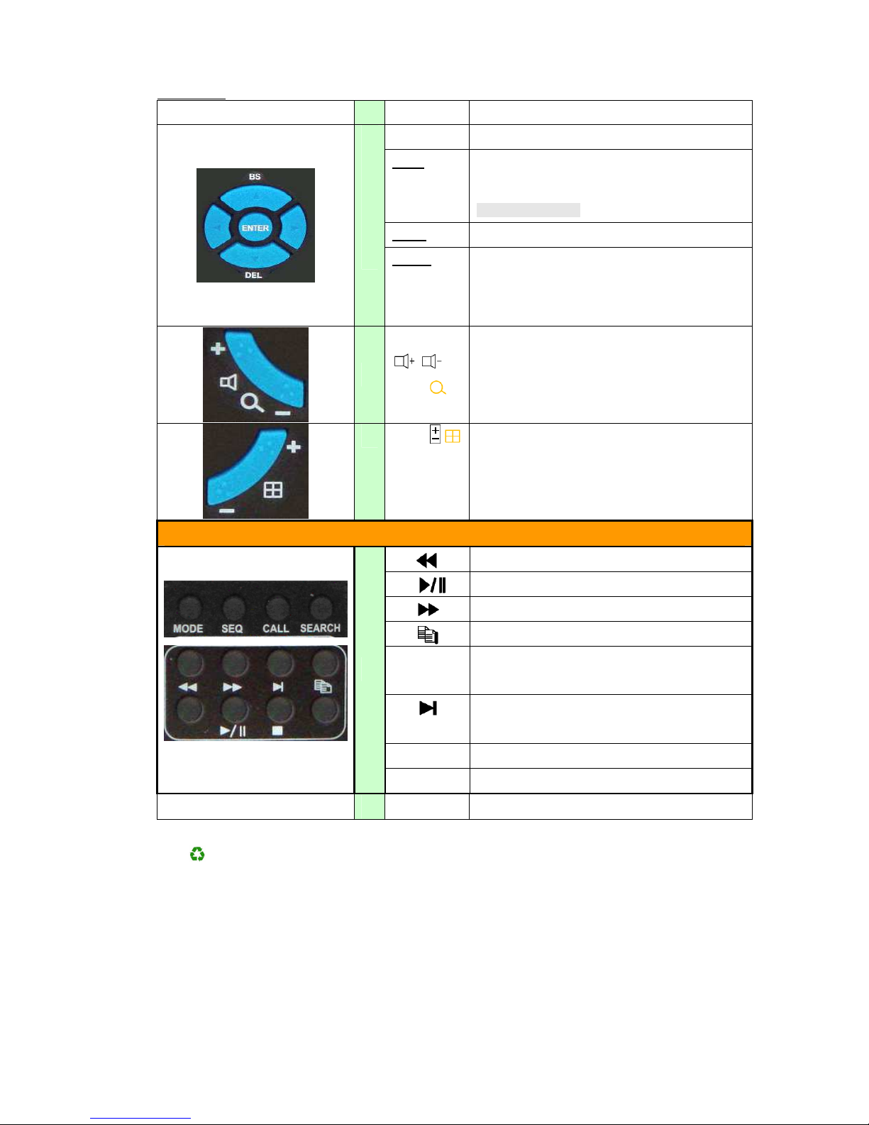
Remote Controller
No
Symbol Functions
1
REC Press to start the recording.
2 Alarm Reset Press to restore the alarm status to default.
3
Numeric/
alpha button
(1-9, 0, *, #)
For camera selection ,and also it can be used for
entering text and numbers.
The symol “#’ is also used for page down in
multi-split-window displays.
4
MENU/ESC For displaying the OSD menu and exit.
5
PTZ
Click to access the PTZ control when there is a
PTZ camera supported.
6
Mute/Next
Audio mute and the “Next” is used for choosing
next text when you typing the text in Text input.
7
X2/
GOTO
*Zoom in/Zoom out(Digital Zoom (X2/X4))
*Click to view the image taken by PTZ camera at
its preset location.
8
Mode Press to switch between live and playback mode.
9
SEQ For changing channels.
10
Call
To call monitor and for video only(For switching
to or return from full screen display of the
focus camera in main screen display).
11
Search
To search the record video.
There are five types of search modes:
search by time, search by event, smart search,
User Manual
17
search archived files.
Enter For confirming the options or goto certain pages.
▲/BS: Click to move up or backspace for text/numeric
entry.
*BS: BACKSPACE
◄ : ► LEFT/RIGHT BUTTON.
12
▼/DEL
Click to move down or delete text for text/numeric
entry.
13
/ /
(Vol/Zoom) +/- Buttons.
*In PTZ control, press these buttons
to zoom in/out the camera.
14
/
To switch between different screen layouts.
Playback
Fast backward 2X,4X
Click to play or pause the playback.
Fast Forward 2X,4X,8X,16X
To copy the image to an external storage device.
Stop the playback, click again will back to normal
record mode.
Single Step the system will pause first and then
jump to next step.
MODE
Fast/slow backward 2x/4x/8x/6X
15
SEQ
Fast/slow forward 2x/4x/8x/6X
DVR1 – DVR4
16
Reserved
For environmental-friendly, please recycle the battery or use rechargeable
battery.
User Manual
18
【
【【
【Chapter 2. Installation and connections】】】】
2 Installation and connections:
2.1 Hard Disc:
Caution
!!!!
Do NOT install or remove hard drive while DVR is running!
Warning
!!!!
Make sure that you already turn off the power and disconnect the power
cord, Before performing any services or maintenances.
Warning
!!!!
Do NOT use electric screw-driver for installing or removing Hard Disc,
when you installing or removing Hard disc, or you will damage the Hard
disc, Use screw driver manual only.
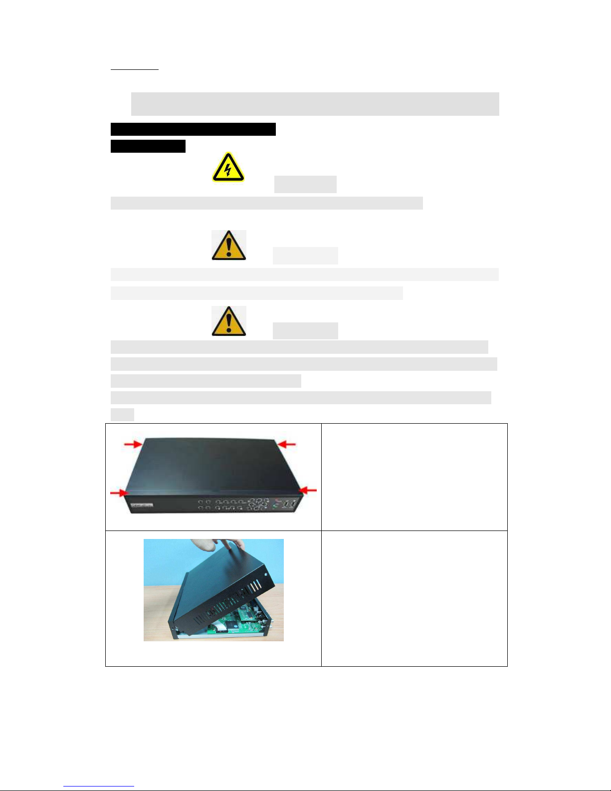
Make sure to install one SATA hard disc (Max. storage size 2TB) inside the
DVR
Step1.
Loosen 4 screws on the two sides of the
case (Using cross screw driver),(As
shown).
Step 2.
Remove the top cover by lifting and slide
back.(by hand)
User Manual
19
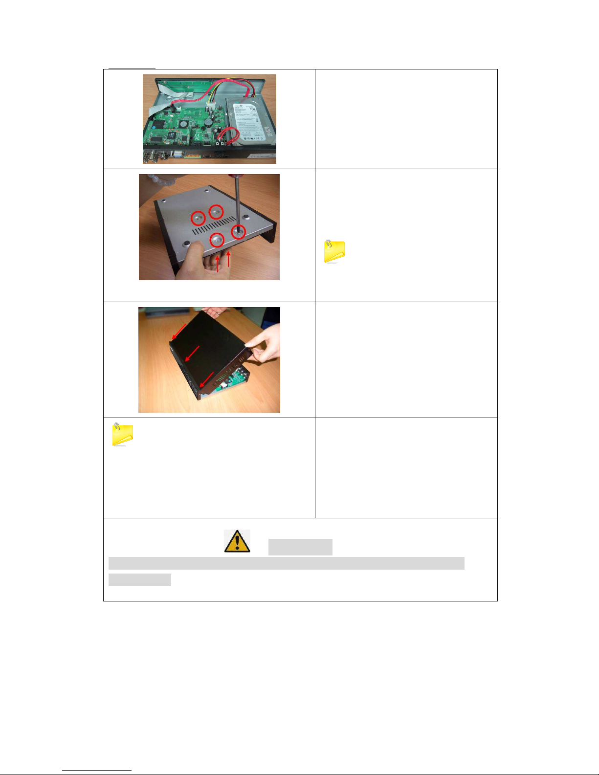
Step 3.
Connect Hard Disc to the cable of SATA.
Step 4.
Install the hard disc in the bracket, and
tighten 4 screws on the side of hard
disc(hand tight).
Before install the cover, make sure
that the cable all in the correct position
without loosing parts or cables.
Step 5.
Install the top cover and tighten 4 screws
on the side of top cover(hand tight).
The HDD must be formatted before use.
For more information of H.D.D format, please
refer to Chapter 3.1.17.
(the system will detect the H.D.D and format
automatically, in the initial starting).
Step 6.
Check the top cover to see it is in good
condition, and then connect the power
cord.
Warning
!!!!
Make sure that the switch is in off position , before you connect the
power cord.
User Manual
20
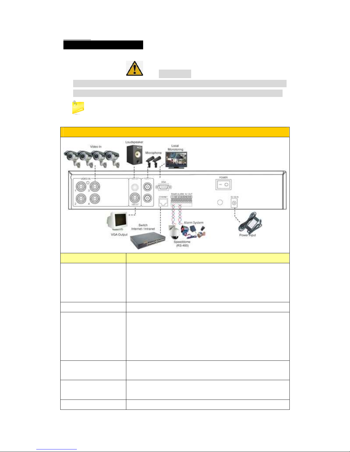
2.2 Camera & Monitor:
Warning
!!!!
Make sure that the switch is in off position ,before you connect the
power cord. and also make sure that the power is correct of adaptor.
Make sure to set the NTSC/PAL Selector Switch on the main board according to the
local TV system for the system to work correctly.
Rear Panel Connection
Items
Description
Camera
Connect the camera video input connectors to the
video outputs from system cameras or other composite
video sources via coaxial cables.
The internal 75Ω termination is always ON.
Power connector
Connect power source to DC 12V,3A
Monitor(VGA)
Connect the main monitor output connector (BNC) to a
surveillance TV monitor, or connect the VGA output
connector to a VGA monitor.
The TV/VGA monitor displays selected live or recorded
cameras in any available split window format.
Monitor(Main out)
Connect the main monitor output connector (BNC) to a
surveillance TV monitor.
Audio
input(Optional)
Connect the audio input connector to the audio line-out
from system cameras or other audio sources.
Audio
Connect the audio output connector to the audio line-in
User Manual
21
output(Optional)
from speakers
Alarm
inputs(Optional)
Connect the alarm inputs to NC and/or NO type of
alarm signals.
Alarm
outputs(Optional)
Connect the alarm output #1 to NC type of alarm signal,
or alarm output #2 to NO type of alarm signal.
Please note that only one of the NC or NO
connectors can be connected only.
Ethernet(Optional)
Connect the Ethernet connector to a standard
twisted-pair Ethernet cable for remote access via LAN
or internet.
I/R remote controller
The user may use I/R remote controller to control the
digital video/audio recorder
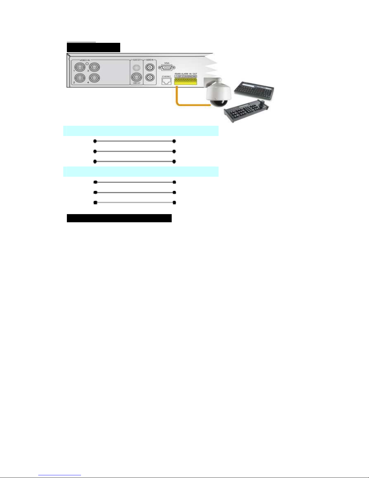
2.3.PTZ CAMERA:
Connect the RS-485 connector to PTZ camera(s) via the appropriate
cable. The system supports a variety of different PTZ cameras,
including Pelco D protocol Dome, SamSung SCC-641P, Kalatel Cyber
Dome, Bosch AutoDome, etc.
But different PTZ cameras can coexist in a system only if they support
the same protocol.
Please make sure to set the PTZ ID of the camera(s), and setup
the camera and RS-232 or RS-422/485 accordingly.
User Manual
22
2.4. keyboard:
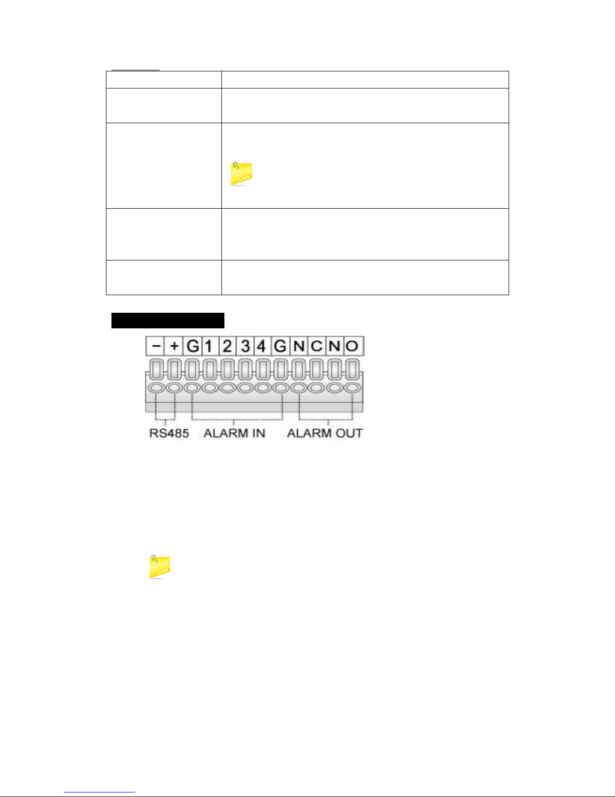
2.5.RS-485 keyboard or Terminal
Connect the RS-485 connector to a RS-485 keyboard controller or
VT-100 terminal via the appropriate cables.
Please refer to the diagram above for the correct connection (as shown).
For Keyboard
RS485+
TxD+
RS485-
TxD-
GND
GND
For PTZ Device
RS485+
RxD+(Data+)
RS485-
RxD-(Data-)
GND
GND

User Manual
23
【
【【
【Chapter 3.OSD SETUP】】】】
3.1 Structure of the OSD menu.
User Manual
24
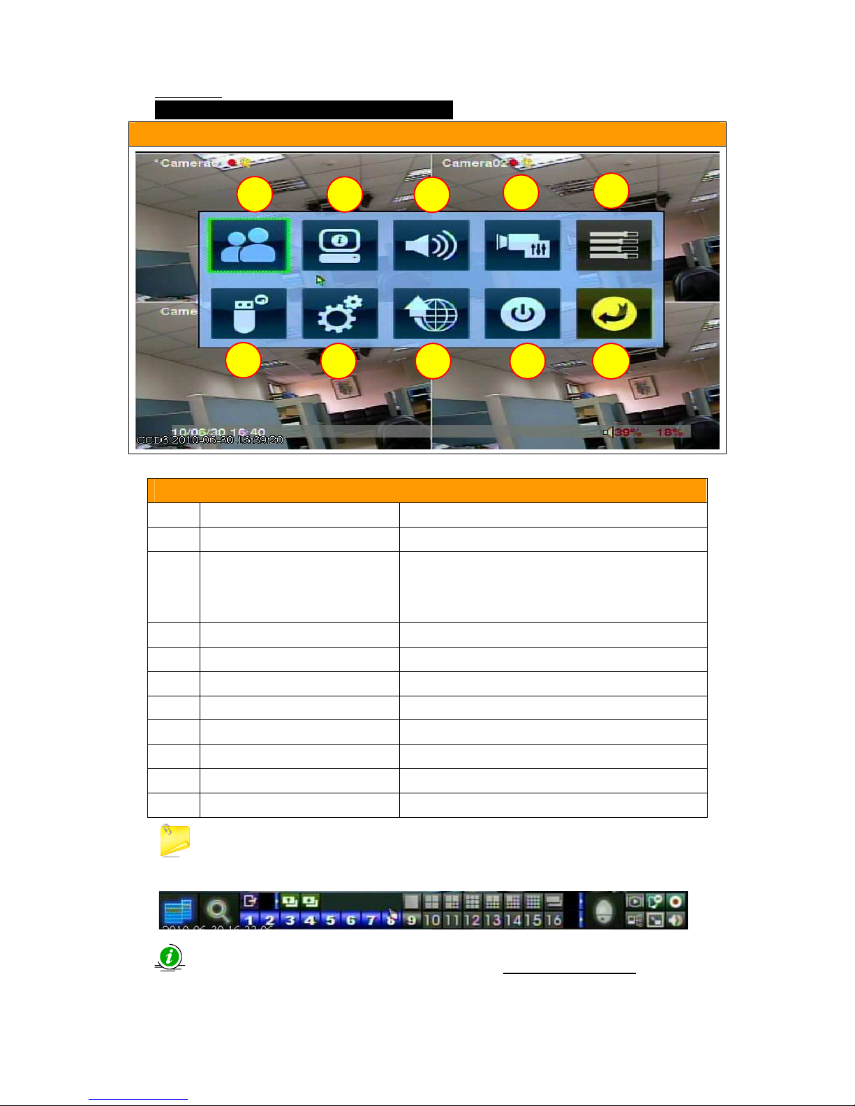
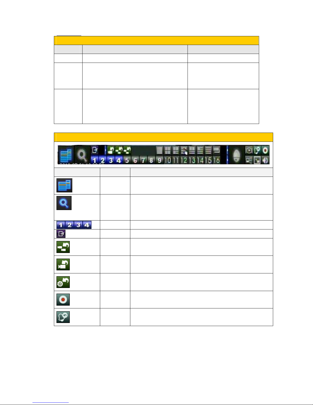
3.1.0. OSD DISPLAY MENU(MAIN PAGE)
OSD DISPLAY MENU(MAIN PAGE)
OSD Display menu(main page)
NO. Name Functions
1 Login & logout
For entering system
2 Status
For displaying the status of Alarm,
camera, motion as well as the version of
software.
3 Volume
For displaying the volume of system.
4 Video adjustment**
For adjusting the setting of screen.
5 VGA Display
For adjusting the resolution of VGA.
6 BACKUP Device
For testing the backup devices.
7 SETUP
For setting the system
8 Software upgrade
For Software upgrade
9 Shutdown button
Shutdown the system
10 ESC
EXIT or back to previous page
For video adjustment option, there will display the basic operation
menu in the bottom of screen ,as shown:
.
For more information, please refer to chapter Video Adjustment.
1 2 3
4
5
6
7 8 9
1
0
User Manual
25
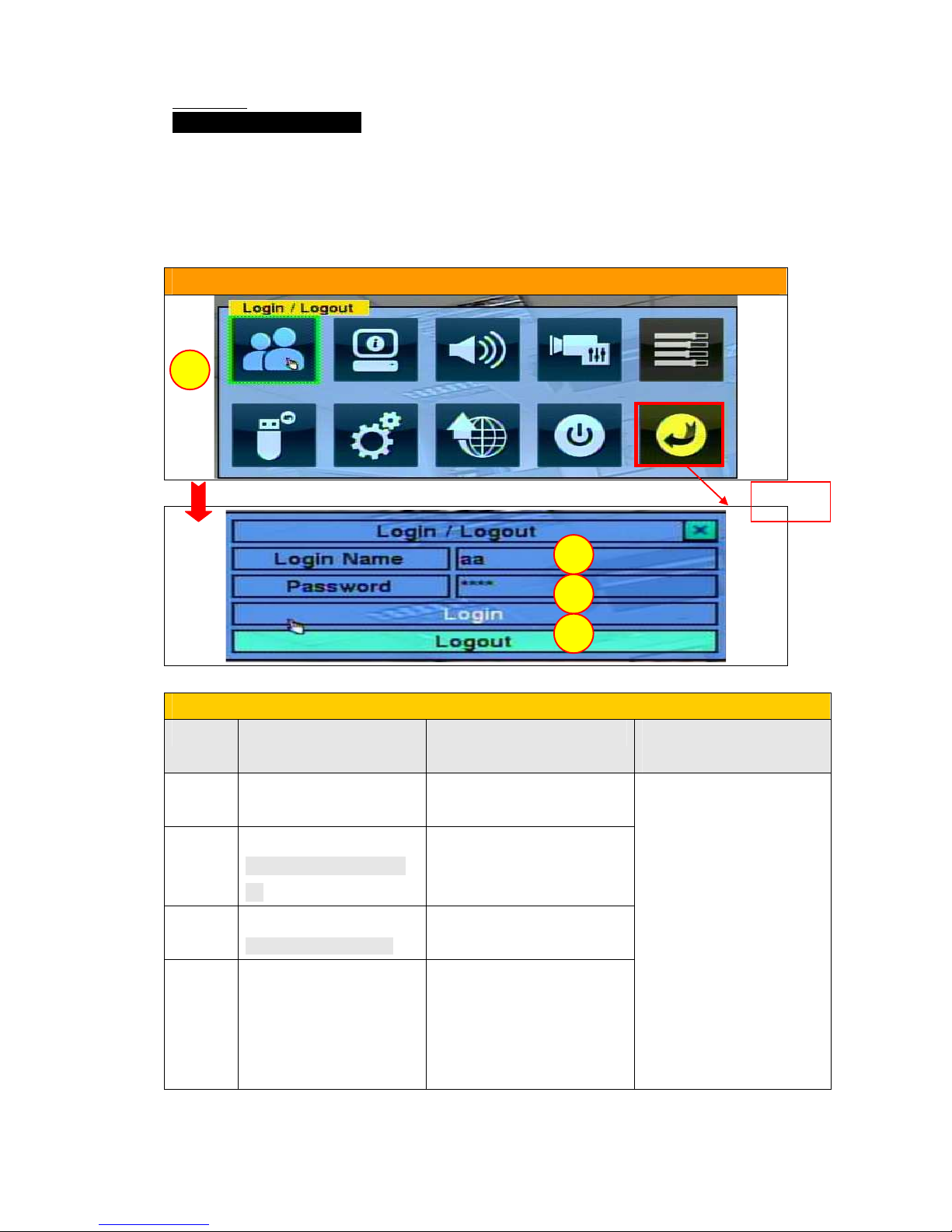
3.1.1.Log in & Log out:
Description:
There are three password levels in the system, including Administrator
(highest), Supervisor, and Operator (lowest).
If the user does not login the system, he/she will be treated as “Guest”
and can only view live video display.
OSD DISPLAY MENU(LOG IN& LOG OUT)
LOGIN & LOGOUT PROCEDURES
STEPS
MOUSE Button/Remote control
Text input for remote
control
STEP 1 Click on “LOGIN &
LOGOUT” icon.
Press “Menu” button.
STEP 2
Key in the Login name
*Default login name:
aa
Press “Enter” button to
display the Login/logout
options.
STEP 3
Enter the password
*Default password:11
Press▲▼ button to change
the highlighted option.
STEP 4 Click on”Login” option
and enter the system.
Press “Enter” button to Log
in system.
1. Press “Enter” button in
the high lighted options,
the abc or ABC will
display, then you can key
in and change the login
name.
2. Press “Next or ►”button
to key-in second text.
3. Press “Enter” button to
save the change.
*Repeat the steps above,
for password key-in.
EXIT
EXITEXIT
EXIT
1
2
3
4
User Manual
26
The user can use it to login the system for the initial setup.
If the user does not login the system, he/she will be treated as “Guest”
and can only view live video display.
The system allows up to 18 user accounts.
The administrator can set up the login name and password for each user.
If the user have forgotten all the administrator-level passwords, please
contact the local dealer or installer to recover from it.
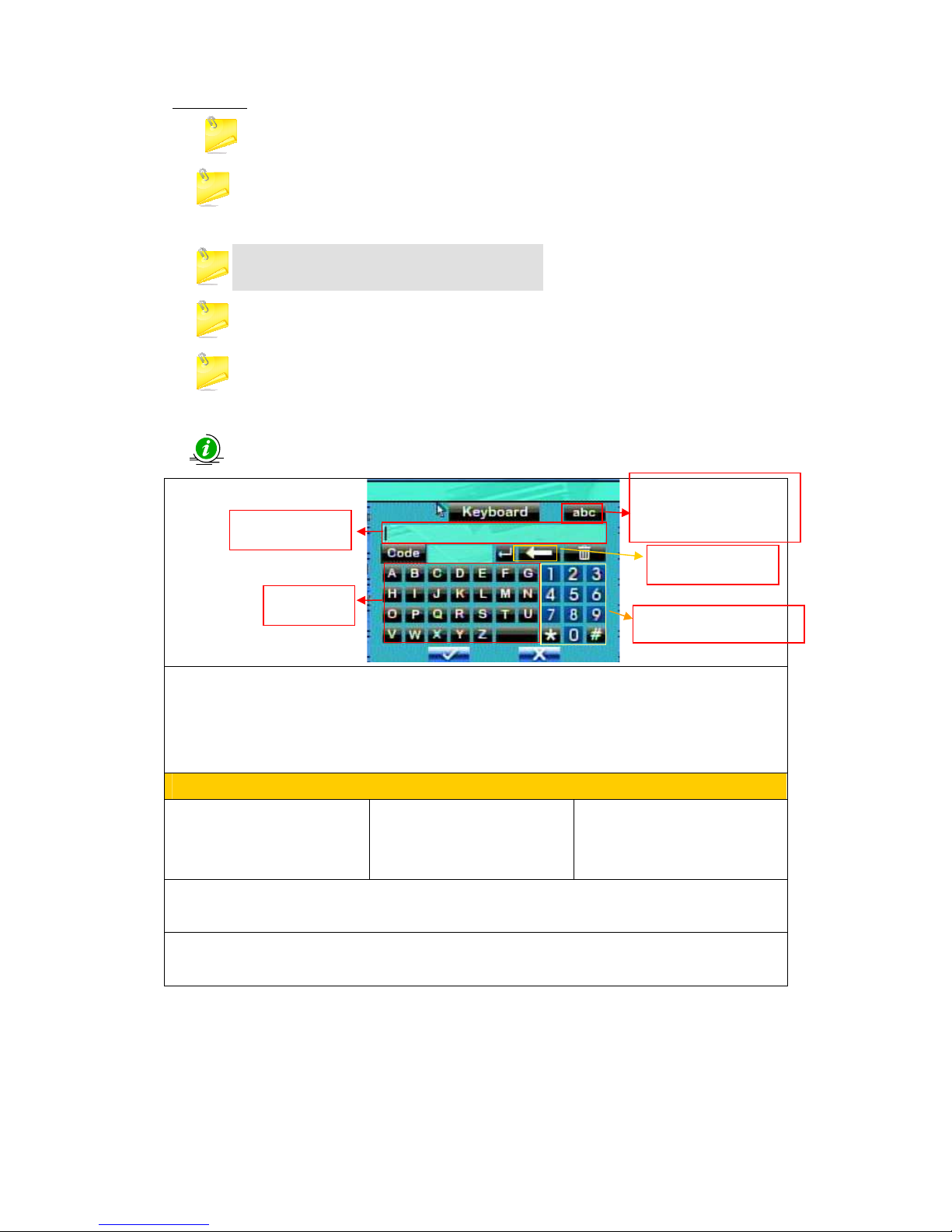
Text Input as below:
In the “abc” button, there’s 3 types of functions:
abc = No capital letters
ABC = All capital letters
Code
For remote control:
Press mark to bring up a list
of punctuation marks and
special characters.
The highlighted character in
the list shows the selected
one.
Press ▲▼◄► button to
change the selection.
If you make a mistake, press BS to remove the character to the left of the cursor, or press DEL
to delete the character at the current cursor position.
In text editing mode press ENTER to exit and save changes, press ESC to exit without making
changes.
Text key
Editing panel
Backspace
Number & Symbol key
For changing text
case(Capital letter)
User Manual
27
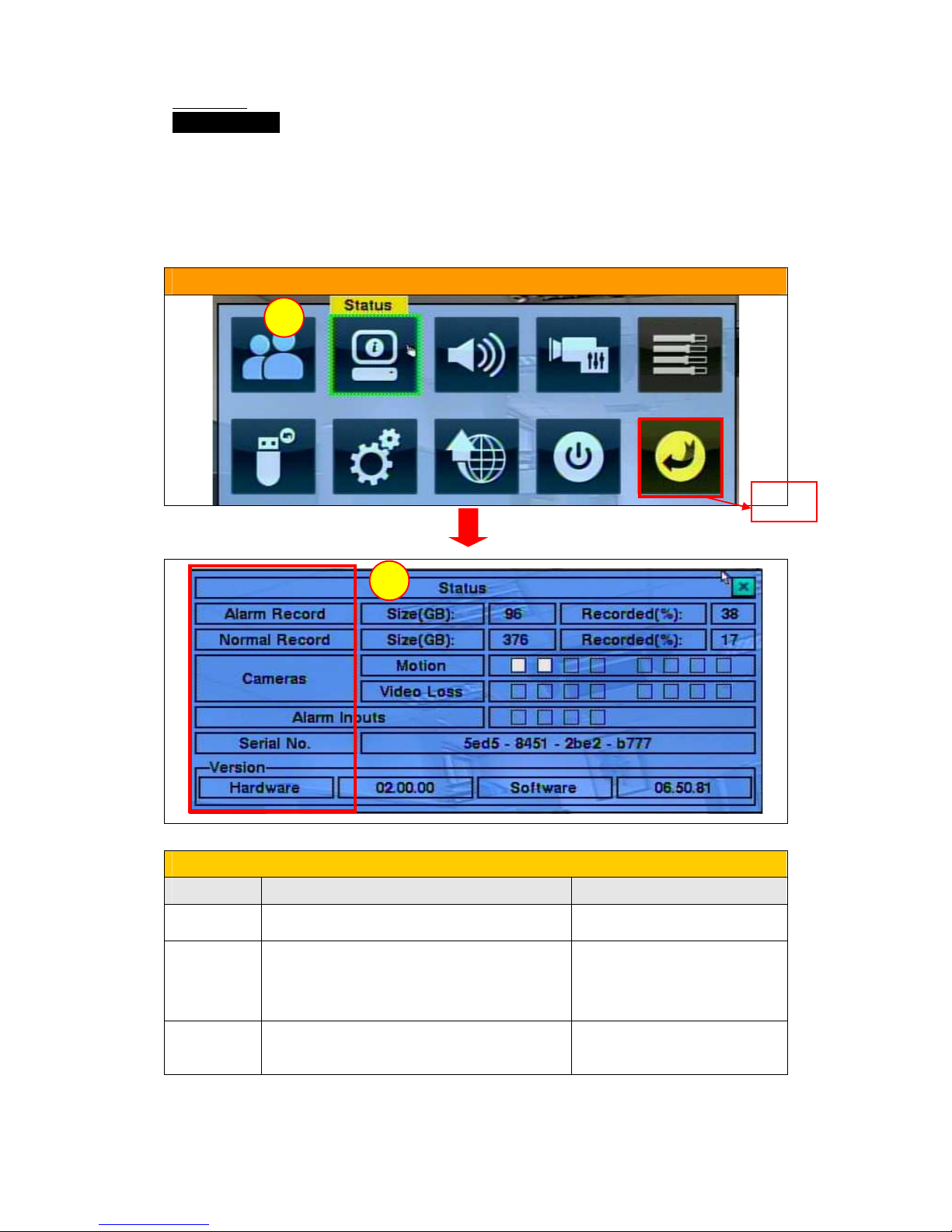
3.1.2. Status:
Description:
This function will display the status of system, including:
Alarm Recording Status, Normal Recording Status, Camera Status,
Alarm Input Status, Product Serial Number as well as Product Version
Number.
OSD DISPLAY MENU(Status)
Checking Procedures
STEPS MOUSE Button/Remote control
STEP 1
Click on ”STATUS” icon.
1.Press “MENU” button.
STEP 2
The “Status” menu will be displayed.
2. Press”▲▼
◄►”
button to
change the highlighted option
and Press “Enter” button.
STEP 3
Right click for EXIT and then click
on ”ESC” Icon for EXIT.
Press “ESC” button for exit.
EXIT
EXITEXIT
EXIT
1
2
User Manual
28
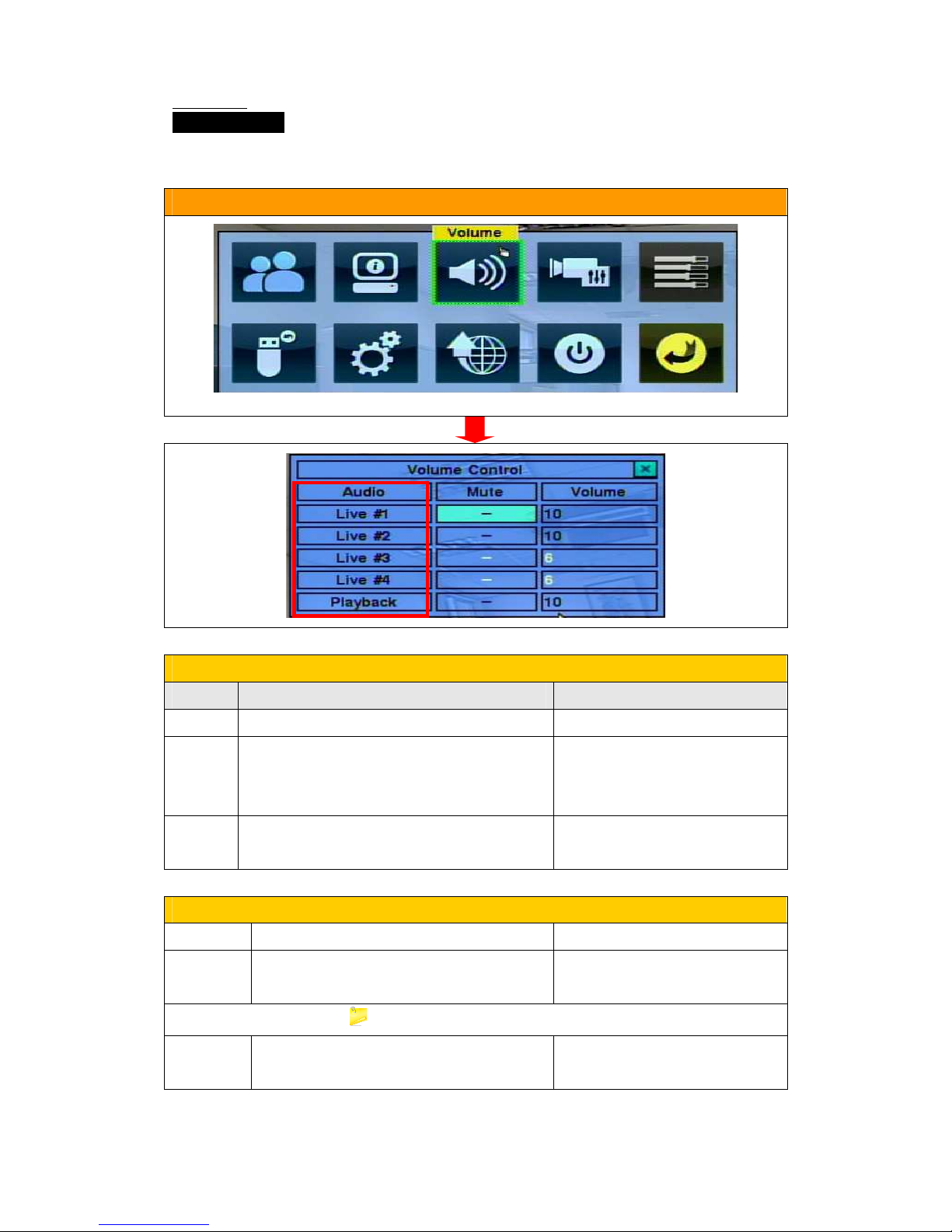
3.1.3 Volume:
Description:
In this function, you can check the live recording volume and playback volume.
OSD DISPLAY MENU(Volume)
Setting Procedures
STEPS MOUSE Button/Remote control
STEP 1 Click on ”Volume” icon. 1.Press “MENU/ESC” button.
STEP 2 The “Volume” menu will be displayed.
And then Click in the respective item.
2. Press”▲▼◄►” button to
change the highlighted option
and Press “Enter” button.
STEP 3 Right click for EXIT and then click on ”ESC”
Icon for EXIT.
Press “MENU/ESC” button for
exit.
Other Functions
Functions
Description Button/Remote control
Mute
To mute the selected audio channel.
Press ”ENTER” button or”+/-“ to
check/uncheck this item.
The default setting is “-”, unchecked.
Volume
The Status menu will be displayed.
Press”+/- “buttons to change the
value (1-10).
User Manual
29
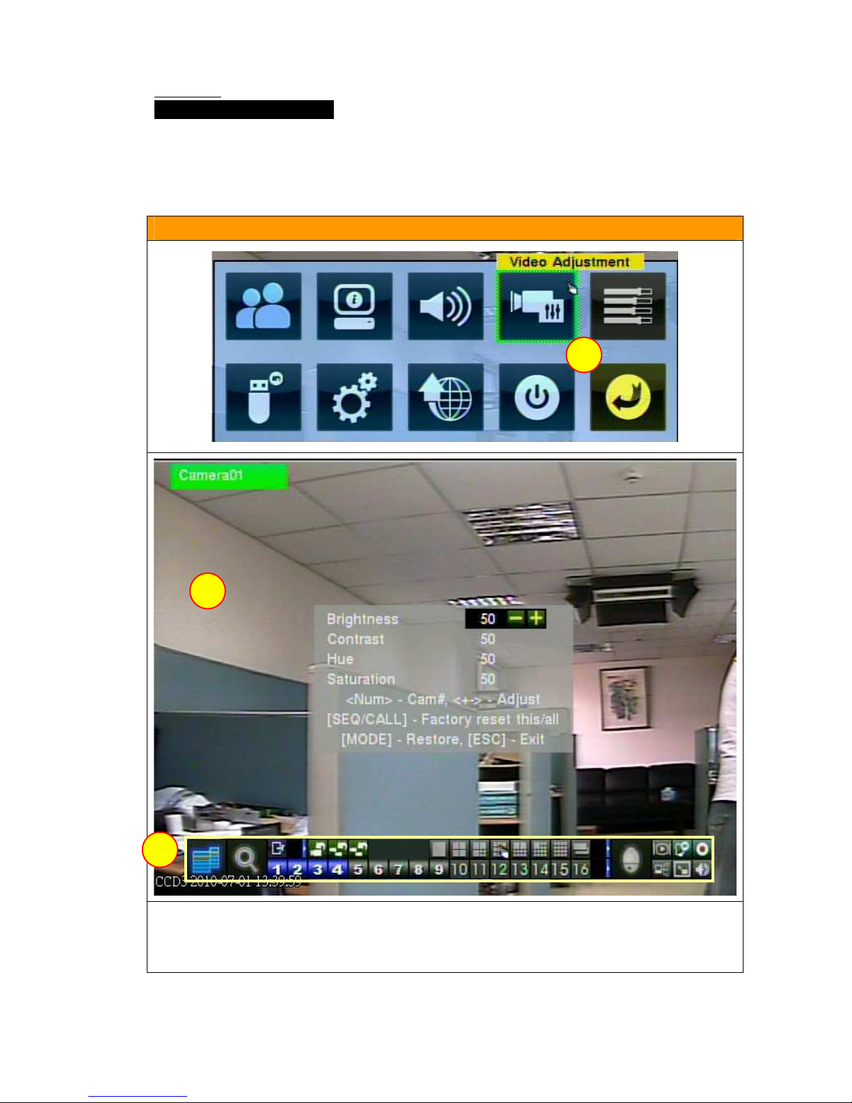
3.1.4. Video adjustment:
Description:
You can adjust the Brightness, Contrast ,Hue and Saturation in this option.
When you enter this option, the basic operation menu will be displayed in
the bottom(3), as below:
OSD DISPLAY MENU(Video adjustment)
1.VIDEO ADJUSTMENT OPTION
2.DISPLAY ADJUSTING TABLE(Brightness/Contrast/Hue/Saturation)
3. BASIC OPERATION MENU
2
1
3
User Manual
30
Setting Procedures
STEPS MOUSE Button/Remote control
STEP 1 Click on ”Video adjustment” icon.
1. Press “MENU” button.
STEP 2 The “Video adjustment” menu will be
displayed, and then select the value for
your needs.
2. Press
▲▼◄►
button to
change the highlighted option
and Press “Enter “button.
STEP 3
Right click for EXIT and then click
on ”ESC” Icon for EXIT.
3.Press “+/-“ to adjust the
selected item.
4. Press” ESC” button for
exit.
The functions of basic operation menu
Picture
Functions
Description
Menu
Press it can return back to OSD Display menu.
SEARCH
For displaying searching menu,
The searching result is memorized
automatically.(Administrator/Supervisor)
Numeric
For selecting camera (Channels).
ESC
EXIT
Factory
reset all
Reset all values back to factory setting.
Factory
reset this
Reset all values back to factory setting.
Restore
Reset all values back to factory setting.
Record
Press it for recording video.
Alarm
Reset
Reset all functions of alarm
 Loading...