

Konig SEC-DVR304 User Manual

Standalone DVR
SEC-DVR304
User’s Manual
Default Account & Password for SEC-DVR304
- User Account: [ aa ]
- Password : [11 ]

2
Standalone DVR SEC-DVR304 User Manual
【【【【Table of Contents】】】】
1 Package Content .................................................................................................... 4
2 Feature .................................................................................................................... 5
3 Specification........................................................................................................... 6
4 Hardware Introduction And Installation ............................................................... 8
4.1 SEC-DVR304 Front view............................................................................... 8
4.2 SEC-DVR304 Back view ............................................................................. 10
4.3 Remote controller ........................................................................................ 11
4.4 Standalone DVR Utility Installation & Manual .............................................. 13
4.5 Basic Connections....................................................................................... 15
4.6 Optional Connections .................................................................................. 17
5 Basic Operation.................................................................................................... 19
5.1 Text Input..................................................................................................... 19
5.2 Basic Operations ......................................................................................... 20
5.3 Digital Zoom ................................................................................................ 22
6 Main Screen.......................................................................................................... 23
7 Menu...................................................................................................................... 24
7.1 Login / Logout.............................................................................................. 25
7.2 Status .......................................................................................................... 26
7.3 Video Adjustment ........................................................................................ 27
7.4 VGA Display ................................................................................................ 28
7.5 Backup Device ............................................................................................ 29
7.5.1 Backup Setting ................................................................................. 30
7.6 Setup........................................................................................................... 33
7.6.1 Pre-Camera ........................................................................................... 35
7.6.2 Camera .................................................................................................. 36
7.6.2.1 Video Loss Setting......................................................................... 38
7.6.2.1 Motion Setting................................................................................ 40
7.6.3 Alarm...................................................................................................... 42
7.6.4 SEQ Display Setup ................................................................................ 44
7.6.5 Scheduled Record ................................................................................. 45
7.6.6 HDD ....................................................................................................... 46
7.6.7 Password ............................................................................................... 52
7.6.8 System Setup......................................................................................... 53
7.6.9 RS-232 / 422 / 485................................................................................. 54
7.6.10 Network................................................................................................ 56
7.6.10.1 Email Setting.............................................................................. 58

3
Standalone DVR SEC-DVR304 User Manual
7.6.10.2 FTP Setting .............................................................................. 59
7.10.3 Advance Network Setting .......................................................... 60
7.7 System Shutdown (Administrator) ............................................................... 61
8 PTZ Control........................................................................................................... 62
9 Software Upgrade ................................................................................................ 68
10 Search & Playback........................................................................................ 69
10.1 Search By Time ........................................................................................... 70
10.2 Search By Event / Log Display .................................................................... 71
10.3 Smart Search .............................................................................................. 72
10.4 Search Archived Files.................................................................................. 74
10.5 Playback/Archive For Search By Time ........................................................ 75
10.6 Playback/Archive For Search By Event....................................................... 78
10.7 Playback/Archive For Smart Search............................................................ 78
10.8 Playback For Archived Files ........................................................................ 79
11 Remote Access ............................................................................................. 80
11.1 Remote Access via Internet Explorer (IE).................................................... 80
11.1.1 Main Screen ..................................................................................... 83
11.1.2 Search & Playback ........................................................................... 85
11.1.3 PTZ Control ...................................................................................... 87
11.1.4 Server Configuration......................................................................... 88
11.2 Remote Access via PDA............................................................................ 104
11.3 IE Remote Access via Vista....................................................................... 107
Appendix A –Time Zone ........................................................................................... 109
Appendix B – Recording Table Reference (PAL) .....................................................111
Appendix C –Standalone DVR access via router setting ...................................... 112
Appendix D – Backup Video File ............................................................................. 115
Appendix E –Frequently Asked Questions & Trouble Shooting ........................... 125
Appendix F - Application Steps: DDNS & Domain Name....................................... 127
4
Standalone DVR SEC-DVR304 User Manual
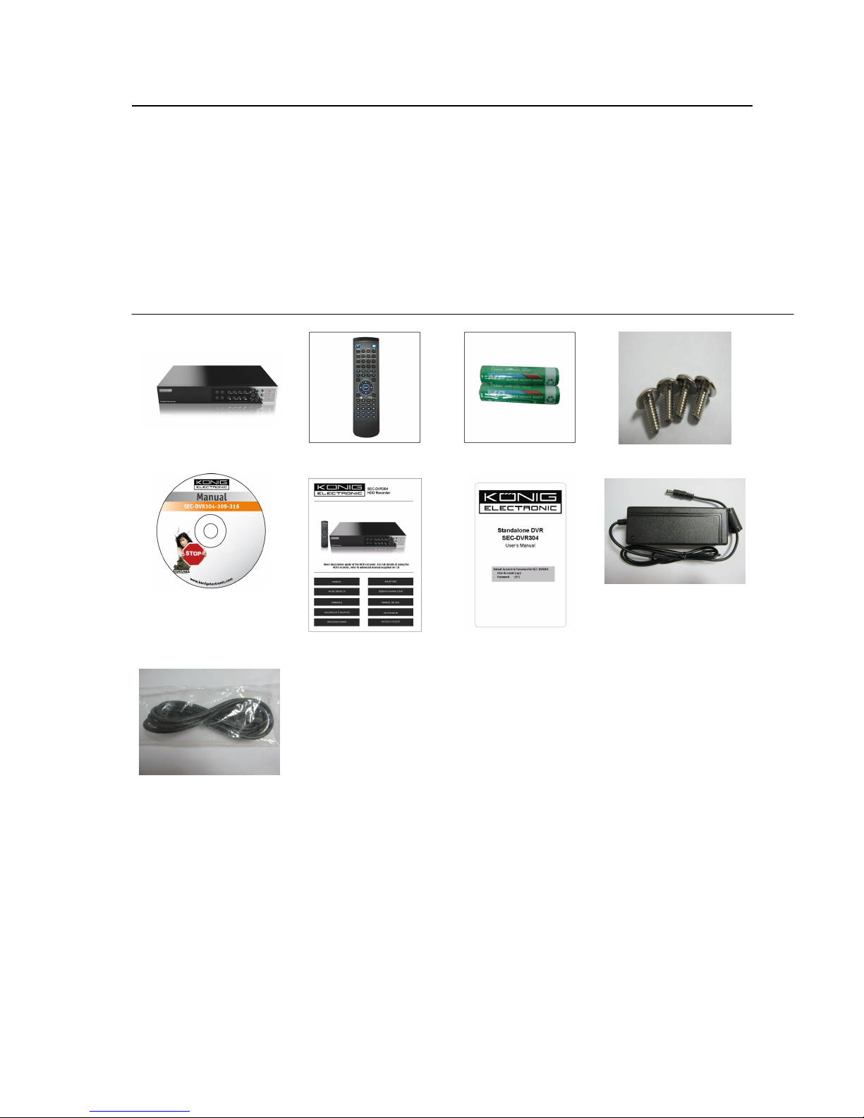
1 Package Content
1-1. SEC-DVR304------------------------------ x1
1-2. Remote Controller ------------------------ x1
1-3. AAA Battery ------------------------------- x2
1-4. Screws ------------------------------------- x4
1-5. CD ------------------------------------------ x1
1-6. Quick Reference--------------------------- x1
1-7. User Manual on CD----------------------- x1
1-8. Power Adapter ---------------------------- x1
1-9. Power Cable ------------------------------- x1
SEC-DVR304 Remote Controller AAA Battery Screws
CD
Power Cable
Quick Reference
User Manual on CD
Power Adapter

5
Standalone DVR SEC-DVR304 User Manual
2 Feature
■ H.264 Compression for better video quality & smaller record size
■ 4CH H.264 DVR with Sixplex operation
(live, record, playback, backup, control, & remote access)
■ Support DDNS
■ Up to D1 resolution
■ Mouse Driven GUI Interface
■ Two-way-Audio communication capabilities
■ Audio Broadcasting facilitates administrator easy to manage multiple DVR through
one IE
■ Simple USB Backup
■ Supported Multi-language
■ External USB DVD-RW & USB HDD supported (Back-UP)
■ Digital Zoom 2X / 4X
■ Smart search: provides smart search of “Mark specific Area” for quicker search
■ Digital Watermark to Prevent film to be altered.
■ Playback search by time or event (alarm, motion, video loss)
■ 1 SATA HDD.
■ USB2.0 * 1 for video/audio backup to versatile USB2.0 storage devices
USB1.1 * 1 for mouse operation
■ Multi-Operation interface: front panel, remote controller and mouse operation
■ RS-485 for PTZ camera
■ Immediately remote trigger I/O devices via IE remote software & Mobile Phone
■ Free Bundle powerful CMS web remote management software, control up to 64chs
on one screen & no limitation for number of DVRs connections.

6
Standalone DVR SEC-DVR304 User Manual
3 Specification
Model SEC-DVR304_4ch
System
Video
Record
Display
Playback
Storage
Alarm &
DI/DO
O.S. Embedded Linux 2.6
Multiplex Sixplex operation - simultaneous record, live, playback,
backup, control, & remote access
Processor Multiple
Certification FCC, CE
Format NTSC/ PAL
Input 4-CH, BNC, 1Vp-p/75ohm
Main monitor BNC x 1, 1Vp-p/75ohm
VGA D-SUB 15-pin connector x1
Call monitor BNC x 1, 1Vp-p/75ohm
Loss detection Yes
Motion detection Yes, with configurable detection area & sensitivity
Input 1 RCA-jack connectors, line-in level (100mV-2Vrms) Audio
Output 1 RCA-jack connector, line-out level (up to 2Vrms)
Compression H.264 compression
Frame rate (IPS) &
Resolution
Watermark Yes
Mode Manual/Schedule/Alarm/Motion
Pre-record time 0 - 60 seconds
Post-record time 0 - 60 minutes
Resolution NTSC: 720*480, PAL: 720*576
Split windows 1/4
Frame rate Up to 30/25 IPS per display window
Digital Zoom X2, X4
Sequential switch User adjustable
Frame rate (IPS) &
Resolution
Search Smart search, Date/time, Camera, Alarm, & Motion
Operation Play, Fast Forward, Backward, Pause, Stop.
Remote Remote playback from IE CMS software or Proprietary
HDD
Partitions Configurable alarm partition size
External Backup 1 USB 2.0 port : USB 2.0 disk drives, DVD+RW, DVD+R,
Digital Input 4 contact or TTL/CMOS signal, polarity selectable
Relay Output NO (Normally Open) x 1, NC (Normally Closed) x 1
Buzzer Yes
Trigger Via Sensor input, Video loss, & Motion
Event log Yes
Ethernet 1 RJ-45 10/100BaseT Ethernet connector Network
Web Remote setup, monitoring, backup, alarm notification, &
NTSC – 30 / 720*480, 60 / 720*240, 120/360*240
PAL – 25 / 720*576, 50 / 720*288, 100 / 360*288
NTSC – 30 / 720*480, 60 / 720*240, 120/360*240
PAL – 25 / 720*576, 50 / 720*288, 100 / 360*288
Player
1 set of 3.5” SATA type HDD,
Max. 1TB HDD storage size
Failure detection & privacy law supported (Record time
limitation adjustable)
Configurable auto-overwrite or not
DVD-R, card readers (USB to SD), HDD, etc.
DVD models: DVD+RW, DVD+R, DVD-R (optional)
Auto player for backup files
remote software upgrade
One I.E. page for unlimited DVRs connection
Configurable HTTP/Control/Data port

7
Standalone DVR SEC-DVR304 User Manual
E-mail Alarm notification to stationary or mobile devices
FTP Alarm video/audio file storage
Video 1/4 split-window & SEQ mode for I.E.
Audio Two way audio and Audio Broadcasting
Protocol TCP/IP, HTTP, PPPoE, DHCP, DDNS, FTP, TSP
Remote users Up to 8 users simultaneously
Bandwidth TCP/IP type dynamic sliding window control
Remote stations PC, mobile phone, or PDA
I/R 1 I/R remote controller Control
RS-485
Interface
Setup
System
Weights &
Dimension
Operating Temperature 0oC ~ +50oC
PTZ Pelco (D-Type), SCC-641P, PIH-Series, DyanColor,
Kalatel, Bosch AutoDome, Video Trek, PTC-400C,
VC-C4
Local On screen setup via mouse, keypad (Key of front panel),
I/R remote controller, and/or RS-485 keyboard
Remote Setup & upload via Windows application software
Multi-language Yes
System recovery Auto power on after power loss recovery
Watch Dog Timer Yes
Timer Built-in real time clock
Security Muli-level password (3 levels, up to 18 accounts)
protection with authentication key for remote access
Dimension
Weight
Source +12VDC Power
Consumption 24W Max.
320(W) x 210(D) x 50(H)mm
2.0 KG (without HDD)
8
Standalone DVR SEC-DVR304 User Manual
4 Hardware Introduction And Installation
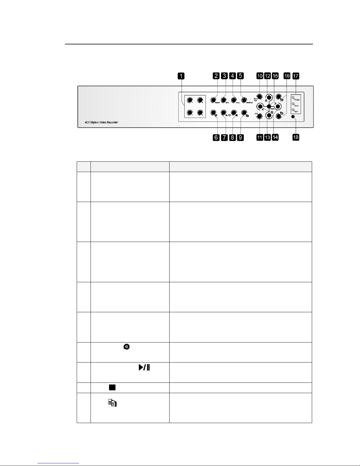
4.1 SEC-DVR304 Front view
Name Description
1 Alpha-numeric Buttons (1-4)
2 MODE Button
3 SEQ Button Press this button to switch to or return from SEQ display mode
4 CALL Button
5 SEARCH Button Press this button to display the search menu in main
Press these buttons for camera selection in most of the
circumstances. These buttons can also be used to enter text
and number in the way similar to most of the mobile phones.
Press this button to toggle between live mode and playback
mode in main screen display. In some dialogs, this button is
used as a miscellaneous function key. At playing, this button
is used as “slow backward”.
in main screen display. In some dialogs, this button is used
as a miscellaneous function key. At playing, this button is
used as “slow forward”.
Press this button to switch to or return from full screen display
of the focus camera in main screen display. In some dialogs,
this button is used as a miscellaneous function key.
screen display. In some dialogs, this button is used as a
miscellaneous function key.
6
REC Button ( )
7
Play/Pause Button ( )
8
Stop ( ) Button
9
Copy( ) Button
Press this button to force manual recording. To stop
manual recording, press it again.
Press this button to play the recorded images, or pause
the playback.
Press this button to stop the playback.
Press this button to copy the playback images to the
storage device connected to the USB port. Press this
button again to stop copying.

9
Standalone DVR SEC-DVR304 User Manual
10 MENU / ESC Button
Press this button to display the main menu or escape to
the upper level display.
11 PTZ Button
12 Up/BS Button (▲/BS)
13 Down/DEL Button (▼/DEL)
14 Left/Right Buttons (◄,►)
15 ENTER Button
In main screen display, press this button to enter/exit PTZ
control if the focus camera is a PTZ camera.
Press this button to move the cursor or focus window in
most circumstances. In PTZ control, press this button to
tilt up the camera. In text editing mode, this button is
used as “backspace” key.
Press this button to move the cursor or focus window in
most circumstances. In PTZ control, press this button to
tilt down the camera. In text editing mode, this button is
used as “del” key. In playback mode, press this button
for single step.
In PTZ control, press these buttons to pan the camera.
In playback mode, press these buttons for fast
backward/forward. In the other screens, press these
buttons to move the cursor or focus window.
This button is used as “enter” key in most circumstances. In
PTZ control, this button is used to start/stop the selected PTZ
control mode.
16
(Split Windows) +/- Buttons ( )
17 LEDs Indicators for POWER, HDD and Network access.
18 Remote I/R Sensor Used to receive signal from I/R remote controller.
In split-window display, press these buttons for next/previous
split-window display. In the others, press these buttons to
change the contents.
10
485 compatible devices for the correct settings.
Standalone DVR SEC-DVR304 User Manual
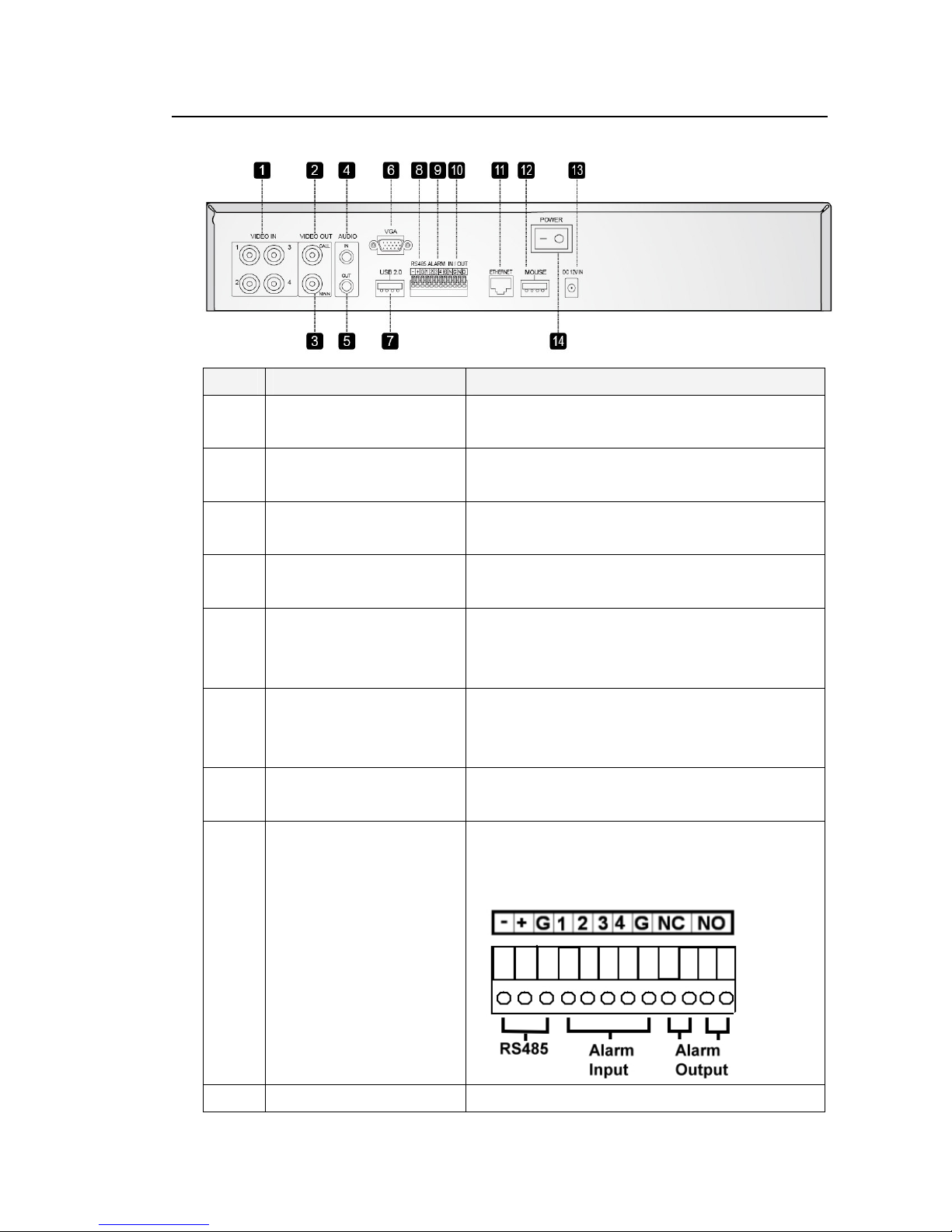
4.2 SEC-DVR304 Back view
Name Description
1 Video Input Connectors (1-4) Connect system cameras to these BNC connectors. The
internal 75Ω termination is always ON.
2 Call Monitor Output Connector
(CALL OUT)
3 Main Monitor Output
Connectors (MAIN OUT)
4 Audio Input Connectors
(AUDIO IN)
5 Audio Output Connectors
(AUDIO OUT)
6 Main Monitor Output VGA
Connector (MAIN OUT VGA,
optional)
7 USB2.0 Connector Connect to USB 2.0 compatible storage device, such as
8 RS-485 Connector Connect this connector to RS-485 compatible PTZ
Connect TV monitor to this BNC connector for call monitor
display.
Connect TV monitors to the BNC connector for main
monitor display.
The RCA connector accepts line-in audio signal supplied
from external devices such as microphone amplifiers.
The connector supplies line-out audio signal to external
devices such as speakers. Recorded audio will be
supplied from AUDIO OUT during playback.
Connect VGA monitor to the optional D-SUB 15-pin female
connector for main monitor display.
USB 2.0 disk drive, DVD+RW, card reader, etc.
camera(s) or keyboard. Please refer to the manuals come
with the RS-
9 Alarm Input Connectors Connect these connectors to external devices such as
11
Standalone DVR SEC-DVR304 User Manual
(ALARM IN 1-4) sensors or door switches.
10 Alarm Output Connectors
(ALARM OUT NC(1)/NO(2))
11 Ethernet Connector Connect this unit to a 10/100Base-T Ethernet network
12 USB Mouse Connector Connect to USB1.1 mouse before the DVR is power on.
13 Power Cord Inlet (DC 12V) Connect to DC 12V power source.
14 Power Switch (POWER) Turn the power of this unit on/off.
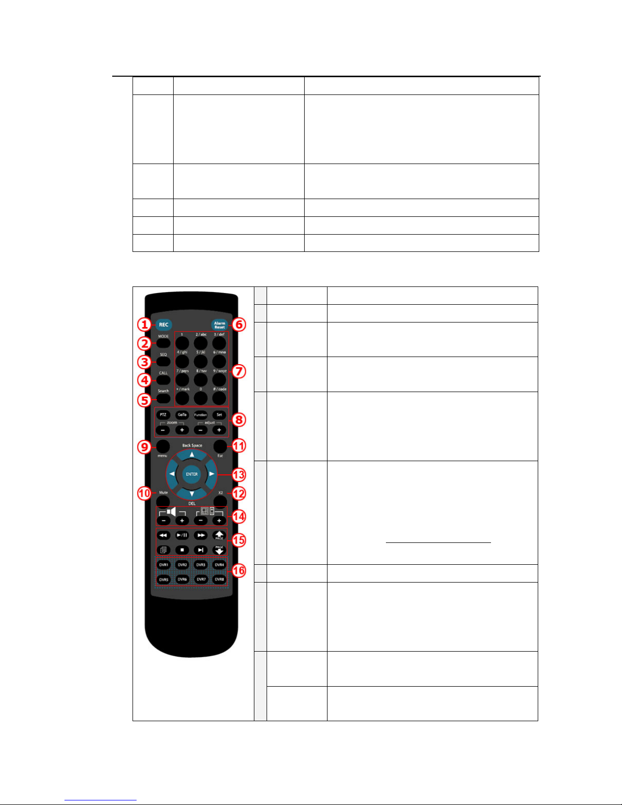
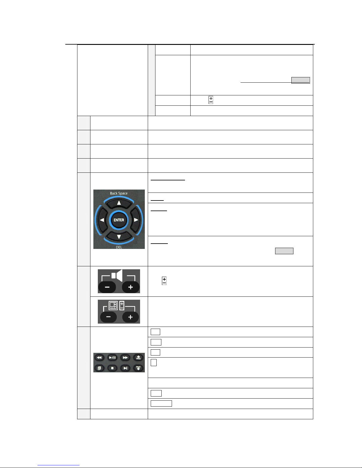
4.3 Remote controller
Connect NC connectors (left) to Normally Closed (NC)
alarm output, or NO connectors (right) to Normally Open
(NO) alarm output. Please note that only one of the NC or
NO connectors can be connected only.
through this port.
Name Description
1 REC Press to start the recording.
Mode Press to switch between live and playback mode.
2
At playing, this button is used as “slow backward”.
SEQ Press to turn on the sequence mode. At playing,
3
this button is used as “slow forward”.
CALL Press this button to switch to or return from full
4
Search Click to search recorded data while in the playback
5
6 Alarm Reset Press to restore the alarm status to default.
Numeric/
alpha button
7
(1-9, 0, *, #)
PTZ Click to access the PTZ control when there is a PTZ
8
Goto Click to view the image taken by PTZ camera at its
screen display of the focus camera in main screen
display. In some dialogs, this button is used as a
miscellaneous function key.
mode. There are five types of search modes: search
by time, search by event, smart search, search
archived files and POS search.
(Please refer to Chapter 10 Search & Playback for detail
information.)
Press these buttons for camera selection in most of
the circumstances. Use these buttons to enter texts
and numerical values. ’#’ is also used for page
down in multi-split-window displays.
camera supported.
preset location.
12
Standalone DVR SEC-DVR304 User Manual
Function Click to add an audio recording feature.
Set Click to switch between GPS (POS: option) Display
and to reconfigure the display setting.
(Please refer to Chapter 7.6.9 RS-232 / 422 / 485NOTE 2
for detail setup)
10
11
12
13
Zoom
Adjust Click to switch between different display layouts.
9
Menu Press to access the menu dialog box.
Mute Press to either mute or un-mute audio.
Esc Press to exit the setting page.
X2 Press to adjust the zoom.
▲/Back Space: Click to move up the selection panel or backspace
◄; ►: Click to move left or right.
▼/DEL: Click to move down the selection panel or delete text during
text/numeric entry.
ENTER: Click to enter a feature setting/GPS & POS setting and to save
changes. (Please refer to Chapter 7.6.9 RS-232 / 422 / 485 NOTE 2 for
detail information on GPS/POS setting)
Press to adjust the zoom of the camera.
during text/numeric entry.
14
15
16 DVR1 – DVR8
Use to adjust the volume.
Click to switch between different screen layouts.
: Rewind feature.
/ II: Click to play or pause the playback.
: Forward feature.
: Click to copy an image to an external storage device. Click again to
stop copying.
: Stop the playback.
I : Click to skip to the next image.
Page: Press to scroll up/down the log list.
Reserve.
13
Standalone DVR SEC-DVR304 User Manual
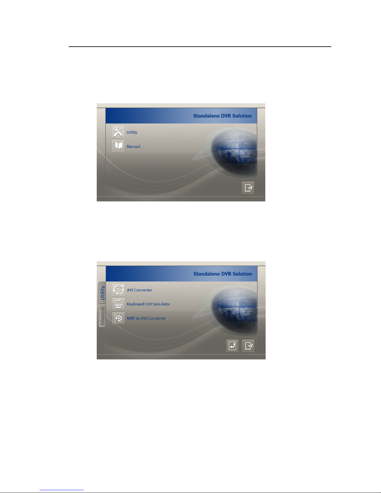
4.4 Standalone DVR Utility Installation & Manual
4.4.1 Utility Installation
Insert the Installation CD into the CD-ROM.
Execute ‘’Autorun.exe’’. Next Click on ‘’Utility’’ button.
* AVI Converter can convert the backup file from Standalone into AVI file.
* Keyboard Ctrl Simulator can use to simulate a keyboard to control over Standalone
DVR.
* M4V to AVI Converter.
14
Standalone DVR SEC-DVR304 User Manual
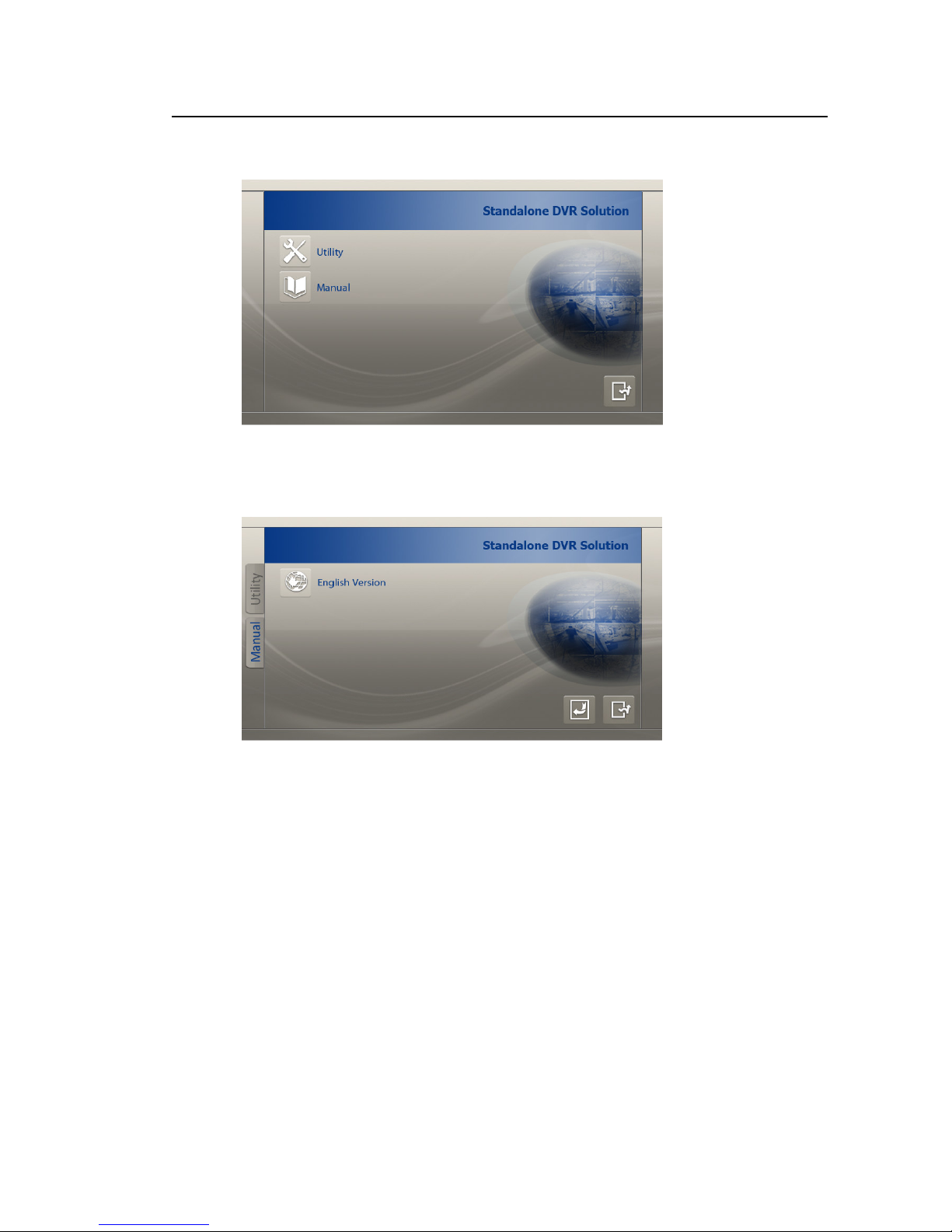
4.4.2 Manual
Click on ’’Manual’’ button.
Click on ‘’English Version‘’ button to view English Manual.
15
Standalone DVR SEC-DVR304 User Manual
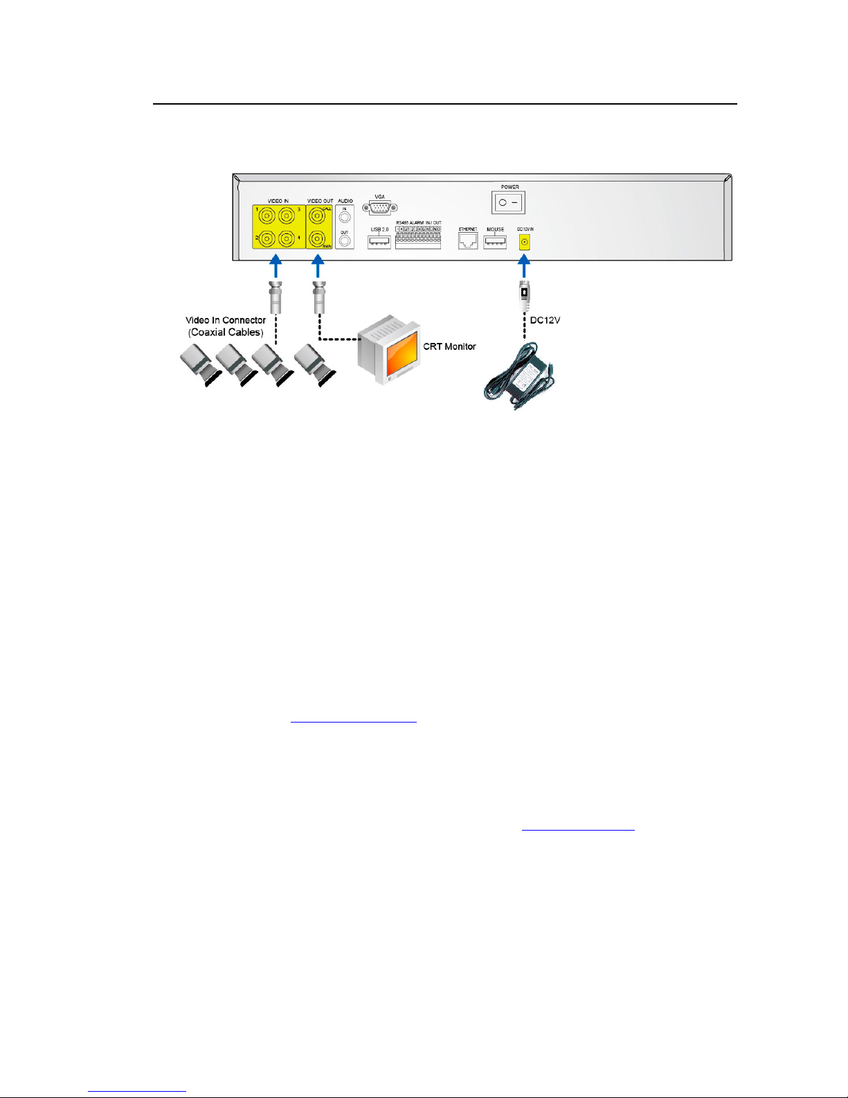
4.5 Basic Connections
Please refer to the following diagram for the connections.
Please make sure to set the NTSC/PAL Selector Switch on the main board according to the
local TV system for the system to work correctly.
Cameras
Connect the camera video input connectors to the video outputs from system cameras or
other composite video sources via coaxial cables. The internal 75Ω termination is always
ON.
Main monitor
Connect the main monitor output connector (BNC) to a surveillance TV monitor, or connect
the optional VGA output connector to a VGA monitor. The TV/VGA monitor displays
selected live or recorded cameras in any available split window format.
Audio inputs
Connect the audio input connectors to the audio line-outs from system cameras or other audio
sources. Please make sure to associate the audio inputs with the cameras in Camera Setup
as described in Section 7.6.2 Camera accordingly.
Audio output
Connect the audio output connector to the audio line-in from speakers.
Alarm inputs
Connect the alarm inputs to NC and/or NO type of alarm signals. Please make sure to setup
the alarm configurations in Alarm Setup as described in Section 7.6.3 Alarm accordingly.
Alarm outputs
Connect the alarm outputs 1-2 to NC type of alarm signals, alarm outputs 3-4 to NO type of
alarm signals.

16
Standalone DVR SEC-DVR304 User Manual
Hard disk drive
Make sure to install at least one SATA hard disk drive inside the DVR. The steps are as
below:
1. Power off the machine, and then use a screwdriver to uncover it
2. Connect the cables as shown
3. Hold the SATA HDD, and use a screwdriver to fix it as shown
4. Cover the machine
Note: Each of the HDD must be formatted before it can be used to record video/audio.
Please refer to Section 7.6.6.1 HDD Format/Clear to format the HDD.
17
Standalone DVR SEC-DVR304 User Manual
Power
Connect DC 12V power source to DC 12V Input.
I/R remote controller
The user may use I/R remote controller to control the digital video/audio recorder.
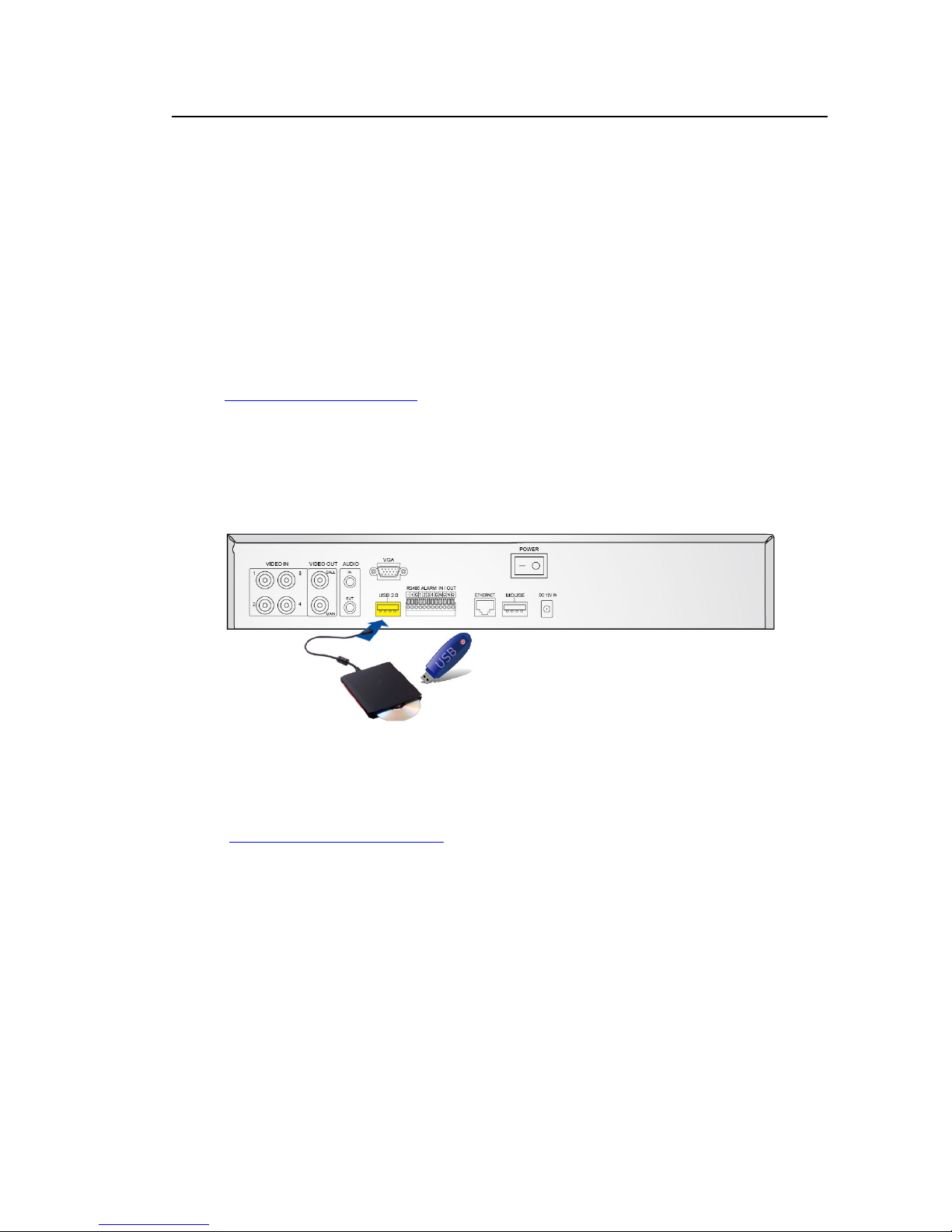
4.6 Optional Connections
Ethernet
Connect the Ethernet connector to a standard twisted-pair Ethernet cable for remote access
via LAN or internet. Please make sure to setup the related configurations as described in
Section 7.6.10 Network Setup.
USB 2.0 disk drives, DVD+RW, card reader, etc.
If the user wants to use USB2.0 peripheral device to retrieve important recorded images
and/or audio, please connect it to the USB port connectors (one on the front panel, the other
on the back panel).
Call monitor
Connect the call monitor output connector to a surveillance TV monitor. This monitor
displays the full screen images of the cameras associated with the events (alarm or motion) or
the images from the installed cameras sequentially according to the SEQ Display Setup
(Section 7.6.4 SEQ Display Setup) for call monitor.
18
Standalone DVR SEC-DVR304 User Manual
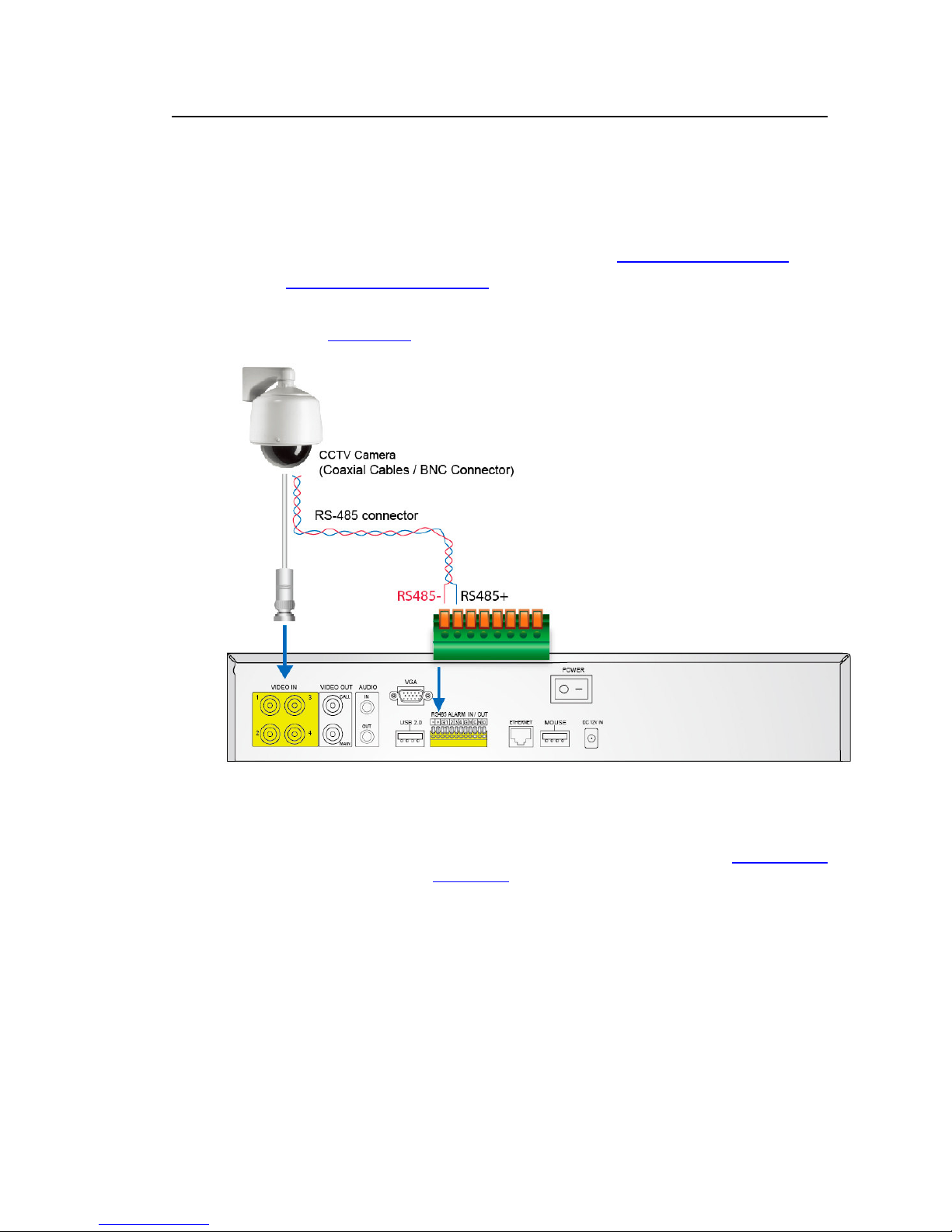
PTZ Cameras
Connect the RS-232 connector or the RS-485 connector to PTZ camera(s) via the appropriate
cable. The system supports a variety of different PTZ cameras, including Pelco D protocol
Dome, SamSung SCC-641P, Kalatel Cyber Dome, Bosch AutoDome, etc. But different PTZ
cameras can coexist in a system only if they support the same protocol. Please make sure
to set the PTZ ID of the camera(s), and setup the camera (Section 7.6.1 Pre-Camera), and
RS-485 (Section 7.6.9 RS-232/422/485) accordingly. Please also make sure to set the
RS-485 Selector Switch if you are using the RS-485 port.
(Please refer to Chap 8. PTZ Control for detail information)
RS-485 keyboard or Terminal
Connect the RS-485 connector to a RS-485 keyboard controller via the appropriate cables.
Please make sure to setup the RS-422/485 configurations as described in Section 7.6.9
accordingly. Please refer to Appendix B for the Keyboard Control Protocol for the digital
video recorder.

19
2 3 4 5
B A 9 8 7
Standalone DVR SEC-DVR304 User Manual
5 Basic Operation
5.1 Text Input
Press ▲▼◄► to highlight the text to be edited then press Enter to call up the alpha-numeric text
pad.
1
6
C
Name Description
1
2
1 Press to enter the available number.
3 Press to enter the available number and letter shown on the screen.
3 */Mark Press to bring up a list of punctuation and special symbols.
4
►
5
Press to enter the available number and letters shown on the screen.
Press to enter the available number and letters shown on the screen.
6 CALL Press to enter the available number and letters shown on the screen.
NOTE: Call monitor button is not functional during text/numeric entry.
7
8
9
2 Press to enter the available number and letters shown on the screen.
4 Press to enter the available number and letters shown on the screen.
# Press to enter the code for the selected foreign languages.
A MUTE Press to enter the available number and letters shown on the screen.
NOTE: Mute button is not functional during text/numeric entry.
B
X2 Press to enter the available number and letters shown on the screen.
NOTE: Zoom button is not functional during text/numeric entry.
C SEQ Press to enter number.
NOTE: Sequence mode is not functional during text/numeric entry.
Attention:
For text and numeric entry using the controller, press directly from the
alpha-numeric buttons.

20
Standalone DVR SEC-DVR304 User Manual
5.2 Basic Operations
The basic user’s operations after he/she has logged into the system are described below:
Numeric (Mouse: )
Press these buttons to switch to the full-window display for the camera. If the camera
already exists in the other window, the focus window will exchange with that window for
the cameras.
Alarm Reset (Mouse: )
Press this button to cancel alarm activation, i.e. reset the alarm outputs and silence the
buzzer.
MODE (Mouse: ) (Operate by Administrator/Supervisor)
In split-window display, press this button to change circularly the live/playback mode for the
focus window and the other windows that form a rectangle on the screen.
SEQ (Mouse: )
Press this button to switch to or return from SEQ display mode. In SEQ display mode, each
page in the sequence will be shown for the preset page dwelling time sequentially, and SEQ
icon will be shown on the lower-right corner of the screen.
SEARCH (Mouse: ) (Operate by Administrator/Supervisor)
In split-window display, press this button (or ) to display the search menus. The system
will remember the last one the user chose.
REC (Mouse: )
Press this button to force manual recording. To stop manual recording, press it again. All
cameras will be recorded as if the scheduled record is A/V, and REC icon will be shown on the
lower-right corner of the screen if manual recording is ON.

21
Standalone DVR SEC-DVR304 User Manual
MENU (Mouse: )
In split-window display, press this button to display the versatile menu.
PTZ (Mouse: )
In split-window display, press this button to enter PTZ control mode if the focus camera is a
PTZ camera.
X2 (Mouse: )
In full screen display, press this button to enter Digital Zoom mode. Please refer to Chapter
5.3 Digital Zoom for the detailed operations in Digital Zoom mode.
▲▼◄►
Press these buttons to move focus. The title of the camera for the focus window is
highlighted as shown on the screen.
MUTE (Mouse: )
Press this button to mute/not mute the audio.
(Mouse: )
Press these buttons to circulate up/down among the available split-window displays.
#
Press this button for page down in multi-split-window displays.
Peripherals (Mouse: )
Press this button to display the GPS data if there’s GPS data fed to the DVR. Please select
the Type, Position, Background, Rows, and number of Characters on the screen, and then
press ENTER to display the GPS data, or ESC to cancel. For software V6.13 or above, the
user may enable/disable OSD display for certain fields in main screen. In GPS display,
press ▲▼ for page up/down, press ENTER to close it, or press MENU/SEARCH/.. to call up
the corresponding display as if there’s no GPS display. (※ Note: POS not supported)
22
Standalone DVR SEC-DVR304 User Manual
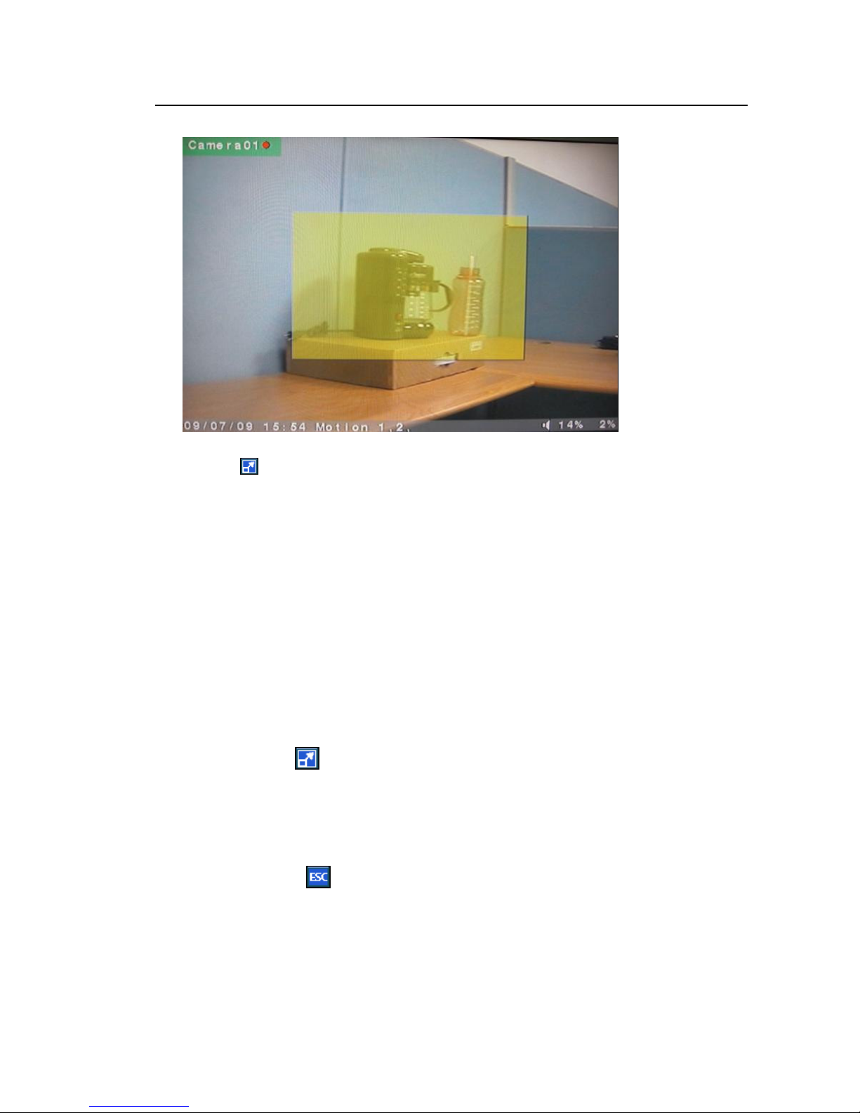
5.3 Digital Zoom
The system supports X2/X4 Digital Zoom function. To use this function, press X2 button
(Mouse: ) in full screen display to enter Digital Zoom mode. There will be a zoom window
shown in the video window as shown. The zoom window (a) will always be shown at zoom
factor X1, (b) can be shown or hidden at zoom factor X2, and (c) will never be shown at zoom
factor X4. The operations in Digital Zoom mode are as below:
▲▼◄► (Mouse: Click in the video window)
Press these buttons to
(a) move the zoom window if it’s shown in the video window, or
(b) navigate the video window around if the zoom factor is X2 or X4.
ENTER (Mouse: Click in the video window)
Press this button to zoom in the zoom window, from X1 to X2 or from X2 to X4, if the zoom
window is shown in the video window.
X2 (Mouse: )
Press this button to
(a) show/hide the zoom window if the current zoom factor is X1/X2, or
(b) zoom out the video window back to zoom factor X1 if the current zoom factor is X4.
ESC (Mouse: )
Press this button to escape from Digital Zoom mode, and return to normal full screen
display. The video window will always return to zoom factor X1.
23
1
2
3
4 5 6
Standalone DVR SEC-DVR304 User Manual
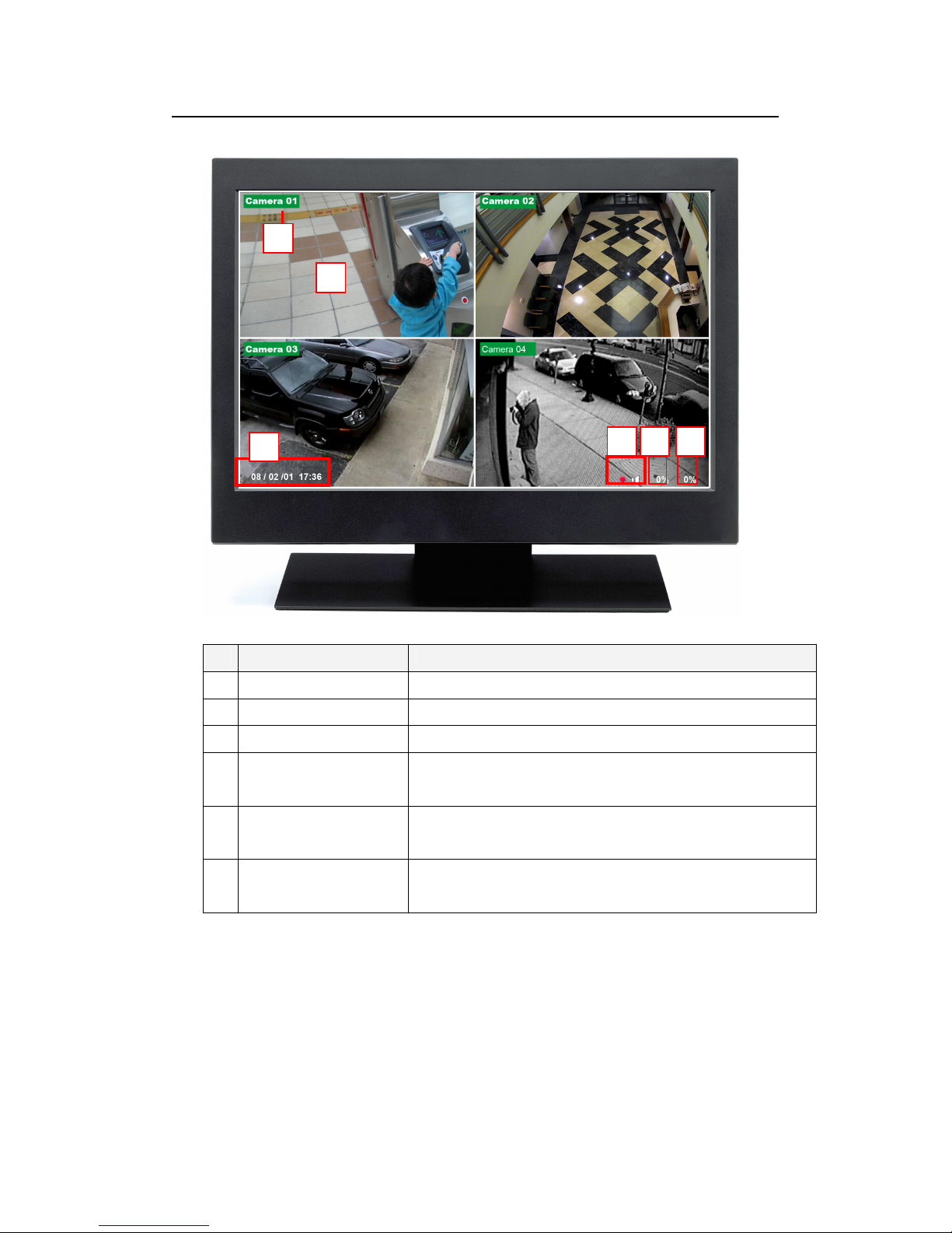
6 Main Screen
Name Description
1 Video Screen Display live/playback video.
2 Camera ID Shows ID number of the camera.
3 Time / Date Shows the current recording time and date.
4 Audio When audio is turned on, audio icon will be displayed on
the screen.
5 Alarm recording
Shows the percentage of alarm triggered recording.
percentage
6 Normal recording
Shows the percentage of normal recording.
percentage
24
Standalone DVR SEC-DVR304 User Manual
7 Menu
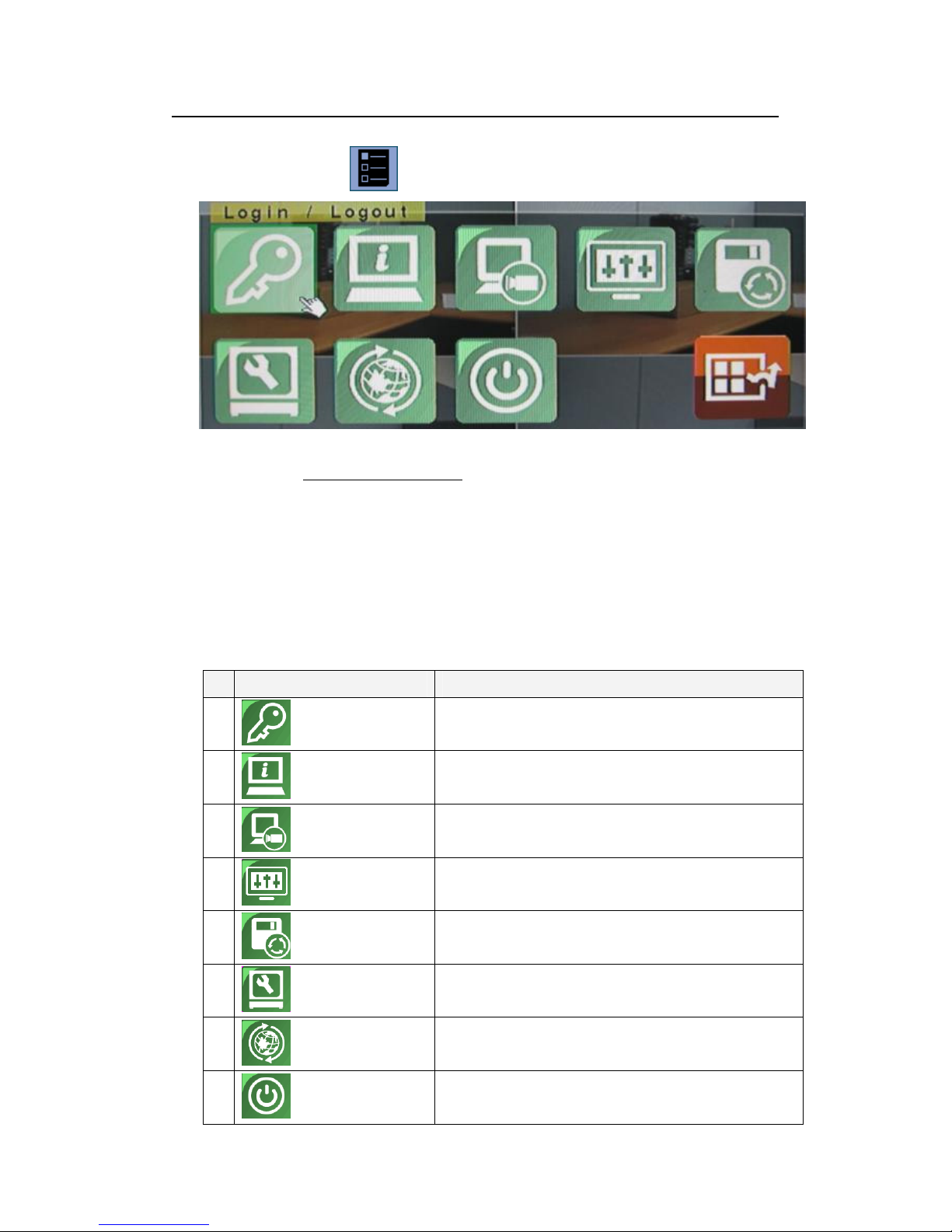
Press menu (Mouse: ) to bring up a list of function setting menu.
There are a variety of displays under Menu display. Please refer to chart as below:
(Please refer to Chapter 7.1 Login / Logout for Login/Logout display. )
▲▼◄►
Press these buttons to change the highlighted item.
ENTER
Press this button to enter the detailed display of the highlighted option. For the
details of each option, please refer to the following sections.
Name Description
1
Login/Logout
2
Status
3
Video Adjustment
4
VGA Display
5
Backup Device
6
Setup
7
Software Upgrade
8
Shutdown
Press to login/logout of the system.
Allow user to view the overall status of the system.
User can adjust the color, hue, saturation, contrast of the
video image.
User can adjust the image output quality in terms of
resolution, brightness, contrast, hue and saturation.
This window allows user to view the connection status of the
backup device and to initiate data backup.
System features settings.
(Please refer to section 7.6 for detail information)
This feature allows user to upgrade the software directly from
the external devices such as DVD and USB flash drive.
Allows users to shutdown the system to prevent data loss.
25
Standalone DVR SEC-DVR304 User Manual
9
ESC
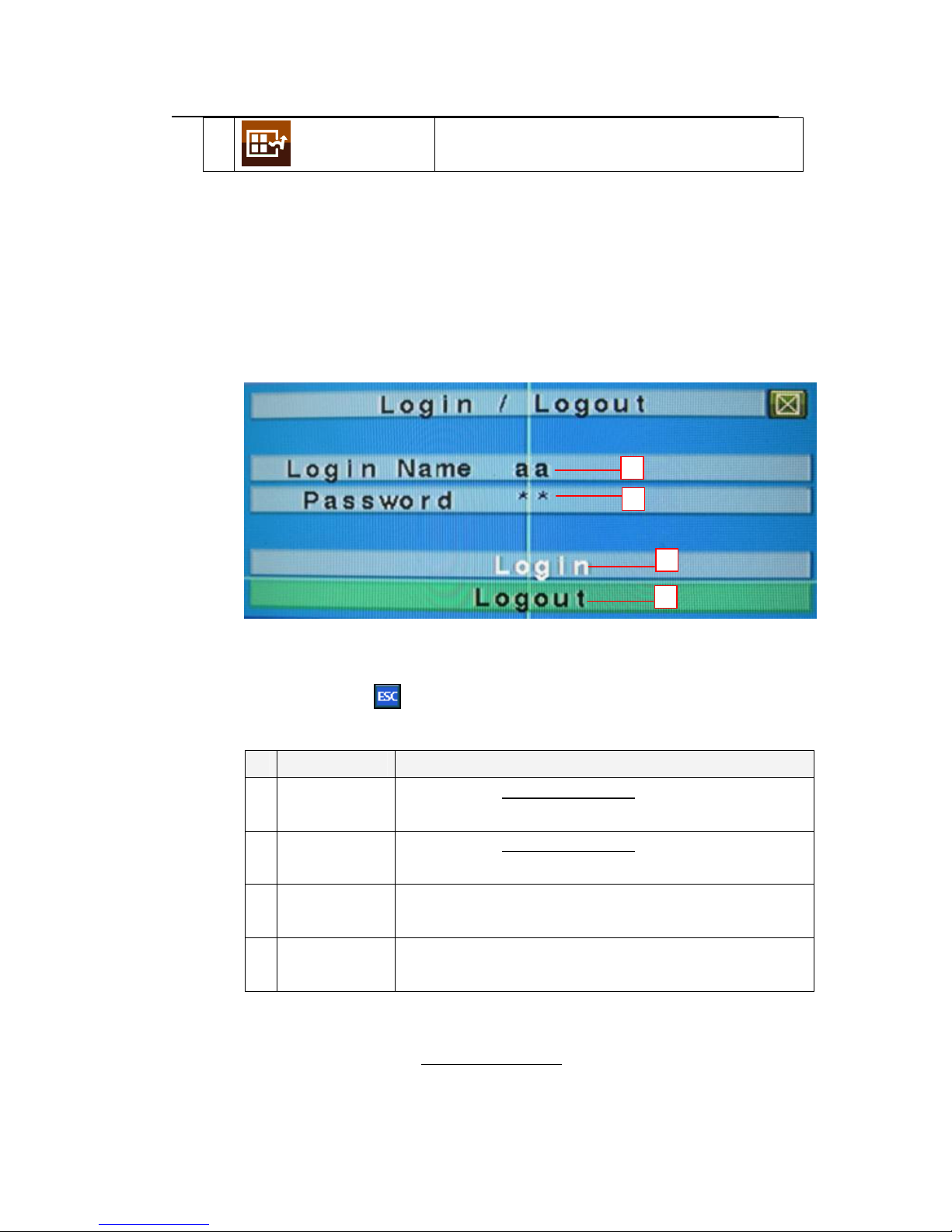
7.1 Login / Logout
In Menu display, press ▲▼ to change the highlighted option to Login / Logout,
and then press ENTER (Mouse: Click in the menu item) to call up Login /
Logout display as shown below.
Click on the Login/Logout page to login the system and unlock the setting for
changes.
Press this button to escape from Menu display, and return to
split-window display.
1
2
3
4
▲▼
Press these buttons to select the items.
ESC (Mouse: )
Press this button to exit without making changes.
Name Description
1 Login Name
Please refer to chapter 5.1 Text Input for text/numeric entry.
Note: The default login name is aa.
2 Password
Please refer to chapter 5.1 Text Input for text/numeric entry.
Note: The default password is 11.
3 Login Click to login into the system.
Note: The control buttons will be unlocked after system login.
4 Logout Click to logout of the system.
Note: The control buttons will be locked after system logout.
NOTE:
Administrator can set access authorities, edit and assign usernames and passwords to
different users. Please refer to Chapter 7.6.7 Password for detail setup.
26
Standalone DVR SEC-DVR304 User Manual
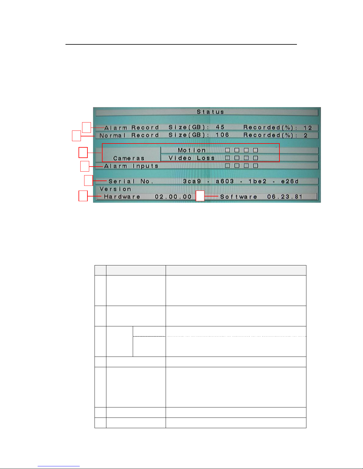
7.2 Status
In Menu display, press ▲▼ to change the highlighted option to Status, and then
press ENTER to call up Status display as shown below.
This page will display the status of the system in terms of alarm and normal record
size, camera status, hardware and software version.
1
2
3
4
6
5
▲▼◄►
Press these buttons to select the items.
ESC
Press this button to escape from this screen, and return to MENU display.
Name Description
1 Alarm record size &
record percentage
2 Normal record size &
record percentage
7
- It shows the size of data in Gigabytes (GB) for alarm
recording mode.
- It shows the size of data (%) for alarm recording mode.
- It shows the size of data (GB) for normal recording mode.
- It shows the size of data (%) for normal recording mode.
3 Cameras
4 Alarm input A white box appears when an alarm triggered event occurs.
5 Serial Number Use serial number to log into the system when both login
6 Hardware version This is the hardware version information.
7 Software version This is the software version information.
Motion A white box for a specific camera appears upon motion trigger.
Camera
video loss
A white box for a specific camera appears when the video
connection is lost.
name and password are forgotten.
Note: The serial number can only be used once. Please contact the
supplier for a new serial number.
27
7
Standalone DVR SEC-DVR304 User Manual
NOTE: If you forget Login Account and Password of SEC-DVR304, please mail the
data of framed area 5,6,7 (Serial Number, Hardware & Software version) to Nedis
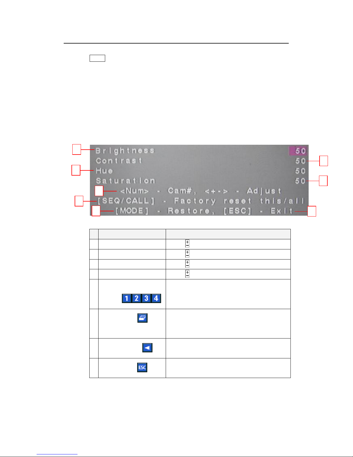
7.3 Video Adjustment
In Menu display, press ▲▼ to change the highlighted option to Video Adjustment,
and then press ENTER to call up Video Adjustment display as shown below.
This setting allows user to adjust the quality of the video.
1
3
5
2
4
6
▲▼ Press these buttons to select the items.
Name Description
1 Brightness
2 Contrast
3 Hue
4 Saturation
5 Numeric Button
(Mouse: )
6
SEQ (Mouse: )
/CALL
7
MODE (Mouse: )
8
ESC (Mouse: )
Press to adjust the Brightness.
Press to adjust the Contrast.
Press to adjust the Hue.
Press to adjust the Saturation.
Press the numeric buttons 1~4 to view the image
of the respected camera.
Click to apply the default video setting either to
this camera or to all cameras.
Click to restore the video setting to its previously
saved setting.
Click this button to escape from this screen, and
return to MENU display.
8
28
Standalone DVR SEC-DVR304 User Manual
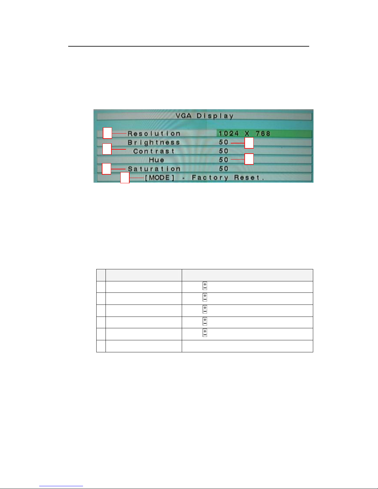
7.4 VGA Display
In Menu display, press ▲▼ to change the highlighted option to VGA Display, and
then press ENTER to call up VGA Display dialog as shown below.
This section explains how to adjust the Resolution, Brightness, Contrast, Hue and
Saturation of VGA display quality.
1
3
5
6
▲▼ (Mouse: Click in the respective item)
Press these buttons to select the items.
2
4
ESC
Press this button to escape from this screen, and return to previous display.
If the contents have been modified, a Save dialog will be shown to ask the user
to save the changes, press ENTER to exit and save, ESC to exit without saving.
Name Description
1 Resolution
2 Brightness
3 Contrast
4 Hue
5 Saturation
6
MODE (Mouse: Left click)
Press to adjust the Resolution.
Press to adjust the Brightness.
Press to adjust the Contrast.
Press to adjust the Hue.
Press to adjust the Saturation.
Click to restore the default setting.
29
2 3
Standalone DVR SEC-DVR304 User Manual
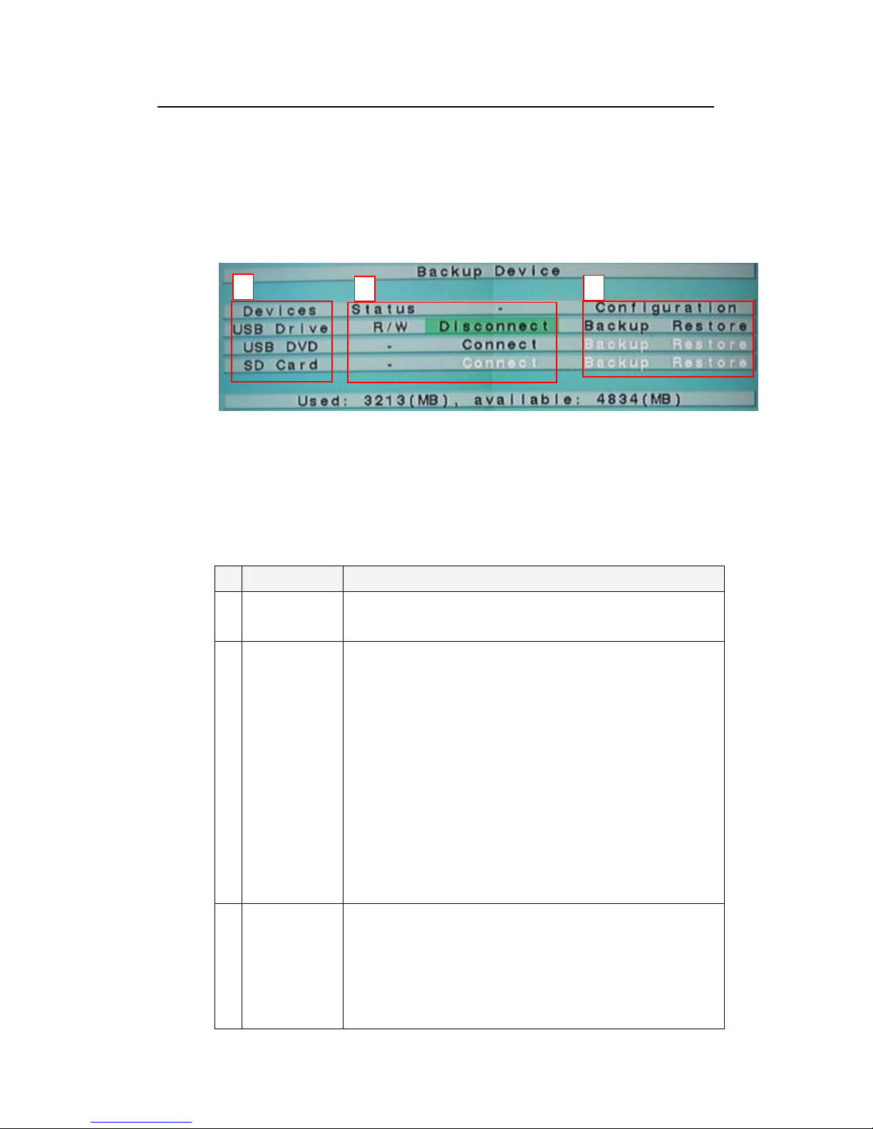
7.5 Backup Device
In Menu display, press ▲▼ to change the highlighted option to Backup Device,
and then press ENTER to call up Backup Device display as shown below.
This window allows user to view the connection status of the backup device and to
initiate data backup.
1
▲▼◄►
Press these buttons to select the items.
ESC
Press this button to escape from this screen, and return to MENU display.
Name Description
1 Devices Display a list of supported storage devices.
NOTE: USB CD-RW is not supported by this standalone DVR system.
2 Status Display the connection status of external storage device.
Connect/Disconnect–If the specific backup device is disconnected
(as shown in Current Status), please plug the USB device in one of
the USB ports of the system and/or insert a DVD for DVD device, and
then press ENTER (Mouse: Left click) to command the system to
connect with the device. If the specific device is already connected
(EX. Read/write, as shown in Current Status), please press ENTER
(Mouse: Left click) to command the system software to disconnect
with the device, and then unplug the backup device from the backup
port.
NOTE: IF you unplug USB Mouse while DVR is on, the USB Mouse
would not work even if you plug in the USB mouse again. Please
reboot Standalone DVR with USB mouse plug in. Access to BACK
Device operation, press ENTER to command the system to connect
with the device.
3 Configuration
Click Backup (Mouse: Left click) to store the data files to an
external storage device. For software V6.13 or above, you may
specify the directory to backup the configurations to.
Click Restore (Mouse: Left click) to restore the data files from the
external device to the local system. For software V6.13 or above,
you may specify the directory to restore the configurations
from.
30
8
Standalone DVR SEC-DVR304 User Manual
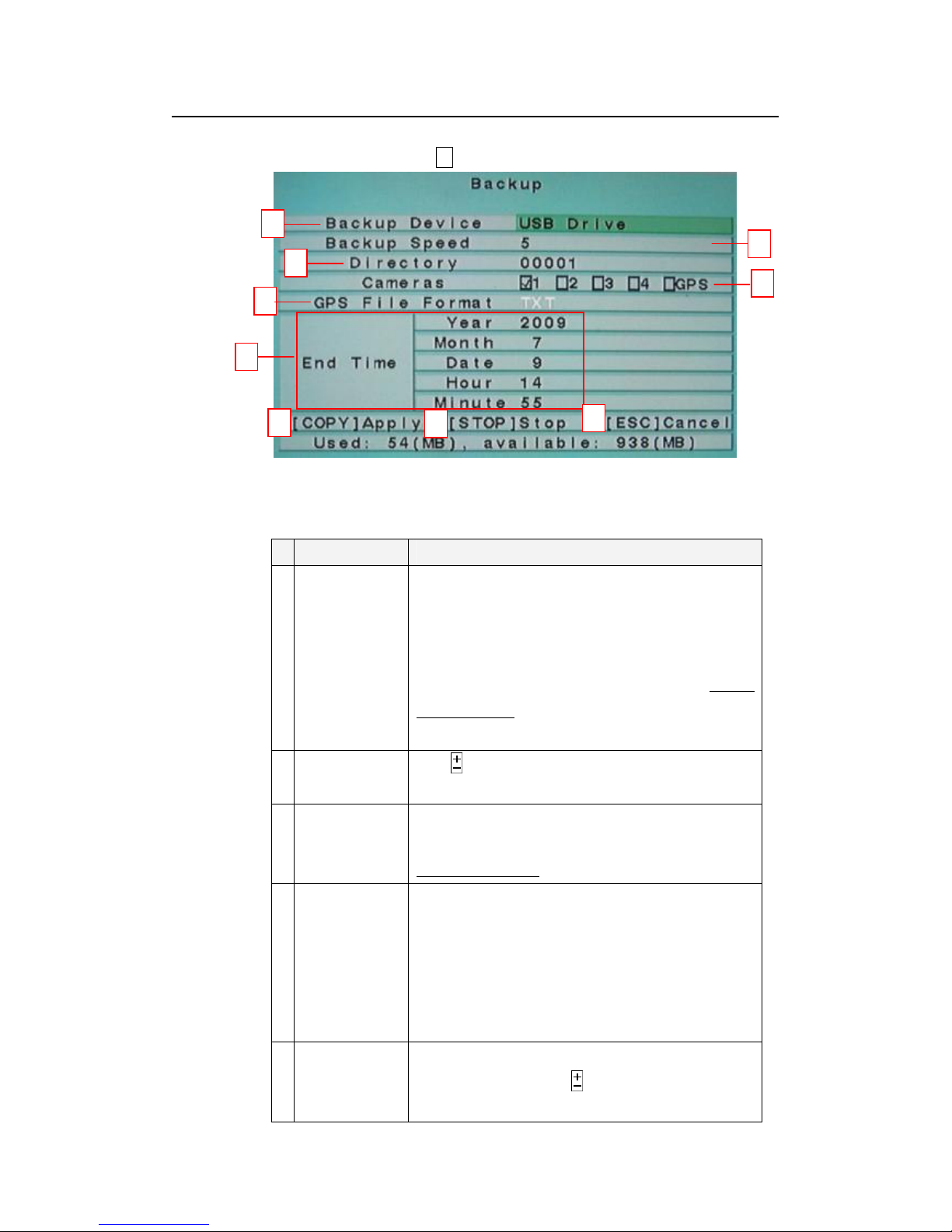
7.5.1 Backup Setting
Click on CALL / COPY ( ) to access the Backup setting.
1
2
3
4
5
6
7
9
▲▼◄►
Press these buttons to select the items.
Name Description
1 Backup Device The backup device connected to the system. Press
ENTER on the left button to call up Backup Device dialog
if there’s no backup device connected. Press +/- buttons
on the right selection to select the connected device for
the backup. Please follow the steps described in Chapter
7.5 Backup Device to connect the backup device before
copying.
2 Backup Speed
3 Directory The directory in the backup device to store the archived
Click to adjust the backup process speed.
(1-9, with 1 the lowest speed, 9 the highest speed.)
files. Please follow the Text Input method described in
Chapter 5.1 Text Input to input the directory.
4 Cameras The video/audio of the cameras to be archived. Press
5 GPS File Format for the backup of GPS data only. The supported formats
ENTER or +/- to select/deselect each of the selectable
cameras. If the camera with GPS data is selected, the
GPS data will be saved with the camera video in the
same file. The user may save GPS data only (without
saving camera video) by selecting GPS.
are TXT and KML. Click to set the GPS file format to
be saved. (※ Note: POS not supported)
 Loading...