

Page 1
1
CMP-WNROUT20 + 40
CMP-WNROUT40
MANUAL (p. 2)
WIRELESS 11N ROUTER 150M
WLAN ROUTER 300MBPS 11N
MODE D’EMPLOI (p. 13)
ROUTEUR 150M SANS FIL 11N
ROUTEUR WLAN 300MBPS 11N
MANUALE (p. 24)
WIRELESS 11N ROUTER 150M
WLAN ROUTER 300MBPS 11N
BRUKSANVISNING (s. 46)
TRÅDLÖS 11N ROUTER 150M
WLAN ROUTER 300MBPS 11N
MANUAL DE UTILIZARE (p. 57)
ROUTER WIRELESS 11N 150M
ROUTER WLAN 300MBPS 11N
HASZNÁLATI ÚTMUTATÓ (o. 35.)
VEZETÉK NÉLKÜLI 11N ÚTVÁLASZTÓ 150M
WLAN ÚTVÁLASZTÓ 300MBPS 11N
KÄYTTÖOHJE (s. 41)
LANGATON 11N REITITIN 150M
WLAN REITITIN 300MBPS 11N
ANLEITUNG (s. 7)
KABELLOSER 11N ROUTER 150 MBIT/S
WLAN ROUTER 300 MBIT/S 11N
GEBRUIKSAANWIJZING (p. 18)
DRAADLOZE 11N ROUTER 150M
WLAN ROUTER 300MBPS 11N
MANUAL DE USO (p. 29)
ROUTER INALÁMBRICO 11N DE 150M
ROUTER WLAN 11N DE 300MBPS
NÁVOD K POUŽITÍ (s. 51)
BEZDRÁTOVÝ 11N ROUTER 150M
WLAN ROUTER 300MBPS 11N
ΕΓΧΕΙΡΙΔΙΟ XPHΣHΣ (σελ. 62)
ΑΣΥΡΜΑΤΟ 11N ROUTER 150M
WLAN ROUTER 300MBPS 11N
Page 2
2
ENGLISH
Chapter 1: Introduction
1.1 LED Indicator and Port Description
Front Panel and LED Indicators
LED indicator description on front panel: (from L to R)
• POWER
When turns green, always ON indicates the power is connected.
• SYS
When turns green, flashing indicates the system runs well.
• WPS
When flashing, it indicates the device is communicating with client in WPS mode.
• WLAN
Wireless signal LED indicator. When turns green, flashing indicates the wireless function is enabled.
• LAN (4,3,2,1)
Wired local network LED indicator. Always ON indicates it is connected with Ethernet device; flashing indicates the
device is transmitting and/or receiving data.
• WAN
Wide area network indicator. Always ON indicates the Router’s W.
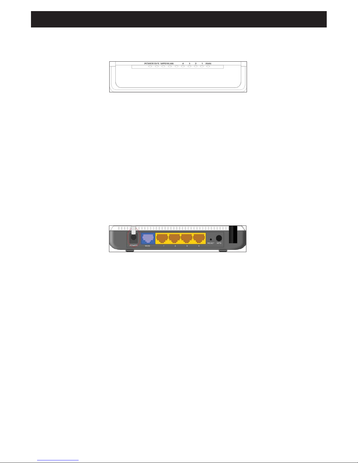
Rear Panel
Rear Panel: (From L to R)
• POWER
The jack is for power adapter connection. Please use the included 9V DC power adapter.
• WAN
A 100Mbps Ethernet port, can be connected with MODEM, switch, router and other Ethernet device for Internet
connecting to DSL MODEM, cable MODEM and ISP.
• LAN (1, 2, 3, 4)
4 10/100Mbps Ethernet ports can be connected with Ethernet switch, Ethernet router and NIC card.
• RESET
The system reset button. Press this button for 7 seconds, the settings configured in this device will be deleted and it
will restore the settings to default.
• WPS
Press for 1 second, the WPS feature will be enabled and WPS indicator will be flashing.
Chapter 2: Hardware Installation
2.1 How to Install the Router
Step 1: Please use the included power adapter to power on the Router. IMPORTANT: Use of a different power adapter
could cause damage and void the warranty for this product.
Step 2: Please connect the LAN port of the Router to the network adapter of your computer via cable.
Step 3: Please connect your broadband line provided by your ISP to the WAN port.
Step 4: Insert the included CD-ROM into the CD-ROM drive, double click the “Setup” icon and follow the instructions
to complete the installation. Or you can enter the router’s web page to configure. (More details please refer to
Chapter 3.)
Page 3

3
Chapter 3: How to Login to the Router
3.1 How to Set the Network Configuration
1. On your computer desktop right click “My Network Places” and select “Properties”.
2. Right click “Local Area Network Connection” and select “Properties”.
3. Select “Internet Protocol (TCP/IP)” and click “Properties”.
4. - Select “Obtain an IP address automatically” and “Obtain DNS server address automatically”. Click “OK” to save the
configuration.
- Or select “Use the following IP address” and enter the IP address, subnet mask, default gateway as follows: IP
Address: 192.168.0.XXX: (XXX is a number from 2~254) Subnet Mask: 255.255.255.0
Gateway: 192.168.0.1. Certainly you need to input the DNS server address provided by your ISP. Otherwise, you can
use the router’s default gateway as the DNS proxy server. Click “OK” to save the configuration.
3.2 Login to the Router
1. To access the router’s web-based interface, launch a web browser such as Internet Explorer or Firefox and enter the
router’s default IP address, http://192.168.0.1. Press “Enter”.
2. Input the “admin” in both User Name and Password. Click “OK”.
Chapter 4: Quick Setup Guide
4.1 Setup Wizard
Here is the “Welcome to Setup Wizard” for configuring your Router quickly. Click “Next”.
In this screen, select one mode of your Internet connection you use. If you are not clear, press the “Detect” button or
contact your Internet Service Provider, and click “Next”.
ADSL Virtual Dial-up (Via PPPoE)
Enter the Account and Password provided by your ISP, and click “Next”.
Dynamic IP (Via DHCP)
If your connection mode is Dynamic IP, it means your IP address keeps changing every time you connect. You do not
need to enter the information like other modes. Click “Next” and “Save” to finish the setting.
Static IP
In this screen, fill the network address information from your ISP in the IP Address, Subnet Mask, Gateway and Primary
DNS server fields and click “Next”.
L2TP
Consult your ISP for the required information.
Chapter 5: Advanced Settings
5.1 LAN Settings
LAN Settings are for the basic TCP/IP parameters of LAN ports.
•
IP Address: The Router’s LAN IP addresses (not your PC’s IP address). 192.168.0.1 is the default value.
•
Subnet Mask: Shows the router’s subnet mask for measurement of the network size. 255.255.255.0 is the default
value.
IMPORTANT:
Once you modify the IP address, you need to remember it for the web-based utility login next time.
5.2 WAN Settings
After you have selected the ISP connection type in “Setup Wizard” and you want to modify the related settings, here you
can modify and configure the settings in details.
Static IP
If connection mode static IP is selected, you can modify the following address information.
•
IP Address: Here enter the WAN IP address provided by your ISP.
•
Subnet Mask: Enter the WAN subnet mask here.
•
Gateway: Enter the WAN gateway here.
•
Primary DNS Server: Enter the primary DNS server provided by your ISP.
•
Secondary DNS Server: Enter the secondary DNS.
Page 4

4
Chapter 6: Wireless Setting
6.1 Basic Settings
•
Enable Wireless: Check to enable the router’s wireless features; uncheck to disable it.
•
Network Mode: Select one mode from the following. The default is 11b/g/n mode.
•
Main SSID: SSID (Service Set Identifier) is the unique name of the wireless network. This device has two SSID and
the main SSID is necessary.
•
Minor SSID: It is optional.
•
Broadcast (SSID): Select “Enable” to enable the device’s SSID to be visible by wireless clients. The default is
enabled.
•
MBSSID AP Isolation: One access control feature based on wireless MAC address. When this feature is enabled,
wireless clients connected with the same SSID cannot communicate with each other.
•
AP Isolation: One access control feature based on SSID. When this feature is enabled, each of your wireless clients
will be in its own virtual network and will not be able to communicate with each other. When this feature is enabled,
wireless clients connected with the main SSID and minor SSID cannot communicate with each other, which can
strongly secure the wireless network.
•
Channel: Specify the effective channel (from 1 to 13\Auto) of the wireless network.
•
Extension Channel: To increase data throughput of wireless network, the extension channel range is used in 11n mode.
•
Channel Bandwidth: Select the channel bandwidth to improve the wireless performance. When the network has
11b/g and 11n clients, you can select 40M; when it is an 11n network, select 20/40M to improve its throughput.
6.2 Wireless Security Setting
It is used to configure the AP network’s security setting. Here it presents the common six (ten in all) encryption methods,
including Mixed WEP, WPA-personal, WPA-enterprise, WPA2-personal, WPA2- enterprise, etc.
6.2.1 Mixed WEP
WEP (Wired Equivalent Privacy), a basic encryption method, usually encrypts wireless data using a series of digital
keys (64 bits or 128 bits in length). By using the same keys on each of your wireless network devices, you can prevent
unauthorized wireless devices from monitoring your transmissions or using your wireless resources. Select Mixed WEP to
enter the following window:
•
Select SSID: Select the SSID (main SSID or minor SSID) to configure security setting from the drop-down menu.
•
Security Mode: From the drop-down menu select the corresponding security encryption modes.
•
WEP Key1~4: Set the WEP key with the format of ASCII and Hex. You can enter ASCII code (5 or 13 ASCII
characters. Illegal character as “/” are not allowed.) Or 10/26 hex characters.
•
Default Key: Select one key from the four configured keys as the currently available one.
6.2.2 WPA-Personal
WPA (Wi-Fi Protected Access), a Wi-Fi standard, is a more recent wireless encryption scheme, designed to improve the
security features of WEP. It applies more powerful encryption types (such as TKIP [Temporal Key Integrity Protocol] or
AES [Advanced Encryption Standard]) and can change the keys dynamically on every authorized wireless device.
•
Select SSID: Select the SSID (main SSID or minor SSID) to configure security setting from the drop-down menu.
•
WPA Algorithms: Provides TKIP [Temporal Key Integrity Protocol] or AES [Advanced Encryption Standard]. The
default is TKIP mode.
•
Pass Phrase: Enter the encrypted characters with 8-63 ASCII characters.
•
Key Renewal Interval: Set the key’s renewal period.
6.2.3 WPA2- Personal
WPA2 (Wi-Fi Protected Access version 2) provides higher security than WEP (Wireless Equivalent Privacy) and WPA (WiFi Protected Access).
•
Select SSID: Select the SSID (main SSID or minor SSID) to configure security setting from the drop-down menu.
•
WPA Algorithms: Provides TKIP [Temporal Key Integrity Protocol] or AES [Advanced Encryption Standard]. The
default is TKIP mode.
•
Pass Phrase: Enter the encrypted characters with 8-63 ASCII characters.
•
Key renewal Interval: Set the key’s renewal period.
Page 5

5
6.2.4 WPA- Enterprise
This security mode is used when a RADIUS server is connected to the device. Select “WPA-Enterprise” from the dropdown menu to enter the following window:
•
Select SSID: Select the SSID (main SSID or minor SSID) to configure security setting from the drop-down menu.
•
WPA Algorithms: Provides TKIP [Temporal Key Integrity Protocol] or AES [Advanced Encryption Standard]. The
default is TKIP mode.
•
Key Renewal Interval: Set the key’s renewal period.
•
Radius Server: Enter the IP address of the Radius server.
•
Radius Server port: Enter the authentication port of the Radius server. The default is 1812.
•
Shared Secret: Enter the shared key for authentication server with 8~63 ASCII characters.
•
Session Timeout: The authentication interval period between AP and authentication server.
6.2.5 WPA2-Enterprise
This security mode is based on Radius authentication server and WPA2 encryption method. WPA2 is used when a
RADIUS server is connected to the device. Select “WPA2-Enterprise” from the drop-down menu to enter the following
window:
•
Select SSID: Select the SSID (main SSID or minor SSID) to configure security setting from the drop-down menu.
•
WPA Algorithms: Provides TKIP [Temporal Key Integrity Protocol] or AES [Advanced Encryption Standard]. The
default is TKIP mode.
•
Key Renewal Interval: Set the key’s renewal period.
•
Radius Server: Enter the IP address of the Radius server.
•
Radius Server port: Enter the authentication port of the Radius server. The default is 1812.
•
Shared Secret: Enter the shared key for authentication server with 8~63 ASCII characters.
•
Session Timeout: The authentication interval period between AP and authentication server. The default is 3600s.
6.2.6 802.1X
This security mode is used when a RADIUS server is connected to the device. 802.1x, a kind of port-based authentication
protocol, is an authentication type and strategy for users. The port can be either a physical port or logical port (such as
VLAN). For wireless LAN users, a port is just a channel. The final purpose of 802.11x authentication is to check if the port
can be used. If the port is successfully authenticated, you can open this port which allows all the messages to pass. If the
port is not successfully authenticated, you can keep this port “disabled”, which just allows 802.1x authentication protocol
messages to pass. Select “802.1x” from the drop-down menu to enter the following window:
•
Select SSID: Select the SSID (main SSID or minor SSID) to configure security setting from the drop-down menu.
•
WEP: Click “Enable/Disable” to enable or disable the WEP algorithm.
•
Radius Server: Enter the IP address of the Radius server.
•
Radius Server Port: Enter the authentication port of the Radius server. The default is 1812.
•
Shared Secret: Enter the shared key for authentication server with 8~63 ASCII characters.
•
Session Timeout: The authentication interval period between AP and authentication server. The default is 3600s.
6.3 WPS Settings
WPS (Wi-Fi Protected Setting) can be used to establish the connection between the wireless network clients and the
device through encrypted contents easily and quickly. The users only enter PIN code or press WPS button on the panel
to configure it without selecting encryption method and secret keys manually. In the “Wireless settings” menu, click “WPS
settings” to enter the next screen.
•
WPS settings: To enable or disable WPS function. The default is “disable”.
•
WPS mode: Provide two ways: PBC (Push-Button Configuration) and PIN code.
•
PBC: Select PBC or press the WPS button on the front panel of the device for about one second. (Press the button
for about one second and WPS indicator will be flashing for 2 minutes, which means the WPS is enabled. During
flashing, you can enable another device to implement the WPS/PBC negotiation between them. Two minutes later, the
WPS indicator will turn off, which means that the WPS connection is completed. If more clients are added, repeat the
above steps. At present, the WPS supports up to 32 clients access.)
•
PIN: If this option is enabled, you need to enter a wireless client’s PIN code in the field and keep the same code in the
WPS client.
Page 6

6
6.4 WDS Settings
WDS (Wireless Distribution System) is used to expand wireless coverage area. This router provides three modes: Lazy,
Bridge and Repeater.
Lazy: In this mode, the connected device can be Bridge mode or Repeater mode and enter the router’s BSSID to
establish the connection.
Bridge: You can wirelessly connect two or more wired networks via this mode. In this mode, you need to add the Wireless
MAC address of the connecting device into the router’s AP MAC address table or select one from the scanning table.
Repeater Mode: In this mode, add the opposing MAC address into each own AP MAC address table manually or by
scanner to enlarge and extend the wireless radio.
Chapter 7: DHCP Server
7.1 DHCP Settings
DHCP (Dynamic Host Control Protocol) is to assign an IP address to the computers on the LAN/private network. When
you enable the DHCP Server, the DHCP Server will allocate automatically an unused IP address from the IP address pool
to the requesting computer in premise of activating “Obtain an IP Address Automatically”. So specifying the starting and
ending address of the IP Address pool is needed.
•
DHCP Server: Activate the checkbox to enable DHCP server.
•
IP Address Start/End: Enter the range of IP addresses for DHCP server distribution.
•
Lease Time: The length of the IP address lease.
Chapter 8: Upgrade Firmware
8.1 The Router provides the firmware upgrade by clicking “Upgrade” after browsing the firmware upgrade packet,
which you can download from www.nedis.nl
•
Browse: Click this button to select the upgrade file.
•
Upgrade: Click this button to start the upgrading process. After the upgrade is completed, the router will reboot
automatically.
8.2 Reboot the Router
Rebooting the Router makes the settings configured go into effect or to set the router again if setting failure occurs.
8.3 Password Change
This section is to set a new user name and password to better secure your router and network.
•
User Name: Enter a new user name for the device.
•
Old Password: Enter the old password.
•
New Password: Enter a new password.
•
Re-enter to Confirm: Re-enter to confirm the new password.
8.4 Logout
After you have finished the settings completely, in logout page click “Yes” to logout the web management page.
Safety precautions:
To reduce risk of electric shock, this product should ONLY be opened by an authorized
technician when service is required. Disconnect the product from mains and other
equipment if a problem should occur. Do not expose the product to water or moisture.
Maintenance:
Clean only with a dry cloth. Do not use cleaning solvents or abrasives.
Warranty:
No guarantee or liability can be accepted for any changes and modifications of the product or damage caused due to
incorrect use of this product.
RISK OF ELECTRIC SHOCK
DO NOT OPEN
CAUTIO N
 Loading...