

Page 1
56
TESTER KABELU LAN
44
LAN-KAAPELIN TESTAAJA
32
PROBADOR DE CABLE LAN
20
LAN-KABELTESTER
8
LAN-KABELPRÜFER
62
TESTER CABLU LAN
50
LAN-KABELTESTARE
38
LAN KÁBELTESZTER
26
TESTER CAVI LAN
14
TESTEUR DE CÂBLE RÉSEAU
LAN CABLE TESTER
CMP-RCT31
Page 2
2
ENGLISH
Introduction:
This König cable tester reads the correct pin confi guration of the different LAN cables, by
comparing the transmitting end to the corresponding receiving end. With the remote unit
it’s easy to test existing cables and connections. Ideal to test wires which are behind walls
or ceilings. It is easy to verify the cable continuity, open, short and cross-connect.
Features:
• Can test the correct pin confi guration of 10Base-T, 10Base-2 Ethernet cable, RJ45/
RJ11 modular cables, 258A, TIA-568A/568B and Token Ring cable etc.
• Easy to read cable status and verify cable continuity, open, short and miss wiring.
• With the remote unit it’s easy to test existing cables and connections which are behind
walls or ceilings.
• Can test with grounding.
• Auto or manual scan.
Specifi cations:
• Transmitter
Connections: 2x RJ45
Indication: LED
Switch: On/Off
Switch: Auto/Manual
Switch: Test
• Remote unit
Connections: RJ45
Indication: LED
• Power: 9 V Block (not included)
• Housing: Plastic
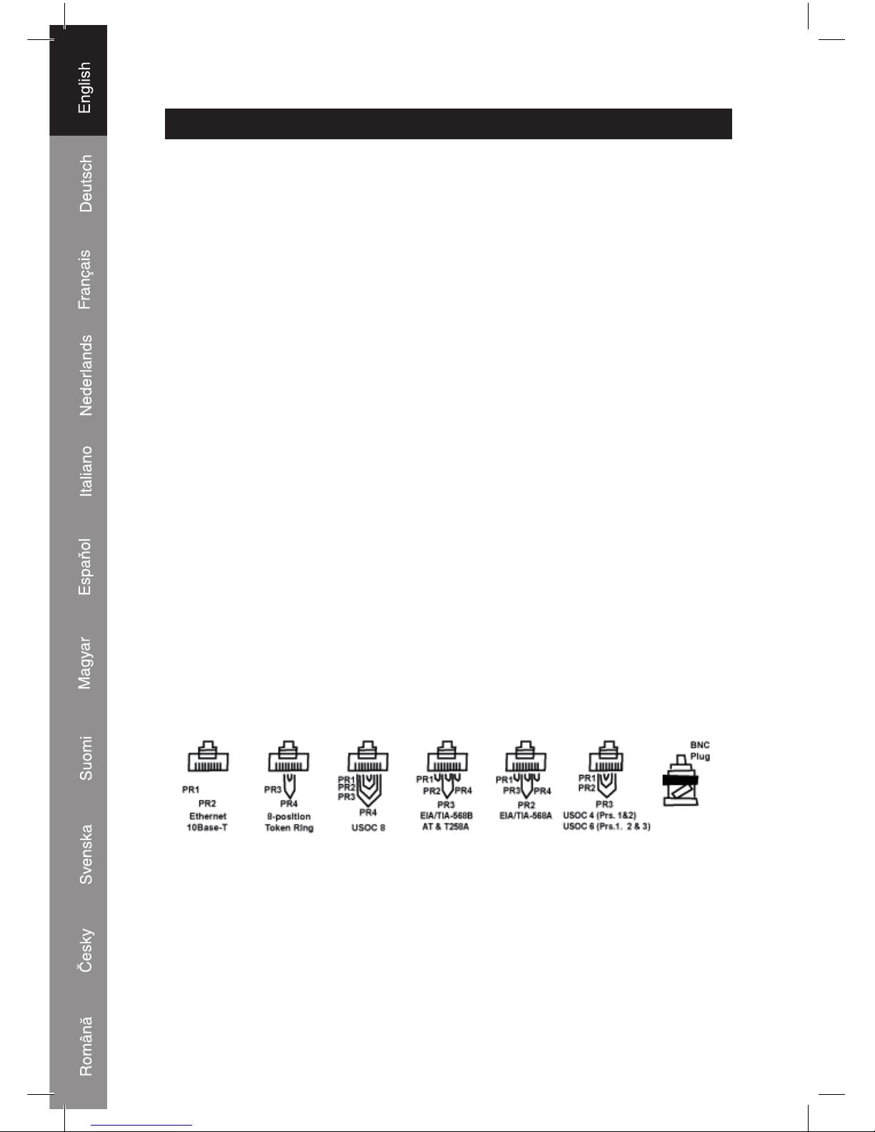
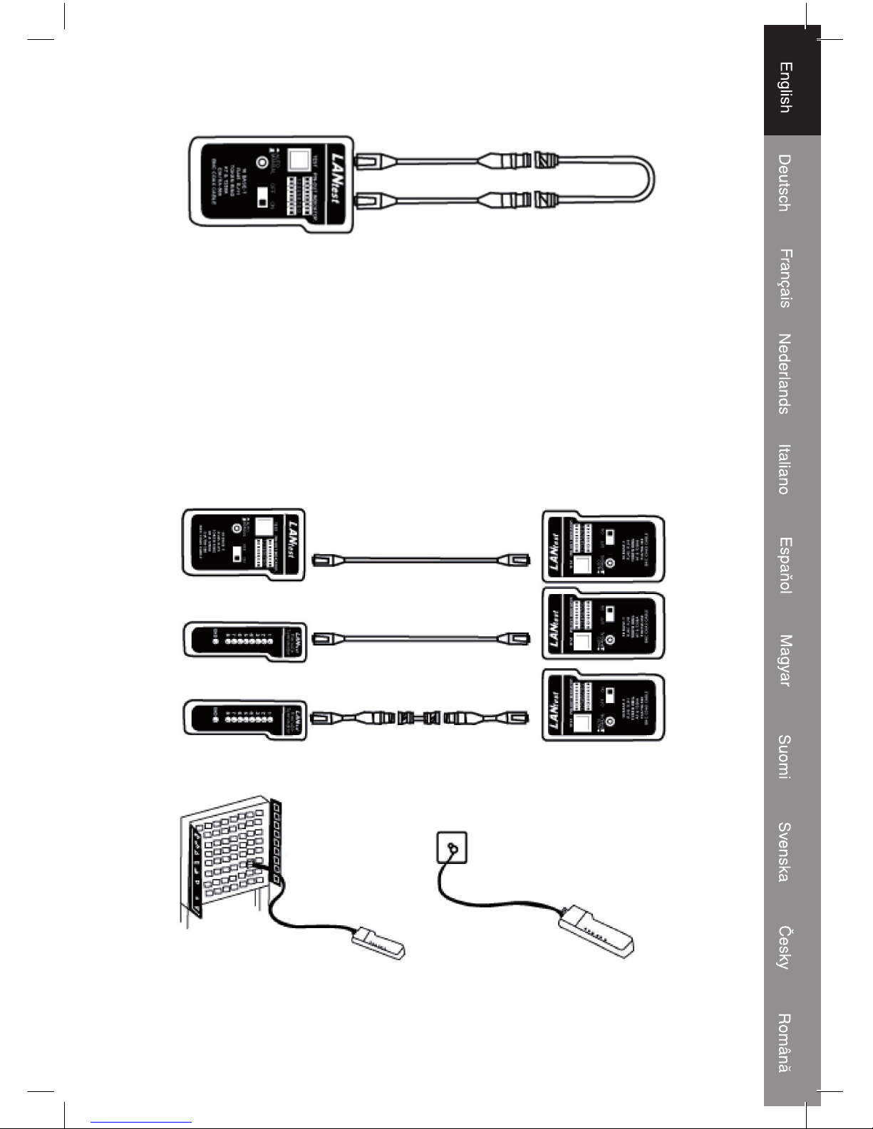
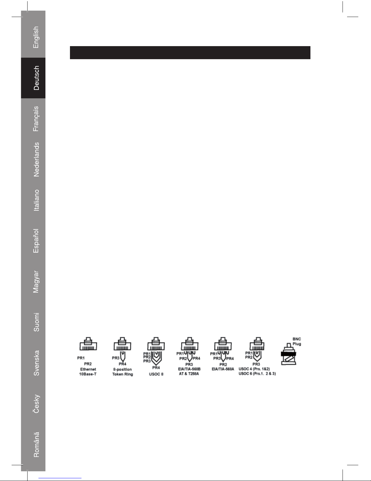
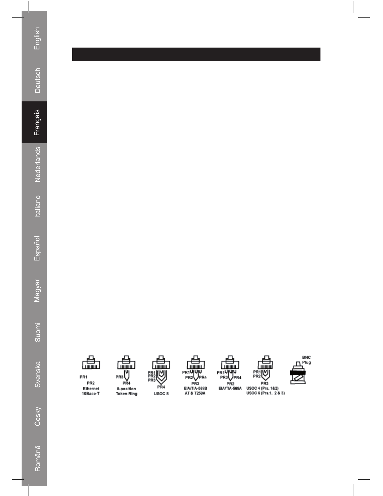
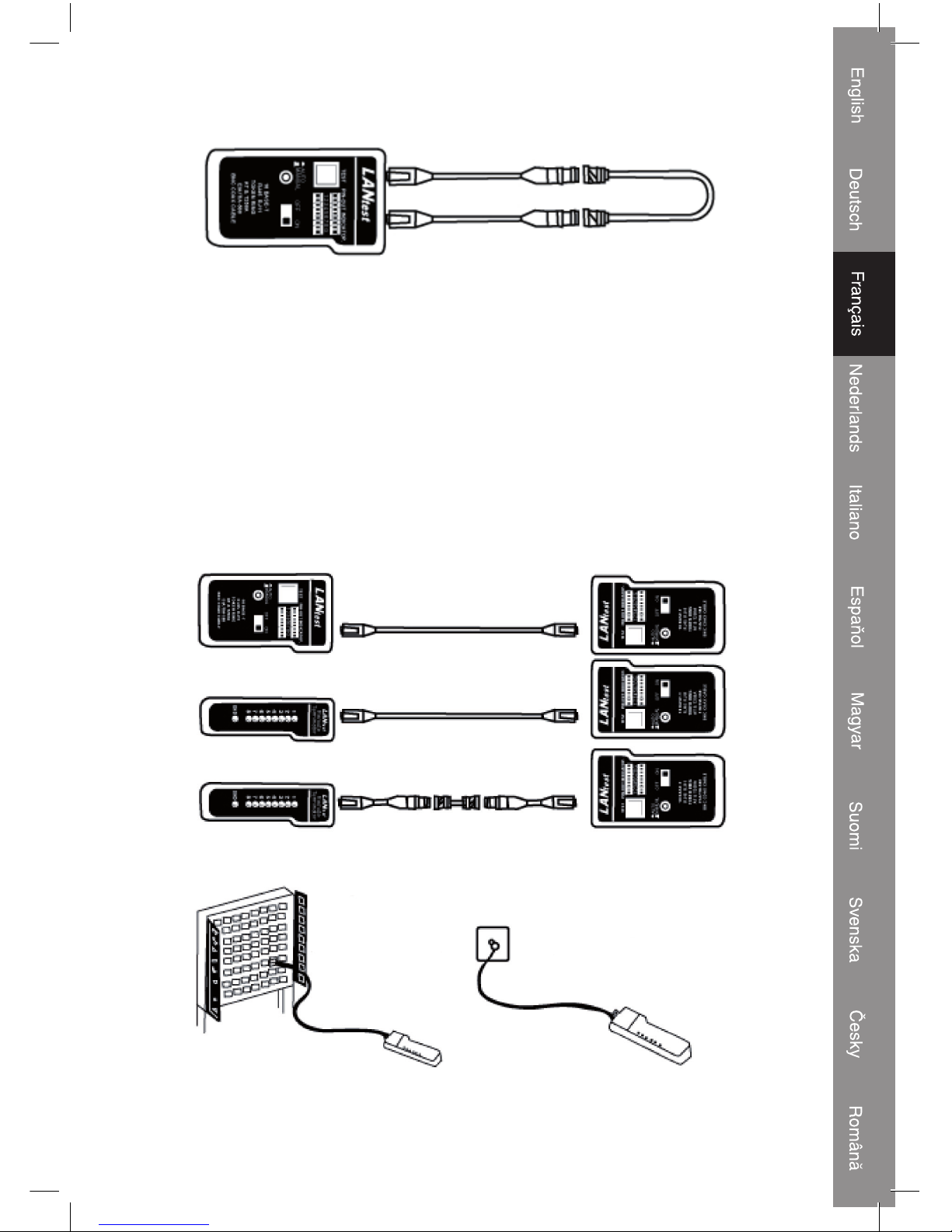
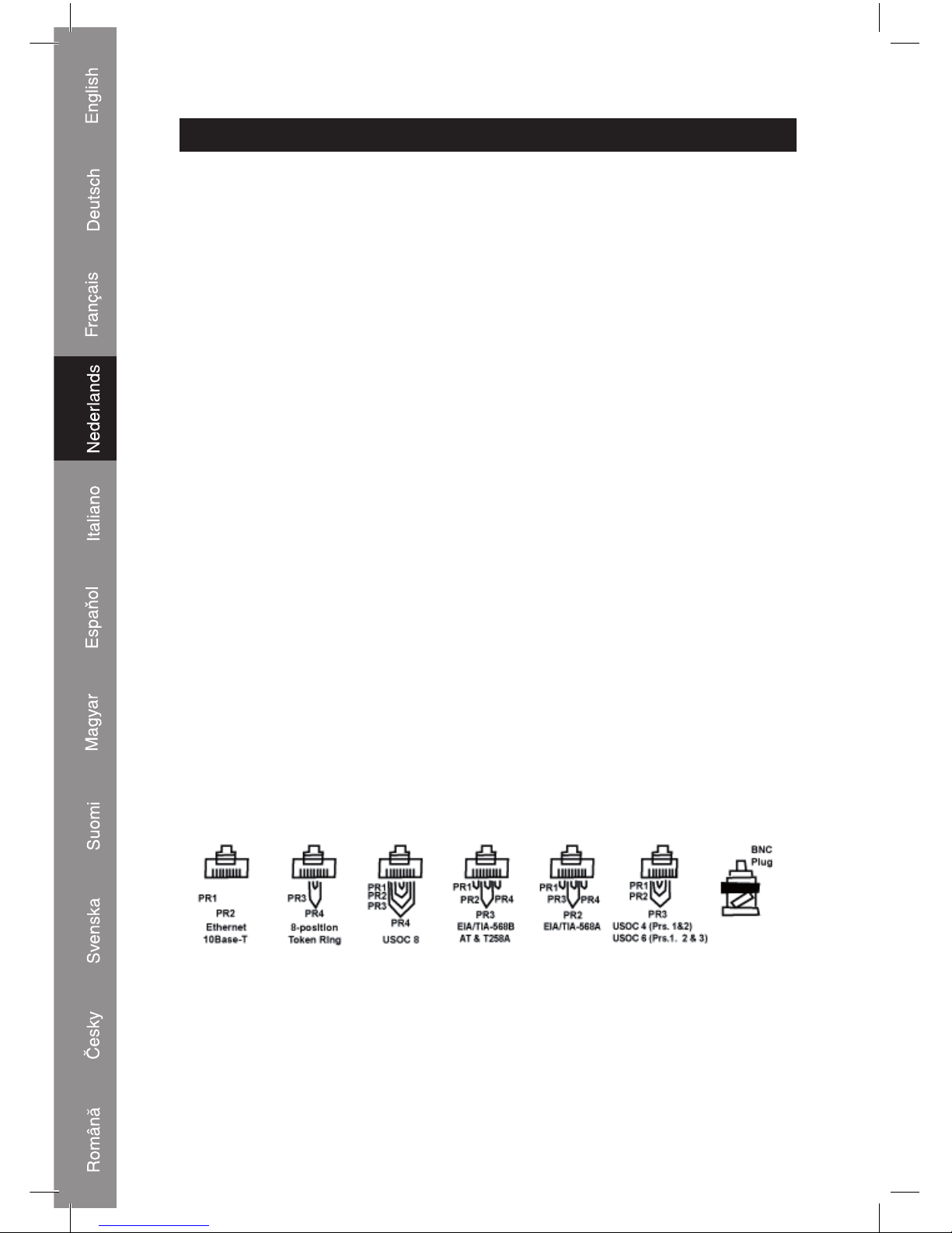
Connections:
Page 3
3
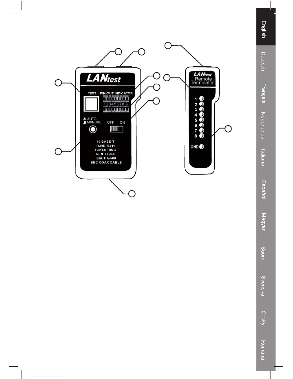
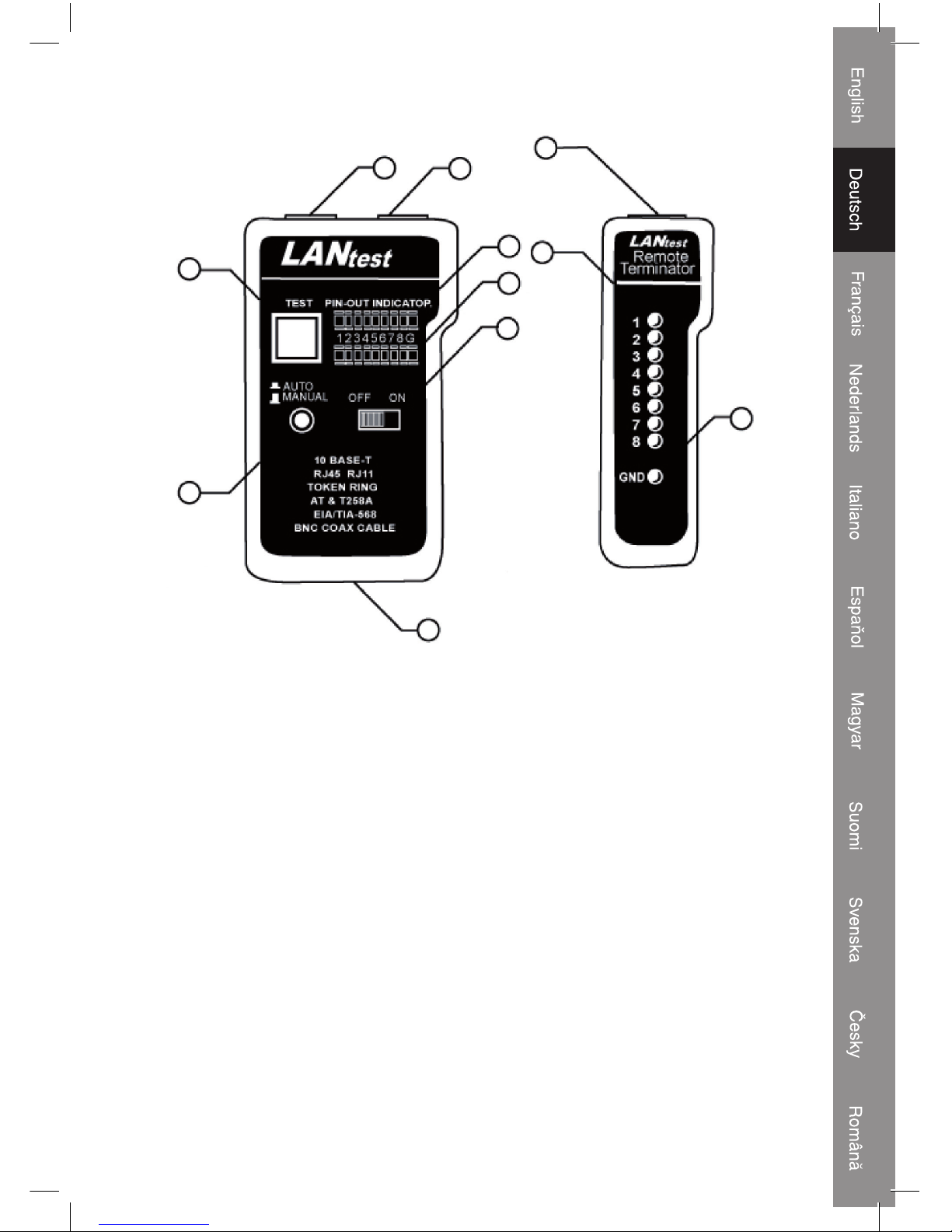
Master
Unit
Remote
Unit
1) RJ45 jack
2) RJ45 jack
3) LED display for sourcing end (jack 1)
4) LED display for receiving end (jack 2)
5) Power switch
6) LED scanning mode switch
7) Test switch for manual scan
8) RJ45 jack
9) LED display for receiving end (same as jack 2)
10) Ground LED for receiving end
11) Battery compartment (9 V block)
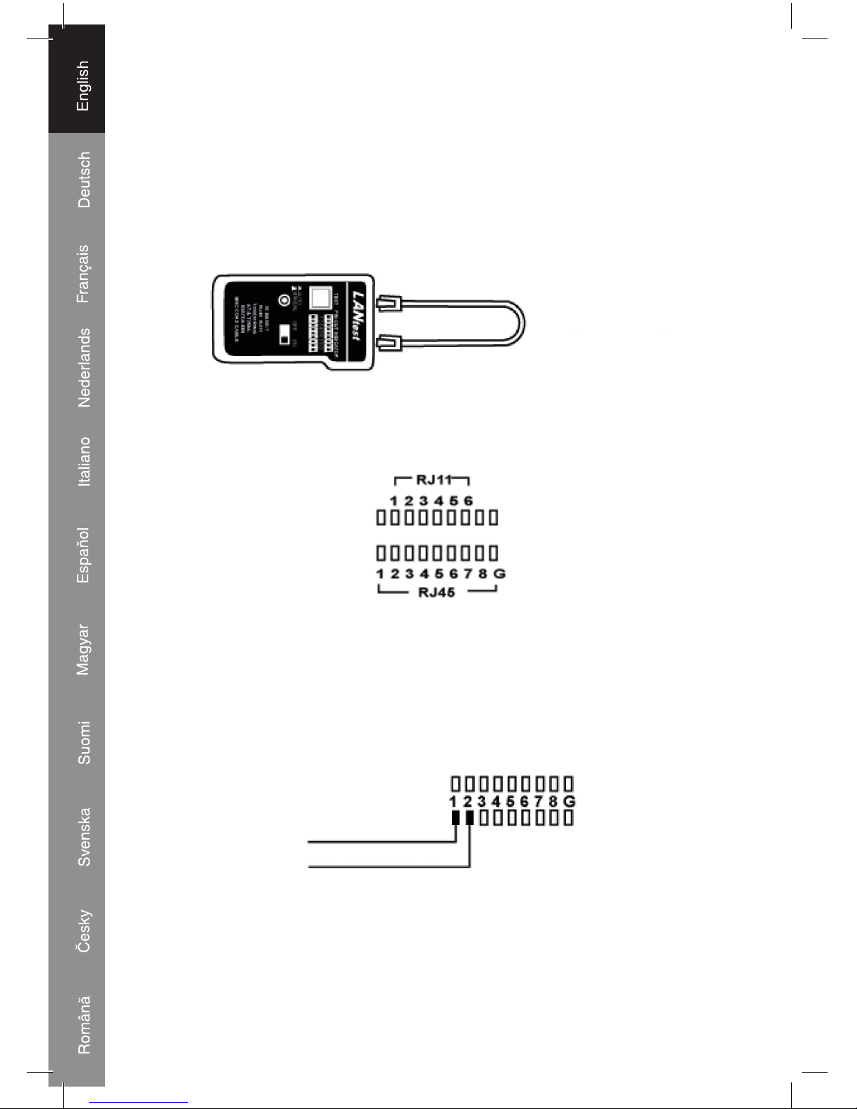
Operation and connection:
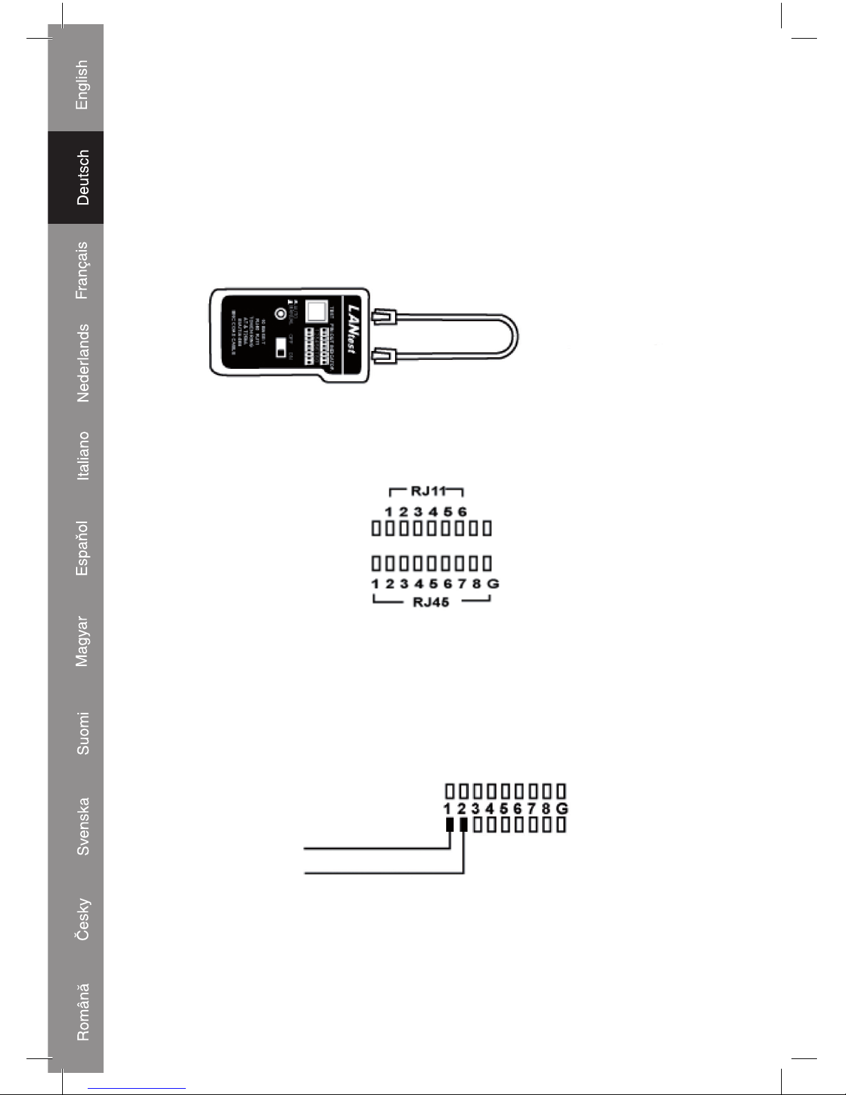
Loopback test
1) 10Base-T cable test.
• Plug one end of the to be tested cable into the sourcing of the RJ45 jack
(marked with “”) and another end of the to be tested cable in the receiving RJ45 jacks.
7
6
11
1
8
9
10
2
3
4
5
Page 4
4
• Slide power switch on. When in auto mode the LEDs will light up in sequence to indicate
the status of the wire. When in manual mode the fi rst LED will light up, showing you the
status of the fi rst wire. Press a button on the remote unit to continue to the next wire.
• Choose the Auto/Manual switch for Auto scan mode or Manual scan mode by pressing
the Auto/Manual switch.
• When a wire is good, the upper and lower LED will light up simultaneously.
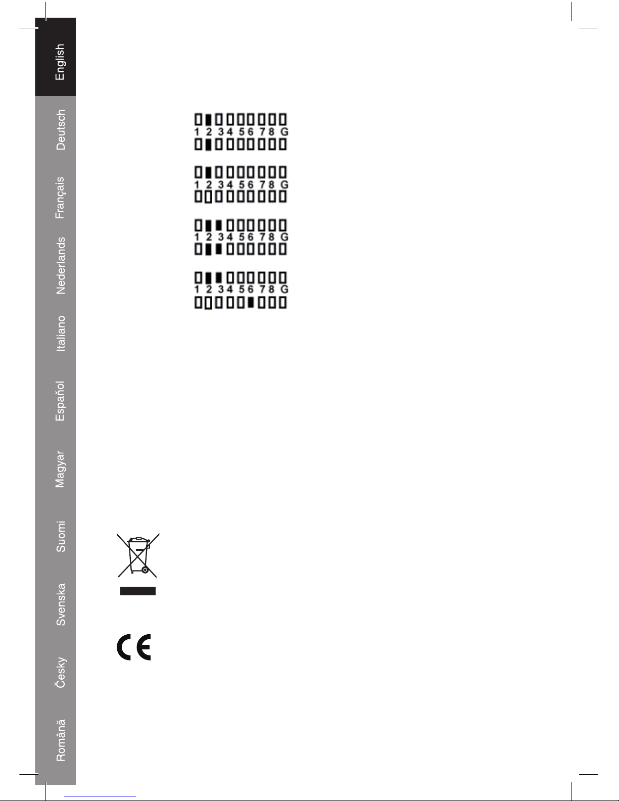
Loopback Test
2) Modular cable test
• Please follow up the procedures of 10Base-T cable test. However the LED display
should be read as the picture below.
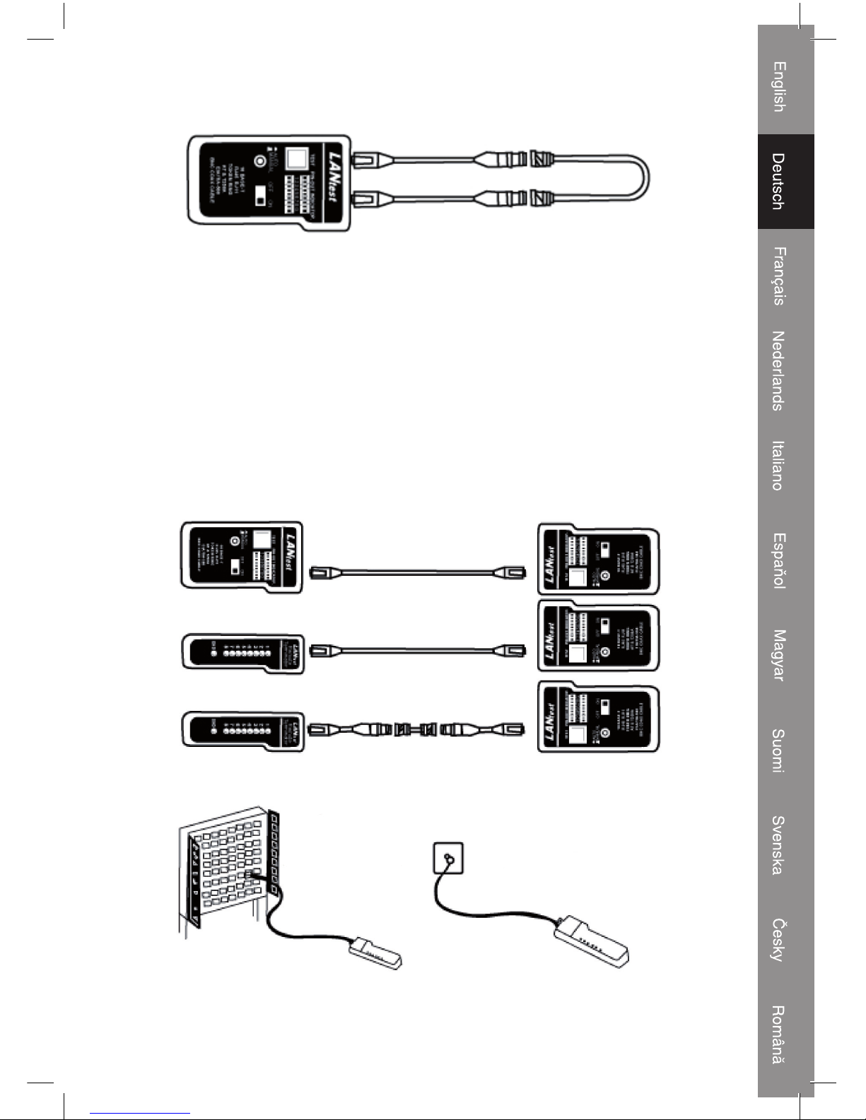
3) 10Base-2 cable test
• Plug the 2 attached BNC adaptor cables on both RJ45 jacks, then connect the to be
tested cable to both ends of the BNC adaptor cables.
• For the remaining procedures you may refer to the 10Base-T cable test.
Note: The center pin of BNC should be read on LED 1 and shielding pin of BNC should
be read on LED 2 (see picture below)
BNC CENTER PIN
BNC SHIELDING
Note 2: As the 10Base-2 cable has only 2 wires, we suggest you read the result of the
LED scan via manual mode.
Page 5
5
Remote test
• Plug one end of the to be tested cable into the sourcing RJ45 jack ( marked with “”) of
the master unit and the end of the cable to the receiving RJ45 jack of the remote unit. If
the to be tested cable is already installed on the patch panel or wall plate, you can use
the adaptor cable to solve the connector gender problem.
• Switch to auto mode when you are performing this test alone. This way the tester will
automatically test all the wires inside the cable, without you needing to push the buttons
on the remote unit.
• Read the test result from the LED display on the remote unit.
Note: The LED display indicates the wires in the same sequence in auto mode as in
manual mode.
Remote Test
Patch Panel Wall Panel
Page 6
6
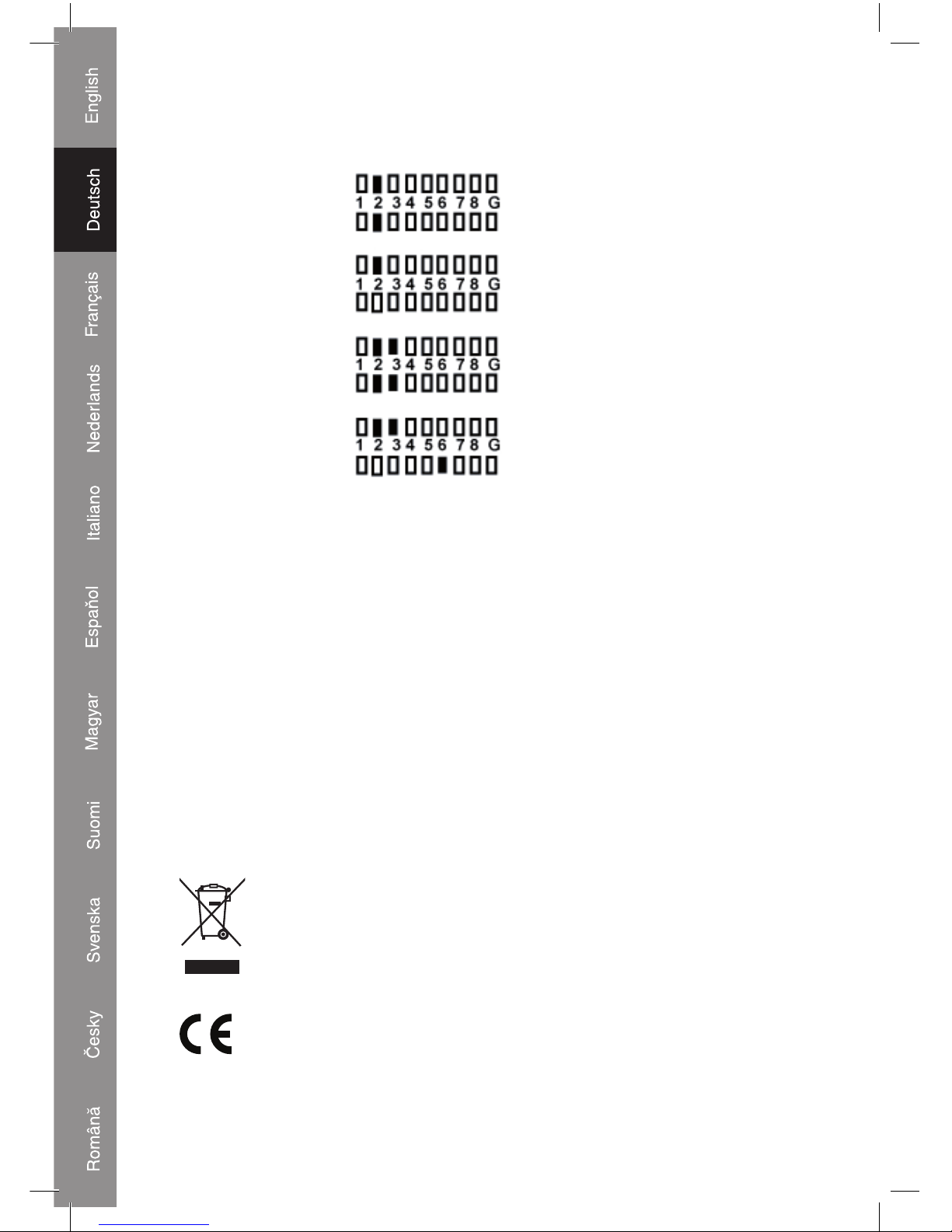
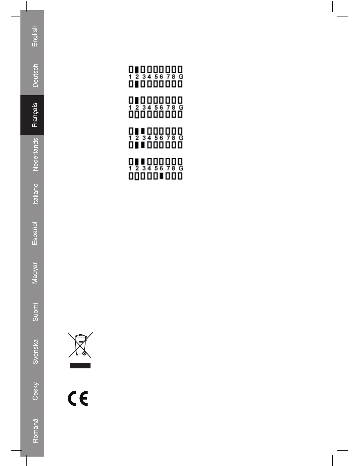
Test result
1. Continuity pin 2 is continued
2. Open pin 2 is opened
3. Short pin 2 and pin 3 are shorted
4. Miss wire pin 3 and pin 6 are miss wired|
Safety precautions:
Do not expose the product to water or moisture.
Maintenance:
Clean only with a dry cloth. Do not use cleaning solvents or abrasives.
Warranty:
No guarantee or liability can be accepted for any changes and modifi cations of the
product or damage caused due to incorrect use of this product.
General:
Designs and specifi cations are subject to change without notice.
All logos brands and product names are trademarks or registered trademarks of their
respective holders and are hereby recognized as such.
Attention:
This product is marked with this symbol. It means that used electrical and
electronic products should not be mixed with general household waste. There
is a separate collections system for these products.
Copyright ©
Page 7
7
Declaration of conformity
We,
Ned is B.V.
De Tweeling 28
5215MC ’s-Hertogenbosch
The Netherlands
Tel.: 0031 73 599 1055
Email: info@nedis.com
Declare that product:
Name: König Electronic
Model: CMP-RCT31
Description: Lan cable tester
Is in conformity with the following standards
EMC: EN 61000-6-1:2001
EN 61000-6-3:2001 + A11:2004
Following the provisions of the 2004/108/EC directive.
‘s-Hertogenbosch, 01 July 2008
Mrs. J. Gilad
Purchase Director
Page 8
8
DEUTSCH
Einleitung:
Dieser Kabelprüfer von König misst die richtige Stiftkonfi guration der verschiedenen
LAN-Kabel durch Vergleich der Sendeseite mit der entsprechenden Empfangsseite. Mit
dem Ferngerät ist es leicht, die vorhandenen Kabel und Anschlüsse zu prüfen. Er ist
ideal, um Kabel hinter Wänden oder Decken zu prüfen. Es ist leicht zu erkennen, ob das
Kabel durchgängig, offen, kurzgeschlossen oder kreuzgeschaltet ist.
Merkmale:
• Kann die richtige Stiftkonfi guration der Ethernetkabel 10Base-T und 10Base-2, der
modularen Kabel RJ45/RJ11, der 258A-, TIA-568A/568B- und Token Ring-Kabel usw.
prüfen.
• Leicht zu messender Kabelstatus und leicht zu erkennen, ob das Kabel durchgängig,
offen, kurzgeschlossen oder falsch verkabelt ist.
• Mit dem Ferngerät können vorhandene Kabel und Anschlüsse hinter Wänden oder
Dächern leicht geprüft werden.
• Kann mit Abschirmung prüfen.
• Hat automatische und manuelle Suche.
Technische Daten:
• Transmitter
Anschlüsse: 2x RJ45
Anzeige: LED
Schalter: An/Aus
Schalter: Automatisch/Manuell
Schalter: Prüfen
• Ferngerät
Anschlüsse: RJ45
Anzeige: LED
• Stromversorgung: 9 V-Block (nicht beigefügt)
• Gehäuse: Plastik
Anschlüsse:
Page 9
9
Hauptgerät Ferngerät
1) RJ45-Buchse
2) RJ45-Buchse
3) LED-Display für Sendeseite (Buchse 1)
4) LED-Display für Empfangsseite (Buchse 2)
5) Netzschalter
6) Schalter und LED für Such-Modus
7) Prüf-Schalter für manuelle Suche
8) RJ45-Buchse
9) LED-Display für Empfangsseite (wie Buchse 2)
10) Erdungs-LED für Empfangsseite
11) Batteriefach (9 V-Block)
Bedienung und Anschluss:
Testschleife
1) 10Base-T-Kabelprüfung.
• Stecken Sie ein Ende des zu prüfenden Kabels in die sendende RJ45-Buchse
(gekennzeichnet durch “”) und das andere Ende des zu prüfenden Kabels in die
empfangende RJ45-Buchse.
7
6
11
1
8
9
10
2
3
4
5
Page 10
10
• Schieben Sie den Netzschalter auf "ON". Wenn die LEDs im automatischen Modus
leuchten, wird der Reihe nach der Status der Adern angezeigt. Wenn im manuellen
Modus die erste LED leuchtet, wird Ihnen der Status der ersten Ader angezeigt. Drücken
Sie eine Taste am Ferngerät, um zur nächsten Ader zu gehen.
• Durch Drücken des Auto/Manual-Schalters können Sie zwischen automatischem und
manuellem Suchmodus umschalten.
• Wenn eine Ader gut ist, leuchten die obere und untere LED gleichzeitig.
Testschleife
2) Prüfung von modularem Kabel
• Befolgen Sie bitte die Verfahren für die 10Base-T-Kabelprüfung. Auf der LED-Anzeige
sollte jedoch folgendes Bild angezeigt werden:
3) 10Base-2-Kabelprüfung
• Stecken Sie die beiden beigefügten BNC-Adapterkabel in beide RJ45-Buchsen, dann
schließen Sie das zu prüfende Kabel an beide Enden der BNC-Adapterkabel an.
• Das restliche Vorgehen ist wie bei der 10Base-T-Kabelprüfung.
Hinweis: Der mittlere Stift des BNC-Adapters ist an LED1 und der abschirmende Stift ist
an LED2 abzulesen (siehe Abbildung unten).
BNC MITTLERER STIFT
BNC ABSCHIRMUNG
Hinweis 2: Da das 10Base-2-Kabel nur zwei Adern hat, schlagen wir vor, das Ergebnis
der Suche im manuellen Modus von der LED abzulesen.
Page 11
11
Fernprüfung
• Stecken Sie ein Ende des zu prüfenden Kabels in die sendende RJ45-Buchse
(gekennzeichnet durch “”) des Hauptgeräts und das andere Ende des Kabels in die
empfangende Buchse des Ferngeräts. Wenn das zu prüfende Kabel bereits auf der
Schalttafel oder Wandtafel installiert ist, können Sie das Adapterkabel benutzen, um
Probleme mit der Art des Anschlusses zu lösen.
• Schalten Sie in den automatischen Modus um, wenn Sie diese Prüfung allein
durchführen. Dadurch überprüft das Prüfgerät alle Adern im Kabel automatisch, ohne
dass Sie die Tasten am Ferngerät drücken müssen.
• Lesen Sie das Prüfergebnis vom LED-Display am Ferngerät ab.
Hinweis: Das LED-Display zeigt die Adern im automatischen Modus in derselben
Reihenfolge wie im manuellen Modus an.
Fernprüfung
Schalttafel Wandtafel
Page 12
12
Prüfergebnis
1. Durchgang
Stift 2 ist durchgängig
2. Offen Stift 2 ist offen
3. Kurzschluss Stifte 2 und 3 sind kurzgeschlossen
4. Falsch verdrahtet Stifte 3 und 6 sind falsch verdrahtet
Sicherheitsvorkehrungen:
Sorgen Sie dafür, dass das Gerät nicht mit Wasser oder Feuchtigkeit in Berührung
kommt.
Wartung:
Nur mit einem trockenen Tuch säubern. Keine Reinigungs- oder Scheuermittel
verwenden.
Garantie:
Es wird keine Garantie oder Gewährleistung bei Veränderungen, Modifi kationen oder
Schäden durch unsachgemäße Behandlung des Produktes gewährt.
Allgemeines:
Konstruktionen und technische Daten können ohne vorherige Ankündigung geändert
werden.
Alle Logos, Marken und Produktnamen sind Warenzeichen oder registrierte Warenzeichen
ihrer jeweiligen Eigentümer und werden hiermit als solche anerkannt.
Achtung:
Dieses Produkt ist mit diesem Symbol gekennzeichnet. Es bedeutet, dass die
verwendeten elektrischen und elektronischen Produkte nicht im allgemeinen
Haushaltsmüll entsorgt werden dürfen. Für diese Produkte stehen gesonderte
Sammelsysteme zur Verfügung.
Copyright ©
Page 13
13
KONFORMITÄTSERKLÄRUNG
Wir,
Ned is B.V.
De Tweeling 28
5215MC ’s-Hertogenbosch
Niederlande
Tel.: 0031 73 599 1055
Email: info@nedis.com
erklären, dass das Produkt:
Marke: König Electronic
Modell: CMP-RCT31
Beschreibung: LAN-Kabelprüfer
den folgenden Standards entspricht:
EMV: EN 61000-6-1:2001
EN 61000-6-3:2001 + A11:2004
Das bezeichnete Produkt erfüllt die Bestimmungen der EG-Richtlinie.
‘s-Hertogenbosch, 01. Juli 2008
J. Gilad
Einkaufsleiterin
Page 14
14
FRANÇAIS
Introduction :
Ce testeur de câble König détecte la confi guration correcte des broches des différents
câbles réseau en comparant l'extrémité d'émission avec l'extrémité de réception
correspondante. Grâce à l'unité distante, vous pouvez facilement tester les câbles et les
connexions existants. Idéal pour tester les fi ls derrière les murs ou dans le plafond. Vous
pouvez facilement vérifi er la continuité du câble, les connexions ouvertes et croisées et
les court-circuits.
Caractéristiques :
• Possibilité de tester la confi guration correcte des broches des câbles
Ethernet 10Base-T, 10Base-2, RJ45/RJ11 modulaires, 258A, TIA-568A/568B, en
anneau à jeton, etc.
• Etat du câble facile à lire et possibilité de vérifi er la continuité du câble, les connexions
ouvertes, les court-circuits et les connexions manquantes.
• Grâce à l'unité distante, vous pouvez facilement tester les câbles et les connexions
existant derrière les murs ou dans le plafond.
• Possibilité de tester avec la mise à la terre.
• Fonctionnalités avec balayage auto ou manuel.
Caractéristiques techniques :
• Émetteur :
Raccordements : 2x RJ45
Indication : LED
Commutateur : On/Off
Commutateur : Auto/Manuel
Commutateur : Test
• Unité distante
Raccordements : RJ45
Indication : LED
• Alimentation : bloc 9 V (non fourni)
• Boîtier : plastique
Raccordements :
Page 15
15
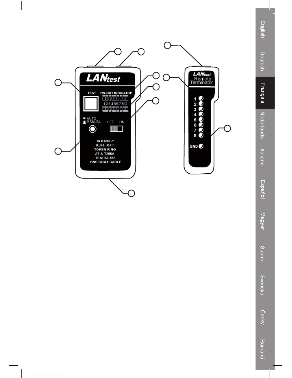
Unité
principale
Unité
distante
1) Prise RJ45
2) Prise RJ45
3) Affi chage à LED pour l'extrémité d'émission (prise 1)
4) Affi chage à LED pour l'extrémité de réception (prise 2)
5) Interrupteur
6) Commutateur de mode de balayage à LED
7) Commutateur de test pour balayage manuel
8) Prise RJ45
9) Affi chage à LED pour l'extrémité de réception (idem prise 2)
10) LED de mise à la terre pour l'extrémité de réception
11) Compartiment à piles (bloc 9 V)
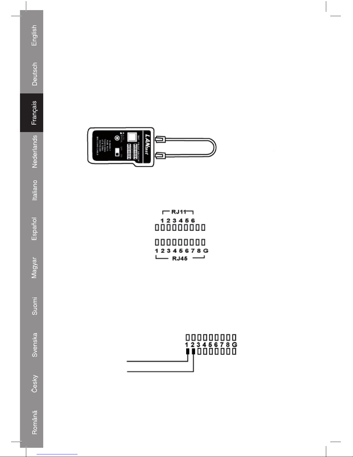
Fonctionnement et raccordement :
Test de boucle de retour
1) Test de câble 10Base-T.
• branchez une extrémité du câble à tester dans la prise d'émission RJ45 (marquée par
“”) et l'autre extrémité du câble à tester dans la prise de réception RJ45.
7
6
11
1
8
9
10
2
3
4
5
Page 16
16
• Activez l'alimentation. En mode automatique, les LED s'allument en séquence pour
indiquer l'état du câble. En mode manuel, la première LED s'allume pour indiquer
l'état du premier fi l. Appuyez sur un bouton de l'unité distante pour continuer le test du
prochain fi l.
• Placez le commutateur Auto/Manuel sur le mode de balayage Auto ou Manuel en
appuyant dessus.
• Lorsque le fi l est bon, la LED supérieure et la LED inférieure s'allument en même
temps.
Test de boucle de
retour
2) Test de câble modulaire
• Veuillez suivre les procédures du test de câble 10Base-T. L'affi chage à LED doit
cependant être identique à l'image suivante.
3) Test de câble 10Base-2
• Branchez les 2 câbles adaptateurs BNC joints sur les deux prises RJ45, puis branchez
le câble à tester sur les deux extrémités de câble adaptateurs BNC.
• Consultez le test de câble 10Base-T pour le reste des procédures.
Note : la broche centrale du BNC doit être lue sur la LED 1 et la broche de blindage du
BNC doit être lue sur la LED 2 (voir image ci-dessous)
BROCHE
CENTRALE BNC
BLINDAGE BNC
Note 2 : Puisque le câble 10Base-2 ne possède que 2 fi ls, nous vous conseillons de lire
le résultat du balayage LED en mode manuel.
Page 17
17
Test à distance
• Branchez une extrémité du câble à tester dans la prise d'émission RJ45 (marquée par
“”) de l'unité principale et l'extrémité du câble à la prise de réception RJ45 de l'unité
distante. Si le câble à tester est déjà installé sur le panneau de connexion ou la plaque
murale, vous pouvez utiliser le câble adaptateur pour résoudre le problème de genre du
connecteur.
• Passez en mode automatique lorsque vous effectuez ce test seul. De cette manière, le
testeur effectuera automatiquement le test de tous les fi ls à l'intérieur du câble, sans
nécessiter l'appui sur les boutons de l'unité distante.
• Lisez le résultat du test sur l'affi chage à LED de l'unité distante.
Note : L'affi chage à LED indique les fi ls dans la même séquence en mode automatique
comme en mode manuel.
Test à distance
Panneau de
connexion
Panneau mural
Page 18
18
Résultat du test
1. Continuité
continuité sur la broche 2
2. Ouverture ouverture sur la broche 2
3. Court-circuit les broches 2 et 3 sont court-circuitées
4. Mauvais câblage les broches 3 et 6 sont mal câblées|
Consignes de sécurité :
N'exposez jamais l'appareil à l'eau ou à l'humidité.
Entretien :
Ne nettoyez qu'avec un chiffon sec. N'utilisez pas de solvants ou de produits abrasifs.
Garantie :
Aucune garantie ou responsabilité ne sera acceptée en cas de modifi cation et/ou
de transformation du produit ou en cas de dommages provoqués par une utilisation
incorrecte de l'appareil.
Généralités :
Le design et les caractéristiques techniques sont sujets à modifi cation sans notifi cation
préalable.
Tous les logos de marques et noms de produits sont des marques déposées ou
immatriculées dont leurs détenteurs sont titulaires et sont donc reconnus comme telles
dans ce document.
Attention :
Ce symbole fi gure sur l'appareil. Il signifi e que les produits électriques et
électroniques ne doivent pas être jetés avec les déchets domestiques. Le
système de collecte est différent pour ce genre de produits.
Copyright ©
Page 19
19
Déclaration de conformité
Nous,
Ned is B.V.
De Tweeling 28
5215MC ’s-Hertogenbosch
The Netherlands
Tél : 0031 73 599 1055
Couriel : info@nedis.com
Déclarons que le produit :
Nom : König Electronic
Modèle: CMP-RCT31
Description: Testeur de câble réseau
est conforme aux prescriptions des normes suivantes :
EMC: EN 61000-6-1:2001
EN 61000-6-3:2001 + A11:2004
suivant la directive 2004/108/CEE.
‘s-Hertogenbosch, 1er juillet 2008
Mme. J. Gilad
Directrice des Achats
Page 20
20
NEDERLANDS
Introductie:
Deze König kabeltester leest de correcte pinconfi guratie van verschillende LAN-kabels,
door het zendende deel en het ontvangende deel te vergelijken. Met de afstandseenheid
is het eenvoudig om bestaande kabels en verbindingen te testen. Ideaal om kabels te
testen die achter wanden of plafonds zijn aangebracht. Het is eenvoudig om de kabel te
controleren op continuïteit, op kortsluiting of op verwisseling.
Eigenschappen:
• U kunt de juiste pinconfi guratie van 10Base-T, 10Base-2 Ethernetkabel, RJ45/RJ11
modulaire kabels, 258A, TIA-568A/568B, Token Ring kabels enz. controleren.
• De status is eenvoudig afl eesbaar om de kabel op continuïteit, kortsluiting, open en
ontbrekende draden te controleren.
• Met de afstandseenheid is het eenvoudig om bestaande kabels en verbindingen te
testen die zijn aangebracht achter wanden en plafonds.
• Kan testen zonder aarding.
• Uitgerust met auto of handmatige scan.
Specifi caties:
• Zender
Aansluitingen: 2x RJ45
Aanduiding: LED
Schakelaar: aan/uit
Schakelaar: Auto/Manual (handmatig)
Schakelaar: Test
• Afstandseenheid
Aansluitingen: RJ45
Aanduiding: LED
• Voeding: 9 V Batterij (niet bijgesloten)
• Behuizing: Kunststof
Aansluitingen:
Page 21
21
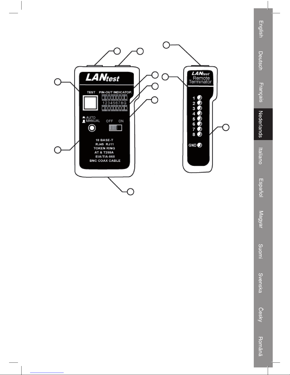
Hoofdeenheid Afstandeenheid
1) RJ45 contactbus
2) RJ45 contactbus
3) LED weergave voor broneinde (contactbus 1)
4) LED weergave voor ontvangsteinde (contactbus 2)
5) Aan-/uitschakelaar.
6) LED scan modus schakelaar
7) Test schakelaar voor handmatige scan
8) RJ45 contactbus
9) LED weergave voor ontvangsteinde (zelfde als contactbus 2)
10) Aarding LED voor ontvangsteinde
11) Batterijvak (9 V batterij)
Gebruik en aansluiting:
Lus test
1) 10Base-T kabeltest.
• Steek één eind van de te testen kabel in de bron RJ45 contactbus (gemarkeerd met
“”) en het andere eind van de te testen kabel in de ontvangende RJ45 contactbus.
7
6
11
1
8
9
10
2
3
4
5
Page 22

22
• Schuif de power switch (aan-/uitschakelaar) naar on. De leds in auto modus zullen
opeenvolgend gaan branden. Wanneer de eerste led zal gaan branden in manual mode
(handmatige modus), toont dit de status van het eerste draad. Druk op een knop op de
afstandseenheid om verder te gaan met de volgende draad.
• Stel de Auto/Manual schakelaar op Auto scan modus of Manual scan modus door de
Auto/Manual schakelaar te verschuiven.
• Wanneer een draad goed is, zullen de bovenste en onderste leds simultaan gaan
branden.
Lus test
2) Modulaire kabeltest
• Volg de procedure van de 10Base-T kabeltest. De led-weergave dient echter op de
hieronder weergegeven wijze te worden beoordeeld.
3) 10-2 Base-T kabeltest.
• Steek de 2 aangesloten BNC verloopkabels in beide RJ45 contactbussen, sluit dan de
te testen kabel aan op beide einden van de BNC verloopkabels.
• Voor de resterende procedures kunt u de 10Base-T kabeltest raadplegen.
NB: De centrale pin van BNC dient te worden gelezen op LED 1 en de afgeschermde pin
van BNC dient te worden gelezen op LED 2 (zie onderstaande afbeelding)
BNC CENTRALE PIN
BNC SHIELDING
NB 2: Omdat de 10Base-2 kabel maar 2 draden heeft, raden wij het aan om de resultaten
van de LED scan te lezen in de manual modus.
Page 23

23
Afstand test
• Steek één eind van de te testen kabel in de bron RJ45 contactbus (gemarkeerd met
“”) van de hoofdeenheid en het andere eind van de kabel in de ontvangende RJ45
contactbus van de ontvangende eenheid. Indien de te testen kabel reeds is aangesloten
op het patchpaneel of muurpaneel, kunt u de verloopkabel gebruiken om het stekker
probleem op te lossen.
• Schakel naar auto modus wanneer u deze test alleen gaat uitvoeren. Op deze manier
zal de tester automatisch alle draden binnen de kabel testen, zonder dat u op de
knoppen hoeft te drukken van de afstandseenheid.
• Lees de testresultaten van de led-weergave op de afstandseenheid.
NB: De led-weergave geeft de draden in dezelfde volgorde weer in de auto modus als in
de manuele modus.
Afstand test
Patchpaneel Wandcontactdoos
Page 24

24
Testresultaten
1. Continuïteit
pin 2 is constant
2. Open pin 2 is open
3. Kortsluiting pin 2 en pin 3 zijn kortgesloten
4. Ontbrekende draad pin 3 en pin 6 zijn foutief aangesloten
Veiligheidsvoorzorgsmaatregelen:
Stel het product niet bloot aan water of vocht.
Onderhoud:
Uitsluitend reinigen met een droge doek. Gebruik geen reinigingsmiddelen of
schuurmiddelen.
Garantie:
Voor wijzigingen en veranderingen aan het product of schade veroorzaakt door een
verkeerd gebruik van dit product, kan geen aansprakelijkheid worden geaccepteerd.
Tevens vervalt daardoor de garantie.
Algemeen:
Wijziging van ontwerp en specifi caties zonder voorafgaande mededeling onder
voorbehoud.
Alle logo's, merken en productnamen zijn handelsmerken of geregistreerde handelsmerken
van de respectievelijke eigenaren en worden hierbij als zodanig erkend.
Let op:
Dit product is voorzien van dit symbool. Dit symbool geeft aan dat afgedankte
elektrische en elektronische producten niet met het gewone huisafval
verwijderd mogen worden. Voor dit soort producten zijn er speciale
inzamelingspunten.
Copyright ©
Page 25

25
CONFORMITEITVERKLARING
Wij,
Nedis BV
De Tweeling 28
5215 MC ’s-Hertogenbosch
Nederland
Tel.: 0031 73 599 1055
E-mail: info@nedis.com
Verklaren dat het product:
Naam: König Electronic
Model: CMP-RCT31
Omschrijving: LAN-kabeltester
in overeenstemming met de volgende normen is
EMC: EN 61000-6-1:2001
EN 61000-6-3:2001 + A11:2004
Conform de bepalingen van richtlijn 2004/108/EG.
‘s-Hertogenbosch, 1 juli 2008
Mevr. J. Gilad
Directeur inkoop
Page 26

26
ITALIANO
Introduzione:
Questo tester per cavi König legge la corretta confi gurazione dei pin dei vari cavi LAN,
confrontando l'estremità trasmittente alla corrispondente estremità ricevente. Grazie
all'unità a distanza, è facile testare i cavi e i collegamenti esistenti. Ideale per testare i
fi li dietro pareti o soffi tti. È facile verifi care la continuità, l'apertura, il corto circuito e il
collegamento trasversale.
Caratteristiche:
• Può testare la corretta confi gurazione dei pin di cavo Ethernet 10 Base-T, 10Base-2,
cavi modulari RJ45/RJ11, cavi 258A, TIA-568A/568B e Token Ring, ecc.
• Rende facile leggere lo stato del cavo e verifi care la continuità, l'apertura, il corto circuito
del cavo e il cablaggio mancante.
• Grazie all'unità a distanza è facile testare i cavi e i collegamenti esistenti dietro pareti o
soffi tti.
• Può testare con messa a terra.
• Funzioni con scansione automatica o manuale.
Caratteristiche tecniche:
• Trasmettitore
Collegamenti: 2x RJ45
Indicatore: LED
Interruttore: ON/OFF
Interruttore: Automatico/Manuale
Interruttore: Test
• Unità a distanza
Collegamenti: RJ45
Indicatore: LED
• Alimentazione: Blocco 9 V (non incluso)
• Contenitore: Plastica
Collegamenti:
Page 27

27
Unità
principale
Unità a
distanza
1) Jack RJ45
2) Jack RJ45
3) Display LED per estremità sorgente (jack 1)
4) Display LED per estremità ricevente (jack 2)
5) Interruttore di alimentazione
6) Interruttore LED modalità scansione
7) Interruttore test per scansione manuale
8) Jack RJ45
9) Display LED per estremità ricevente (uguale a jack 2)
10) LED messa a terra per estremità ricevente
11) Vano batterie (9 V a blocco)
Funzionamento e collegamento:
Test loop di prova
1) Test cavo 10 Base-T.
• inserire una delle estremità del cavo da testare nella sorgente del jack RJ45
(contrassegnata con “”) e un'altra estremità del cavo da testare nei jack RJ45
riceventi.
7
6
11
1
8
9
10
2
3
4
5
Page 28

28
• Far scorrere l'interruttore su ON. In modalità automatica, i LED si illumineranno in
sequenza, per indicare lo stato del fi lo. In modalità manuale, il primo LED si illuminerà,
indicando lo stato del fi lo. Premere un pulsante sull'unità a distanza per continuare sul
fi lo successivo.
• Scegliere la modalità di scansione automatica o la modalità di scansione manuale
premendo l'interruttore automatico/manuale.
• Se il fi lo è in buone condizioni, i LED superiore e inferiore si illumineranno
contemporaneamente.
Test loop di prova
2) Test del cavo modulare
• Attenersi alle procedure del test del cavo 10 Base-T. Il display del LED deve comunque
essere letto secondo quanto illustrato di seguito.
3) Test cavo 10 Base-2
• Inserire i 2 cavi dell'adattatore BNC connessi su entrambi i jack RJ45, quindi collegare il
cavo da testare a entrambe le estremità dei cavi dell'adattatore BNC.
• Per le altre procedure, consultare il test del cavo 10 Base-T.
Nota: il pin centrale di BNC deve apparire sul LED 1 e il pin di schermatura di BNC deve
apparire sul LED 2 (vedere la fi gura più avanti).
PIN CENTRALE BNC
SCHERMATURA BNC
Nota 2: Poiché i cavi 10 Base-2 sono dotati di 2 soli fi li, si consiglia di leggere il risultato
della scansione LED con la modalità manuale.
Page 29

29
Test a distanza
• Inserire un'estremità del cavo da testare nel jack RJ45 sorgente (contrassegnato
con “”) dell'unità principale e l'estremità del cavo al jack RJ45 ricevente sull'unità a
distanza. Se il cavo da testare è già installato sul pannello di raccordo o sul quadro a
parete, è possibile usare il cavo dell'adattatore per risolvere il problema del genere di
connettore.
• Se si esegue solo questo test, passare in modalità automatica. In tal modo, il tester
eseguirà automaticamente il test su tutti i fi li interni al cavo, senza necessità di premere
i pulsanti sull'unità a distanza.
• Leggere il risultato del test sul display LED sull'unità remota.
Nota: Il display LED indica i fi li con la stessa sequenza in modalità automatica e in
modalità manuale.
Test a distanza
Pannello di
raccordo
Quadro a parete
Page 30

30
Risultato del test
1. Continuità
il pin 2 è continuo
2. Apertura il pin 2 è aperto
3. Corto il pin 2 e il pin 3 sono in corto
4. Filo
mancante
nel pin 3 e nel pin 6 mancano fi li
Precauzioni di sicurezza:
Non esporre il prodotto ad acqua o umidità.
Manutenzione:
Pulire solo con un panno asciutto. Non utilizzare solventi detergenti o abrasivi.
Garanzia:
Non sarà accettata alcuna garanzia o responsabilità in relazione a cambiamenti e
modifi che del prodotto o a danni determinati dall'uso non corretto del prodotto stesso.
Generalità
Il design e le caratteristiche tecniche sono soggetti a modifi ca senza necessità di
preavviso.
Tutti i marchi a logo e i nomi di prodotto sono marchi commerciali o registrati dei rispettivi
titolari e sono qui riconosciuti come tali.
Attenzione:
Il prodotto è contrassegnato con questo simbolo, con il quale si indica che i
prodotti elettrici ed elettronici usati non devono essere gettati insieme ai rifi uti
domestici. Per questi prodotti esiste un sistema di raccolta differenziata.
Copyright ©
Page 31

31
DICHIARAZIONE DI CONFORMITÀ
Questa società,
Ned is B.V.
De Tweeling 28
5215MC ’s-Hertogenbosch
Paesi Bassi
Tel.: 0031 73 599 1055
Email: info@nedis.com
Dichiara che il prodotto:
Nome: König Electronic
Modello: CMP-RCT31
Descrizione: Tester cavi LAN
è conforme ai seguenti standard:
EMC: EN 61000-6-1:2001
EN 61000-6-3:2001 + A11:2004
Secondo le disposizioni della direttiva 2004/108/CE.
‘s-Hertogenbosch, 1 luglio 2008
Sig.ra J. Gilad
Direttore agli acquisti
Page 32

32
ESPAÑOL
Introducción:
Este probador de cable de König lee la confi guración de la clavija correcta en distintos
cables LAN, comparando el extremo de transmisión con el extremo correspondiente
de recepción. Gracias a la unidad remota, es fácil probar los cables y las conexiones
existentes. Ideal para probar cables tras paredes o techos. Es fácil de comprobar la
continuidad del cable, la apertura, los cortes y las conexiones cruzadas.
Características:
• Puede probar la correcta confi guración de clavijas del cable Ethernet 10Base-T,
10Base-2, los cables modulares RJ45/RJ11 el cable 258A, TIA-568A/568B y el cable
Token Ring.
• Fácil de leer el estado del cable y comprobar la continuidad del cable, la apertura, los
cortes y los cables que falten.
• Con la unidad remota, es fácil probar los cables y conexiones existentes que se
esconden tras las paredes y techos.
• Puede probar con puesta a tierra.
• Funciones con búsqueda automática o manual.
Especifi caciones:
• Transmisor:
Conexiones: 2x RJ45
Indicación: LED
Interruptor: "ON/OFF" (ACTIVADO/DESACTIVADO)
Interruptor: Automático/Manual
Interruptor: Prueba
• Unidad remota
Conexiones: RJ45
Indicación: LED
• Potencia: Bloque de 9 V (no incluido)
• Carcasa: Plástico
Conexiones:
Page 33

33
Unidad
central
Unidad
remota
1) Toma de RJ45
2) Toma de RJ45
3) Pantalla LED para el extremo de fuente (toma 1)
4) Pantalla LED para el extremo de recepción (toma 2)
5) Interruptor de alimentación
6) Interruptor en modo de búsqueda LED
7) Interruptor de prueba para la búsqueda manual
8) Toma de RJ45
9) Pantalla LED para el extremo de recepción (igual que la toma 2)
10) LED de tierra para el extremo de recepción
11) Compartimento de pilas (bloque de 9 V)
Funcionamiento y conexión:
Prueba de retorno de ciclo
1) Prueba de cable 10Base-T.
• Conecte un extremo del cable a probar en la fuente de la toma RJ45
(marcado con “”) y el otro extremo del cable a probar en las tomas de recepción
RJ45.
7
6
11
1
8
9
10
2
3
4
5
Page 34

34
• Ponga el interruptor en posición de encendido. Cuando esté en modo automático, las
LED se encenderán en secuencia para indicar el estado del cable. Cuando esté en
modo manual, la primera LED se encenderá, mostrándole el estado del primer cable.
Pulse un botón de la unidad remota para seguir con el siguiente cable.
• Elija el interruptor automático/manual para el modo de búsqueda automático o manual
pulsando el interruptor de automático/manual.
• Cuando un cable es adecuado, la LED superior e inferior se encenderán a la vez.
Prueba de retorno
de ciclo
2) Prueba del cable modular
• Por favor, siga los procedimientos de la prueba del cable 10Base-T. No obstante, la
pantalla LED deberá indicarse tal y como se muestra a continuación.
3) Prueba de cable 10-Base-2.
• Conecte los 2 cables del adaptador BNC en ambas tomas RJ45, a continuación,
conecte el cable a probar a ambos extremos de los cables del adaptador BNC.
• Para los siguientes procedimientos, podrá acudir a la prueba del cable 10Base-T.
Nota: la clavija central del BNC deberá mostrarse en la LED 1 y la clavija de cubierta de
BNC deberá leerse en la LED 2 (véase la imagen indicada a continuación)
CLAVIJA CENTRAL
CUBIERTA BNC
Nota 2: Como el cable 10Base-2 tan sólo tiene dos cables, le sugerimos que lea el
resultado de la búsqueda LED mediante el modo manual.
Page 35

35
Prueba remota
• Conecte uno de los extremos del cable a probar en la fuente de la toma RJ45 (marcada
con “”) de la unidad principal y el extremo del cable de la toma de recepción RJ45 de
la unidad remota. Si el cable a probar ya está instalado en el panel de parches o en una
pared plana, podrá utilizar el cable del adaptador para resolver el problema del tipo de
conector.
• Pase al modo automático cuando esté realizando la prueba por sí sólo. De esta forma,
el probador probará automáticamente todos los cables dentro del cable, sin que deba
pulsar los botones de la unidad remota.
• Leal el resultado de la prueba a partir de la pantalla LED de la unidad remota.
Nota: La pantalla LED indica los cables en la misma secuencia en el modo automático
que en el manual.
Prueba remota
Panel de parche Panel de pared
Page 36

36
Resultado de prueba
1. Continuidad
la clavija 2 es continua
2. Abierto la clavija 2 está abierta
3. Corto la clavija 2 y la clavija 3 están cortadas
4. Falta cable la clavija 3 y la clavija 6 carecen de
cableado|
Medidas de seguridad:
No exponga el producto al agua ni a la humedad.
Mantenimiento:
Limpie sólo con un paño seco. No utilice disolventes ni productos de limpieza agresivos.
Garantía:
No se aceptará ninguna garantía o responsabilidad derivada de cualquier cambio o
modifi caciones realizadas al producto o daños provocados por un uso incorrecto del
presente producto.
General:
Las ilustraciones y las especifi caciones podrán sufrir cambios sin previo aviso.
Todas las marcas de los logotipos y los nombres de productos constituyen patentes o
marcas registradas de sus titulares correspondientes, reconocidos como tal.
Cuidado:
Este producto está señalizado con este símbolo. Esto signifi ca que los
productos eléctricos y electrónicos gastados no deberán mezclarse con los
desechos domésticos generales. Existen distintos sistemas de recogida
individuales para este tipo de productos.
Copyright ©
Page 37

37
Declaración de conformidad
La empresa infraescrita,
Ned is B.V.
De Tweeling 28
5215MC ’s-Hertogenbosch
Países Bajos
Tel.: 0031 73 599 1055
Email: info@nedis.com
declara que el producto:
Nombre: König Electronic
Modelo: CMP-RCT31
Descripción: Probador de cable LAN
se encuentra conforme a las siguientes normas:
EMC: EN 61000-6-1:2001
EN 61000-6-3:2001 + A11:2004
Conforme a las disposiciones de la directiva 2004/108/EEC.
‘s-Hertogenbosch, 01 de julio de 2008
D. J. Gilad
Director de compras
Page 38

38
MAGYAR NYELVŰ
A termék bemutatása:
Ez a kábelteszter leolvassa a LAN kábelek érintkezőkiosztását oly módon, hogy a kábel
küldő végét összehasonlítja a fogadó végével. A remote unit (távoli egység) segítségével
a kábelek és csatlakozások könnyen tesztelhetők. Falba vagy mennyezetbe ágyazott
vezetékek teszteléséhez ideális. Könnyen ellenőrizhető a kábel folytonossága, a
szakadások, zárlatok, átkötések.
A készülék tulajdonságai:
• A 10Base-T, 10Base-2 Ethernet kábelek, RJ45/RJ11 moduláris kábelek, 258A, TIA568A/568B, Token Ring kábelek stb. érintkezőkiosztásának tesztelésére alkalmas.
• Könnyen leolvassa a kábel állapotát, ellenőrzi folytonosságát, a szakadásokat,
zárlatokat és hibás bekötéseket.
• A remote unit (távoli egység) segítségével könnyen tesztelhetők a falba vagy
mennyezetbe ágyazott kábelek és csatlakozások.
• Földeléssel képes tesztelni.
• Automatikus vagy manuális letapogatással működik.
Műszaki jellemzők:
• Adó
Csatlakozások: 2 db RJ45
Kijelzés: LED
Kapcsoló: On/Off (Be/Ki)
Kapcsoló: Auto/Manual (Automatikus/Manuális)
Kapcsoló: Teszt
• Remote unit (távoli egység)
Csatlakozások: RJ45
Kijelzés: LED
• Áramforrás: 9 V blokk (nem tartozék)
• Készülékház: Műanyag
Csatlakozások:
Page 39

39
Master
egység
Távoli
egység
1) RJ45 jack-csatlakozó
2) RJ45 jack-csatlakozó
3) LED kijelző a küldő véghez (jack-csatlakozó 1)
4) LED kijelző a fogadó véghez (jack-csatlakozó 2)
5) Be- és kikapcsoló
6) Letapogatási mód kapcsoló LED-je
7) Tesztkapcsoló manuális letapogatáshoz
8) RJ45 jack-csatlakozó
9) LED kijelző a fogadó véghez (ugyananaz mint jack-csatlakozó 2)
10) Földelés LED a fogadó véghez
11) Teleptartó rekesz (9 V blokk)
Kezelés és csatlakoztatás:
Vizsgálóhurok
1) 10Base-T kábel tesztelése.
• a tesztelt kábel egyik végét dugaszolja a (“” jelzésű) küldő RJ45 jack-csatlakozóra, a
tesztelt kábel másik végét pedig a fogadó RJ45 jack-csatlakozókra.
7
6
11
1
8
9
10
2
3
4
5
Page 40

40
• Kapcsolja be a készüléket a be- és kikapcsolóval. Automatikus módban a LED-ek
egymás után kigyulladva jelzik a vezeték állapotát. Manuális módban először az első
LED gyullad ki, és az első vezeték állapotát jelzi. A remote unit (távoli egység) egyik
gombjának megnyomásával léphet tovább a következő vezetékhez.
• Az Auto/Manual kapcsolót lenyomva állítsa a készüléket automatikus vagy manuális
letapogató módba.
• Ha a vezeték rendben van, a felső és az alsó LED egyidejűleg kezd világítani.
Vizsgálóhurok
2) Moduláris kábel tesztelése
• Végezze el a 10Base-T kábel tesztelésénél megismert eljárást. A LED kijelzőt viszont
az alábbi ábra szerint kell leolvasni.
3) 10Base-2 kábel tesztelése
• Dugaszolja a 2 mellékelt BNC adapterkábelt mindkét RJ45 jack-csatlakozóra, majd
csatlakoztassa a tesztelt kábelt a BNC adapterkábel mindkét végéhez.
• A többi eljárás a 10Base-T kábel tesztelésénél megismerttel azonos.
Megjegyzés: a BNC középső érintkezőjét az 1. LED-en, a BNC árnyékoló érintkezőjét a
2. LED-en kell leolvasni (lásd az alábbi ábrát).
BNC KÖZÉPSŐ
ÉRINTKEZŐ
BNC ÁRNYÉKOLÓ
Megjegyzés 2: Mivel a 10Base-2 kábelben csak 2 vezeték van, azt javasoljuk, hogy a
LED-en a manuális letapogatás eredményét olvassa le.
Page 41

41
Távoli teszt
• A tesztelt kábel egyik végét dugaszolja a master egység (“” jelzésű) küldő RJ45
jack-csatlakozójára, másik végét a távoli egység fogadó RJ45 jack-csatlakozójára.
Ha a tesztelt kábel már rögzítve van a kapcsolótáblához vagy fali csatlakozóhoz, az
adapterkábellel megoldhatja a külső/belső csatlakozó problémáját.
• Kapcsoljon automatikus módra, ha a tesztet egyedül végzi. A teszter ilyenkor
automatikusan bevizsgálja a kábel összes vezetékét, és nem kell a távoli egység
gombjait nyomni.
• A teszt eredményét olvassa le a távoli egység LED kijelzőjéről.
Megjegyzés: A LED kijelző a vezetékeket mind automatikus mind manuális módban
ugyanabban a sorrendben jelzi.
Távoli teszt
Kapcsolótábla Fali csatlakozó
Page 42

42
A teszt eredménye
1. Folytonosság
a 2-es érintkező folytonos
2. Szakadás a 2-es érintkezőnél szakadás van
3. Zárlat a 2-es és 3-as érintkező zárlatos
4. Hibás bekötés a 3-as és 6-os érintkező hibásan van
bekötve
Biztonsági óvintézkedések:
Víztől és a nedvességtől óvja a terméket.
Karbantartás:
Csak száraz ronggyal tisztítsa. Tisztító- és súrolószereket ne használjon.
Jótállás:
Nem vállalunk felelősséget és jótállást, ha a meghibásodás a készüléken végzett
változtatás vagy módosítás következménye, vagy helytelen használat miatt a készülék
megrongálódott.
Általános tudnivalók:
A kivitel és a műszaki adatok előzetes értesítés nélkül is módosulhatnak.
Minden logó, terméknév és márkanév a tulajdonosának márkaneve vagy bejegyzett
márkaneve, és azokat ennek tiszteletben tartásával említjük.
Figyelem:
Ezt a terméket ezzel a jelöléssel láttuk el. Azt jelenti, hogy az elhasznált
elektromos és elektronikus készülékek nem keverhetők az általános háztartási
hulladék közé. Begyűjtésüket külön begyűjtő létesítmények végzik.
Copyright ©
Page 43

43
Megfelelőségi nyilatkozat
Mi,
a Nedis B.V. vállalat, cím:
De Tweeling 28
5215MC ’s-Hertogenbosch
Hollandia
Tel.: 0031 73 599 1055
E-mail: info@nedis.com
Kijelentjük, hogy a termék, amelynek:
Neve: König Electronic
Típusa: CMP-RCT31
Megnevezése: LAN kábelteszter
Megfelel az alábbi szabványoknak:
EMC (Elektromágneses összeférhetőségre vonatkozó irányelv):
EN 61000-6-1:2001
EN 61000-6-3:2001 + A11:2004
A 2004/108/EK irányelv előírásainak megfelelően.
‘s-Hertogenbosch, 2008. július 1.
Mrs. J. Gilad
Értékesítési igazgató
Megfelelőségi nyilatkozat.
Egyetértek és elfogadom a Nedis B.V. Hollandia által adott nyilakozatot.
Jacob Gilad
HQ-Nedis kft.
ügyvezető igazgató
Page 44

44
SUOMI
Johdanto:
Tämä König kaapelin testaaja lukee eri LAN-kaapelien oikean piikkikokoonpanon
vertaamalla lähetyspäätä vastaavaan vastaanottavaan päähän. Kaukoyksiköllä on helppo
testata olemassa olevia kaapeleita ja kytkentöjä. Ihanteellinen ratkaisu seinien tai kattojen
sisällä olevien johtojen testaukseen. Kaapelin jatkuvuus, avoin, lyhyt ja ristikytkentä on
helppo tarkistaa.
Ominaisuudet:
• Voi testata 10Base-T, 10Base-2 Ethernet-kaapelin, RJ45/RJ11 modulaarisien kaapelien,
258A, TIA-568A/568B ja Token Ring -kaapelin jne. oikean piikkikokoonpanon.
• Helposti luettava kaapelitila ja kaapelin jatkuvuus, avoin, lyhyt ja puuttuva johdotus.
• Kaukoyksikön ansiosta olemassa olevien seinän tai katon sisällä olevien kaapelien ja
kytkentöjen helppo testaus.
• Voi testata maadoituksella.
• Ominaisuuksiin kuuluu automaattinen ja manuaalinen selaus.
Tekniset tiedot:
• Lähetin
Kytkennät: 2x RJ45
Osoitin: LED
Kytkin: On/Off
Kytkin: Auto/Manual (Automaattinen/manuaalinen)
Kytkin: Testaus
• Kaukoyksikkö
Kytkennät: RJ45
Osoitin: LED
• Tehontarve: 9 V akku (ei kuulu pakkaukseen)
• Ulkokuori: Muovi
Kytkennät:
Page 45

45
Pääyksikkö Kaukoyksikkö
1) RJ45-liitin
2) RJ45-liitin
3) LED-näyttö lähdepäätä varten (liitin 1)
4) LED-näyttö vastaanottavaa päätä varten (liitin 2)
5) Virtakytkin
6) Selaustilan LED-kytkin
7) Testikytkin manuaalista selaus
8) RJ45-liitin
9) LED-näyttö vastaanottavaa päätä varten (vastaa liitintä 2)
10) Maadoituksen LED vastaanottavaa päätä varten
11) Paristokotelo (9 V akku)
Toiminta ja kytkentä:
Kaikutesti
1) 10Base-T -kaapelin testaus.
• Liitä testattavan kaapelin toinen pää lähteenä toimivaan RJ45-liittimeen (merkitty “”) ja
toinen testattavan kaapelin pää vastaanottaviin RJ45-liittimiin.
7
6
11
1
8
9
10
2
3
4
5
Page 46

46
• Liu'uta virtakytkin päälle. Audiotilassa LED-merkkivalot syttyvät vuoron perään ja ne
osoittavat johdon tilan. Manuaalisessa tilassa ensimmäinen LED-merkkivalo syttyy
ja osoittaa ensimmäisen johdon tilan. Paina kaukoyksikön painiketta jatkaaksesi
seuraavaan johtoon.
• Valitse Auto/Manual -kytkin vaitaksesi automaattisen Auto-selaustilan tai manuaalisen
Manual-selaustilan painamalla Auto/Manual-kytkintä.
• Kun johto on hyväksyttävä, laitteen ylä- ja alamerkkivalot syttyvät samanaikaisesti.
Kaikutesti
2) Modulaarinen kaapelitesti
• Noudata 10Base-T -kaapelitestin ohjeita. LED-näyttö tulee lukea kuitenkin seuraavasti.
3) 10Base-2 -kaapelitesti
• Liitä 2 liitettyä BNC-sovitinkaapelia molempiin RJ45-liittimiin, kytke testattava kaapeli
molempiin BNC-sovitinkaapelien päihin.
• Noudata tämän jälkeen 10Base-T-kaapelitestin ohjeita.
Huom: BNC-kaapelin keskuspiikki on luettava yksiköstä LED 1 ja BNC-kaapelin
suojapiikki tulee lukea yksiköstä LED 2 (katso kuva alla)
BNC-KESKUSPIIKKI
BNC-SUOJAUS
Huom 2: Koska 10Base-2 -kaapelissa on vain 2 johtoa, suosittelemme LED-valon
tuloksen lukemista manuaalista tilaa käyttäen.
Page 47

47
Kaukotesti
• Liitä testattavan kaapelin toinen pää pääyksikön lähteenä toimivaan RJ45-liittimeen
(merkitty “”) ja kaapelin pää kaukoyksikön vastaanottavaan RJ45-liittimeen. Jos
testattava kaapeli on jo asennettu ristikytkentätauluun tai seinälevyyn, voit ratkaista
liittimen sukupuoliongelman käyttämällä sovitinkaapelia.
• Kytke automaattitila päälle silloin, kun suoritat ainoastaan tämän testin. Tällöin
testaaja testaa automaattisesti kaikki kaapelin sisällä olevat johdot eikä kaukoyksikön
painikkeiden painaminen ole tarpeen.
• Lue testitulos kaukoyksikön LED-näytöltä.
Huom: LED-näyttö näyttää johdot samassa järjestyksessä sekä automaatti- että
manuaalisessa tilassa.
Kaukotesti
Ristikytkentätaulu Seinäpaneeli
Page 48

48
Testitulos
1. Jatkuvuus
piikki 2 on jatkuva
2. Avoin piikki 2 on avoin
3. Lyhyt piikki 2 ja 3 ovat lyhyitä
4. Puuttuva johto piikki 3 ja 6 ovat puuttuvia
Turvallisuuteen liittyvät varoitukset:
Älä altista tuotetta vedelle tai kosteudelle.
Huolto:
Puhdista ainoastaan kuivalla kankaalla. Älä käytä liuottimia tai hioma-aineita.
Takuu:
Takuu ja vastuuvelvollisuus mitätöityy, jos tuote vaurioituu siihen tehtyjen muutoksien tai
sen väärinkäytön takia.
Yleistä:
Muutoksia malliin ja teknisiin ominaisuuksiin voidaan tehdä ilmoituksetta.
Kaikki logot, merkit ja tuotenimet ovat niiden vastaavien omistajien tuotemerkkejä tai
rekisteröityjä tuotemerkkejä ja niitä on käsiteltävä sellaisina.
Huomio:
Tuote on varustettu tällä merkillä. Se merkitsee, ettei käytettyjä sähkö- tai
elektronisia tuotteita saa hävittää kotitalousjätteen mukana. Kyseisille tuotteille
on olemassa erillinen keräysjärjestelmä.
Copyright ©
Page 49

49
VAATIMUSTENMUKAISUUSVAKUUTUS
Me,
Ned is B.V.
De Tweeling 28
5215MC ’s-Hertogenbosch
Alankomaat
Puh: 0031 73 599 1055
Sähköposti: info@nedis.com
Vakuutamme, että tuote:
Nimi: König Electronic
Malli: CMP-RCT31
Kuvaus: LAN-kaapelin testaaja
Täyttää seuraavat standardit:
EMC: EN 61000-6-1:2001
EN 61000-6-3:2001 + A11:2004
Direktiivin 2004/108/ETY mukaisesti.
‘s-Hertogenbosch, 1. heinäkuuta 2008
Mrs. J. Gilad
Toim itusjo htaja
Page 50

50
SVENSKA
Inledning:
Denna König kabeltestare läser av stiftkonfi gurationen för olika LAN-kablar, genom att
jämföra den sändande sidan med motsvarande mottagarsida. Med fjärrenheten är det
lätt att testa existerande kablar och förbindelser. Ideal för att testa kablar som är dragna
inne i väggar eller tak. Det är mycket enkelt att kontrollera kablarnas kontinuitet, avbrott,
kortslutningar och korskopplingar.
Funktioner:
• Kan testa korrekt stiftkonfi guration för 10Base-T, 10Base-2 Ethernet kablar, RJ45/RJ11
modulära kablar, 258A, TIA-568A/568B och Token Ring kablar etc.
• Lätt att läsa av kabelns tillstånd och fastställa dess kontinuitet, avbrott, kortslutningar
och felkopplingar.
• Med fjärrenheten är det lätt att testa kablar som är dragna inne i väggar eller tak.
• Kan testa jordat.
• Automatisk eller manuell skanningsfunktion.
Specifi kationer:
• Sändare
Anslutningar: 2x RJ45
Indikator: LED
PÅ/AV PÅ/AV
Väljare: Auto/Manual
Kontakt: Test
• Fjärrenhet
Anslutningar: RJ45
Indikator: LED
• Strömkälla: 9 V blockbatteri (ingår ej)
• Förp: Plast
Anslutningar:
Page 51

51
Huvudenhet Fjärrenhet
1) RJ45 uttag
2) RJ45 uttag
3) LED display för sändande sida (uttag 1)
4) LED display för mottagande sida (uttag 2)
5) Strömbrytare
6) LED skanning lägesväljare
7) Testbrytare för manuell skanning
8) RJ45 uttag
9) LED display för mottagande sida (samma som uttag 2)
10) Jordnings-LED för mottagande sidan
11) Batterifack (9 V blockbatteri)
Användning och inkoppling:
Loopback test
1) 10Base-T kabel test.
• koppla ena ändan av kabeln som skall testas till det sändande RJ45 uttaget (märkt
med“”) och den andra ändan till det mottagande RJ45 uttaget.
7
6
11
1
8
9
10
2
3
4
5
Page 52

52
• Skjut strömbrytaren till on läget. I auto-läge kommer LED:arna att tändas i sekvens och
så indikera kabelns status. I manuellt läge kommer den första LED:en att tändas för att
visa dig den första ledningens status. Tryck på en knapp på fjärrenheten för att fortsätta
till nästa ledning.
• Välj automatisk eller manuell skanning med Auto/Manual väljaren.
• När en ledning är OK, kommer den övre och den undre LED:en att blinka samtidigt.
Loopback test
2) Test av modulära kablar
• Gör på samma sätt som i 10Base-T kabeltestet. LED displayen bör däremot läsas som
på bilden här nedan.
3) 10Base-2 kabeltest
• Koppla först de två medföljande BNC adapterkablarna till de båda RJ45 uttagen och
sedan kablarna som skall testas till BNC adapterkablarnas båda ändor.
• Gör sedan på samma sätt som vid 10Base-T kabeltestet.
OBS! BNC:s mittstift skall avläsas på LED 1 och skärmstiftet på LED 2 (se bild nedan)
BNC mittstift
BNC skärm
OBS 2: Eftersom 10Base-2 kabeln har bara 2 ledare, rekommenderar vi att du läser av
LED skanningens resultat i manuellt läge.
Page 53

53
Fjärrtest
• Koppla ena änden av kabeln som skall testas till huvudenhetens sändande RJ45 uttag
( märkt med “”) och den andra änden till fjärrenhetens mottagande RJ45 uttag. Om
kabeln som skall testas redan installerad i kabelcentralen eller väggplattan, kan du
använda adapterkabeln för att lösa kontakternas hona/hane problem.
• Koppla på auto-läget om du genomför det här testet ensam. På detta sätt kommer
testaren automatiskt att testa alla ledare inne i kabeln, utan att du behöver trycka på
fjärrenhetens knappar.
• Läs av testresultatet på fjärrenhetens LED display.
OBS! LED-displayen indikerar ledningarna i samma ordningsföljd både i automatiskt och
manuellt läge.
Fjärrtest
Kabelcentral Väggpanel
Page 54

54
Testresultat
1. Kontinuitet
stift 2 har kontakt
2. Avbrott stift 2 är öppet
3. kortslutning stift 2 och stift 3 är kortslutna
4. Felkoppling stift 3 och stift 6 är felkopplade
Säkerhetsanvisningar:
Utsätt inte produkten för vatten eller fukt.
Underhåll:
Rengör endast med torr trasa. Använd inga rengöringsmedel eller frätande medel.
Garanti:
Ingen garanti gäller vid några ändringar eller modifi eringar av produkten eller för skador
som har uppstått på grund av felaktig användning av denna produkt.
Allmänt:
Utseende och specifi kationer kan komma att ändras utan föregående meddelande.
Alla logotyper och produktnamn är varumärken eller registrerade varumärken som tillhör
sina ägare och är härmed erkända som sådana.
Observera!
Produkten är märkt med denna symbol. Det innebär att använda elektriska
eller elektroniska produkter inte får slängas bland vanliga hushållssopor. Det
fi nns särskilda återvinningssystem för dessa produkter.
Copyright ©
Page 55

55
ÖVERENSSTÄMMELSEFÖRKLARING
Vi,
Ned is B.V.
De Tweeling 28
5215MC ’s-Hertogenbosch
Holland
Tel.: 0031 73 599 1055
Email: info@nedis.com
Intygar att produkten:
Namn: König Electronic
Modell: CMP-RCT31
Beskrivning: LAN-kabeltestare
Överensstämmer med följande standarder:
EMC: EN 61000-6-1:2001
EN 61000-6-3:2001 + A11:2004
Uppfyller villkoren för direktiv 2004/108/EEC.
‘s-Hertogenbosch, 01 Juli 2008
Mrs. J. Gilad
Inköpschef
Page 56

56
ČESKY
Úvod:
Tento tester kabelů fi rmy König ověřuje správné zapojení kontaktů různých typů kabelů
LAN porovnáváním vysílacího a přijímacího konce kabelu. Pomocí vzdálené jednotky je
snadné testování existujících kabelů a propojení. Přístroj je ideální pro testování drátů ve
zdi nebo nad stropem. Usnadňuje ověření kontinuity kabelu, přerušení, zkrat a překřížení
propojení.
Funkce a popis:
• Tester ověřuje správné zapojení kontaktů na kabelech typu 10Base-T, 10Base-2
Ethernet, RJ45/RJ11 modulační kabely, 258A, TIA-568A/568B a přenosové kabely
uzavřené kruhové sítě („Token Ring“) apod.
• Snadné ověření stavu kabelu, kontinuity, přerušení, zkratu a chybného propojení.
• Pomocí vzdálené jednotky je snadné testování existujících kabelů a propojení za zdí
nebo nad stropem.
• Přístroj může testovat s uzemněním.
• Umožňuje automatické nebo manuální skenování.
Technická data:
• Vysílač:
Zapojení: 2x RJ45
Indikace: LED
Přepínač: „On/Off (Zapnuto/Vypnuto)“
Přepínač: Auto/Manual
Přepínač: Test
• Vzdálená jednotka
Zapojení: RJ45
Indikace: LED
• Napájení: 9V baterie (není součástí dodávky)
• Skříňka: Plast
Zapojení:
Page 57

57
Hlavní
jednotka
Vzdálená
jednotka
1) Konektor RJ45
2) Konektor RJ45
3) LED displej pro zdrojový konec (jack 1)
4) LED displej pro přijímací konec (jack 2)
5) Hlavní vypínač
6) LED indikátor přepínače skenovacího režimu
7) Spínač testování při ručním skenování
8) Konektor RJ45
9) LED displej pro přijímací konec (stejný jako jack 2)
10) LED indikace uzemnění na přijímacím konci
11) Držák baterie 9 V
Obsluha a zapojení:
Test vratné smyčky
1. Test kabelu 10Base-T
• Zapojte jeden konec testovaného kabelu do zdrojového konektoru RJ45 (s označením
„“) a druhý konec testovaného kabelu zapojte do přijímacího konektoru RJ45.
7
6
11
1
8
9
10
2
3
4
5
Page 58

58
• Zapněte hlavní vypínač do polohy ON. V automatickém režimu testování se začnou
LED diody postupně rozsvěcovat a indikují stav jednotlivých vodičů v kabelu. V ručním
testovacím režimu se rozsvítí první LED dioda, indikující stav prvního vodiče. Stisknutím
tlačítka na jednotce testeru přejděte na kontrolu dalšího vodiče.
• Stiskem přepínače Auto/Manual můžete zvolit automatický nebo manuální režim
testování jednotlivých vodičů.
• Je-li vodič v pořádku, rozsvítí se současně horní a spodní LED dioda.
Test vratné
smyčky
2. Testování modulačního kabelu
• Postupujte stejně jako při testování kabelu 10Base-T. Ale v tomto případě vyhodnoťte
LED displej podle následujícího zobrazení:
3. Test kabelu 10Base-2
• Zapojte 2 přiložené kabelové adaptéry do obou konektorů RJ45 a pak připojte testovaný
kabel k oběma koncům kabelových BNC adaptérů.
• Dál postupujte stejně jako při testování kabelu 10Base-T.
Poznámka: Středový (živý) kontakt sledujte na diodě LED 1 a stínění v BNC konektoru
na LED 2 (viz následující obrázek).
STŘEDNÍ KONTAKT
BNC
STÍNĚNÍ BNC
Poznámka 2: Vzhledem k tomu, že kabel 10Base-2 má pouze 2 vodiče, doporučujeme
při jeho zkoušení sledovat výsledek na LED diodách v režimu ručního
testování.
Page 59

59
Dálkový test
• Zapojte jeden konec testovaného kabelu do zdrojového konektoru RJ45 (s označením
„“) na hlavní jednotce a druhý konec testovaného kabelu do přijímacího konektoru
RJ45 na vzdálené jednotce. Je-li testovaný kabel již zabudovaný do propojovacího
panelu nebo nástěnné zásuvky, pak problém s typem konektoru („samec“ nebo
„samička“) vyřešte kabelovou redukcí.
• Pokud provádíte test sám, přepněte do automatického režimu. Tímto způsobem tester
vyzkouší všechny vodiče v kabelu bez nutnosti stisknout tlačítka na vzdálené jednotce.
• Výsledky testu přečtěte z LED displeje na vzdálené jednotce.
Poznámka: LED displej indikuje vodiče ve stejné posloupnosti jak v automatickém, tak i
ručním módu.
Dálkový test
Propojovací panel Nástěnná zásuvka
Page 60

60
Výsledky testu
1. Propojení
kontakt 2 je propojen
2. Přerušení kontakt 2 není propojen
3. Zkrat kontakty 2 a 3 jsou zkratovány
4. Špatné propojení kontakty 3 a 6 jsou nesprávně
zapojeny
Bezpečnostní opatření:
Nevystavujte zařízení nadměrné vlhkosti nebo vodě.
Údržba:
K čištění používejte pouze suchý hadřík. Nepoužívejte rozpouštědla ani abrazivní
materiály.
Záruka:
Jakékoli změny, modifi kace nebo poškození zařízení v důsledku nesprávného zacházení
se zařízením ruší platnost záruční smlouvy.
Obecné upozornění:
Design a specifi kace výrobku mohou být změněny bez předchozího upozornění.
Všechna loga a názvy výrobků jsou obchodní značky nebo registrované obchodní značky
příslušných vlastníků a jsou chráněny příslušnými zákony.
Upozornění:
Tento výrobek je označen následujícím symbolem. To znamená, že s výrobkem
je nutné zacházet jako s nebezpečným elektrickým a elektronickým odpadem
a nelze jej po skončení životnosti vhazovat do běžného domácího odpadu. Pro
tento druh použitých nebo vyřazených výrobků jsou zřízena oddělená sběrná
místa.
Copyright © (Autorská práva)
Page 61

61
Prohlášení o shodě
Společnost
Ned is B.V.
De Tweeling 28
5215MC ’s-Hertogenbosch
Nizozemí
Tel.: 0031 73 599 1055
E-mail: info@nedis.com
prohlašuje, že výrobek:
Jméno: König Electronic
Model: CMP-RCT31
Popis: Tester kabelu LAN
splňuje následující normy:
Elektromagnetická kompatibilita:
EN 61000-6-1:2001
EN 61000-6-3:2001 + A11:2004
a odpovídá ustanovením směrnice 2004/108/EEC.
‘s-Hertogenbosch, 1. července 2008
Paní J. Gilad
Obchodní ředitelka
Page 62

62
ROMÂNĂ
Introducere:
Acest tester de cabluri König “citeşte” confi guraţia corectă a pinilor diferitelor cabluri LAN,
comparând capătul de transmitere cu capătul de recepţie corespunzător. Unitatea de
teledetecţie face posibilă testarea uşoară a cablurilor şi conexiunilor existente. Aparatul
este ideal pentru testarea cablurilor care se afl ă ascunse după pereţi sau plafoane.
Cu ajutorul acestui aparat, verifi cările legate de continuitatea cablului, de conexiunile
deschise, scurt-circuitate sau în cruce devin uşoare.
Caracteristici:
• Aparatul poate testa confi guraţia corectă a cablurilor Ethernet 10Base-T şi 10Base-2,
a cablurilor modulare RJ45/RJ11, precum şi a cablurilor 258A, TIA-568A/568B şi Token
Ring, etc.
• Se pot citi şi verifi ca cu uşurinţă: statutul cablului, continuitatea lui, conexiunile deschise,
se poate stabili dacă cablul este scurt-circuitat sau dacă lipseşte.
• Cu această unitate de teledetecţie se pot testa cu uşurinţă cablurile şi conexiunile
existente, dar ascunse după pereţi sau plafoane.
• Testarea se poate face şi cu pământare.
• Funcţiile includ scanarea automată şi scanarea manuală.
Specifi caţii tehnice:
• Transmiţător
Conexiuni: 2x RJ45
Indicarea rezultatelor: cu LED-uri
Comutator: On/Off (Pornit/Oprit)
Comutator: Auto/Manual
Comutator: Testare
• Unitate principală
Conexiuni: RJ45
Indicarea rezultatelor: cu LED-uri
• Alimentarea electrică: Bloc de baterii de 9 V (nefurnizat)
• Carcasă: Plastic
Conexiuni:
Page 63

63
Unitatea
principală
Unitatea de
teledetecţie
1) Jack RJ45
2) Jack RJ45
3) Display cu LED-uri pentru capătul sursă (jack 1)
4) Display cu LED-uri pentru capătul de recepţie (jack 2)
5) Comutator alimentare electică
6) LED-ul comutatorului modului de scanare
7) Comutatorul de testare de la scanarea manuală
8) Jack RJ45
9) Display cu LED-uri pentru capătul de recepţie (acelaşi ca şi jackul 2)
10) LED-ul pământării de la capătul de recepţie
11) Compartimentul bateriei (bloc de baterii de 9 V)
Utilizare şi conexiuni:
Test în buclă
1) Testarea unui cablu 10Base-T
• Introduceţi unul din capetele cablului care se doreşte a fi testat în mufa RJ45 care trimite
semnalul sursă (marcat cu “”), iar celălalt capăt în mufa RJ45, cea care primeşte
semnalul.
7
6
11
1
8
9
10
2
3
4
5
Page 64

64
• Porniţi aparatul prin culisarea butonului de alimentare electrică. Dacă aparatul se afl ă în
modul Auto, LED-urile se vor aprinde pe rând, pentru a indica starea cablului. În modul
manual se aprinde primul LED, indicând starea primului cablu. Apăsaţi un buton de pe
unitatea de teledetecţie, pentru a trece la cablul următor.
• Aşezaţi comutatorul Auto/Manual în modul de scanare Auto sau în modul Manual, prin
apăsarea butonului Auto/Manual.
• Dacă cablul testat este în ordine, LED-ul de sus şi de jos se vor aprinde şi vor arde în
mod simultan.
Test în buclă
2) Testarea unui cablu modular
• Vă rugăm să urmaţi procedurile prezentate deja la testarea cablului 10Base-T. Acum
însă afi şajul cu LED-uri trebuie interpretat ca în fi gura de mai jos.
3) Testarea unui cablu 10Base-2
• Conectaţi cele 2 cabluri ale adaptorului BNC la ambele jackuri RJ45, după care conectaţi
ambele capete ale cablului supus testării la capetele cablului adaptorului BNC.
• Pentru procedurile care au mai rămas de efectuat, puteţi să consultaţi şi testarea
cablului 10Base-T.
Observaţie: Pinul central al cablului BNC trebuie să fi e lizibil pe LED-ul 1, iar pinul de
ecranare al cablului BNC pe LED-ul 2 (vezi fi gura de mai jos)
PINUL CENTRAL AL
CABLULUI BNC
ECRANAREA CABLULUI BNC
Observaţia 2: Deoarece cablul 10Base-2 are doar 2 fi re, vă recomandăm să citiţi
rezultatele indicate de LED-uri după o scanare efectuată în mod manual.
Page 65

65
Testarea teledetecţiei
• Introduceţi unul dintre capetele cablului supus testării în jackul RJ45 de transmitere
semnal (marcat cu “”) al unităţii principale, iar capătul celălalt al cablului în jackul
RJ45 al unităţii de teledetecţie. Dacă cablul care urmează a fi supus testării este instalat
deja într-un panou de distribuţie sau pe un panou de perete, pentru a rezolva problema
tipului de conector puteţi folosi şi cablul adaptorului.
• La efectuarea acestui test, vă rugăm să comutaţi pe modul Auto. În acest mod testerul
va testa în mod automat toate conductoarele din cablu, fără a mai fi nevoie de apăsarea
butoanelor afl ate pe unitatea de teledetecţie.
• Citiţi rezultatul testului de pe afi şajul cu LED-uri al unităţii de teledetecţie.
Observaţie: Afi şajul cu LED-uri indică conductoarele în aceeaşi ordine şi în modul auto
şi în modul manual.
Testarea teledetecţiei
Panou de
distribuţie
Panou de perete
Page 66

66
Rezultatul testării
1. Continuitate
pinul 2 continuă
2. Deschidere pinul 2 este deschis
3. Scurt-circuit pinul 2 şi pinul 3 fac scurt-circuit
4. Conductor lipsă pinul 3 şi pinul 6 sunt conectate greşit
Măsuri de siguranţă:
Feriţi aparatul de apă şi de umezeală.
Întreţinere:
Curăţarea trebuie făcută cu o cârpă uscată. Nu folosiţi solvenţi sau agenţi de curăţare
abrazivi.
Garanţie:
Nu oferim nicio garanţie şi nu ne asumăm niciun fel de responsabilitate în cazul
schimbărilor sau modifi cărilor aduse acestui produs sau în cazul deteriorării cauzate de
utilizarea incorectă a produsului.
Generalităţi:
Designul şi specifi caţiile produsului pot fi modifi cate fără o notifi care prealabilă.
Toate siglele mărcilor şi denumirile produselor sunt mărci comerciale sau mărci comerciale
înregistrate ale proprietarilor de drept şi prin prezenta sunt recunoscute ca atare.
Atenţie:
Acest produs este marcat cu acest simbol. Acest lucru înseamnă că produsele
electrice şi electronice uzate nu trebuie aruncate în gunoiul menajer. Aceste
produse au un sistem separat de colectare.
Copyright ©
Page 67

67
Declaraţie de conformitate
Noi,
Ned is B.V.
De Tweeling 28
5215MC ’s-Hertogenbosch
Olanda
Tel.: 0031 73 599 1055
Email: info@nedis.com
Declarăm că acest produs:
Denumire: König Electronic
Model: CMP-RCT31
Descriere: Tester cablu LAN
Este în conformitate cu următoarele standarde:
EMC: EN 61000-6-1:2001
EN 61000-6-3:2001 +A11:2004
În conformitate cu prevederile directivei 2004/108/EC.
‘s-Hertogenbosch, 01.07.2008
J. Gilad
Director achiziţii
Page 68

68
 Loading...