

Page 1
ČeskySvenskaSuomiMagyar
Español
ItalianoNederlandsFrançaisDeutschEnglish
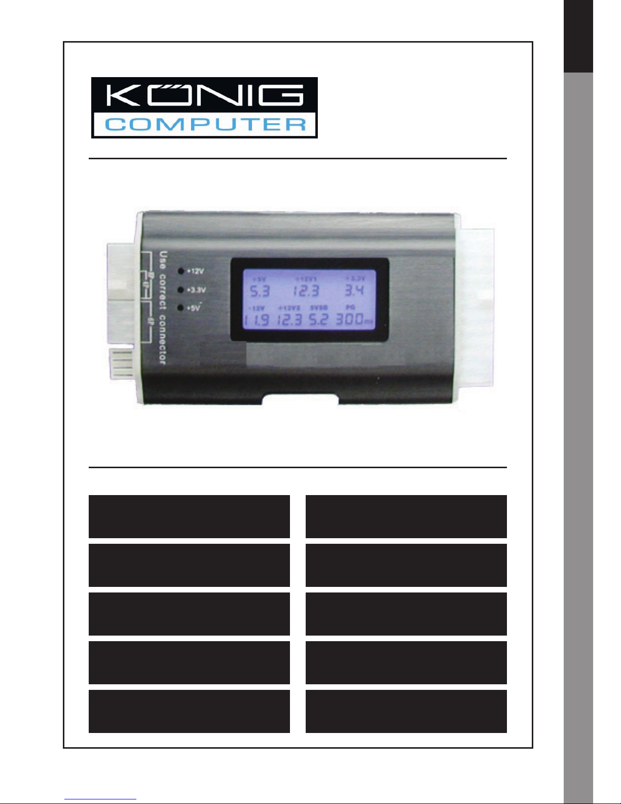
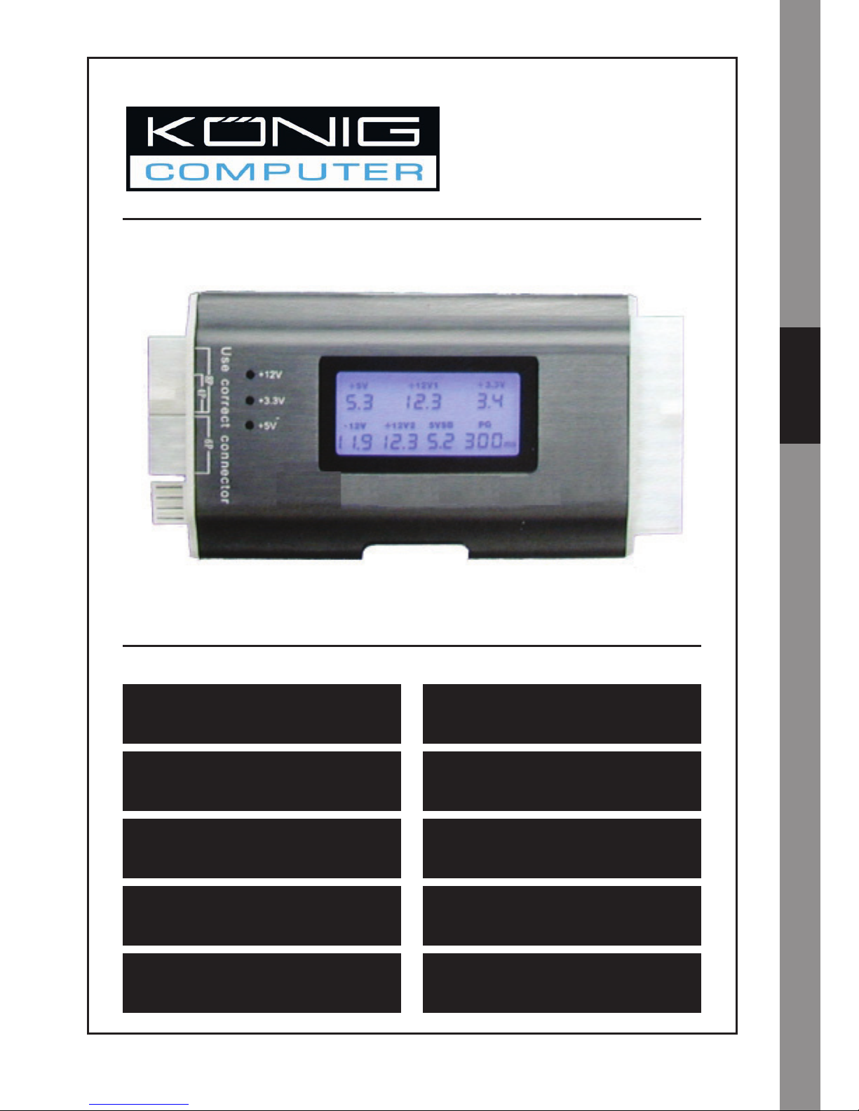
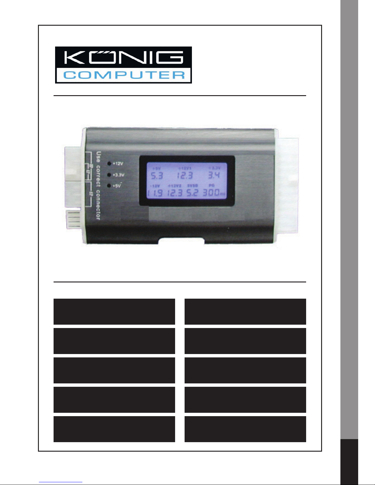
CMP-PSUTESTER5
Power supply tester
MANUAL
MODE D’EMPLOI
MANUALE
HASZNÁLATI ÚTMUTATÓ
BRUKSANVISNING
ANLEITUNG
GEBRUIKSAANWIJZING
MANUAL DE USO
KÄYTTÖOHJE
NÁVOD K POUŽITÍ
Page 2

Česky Svenska Suomi Magyar Español Italiano Français Deutsch English
1
Nederlands
A must have tool for anyone with PCs to test power supplies before putting them into
a PC. A bad power supply could damage system components if the voltages are not
correct, and do not assume that a brand new supply will always operate correctly.
Instructions:
BE AWARE: NEVER PLUG IN 2 CONNECTORS AT THE SAME TIME (NOT INCLUDING
THE 24/20 PIN CONNECTOR)
1. Plug in your 24/20 pin power supply connector to the tester.
2. Turn on your power supply.
3. LCD shows each voltage and P.G. value on the screen automatically and two beeps
can be heard.
4. The ATX power output connectors will be checked one by one. If the power output is
working properly the LED will come on, when it’s not working properly the LED light
will not come on.
5. Plug in the HDD and afterwards the Floppy connector and check the LED light
(+12V1 and +5V).
6. Plug in the SATA connector and check the LED light (+12V1, +5V and +3.3V).
7. Remove the connectors after checking (accept 24/20 PIN).
8. When abnormal voltage is detected it will not be displayed on the screen.
9. When no voltage is detected the screen will show “LL”.
10. When a voltage below minimum is detected it will show “LL”.
11. When a voltage higher than maximum is detected it will show “HH”.
12. When a voltage is detected which is lower or higher than the value shown in the
table below an alarm will sound.
13. When a P.G. value is detected which is lower than 100ms or higher than 900ms an
alarm will sound.
14. With any abnormality an alarm will sound and the related digit will blink.
Page 3
2
ČeskySvenskaSuomiMagyar
Español
ItalianoNederlandsFrançaisDeutschEnglish
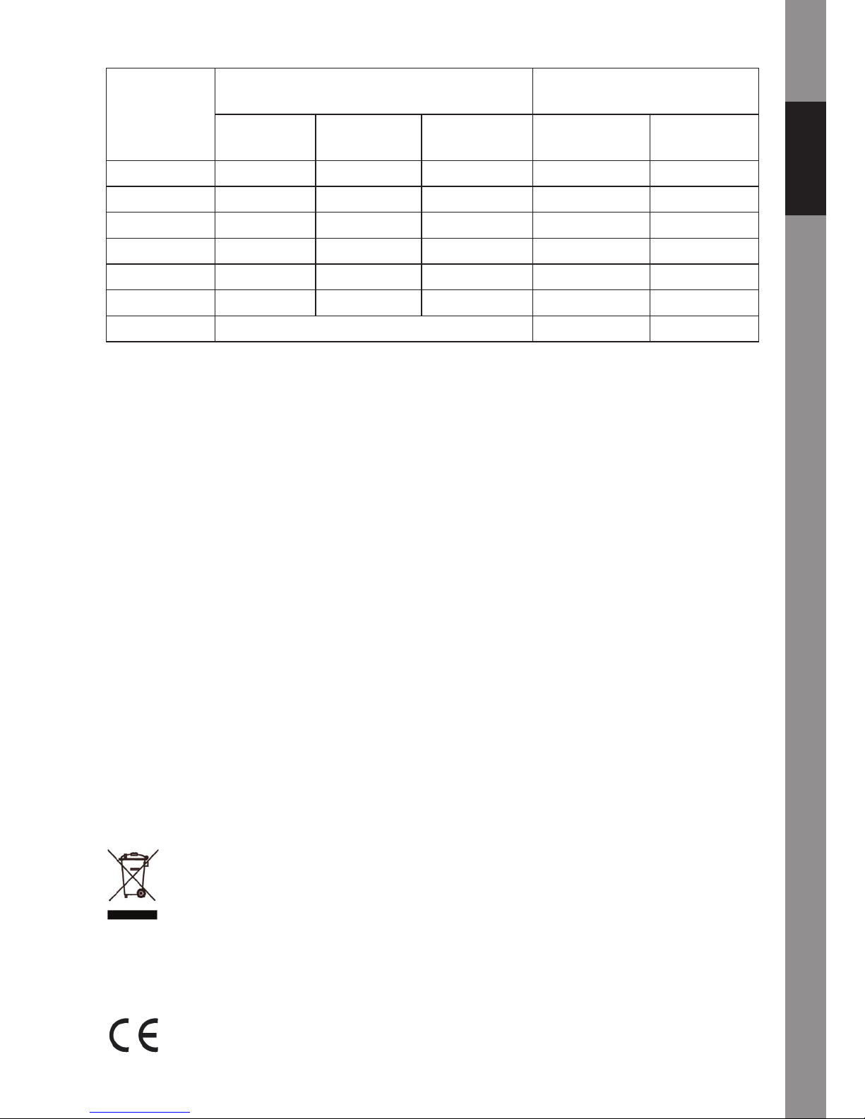
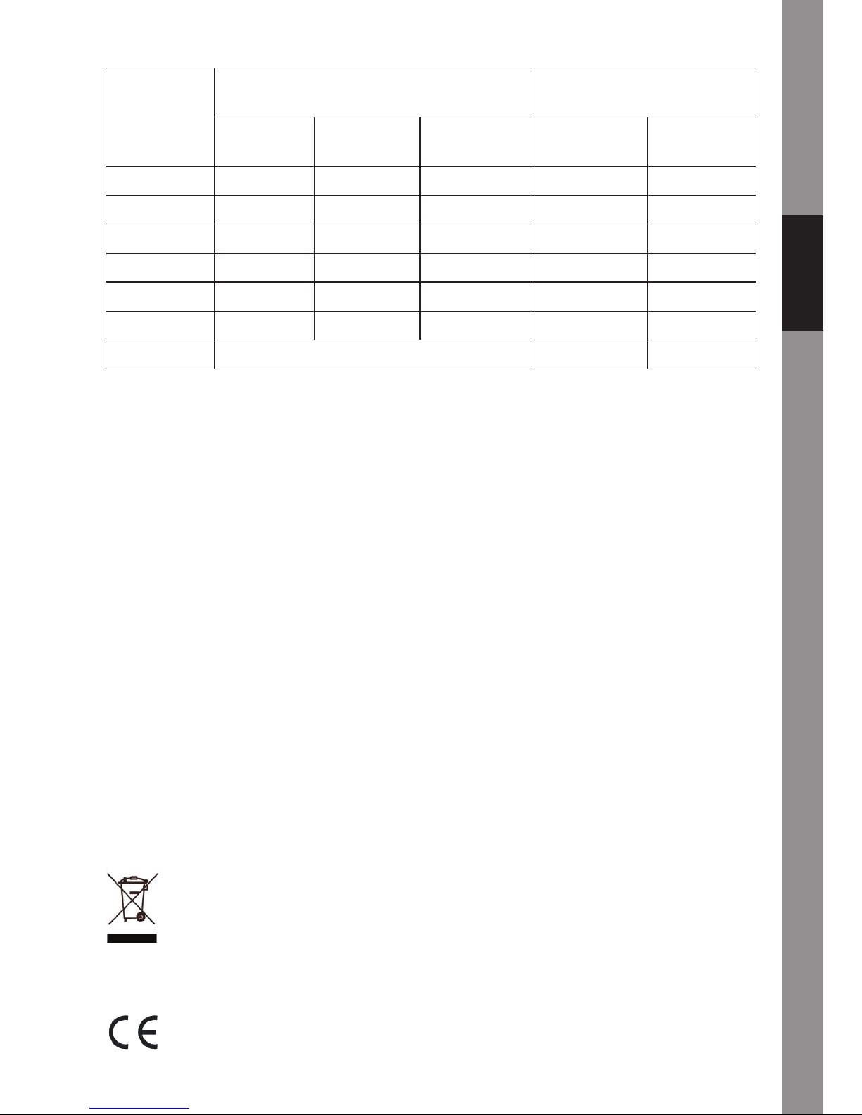
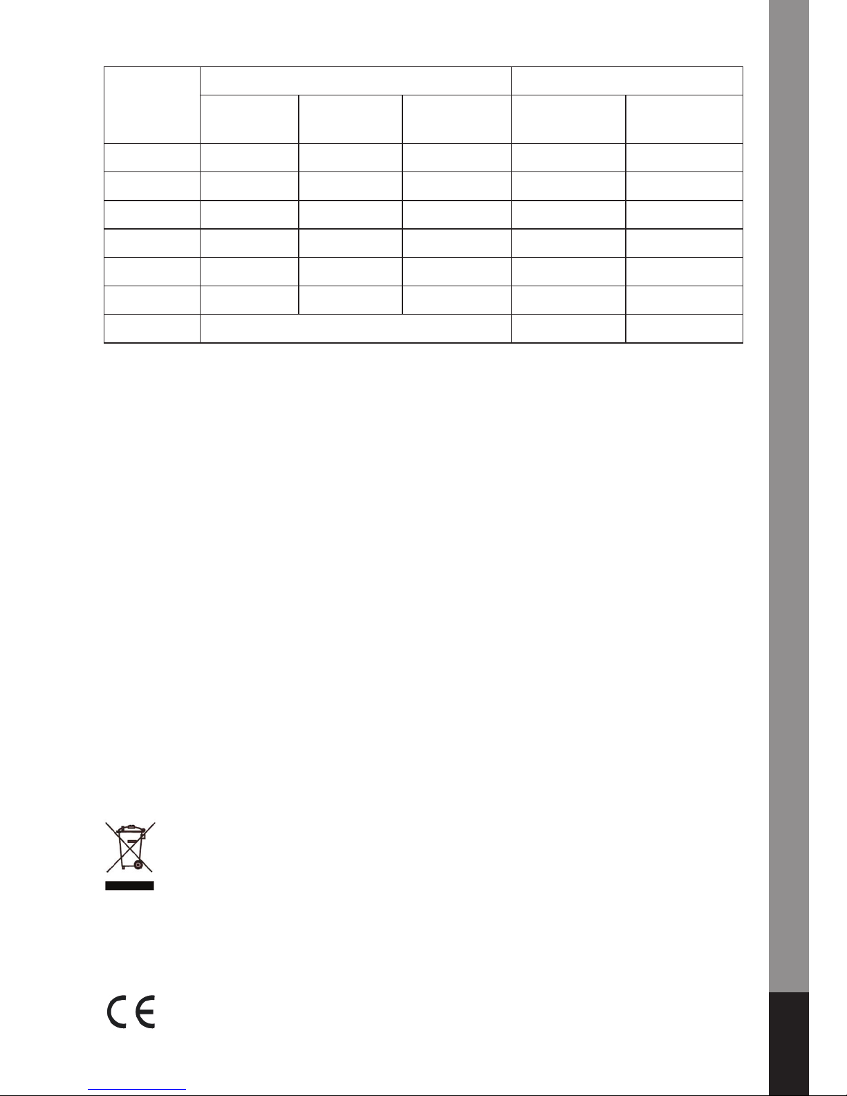
Normal Voltage range Display Voltage range
Lower (A) Higher (B) Min. ( C) Max. (D)
+5V 5V +4.75V +5.25V 4V 6.0V
-12V -12V -11V -13V -10V -14V
+12V1 12V 11V +13V 10V 14V
+12V2 12V 11V +13V 10V 14V
+3.3V 3.3V +3.14V +3.47V 2.0V 4.5V
+5VSB 5V +4.75V +5.25V 4.0V 6.0V
PG 0ms 990ms
Warning: This product is designed only for power supply output tests. Do not leave the
tester connected to the power supply unattended. It generates heat and could possibly
damage your power supply.
All brands and registered trademarks are property of the respective possessors.
Safety precautions:
To reduce risk of electric shock, this product should ONLY be opened by an authorized
technician when service is required. Disconnect the product from mains and other
equipment if a problem should occur. Do not expose the product to water or moisture.
Warranty:
No guarantee or liability can be accepted for any changes and modifi cations of the
product or damage caused due to incorrect use of this product.
General:
Designs and specifi cations are subject to change without notice.
All logos brands and product names are trademarks or registered trademarks of their
respective holders and are hereby recognized as such.
Attention:
This product is marked with this symbol. It means that used electrical and
electronic products should not be mixed with general household waste. There
is a separate collections system for these products.
Copyright ©
Page 4
ČeskySvenskaSuomiMagyar
Español
ItalianoNederlandsFrançaisDeutschEnglish
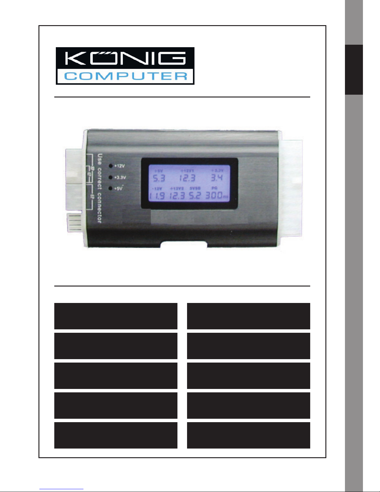
CMP-PSUTESTER5
StromversorgungsPrüfgerät
MANUAL
MODE D’EMPLOI
MANUALE
HASZNÁLATI ÚTMUTATÓ
BRUKSANVISNING
ANLEITUNG
GEBRUIKSAANWIJZING
MANUAL DE USO
KÄYTTÖOHJE
NÁVOD K POUŽITÍ
Page 5
Česky Svenska Suomi Magyar Español Italiano Français Deutsch English
1
Alle, die einen PC besitzen, müssen unbedingt ein Werkzeug haben, um die
Stromversorgungen zu überprüfen, bevor der PC an sie angeschlossen wird. Eine
schlechte Stromversorgung könnte die Systemkomponenten beschädigen, wenn
die Spannungen nicht richtig sind. Nehmen Sie nicht an, dass eine nagelneue
Stromversorgung immer richtig funktioniert.
Anweisungen:
ACHTEN SIE DARAUF: STECKEN SIE NIE 2 STECKER GLEICHZEITIG EIN (GILT
NICHT FÜR DEN 24/20-POLIGEN SRECKER)
1. Stecken Sie Ihren 24/20-poligen Stromversorgungsstecker in das Prüfgerät.
2. Schalten Sie Ihre Stromversorgung an.
3. Die LCD zeigt auf dem Bildschirm automatisch jede Spannung und den P.G.-Wert
an und es sind zwei Pieptöne zu hören.
4. Die ATX-Ausgangsstecker werden einer nach dem anderen überprüft. Wenn die
Ausgangsspannung richtig ist, leuchtet die LED, wenn sie nicht richtig ist, leuchtet
sie nicht.
5. Stecken Sie die Festplatte ein und danach den Floppy-Stecker und überprüfen Sie
die LED-Lampe (+12 V1 und +5 V).
6. Stecken Sie den SATA-Stecker ein und überprüfen Sie die LED-Lampe (+12 V1,
+5 V und +3,3 V).
7. Ziehen Sie die Stecker nach der Überprüfung ab (außer 24/20-polig).
8. Wenn eine unnormale Spannung gemessen wird, wird sie nicht auf dem Bildschirm
angezeigt.
9. Wenn keine Spannung gemessen wird, wird "LL" auf dem Bildschirm angezeigt.
10. Wenn eine Spannung unterhalb des Minimums gemessen wird, wird "LL"
angezeigt.
11. Wenn eine Spannung oberhalb des Maximums gemessen wird, wird "HH"
angezeigt.
12. Wenn eine Spannung gemessen wird, die niedriger oder höher als der in unten
aufgeführter Tabelle gezeigte Wert ist, ertönt ein Alarm.
13. Wenn ein P.G.-Wert gemessen wird, der kleiner als 100 msek. oder größer als 900
msek. ist, ertönt ein Alarm.
14. Bei jeder Abnormalität ertönt ein Alarm und die entsprechende Ziffer blinkt.
Page 6
2
ČeskySvenskaSuomiMagyar
Español
ItalianoNederlandsFrançaisDeutschEnglish
Normaler Spannungsbereich
Spannungsbereich
anzeigen
Niedriger
(A)
Höher (B) Min. ( C) Max. (D)
+5 V 5 V +4,75 V +5,25 V 4 V 6,0 V
-12 V -12 V -11 V -13 V -10 V -14 V
+12 V1 12 V 11 V +13 V 10 V 14 V
+12 V2 12 V 11 V +13 V 10 V 14 V
+3,3 V 3,3 V +3,14 V +3,47 V 2,0 V 4,5 V
+5 VSB 5 V +4,75 V +5,25 V 4,0 V 6,0 V
PG 0 ms 990 ms
Warnung: Dieses Produkt ist nur für Überprüfungen der Stromversorgungsausgänge
bestimmt. Lassen Sie das Prüfgerät nicht unbeaufsichtigt an der Stromversorgung
angeschlossen. Es erzeugt Wärme und könnte Ihre Stromversorgung beschädigen.
Alle Marken und eingetragenen Warenzeichen sind Eigentum ihrer jeweiligen Besitzer.
Sicherheitsvorkehrungen:
Um das Risiko eines elektrischen Schlags zu verringern, sollte dieses Produkt
AUSSCHLIESSLICH von einem autorisierten Techniker geöffnet werden, wenn eine
Wartung erforderlich ist. Trennen Sie das Produkt vom Stromnetz und anderen Geräten,
wenn ein Problem auftreten sollte. Sorgen Sie dafür, dass das Gerät nicht mit Wasser
oder Feuchtigkeit in Berührung kommt.
Garantie:
Es kann keine Garantie oder Haftung für irgendwelche Änderungen oder Modifi kationen
des Produkts oder für Schäden übernommen werden, die aufgrund einer nicht
ordnungsgemäßen Anwendung des Produkts entstanden sind.
Allgemein:
Konstruktionen und technische Daten können ohne vorherige Ankündigung geändert
werden.
Alle Logos, Marken und Produktnamen sind Warenzeichen oder registrierte Warenzeichen
ihrer jeweiligen Eigentümer und werden hiermit als solche anerkannt.
Achtung:
Dieses Produkt ist mit diesem Symbol gekennzeichnet. Es bedeutet, dass die
verwendeten elektrischen und elektronischen Produkte nicht im allgemeinen
Haushaltsmüll entsorgt werden dürfen. Für diese Produkte stehen gesonderte
Sammelsysteme zur Verfügung.
Copyright ©
Page 7
ČeskySvenskaSuomiMagyar
Español
ItalianoNederlandsFrançaisDeutschEnglish
CMP-PSUTESTER5
Testeur de bloc
d'alimentation
MANUAL
MODE D’EMPLOI
MANUALE
HASZNÁLATI ÚTMUTATÓ
BRUKSANVISNING
ANLEITUNG
GEBRUIKSAANWIJZING
MANUAL DE USO
KÄYTTÖOHJE
NÁVOD K POUŽITÍ
Page 8

Česky Svenska Suomi Magyar Español Italiano Français Deutsch English
1
Un must pour toute personne possédant un PC qui permet de tester les alimentations
électriques avant de les raccorder au PC. Une mauvaise alimentation électrique peut
endommager les composants du système si les tensions ne sont pas correctes sans
garantir qu'un nouveau bloc fonctionnera toujours correctement.
Instructions :
ATTENTION : NE BRANCHEZ JAMAIS 2 CONNECTEURS
1. Branchez votre connecteur d'alimentation 24/20 broches au testeur.
2. Allumez l‘alimentation électrique.
3. Le panneau affi che chaque tension et la valeur P.G automatiquement à l'écran et
deux bips retentissent.
4. Les connecteurs ATX sont testés un par un. Si la puissance de sortie est correcte la
LED s'allume et elle reste éteinte en cas de dysfonctionnement.
5. Branchez le connecteur du disque dur puis celui du Floppy et vérifi ez la LED (+12V1
et +5V).
6. Branchez le connecteur SATA et vérifi ez la LED (+12V1, +5V et +3.3V).
7. Retirez les connecteurs après vérifi cation (sauf le connecteur 24/20 broches).
8. En cas de tension anormale, elle n'est pas affi chée à l'écran.
9. Si aucune tension n'est détectée, l'écran indique “LL”.
10. Si la tension détectée est en dessous du minimum, l'écran indique “LL”.
11. Si la tension est supérieure au maximum, l'écran indique “HH”.
12. Si la tention détectée est inférieure ou supérieure à la valeur indiquée dans le
tableau ci-dessous, une alarme retentit.
13. Quand la valeur PG est inférieure à 100ms ou supérieure à 900ms, une alarme
retentit.
14. En cas d'anomalie, une alarme retentit et le chiffre correspondant clignote.
Page 9
2
ČeskySvenskaSuomiMagyar
Español
ItalianoNederlandsFrançaisDeutschEnglish
Gamme normale de tensions
Gamme de tensions
affi chée
Inférieure
(A)
Supérieure
(B)
Min. ( C) Max. (D)
+5V 5V +4.75V +5.25V 4V 6.0V
-12V -12V -11V -13V -10V -14V
+12V1 12V 11V +13V 10V 14V
+12V2 12V 11V +13V 10V 14V
+3.3V 3.3V +3.14V +3.47V 2.0V 4.5V
+5VSB 5V +4.75V +5.25V 4.0V 6.0V
PG 0ms 990ms
Attention : Ce produit n'est conçu que pour tester la sortie des blocs d'alimentation. Ne
laissez pas le testeur branché à l‘alimention électrique sans surveillance. La chaleur
générée pourrait endommager votre bloc d'alimentation.
Toutes les marques et marques déposées sont propriétés de leurs titulaires respectifs.
Consignes de sécurité :
Afi n de réduire les risques de chocs électriques, ce produit ne doit être ouvert QUE par
un technicien qualifi é agréé en cas de réparation. Débranchez l'appareil du secteur et
des autres équipements en cas de problème. N'exposez jamais l'appareil à l'eau ou à
l'humidité.
Garantie :
Aucune garantie ou responsabilité ne sera acceptée en cas de modifi cation et/ou
de transformation du produit ou en cas de dommages provoqués par une utilisation
incorrecte de l'appareil.
Généralités :
Le design et les caractéristiques techniques sont sujets à modifi cation sans notifi cation
préalable.
Tous les logos de marques et noms de produits sont des marques déposées ou
immatriculées dont leurs détenteurs sont titulaires et sont donc reconnues comme telles
dans ce document.
Attention :
Ce symbole fi gure sur l'appareil. Il signifi e que les produits électriques et
électroniques ne doivent pas être jetés avec les déchets domestiques.
Le système de collecte est différent pour ce genre de produits.
Copyright ©
Page 10
ČeskySvenskaSuomiMagyar
Español
ItalianoNederlandsFrançaisDeutschEnglish
CMP-PSUTESTER5
Stroomtoevoertester
MANUAL
MODE D’EMPLOI
MANUALE
HASZNÁLATI ÚTMUTATÓ
BRUKSANVISNING
ANLEITUNG
GEBRUIKSAANWIJZING
MANUAL DE USO
KÄYTTÖOHJE
NÁVOD K POUŽITÍ
Page 11

Česky Svenska Suomi Magyar Español Italiano Français Deutsch English
1
Nederlands
Een onmisbaar instrument voor mensen die met computers werken, zodat zij eerst de
voeding kunnen testen voordat de computer wordt aangesloten. Een slechte voeding
kan de systeemcomponenten beschadigen als het voltage onjuist is, bovendien moet
men er niet vanuit gaan dat een nieuwe voeding altijd goed werkt.
Instructies:
WAARSCHUWING: NOOIT 2 CONNECTOREN TEGELIJKERTIJD INSTEKEN (HEEFT
GEEN BETREKKING OP DE 24/20 PIN-CONNECTOR)
1. Koppel de 24/20 pin voedingconnector aan de tester.
2. Schakel de stroomvoorziening in.
3. De LCD geeft elke waarde van het voltage en de P.G. automatisch op het scherm
weer en twee pieptonen zijn hoorbaar.
4. De ATX-stroomafgifteconnectoren worden één-voor-één gecontroleerd. Als de
stroomafgifte op de juiste manier functioneert, zal de LED oplichten. Als de
stroomafgifte niet goed functioneert zal de LED niet oplichten.
5. Steek de HDD in en daarna de Floppy-connector en controleer de LED (+12V1 en
+5V.
6. Steek de SATA-connector in en controleer de LED (+12V1, +5V en +3.3V).
7. Verwijder de connectoren na de controle (behalve de 24/20 PIN).
8. Als een onjuiste voltage wordt gedetecteerd, wordt dit niet op het scherm
weergegeven.
9. Als er geen voltage wordt gedetecteerd, geeft het scherm “LL” weer.
10. Als een voltage onder het minimum wordt gedetecteerd, geeft het scherm “LL”
weer.
11. Als een voltage hoger dan het maximum wordt gedetecteerd, geeft het scherm
“HH”.
12. Als een voltage wordt gedetecteerd die lager of hoger is dan de waarde in de
onderstaande tabel, wordt een alarm weergegeven.
13. Als een P.G.-waarde wordt gedetecteerd die lager is dan 100 ms of hoger dan 900
ms wordt een alarm weergegeven.
14. Bij elke afwijking zal een alarm worden weergegeven en zal de betreffende LED
gaan knipperen.
Page 12
2
ČeskySvenskaSuomiMagyar
Español
ItalianoNederlandsFrançaisDeutschEnglish
Normale voltagebereik
Weergave van het
voltagebereik
Laag (A) Hoog (B) Min. ( C) Max. (D)
+5V 5V +4.75V +5.25V 4V 6.0V
-12V -12V -11V -13V -10V -14V
+12V1 12V 11V +13V 10V 14V
+12V2 12V 11V +13V 10V 14V
+3.3V 3.3V +3.14V +3.47V 2.0V 4.5V
+5VSB 5V +4.75V +5.25V 4.0V 6.0V
PG 0ms 990ms
Waarschuwing: Dit product is uitsluitend bestemd voor het testen van de stroomafgifte.
Nooit zonder toezicht de tester met aangesloten voeding achterlaten. Het kan hitte
opwekken en mogelijk tot schade aan de stroomtoevoer Ieiden.
Alle merken en geregistreerde handelsmerken zijn eigendom van de betreffende
eigenaren.
Veiligheidsvoorzorgsmaatregelen:
Wanneer service of reparatie noodzakelijk is, mag dit product UITSLUITEND door
een geautoriseerde technicus geopend worden; dit om de kans op het krijgen van een
elektrische schok te voorkomen. Als er een probleem optreedt, koppel het product dan
los van het lichtnet en van andere apparatuur. Stel het product niet bloot aan water of
vocht.
Garantie:
Voor wijzigingen en veranderingen aan het product of schade veroorzaakt door een
verkeerd gebruik van dit product, kan geen aansprakelijkheid worden geaccepteerd.
Tevens vervalt daardoor de garantie.
Algemeen:
Wijziging van ontwerp en specifi caties zonder voorafgaande mededeling onder
voorbehoud.
Alle logo's, merken en productnamen zijn handelsmerken of geregistreerde
handelsmerken van de respectievelijke eigenaren en worden hierbij als zodanig erkend.
Let op:
Dit product is voorzien van dit symbool. Dit symbool geeft aan dat afgedankte
elektrische en elektronische producten niet met het gewone huisafval verwijderd
mogen worden. Voor dit soort producten zijn er speciale inzamelingspunten.
Copyright ©
Page 13

ČeskySvenskaSuomiMagyar
Español
ItalianoNederlandsFrançaisDeutschEnglish
CMP-PSUTESTER5
Collaudatore di
alimentazione
MANUAL
MODE D’EMPLOI
MANUALE
HASZNÁLATI ÚTMUTATÓ
BRUKSANVISNING
ANLEITUNG
GEBRUIKSAANWIJZING
MANUAL DE USO
KÄYTTÖOHJE
NÁVOD K POUŽITÍ
Page 14

Česky Svenska Suomi Magyar Español Italiano Français Deutsch English
1
Uno strumento assolutamente necessario per chi possiede un PC e desidera testare le
alimentazioni prima di inserirle in un PC. Un'alimentazione guasta potrebbe danneggiare
i componenti di sistema se le tensioni non sono corrette, pertanto non partite dal
presupposto che un‘alimentazione nuova di zecca funzionerà sempre correttamente.
Istruzioni:
ATTENZIONE: MAI INSERIRE 2 CONNETTORI ALLO STESSO TEMPO (ESCLUSO IL
CONNETTORE DA 24/20 PIN)
1. Inserite il connettore di alimentazione da 24/20 pin nel collaudatore.
2. Attivate l'alimentazione.
3. Lo schermo a cristalli liquidi indica automaticamente ciascun voltaggio e valore P.G.
sullo schermo ed è possibile udire due squilli.
4. I connettori dell'uscita di alimentazione ATX verranno verifi cati ad uno ad uno. Se
l'uscita di alimentazione funziona correttamente il LED si illuminerà, quando non
funziona correttamente, la spia LED non si illuminerà.
5. Inserire il disco rigido e successivamente il connettore Floppy e verifi care la spia
LED (+12V1 and +5V).
6. Inserire il connettore SATA e verifi care la spia LED (+12V1, +5V and +3,3V).
7. Rimuovere i connettori dopo la verifi ca (accetta PIN da 24/20).
8. Quando viene rilevata una tensione anomala, essa non sarà visualizzata sullo
schermo.
9. Quando non viene rilevata alcuna tensione, lo schermo indicherà “LL”.
10. Quando viene rilevata una tensione al di sotto del valore minimo, lo schermo
indicherà “LL”.
11. Quando viene rilevata una tensione al di sopra del valore massimo, lo schermo
indicherà “HH”.
12. Quando viene rilevata una tensione che è inferiore o superiore al valore indicato
nella tabella sottostante, suonerà un allarme.
13. Quando viene rilevato un valore P.G. inferiore a 100ms o superiore a 900ms suonerà
un allarme.
14. Quando si verifi ca una qualsiasi anormalità, suonerà un allarme e la
corrispondente cifra lampeggerà.
Page 15

2
ČeskySvenskaSuomiMagyar
Español
ItalianoNederlandsFrançaisDeutschEnglish
Gamma di tensione normale
Display della gamma di
tensione
Inferiore (A)
Superiore
(B)
Min. ( C) Max. (D)
+5V 5V +4,75V +5,25V 4V 6,0V
-12V -12V -11V -13V -10V -14V
+12V1 12V 11V +13V 10V 14V
+12V2 12V 11V +13V 10V 14V
+3,3V 3,3V +3,14V +3,47V 2,0V 4,5V
+5VSB 5V +4,75V +5,25V 4,0V 6,0V
PG 0ms 990ms
Avvertenza: Questo prodotto è ideato solo per collaudi sulle uscite di alimentazione.
Non lasciate il collaudatore collegato all'alimentazione incustodito. Genera calore ed è
possibile che daneggi l'alimentazione.
Tutti i marchi e i marchi registrati sono di proprietà dei rispettivi proprietari.
Precauzioni di sicurezza:
Per ridurre il rischio di scosse elettriche, questo prodotto deve essere aperto
ESCLUSIVAMENTE da personale tecnico specializzato, se occorre assistenza. Se si
dovessero verifi care dei problemi, scollegare il prodotto dall'alimentazione di rete e da
ogni altra apparecchiatura. Non esporre il prodotto ad acqua o umidità.
Garanzia:
Non sarà accettata alcuna garanzia o responsabilità in relazione a cambiamenti
e modifi che del prodotto o a danni determinati dall'uso non corretto del prodotto stesso.
Generalità:
Il design e le caratteristiche tecniche sono soggetti a modifi ca senza necessità di
preavviso.
Tutti i marchi a loto e i nomi di prodotto sono marchi commerciali o registrati dei rispettivi
titolari e sono in questo documento riconosciuti come tali.
Attenzione:
Il prodotto è contrassegnato con questo simbolo, con il quale si indica che
i prodotti elettrici ed elettronici usati non devono essere gettati insieme ai rifi uti
domestici. Per questi prodotti esiste un sistema di raccolta differenziata.
Copyright ©
Page 16

ČeskySvenskaSuomiMagyar
Español
ItalianoNederlandsFrançaisDeutschEnglish
CMP-PSUTESTER5
Probador de
alimentación
MANUAL
MODE D’EMPLOI
MANUALE
HASZNÁLATI ÚTMUTATÓ
BRUKSANVISNING
ANLEITUNG
GEBRUIKSAANWIJZING
MANUAL DE USO
KÄYTTÖOHJE
NÁVOD K POUŽITÍ
Page 17

Česky Svenska Suomi Magyar Español Italiano Français Deutsch English
1
Una herramienta de uso obligatorio para todo aquel que trabaje con PCs para probar el
suministro de energía antes de conectarlo al PC. Una alimentación inadecuada podría
dañar los componentes del sistema si el voltaje no es correcto y no se debe dar por
supuesto que una nueva alimentación siempre funcionará correctamente.
Instrucciones:
ATENCIÓN: NO CONECTE NUNCA 2 CONECTORES AL MISMO TIEMPO (SIN
INCLUIR EL CONECTOR DE 24/20 CLAVIJAS)
1. Conecte su conector de alimentación de 24/20 clavijas al probador.
2. Encienda su alimentación.
3. La LCD indica cada voltaje y el valor P.G. en pantalla automáticamente y se podrán
oír dos bips sonoros.
4. Los conectores de salida de alimentación ATX serán comprobados uno a uno.
Si la salida de alimentación funciona correctamente, la LED se encenderá. De lo
contrario, cuando no funcione correctamente, la luz de la LED no se encenderá.
5. Conecte el disco duro y a continuación, el conector fl exible y compruebe la luz de la
LED (+12V1 y +5V).
6. Conecte el conector SATA y compruebe la luz de la LED (+12V1, +5V y +3.3V).
7. Saque los conectores tras realizar la comprobación (se aceptan los de 24/20
clavijas).
8. Cuando se detecte un voltaje anormal, no aparecerá en pantalla.
9. Cuando no se detecte ningún voltaje, la pantalla indicará “LL”
10. Cuando se detecte un voltaje por debajo del mínimo, aparecerá en pantalla el
mensaje “LL”.
11. Cuando se detecte un voltaje superior al máximo, aparecerá "HH”.
12. Cuando se detecte un voltaje por debajo o por encima del valor registrado en la
tabla indicada más abajo, sonará la alarma.
13. Cuando se detecte un valor P.G. inferior a 100 ms o superior a 900 ms, sonará una
alarma.
14. Con cualquier anomalía, sonará una alarma y el dígito correspondiente
pestañeará.
Page 18

2
ČeskySvenskaSuomiMagyar
Español
ItalianoNederlandsFrançaisDeutschEnglish
Rango de voltaje normal
Rango de voltaje en
pantalla
Inferior (A) Superior (B) Mín. ( C) Máx. (D)
+5V 5V +4.75V +5.25V 4V 6.0V
-12V -12V -11V -13V -10V -14V
+12V1 12V 11V +13V 10V 14V
+12V2 12V 11V +13V 10V 14V
+3.3V 3.3V +3.14V +3.47V 2.0V 4.5V
+5VSB 5V +4.75V +5.25V 4.0V 6.0V
PG 0 ms 990 ms
Advertencia: Este producto está diseñado sólo para las pruebas de salida de
alimentación. No deje el probador conectado a la toma de alimentación sin vigilancia.
Éste genera calor y puede dañar su alimentación.
Todas las marcas y patentes registradas pertenecen a la propiedad de sus titulares
respectivos.
Medidas de seguridad:
Para reducir los riesgos de electrocución, este producto deberá ser abierto
EXCLUSIVAMENTE por un técnico habilitado cuando necesite ser reparado. Desconecte
el producto de la red y de cualquier otro equipo si se registra algún problema. No exponga
el producto al agua ni a la humedad.
Garantía:
No se aceptará ninguna garantía o responsabilidad derivada de cualquier cambio
o modifi caciones realizadas al producto o daños provocados por un uso incorrecto del
presente producto.
General:
Las ilustraciones y las especifi caciones podrán sufrir cambios sin previo aviso.
Todas las marcas de los logotipos y los nombres de productos constituyen patentes
o marcas registradas de sus titulares correspondientes, reconocidos como tal.
Cuidado:
Este producto está señalizado con este símbolo. Esto signifi ca que los productos
eléctricos y electrónicos gastados no deberán mezclarse con los desechos
domésticos generales. Existen distintos sistemas de recogida individuales para
este tipo de productos.
Copyright ©
Page 19

ČeskySvenskaSuomiMagyar
Español
ItalianoNederlandsFrançaisDeutschEnglish
CMP-PSUTESTER5
Tápegység teszter
MANUAL
MODE D’EMPLOI
MANUALE
HASZNÁLATI ÚTMUTATÓ
BRUKSANVISNING
ANLEITUNG
GEBRUIKSAANWIJZING
MANUAL DE USO
KÄYTTÖOHJE
NÁVOD K POUŽITÍ
Page 20

Česky Svenska Suomi Magyar Español Italiano Français Deutsch English
1
Olyan eszköz, amelyre minden számítógép használónak szüksége van, hogy
bevizsgálhassa a tápegységet, mielőtt a beszereli a számítógépbe. A rossz tápegység
árthat a rendszer komponenseinek, ha nem adja le a kellő feszültséget; ne gondoljuk,
hogy egy vadonatúj tápegység mindig megfelelően működik.
Útmutató:
TARTSA SZEM ELŐTT: NE DUGASZOLJON RÁ EGYSZERRE 2 CSATLAKOZÓT (A
24/20 ÉRINTKEZŐS CSATLAKOZÓ NEM TARTOZIK IDE)
1. A tápegység 24/20 érintkezős csatlakozóját dugaszolja a teszterre.
2. Kapcsolja be a tápegységet.
3. Az LCD képernyőn automatikusan megjelenik minden egyes feszültség és P.G.
érték, valamint két sípjelzés is hallható.
4. Az ATX kimeneti csatlakozóit egyenként kell vizsgálni. Ha a kimenet megfelelően
működik, a LED világít, ha nem működik megfelelően, a LED nem világít.
5. Dugaszolja a merevlemezre, ezt követően pedig a Floppy csatlakozóba, majd
ellenőrizze, világít- e a LED (+12 V1 és +5 V).
6. Dugaszolja rá a SATA csatlakozót, és ellenőrizze, világít-e a LED (+12 V1, +5 V és
+3,3 V).
7. Vizsgálat után vegye le a csatlakozókat (a 24/20 PIN kivételével).
8. Ha a teszter rendellenes feszültséget érzékel, azt nem jelzi ki a képernyőn.
9. Ha egyáltalán nem érzékel feszültséget, a képernyőn az “LL” jelzés válik láthatóvá.
10. Ha minimum alatti feszültséget érzékel, a képernyőn az “LL” jelzés válik láthatóvá.
11. Ha maximum feletti feszültséget érzékel, a képernyőn a “HH” jelzés válik láthatóvá.
12. Ha az érzékelt feszültség kisebb vagy nagyobb az alábbi táblázatban mutatott
értékeknél, riasztási jelzés hangzik fel.
13. Ha az érzékelt táp megfelelő érték (PG) 100 ezredmásodpercnél kisebb vagy 900
ezredmásodpercnél nagyobb, riasztási jelzés hangzik fel.
14. Minden rendellenesség esetén riasztási jelzés hallható, és a kérdéses számérték
villog.
Page 21
2
ČeskySvenskaSuomiMagyar
Español
ItalianoNederlandsFrançaisDeutschEnglish
Normál feszültségtartomány Kijelző feszültségtartománya
Kisebb
(A)
Nagyobb
(B)
Minimum ( C) Maximum (D)
+5 V 5 V +4,75 V +5,25 V 4 V 6,0 V
-12 V -12V -11 V -13 V -10 V -14 V
+12 V1 12 V 11 V +13 V 10 V 14 V
+12 V2 12 V 11 V +13 V 10 V 14 V
+3,3 V 3,3 V +3,14 V +3,47 V 2,0 V 4,5 V
+5 VSB 5 V +4,75 V +5,25 V 4,0 V 6,0 V
PG (táp
megfelelő
érték)
0
ezredmásodperc
990
ezredmásodperc
Figyelmeztetés: Ezt a készüléket csak tápegységek kimenő teljesítményének vizsgálatára
terveztük. A tápegységre csatlakoztatott tesztert ne hagyja felügyelet nélkül. Hőt fejleszt,
és megrongálhatja a tápegységet.
Minden márkanév és bejegyzett márkanév az illető tulajdonos szellemi tulajdona.
Biztonsági óvintézkedések:
Az áramütés megelőzése érdekében ezt a készüléket CSAK képzett szakember
nyithatja fel. Ha gond adódik a készülékkel, kapcsolja le az elektromos hálózatról és más
készülékről. A terméket víztől és nedvességtől védje.
Jótállás:
Nem vállalunk felelősséget és jótállást, ha a meghibásodás a készüléken végzett
változtatás vagy módosítás következménye, vagy helytelen használat miatt a készülék
megrongálódott.
Általános tudnivalók:
A formatervezésen és a műszaki jellemzőkön előzetes értesítés nélkül is végezhetünk
módosításokat.
Minden logó, terméknév és márkanév a tulajdonosának márkaneve vagy bejegyzett
márkaneve, és itt ilyen értelemben említjük.
Figyelem:
Ezt a terméket ezzel a szimbólummal jelöljük. Ami annyit jelent, hogy ezek az
elektromos és elektronikus termékek nem keverhetők a szokványos háztartási
hulladék közé. Begyűjtésüket külön begyűjtési létesítmény végzi.
Copyright ©
Page 22

ČeskySvenskaSuomiMagyar
Español
ItalianoNederlandsFrançaisDeutschEnglish
CMP-PSUTESTER5
Jännitelähteen
testauslaite
MANUAL
MODE D’EMPLOI
MANUALE
HASZNÁLATI ÚTMUTATÓ
BRUKSANVISNING
ANLEITUNG
GEBRUIKSAANWIJZING
MANUAL DE USO
KÄYTTÖOHJE
NÁVOD K POUŽITÍ
Page 23

Česky Svenska Suomi Magyar Español Italiano Français Deutsch English
1
Välttämätön väline tietokoneen omistajille jännitelähteiden testaamiseksi ennen
tietokoneen yhdistämistä niihin. Huono syöttöjännite voi vaurioittaa koneen
komponentteja, jos jännitteet eivät ole oikeat. Ei saa olettaa, että uusi jännitelähde toimisi
aina virheettömästi.
Ohjeet:
HUOMIO: ÄLÄ KOSKAAN LIITÄ 2 LIITINTÄ SAMANAIKAISESTI (LUKUUNOTTAMATTA
24/20-PIIKKISTÄ LIITINTÄ)
1. Kytke 24/20 -piikkinen verkkovirran liitin testauslaitteeseen.
2. Kytke syöttöjännite päälle.
3. LCD-näyttö näyttää jokaisen jännitteen ja P.G. -arvon automaattisesti ja voit kuulla
kaksi äänimerkkiä.
4. ATX-liittimet tarkistetaan yksi kerrallaan. Jos jännitelähde toimii virheettömästi, LEDmerkkivalo syttyy. Kun se ei toimi oikein, LED-merkkivalo ei syty.
5. Liitä HDD ja sen jälkeen Floppy-liitin ja tarkista LED-merkkivalo (+12V1 ja +5V).
6. Liitä SATA-liitin ja tarkista LED-merkkivalo (+12, +5V1 ja +3.3V).
7. Poista liittimet tarkistuksen jälkeen (paitsi 24/20 PIN).
8. Kun poikkeavia jännitearvoja avaitaan, ne eivät näy näytöllä.
9. Kun jännitettä ei havaita, näytössä näkyy “LL”.
10. Kun jännite alittaa vähimmäisarvon, näytössä näkyy “LL”.
11. Kun jännite ylittää enimmäisarvon, näytössä näkyy “HH”.
12. Kun havaittu jännite on alla olevan taulukon arvoja alhaisempi tai korkeampi, hälytys
aktivoituu.
13. Kun P.G.-arvoksi havaitaan alle 100ms tai yli 900ms arvo, hälytys aktivoituu.
14. Kaikissa poikkeustapauksissa kuuluu äänimerkki ja vastaava luku vilkkuu.
Page 24
2
ČeskySvenskaSuomiMagyar
Español
ItalianoNederlandsFrançaisDeutschEnglish
Normaali jänniteväli Näytön jänniteväli
Alhaisempi
(A)
Korkeampi
(B)
Min. (C) Max. (D)
+5V 5V +4.75V +5.25V 4V 6.0V
-12V -12V -11V -13V -10V -14V
+12V1 12V 11V +13V 10V 14V
+12V2 12V 11V +13V 10V 14V
+3.3V 3.3V +3.14V +3.47V 2.0V 4.5V
+5VSB 5V +4.75V +5.25V 4.0V 6.0V
PG 0ms 990ms
Varoitus: Tämä tuote on suunniteltu vain jännitelähteiden testaukseen. Älä jätä
testauslaitetta liitetyksi jännitelähteeseen ilman valvontaa. Se kuumentuu ja voi
mahdollisesti aiheuttaa vaurioita jännitelähteeseen.
Kaikki tuotemerkit ja rekisteröidyt tuotemerkit ovat vastaavien omistajien omaisuutta.
Turvallisuuteen liittyvät varoitukset:
Sähköiskuvaaran välttämiseksi tämän laitteen saa avata huollon yhteydessä VAIN
valtuutettu teknikko. Kytke laite pois verkkovirrasta ja muista laitteista, jos ongelmia
esiintyy. Älä altista tuotetta vedelle tai kosteudelle.
Takuu:
Takuu ja vastuuvelvollisuus mitätöityy, jos tuote vaurioituu siihen tehtyjen muutoksien tai
sen väärinkäytön takia.
Yleistä:
Muutoksia malliin ja teknisiin ominaisuuksiin voidaan tehdä ilmoituksetta.
Kaikki logot, merkit ja tuotenimet ovat niiden vastaavien omistajien tuotemerkkejä tai
rekisteröityjä tuotemerkkejä ja niitä on käsiteltävä sellaisina.
Huomio:
Tuote on varustettu tällä merkillä. Se merkitsee, ettei käytettyjä sähkö- tai
elektronisia tuotteita saa hävittää kotitalousjätteen mukana. Kyseisille tuotteille
on olemassa erillinen keräysjärjestelmä.
Copyright ©
Page 25

ČeskySvenskaSuomiMagyar
Español
ItalianoNederlandsFrançaisDeutschEnglish
CMP-PSUTESTER5
Strömförsörjningstestare
MANUAL
MODE D’EMPLOI
MANUALE
HASZNÁLATI ÚTMUTATÓ
BRUKSANVISNING
ANLEITUNG
GEBRUIKSAANWIJZING
MANUAL DE USO
KÄYTTÖOHJE
NÁVOD K POUŽITÍ
Page 26

Česky Svenska Suomi Magyar Español Italiano Français Deutsch English
1
Nederlands
Ett oumbärligt verktyg för alla PC-användare där du kan testa dina strömkällor innan
du ansluter dem till datorn. En dålig strömkälla kan förstöra systemkomponenter om
spänningstalen inte är stämmer och det inte säkert att helt nya produkter alltid fungerar
korrekt.
Instruktioner:
VARNING! SÄTT ALDRIG IN TVÅ KONTAKTER SAMTIDIGT
(GÄLLER INTE 24/20-STIFTSKONTAKTEN)
1. Sätt in din 24/20-stiftskontakt i testaren.
2. Sätt på strömmen.
3. LCD-displayen visar alla spänningstal och P.G-värde på skärmen automatiskt och
två pipsignaler kan höras.
4. ATX strömkontakter kontrolleras en och en. Om strömförsörjningen fungerar som
den ska kommer lysdioden att tändas, annars inte.
5. Sätt in hårddisken och sedan Floppy-kontakten och kontrollera lysdioden (+12V1
och +5V).
6. Sätt in SATA-kontakten och kontrollera lysdioden (+12+5V1 och +3.3V).
7. Ta bort kontakterna efter kontrollen (accepterar 24/20-stift).
8. Om onormalt spänningstal detekteras kommer det inte att visas på skärmen.
9. Om ingen spänning upptäcks visas “LL” på skärmen.
10. Om ett spänningstal under minimum detekteras visas “LL” på skärmen.
11. Om ett spänningstal över det maximala detekteras visas “HH” på skärmen.
12. Om ett spänningstal som är högre eller lägre än värdet som visas i tabellen nedan
detekteras, kommer att larm ett höras.
13. Om ett P.G-värde som är högre än 900 ms eller lägre än 100 ms detekteras, kommer
ett larm att höras.
14. Vid onormala värden kommer ett larm att höras och den motsvarande siffran att
blinka.
Page 27

2
ČeskySvenskaSuomiMagyar
Español
ItalianoNederlandsFrançaisDeutschEnglish
Normalt spänningsområde Spänningsvärde
Lägre (A) Högre (B) Min. ( C) Max. (D)
+5V 5V +4,75V +5,25V 4V 6,0V
-12V -12V -11V -13V -10V -14V
+12V1 12V 11V +13V 10V 14V
+12V2 12V 11V +13V 10V 14V
+3,3V 3,3V +3,14V +3,47V 2,0V 4,5V
+5VSB 5V +4,75V +5,25V 4,0V 6,0V
PG 0ms 990ms
Varning: Denna produkt är endast utformad för test av strömförsörjning. Lämna inte
testaren ansluten till strömuttaget utan uppsikt. Den avger värme och kan skada din
strömkälla.
Alla märken och registrerade varumärken ägs av respektive ägare.
Säkerhetsanvisningar:
För att minska risken för elstötar får denna produkt endast öppnas av behörig tekniker
när service behövs. Koppla bort produkten från nätuttaget och från annan utrustning om
problem uppstår. Utsätt inte produkten för vatten eller fukt.
Garanti:
Ingen garanti gäller vid några ändringar eller modifi eringar av produkten eller för skador
som har uppstått på grund av felaktig användning av denna produkt.
Allmänt:
Utseende och specifi kationer kan komma att ändras utan föregående meddelande.
Alla logotyper och produktnamn är varumärken eller registrerade varumärken som tillhör
sina ägare och är härmed erkända som sådana.
Obs!
Denna produkt är märkt med denna symbol. Det innebär att använda elektriska
eller elektroniska produkter inte får slängas bland vanliga hushållssopor. Det
fi nns särskilda återvinningssystem för dessa produkter.
Copyright ©
Page 28
ČeskySvenskaSuomiMagyar
Español
ItalianoNederlandsFrançaisDeutschEnglish
CMP-PSUTESTER5
Testovací zařízení
napájecích zdrojů
MANUAL
MODE D’EMPLOI
MANUALE
HASZNÁLATI ÚTMUTATÓ
BRUKSANVISNING
ANLEITUNG
GEBRUIKSAANWIJZING
MANUAL DE USO
KÄYTTÖOHJE
NÁVOD K POUŽITÍ
Page 29

Česky Svenska Suomi Magyar Español Italiano Français Deutsch English
1
Testování napájecích zdrojů je nezbytné pro každého, kdo se zabývá kompletací počítačů.
Špatný napájecí zdroj může trvale poškodit komponenty počítače. Nikdy automaticky
nepředpokládejte, že nově zakoupený zdroj bude spolehlivě dodávat předepsané
napětí.
Pokyny:
UPOZORNĚNÍ: NIKDY SE NESNAŽTE ZAPOJIT 2 KABELY NAJEDNOU. NEPLATÍ
PRO KONEKTOR 24/20.
1. Zapojte konektor 24/20 (kolíkový) do testovacího přístroje.
2. Zapněte napájecí zdroj.
3. Uslyšíte dvě pípnutí a LCD displej zobrazí hodnotu každého napětí a hodnotu P.G.
automaticky.
4. Napájecí kabely ATX jsou kontrolovány každý zvlášť, jeden po druhém. Pokud zdroj
funguje správně, LED dioda svítí. Pokud je zdroj špatný, LED dioda nesvítí.
5. Zapojte postupně kabel HDD (pro pevný disk) a kabel napájení fl oppy mechaniky
a zkontrolujte napětí; LED dioda svítí (+12V1a +5V).
6. Zapojte kabel/konektor SATA a zkontrolujte napětí (+12V1, +5V a +3.3V), dioda
svítí.
7. Po zkontrolování konektory kabelů odpojte (mimo 24/20kolíkového konektoru).
8. Pokud testovací zařízení zjistí abnormální napětí, nic nebude zobrazeno.
9. Pokud není detekováno žádné napětí, displej zobrazí symbol „LL".
10. Pokud je detekováno příliš nízké napětí, displej zobrazí symbol „LL".
11. Pokud je detekováno vyšší napětí, než je povoleno, displej zobrazí symbol „HH".
12. Pokud je detekováno napětí, které je nižší nebo vyšší než hodnoty v níže uvedené
tabulce, alarm vás upozorní zvukovým signálem.
13. Je-li detekována hodnota P.G., která je nižší než 100 ms nebo vyšší než 900 ms,
alarm vás opět upozorní zvukovým signálem.
14. V případě jakékoli abnormální poruchy vás přístroj upozorní zvukovým signálem
a odpovídající numerická hodnota bude blikat.
Page 30
2
ČeskySvenskaSuomiMagyar
Español
ItalianoNederlandsFrançaisDeutschEnglish
Normální rozsah napětí Zobrazovaný rozsah napětí
Nižší (A) Vyšší (B)
Minimální
(C)
Maximální
(D)
+5 V 5 V +4.75 V +5.25 V 4 V 6.0 V
-12 V -12 V -11 V -13 V -10 V -14 V
+12 V1 12 V 11 V +13 V 10 V 14 V
+12 V2 12 V 11 V +13 V 10 V 14 V
+3.3 V 3.3 V +3.14 V +3.47 V 2.0 V 4.5 V
+5 VSB 5 V +4.75 V +5.25 V 4.0 V 6.0 V
PG 0ms 990ms
Upozornění: Toto testovací zařízení je možno použít pouze pro testování počítačových
zdrojů. Nenechávejte zapojené testovací zařízení bez dozoru. Při zapojení vzniká teplo,
které může poškodit zdroj.
Všechny ochranné a obchodní značky jsou vlastnictvím příslušných vlastníků.
Bezpečnostní opatření:
Abyste zabránili riziku poranění elektrickým proudem, svěřte opravu zařízení POUZE
kvalifi kovanému servisnímu techniku/středisku. Před prováděním opravy vždy odpojte
zařízení od přívodu elektrické energie a od dalších zařízení, která mohou být s vaším
zařízením propojena. Nevystavujte nadměrné vlhkosti nebo vodě.
Záruka:
Jakékoli změny, modifi kace nebo poškození zařízení v důsledku nesprávného zacházení
se zařízením ruší platnost záruční smlouvy.
Obecné upozornění:
Design, provedení a parametry výrobku se mohou měnit bez předchozího upozornění
uživatele výrobcem.
Všechna loga a obchodní značky jsou registrované značky příslušných vlastníků a jsou
chráněny příslušnými zákony.
Upozornění:
Tento výrobek je označen zobrazeným symbolem. To znamená, že s výrobkem
je nutné zacházet jako s nebezpečným elektrickým a elektronickým odpadem
a nelze jej po skončení životnosti vhazovat do běžného domácího odpadu.
Výrobek je nutné odevzdat sběrným surovinám nebo recyklačnímu středisku,
zabývajícím se zpracováním nebezpečných odpadů.
Copyright © (Autorská práva)
 Loading...