

KONICS KRN50 User Manual

CONTENT
1. Introduction ---------------------------------------- 4
2. Caution for safety ------------------------------------ 4
3. Caution for using ------------------------------------ 5
4. Product package
4.1 Accessories
4.2 Ordering codes
--------------------------------------- 6
----------------------------------- 6
5. Explanation for function and name of parts
5.1 Function ---------------------------------------- 7
5.2 Part name
5.3 Specifications
5.4 Input specifications and temp. range for sensor type
5.5 Front display and setting key
6. Mounting and wiring
6.1 Mounting -------------------------------------------12
6.1.1 Mounting location ----------------------------------12
6.1.2 Panel mounting ----------------------------------12
6.1.3 Dimensions and panel cut-out -------------------------13
6.2 Wiring --------------------------------------------13
7. General operation and parameter setting menu
7.1 Operation mode ----------------------------------15
7.2 Operation procedure ----------------------------------15
7.3 Setting key ---------------------------------------15
7.4 Parameter setting group -------------------------------19
8. Recording preparation
8.1 Setting and checking date/time ----------------------------21
8.1.1 Current date [ Date ] ----------------------------21
8.1.2 Current time [Time] ----------------------------21
9. Explanation for input function and setup
9.1 Input type setup --------------------------------------21
9.1.1 CH1,2 / Record : ON, OFF [ CH□ Record ] ------------- 21
9.1.2 Input specifications and range [ CH□ In Type ] ------------22
9.1.3 Temp. sensor input / scale setup ------------------------23
9.1.3.1 Temp. unit [ CH□ Temp Unit ] ---------------------23
9.1.3.2 Graph high/low limit scale -------------------------23
9.1.3.2.1 Graph low limit scale [ CH□ Lo Graph ] ------------24
9.1.3.2.2 Graph high limit scale [ CH□ Hi Graph ] ------------24
--------------------------------------- 8
--------------------------------------- 9
------------10
---------------------------- 11
1

9.1.4 Analog input/scale --------------------------------24
9.1.4.1 Low limit input range [ CH□ Lo Range ] --------------25
9.1.4.2 High limit input range [ CH□ Hi Range ] --------------25
9.1.4.3 Low limit scale [ CH□ Lo Scale ] ------------------25
9.1.4.4 High limit scale [ CH□ Hi Scale ] ------------------26
9.1.4.5 Scale decimal point [ CH□ Sc Point ] -----------------26
9.1.4.6 Display unit [ CH□ Dp Unit ] -----------------26
9.1.5 Input bias [ CH□ In Bias ] ---------------------------27
9.1.6 Tag name [ CH□ Tag Name ] ----------------------- 28
10. Explanation for alarm function and setup
10.1 Alarm setup [ Alarm Setup ] ---------------------------29
10.1.1 Alarm operating mode [ CH□ AL□ Type ] --------------29
10.1.2 Alarm option [ CH□ AL□ Opt ] --------------------30
10.1.3 Sensor break alarm [ SBA ] -------------------------30
10.1.4 Paper end alarm [ P.End ] ------------------------ 30
10.1.5 Alarm Temp. [ CH□ AL□ Lo ], [ Ch□ AL□ Hi ] --------31
10.1.6 Alarm hysteresis [ CH□ Alarm Hys ] ------------------32
10.1.7 Alarm example ---------------------------------32
10.1.7.1 High limit alarm [ PV.Hi ] ------------------------ 32
10.1.7.2 Low limit alarm [ PV.Lo ] -------------------------32
Example (1) Thermocouple Input ------------------------ 34
Example (2) 4 to 20mA Input and Unit ------------------------ 37
11. Explanation for recording function and setup
11.1 Recording Run/Stop ---------------------------------- 39
11.2 Manual paper feeding [ Feed Operation ] ------------------- 39
11.3 Recording mode [ Rec Mode ] -------------------------- 39
11.3.1 Graph mode [ Graph Mode ] ------------------------ 39
11.3.1.1 Recording speed [ Rec Speed ] --------------------40
11.3.1.2 Digital memo period [ Memo Period ] ---------------- 40
11.3.1.3 Recording speed when alarm on [ Alarm Speed ] -------- 41
11.3.2 Digital mode [ Digital Mode ] ----------------------- 41
11.3.2.1 Recording/Printing period [ Rec Period ] ------------- 41
11.3.3 Recording language [ Rec Font ] --------------------42
11.4 Reservation record [ Reservation ] --------------------43
11.4.1 Recording start time [ Start Time ] --------------------43
11.4.2 Recording stop time [ Stop Time ] -------------------- 43
11.5 External digital input function -------------------------45
11.5.1 Digital input 1 function [ Digital Input 1 ] -----------------45
11.5.2 Digital input 2 function [ Digital Input 2 ] ---------------- 45
11.6 Recording start/stop when power on [ PWR On State ] ----------46
11.7 Printing the setting list when record start [ RUN State ] ---------46
11.8 Digital memo [ Digital Memo ] -----------------------46
11.9 Paper end function [ Paper END ] ------------------------47
11.9.1 Explanation for data save, re-recording function and
setup when chart is exhausted
---------47
2

11.10 Backup data recording function [ Rec Backup ] -------------- 49
11.11 Parameter setting list print [ List Print ] ------------------- 52
11.12 Explanation for printed chart paper ---------------------- 53
12. Explanation for display information function and setup
12.1 Self-diagnosis ------------------------------ 54
12.2 Display indicating mode -------------------------------55
12.2.1 Display normal mode [ Display Mode ] ---------------- 55
12.2.2 Display manual mode ----------------------------56
12.3 LCD backlight function [ Backlight ] -----------------------56
13.
Explanation for parameter lock function and setup [Setting Lock]
-- 57
14. Parameter initialization [Parameter Initialize] --------------58
15. Explanation for communication function and setup
15.1 Communication [RS485 Setup] --------------------------58
15.2 Communication address [ Address ] -----------------------59
15.3 Communication speed (Bit Per Second) [ Baud Rate ] -----------59
15.4 Parity bit [Parity Bit] ---------------------------------59
15.5 Stop bit [Stop Bit] ---------------------------------59
15.6 Response time [ Resp Time ] ---------------------------59
15.7 Communication writing enable/disable [ Com Write ] ----------59
16.
Setting related ModBus address map, range, unit and factory default table
16.1 Alarm setup table [ Alarm Setup ] ------------------------60
16.2 Reservation setup table [ Reservation Setup ] ----------------61
16.3 Input type setup table [ Input Type Setup ] ------------------61
16.4 Record setup table [ Record Setup ] -----------------------62
16.5 Option setup table [ Option Setup ] ------------------------62
16.6 RS485 setup table [ RS485 Setup ] ------------------62
16.7 Date/Time setup table [ Date/Time Setup ] ------------------62
16.8 Environment setup table [ Environment Setup ] --------------63
17. Other ModBus address map table -------------------------63
18. Image download function
18.1 User unit download function -------------------------65
18.2 User logo download function
18.3 LCD booting image download function -------------------66
-------------------------65
3
1. Introduction
!
!
!
Thank you very much for purchasing KONICS recorder KRN50.
This user manual introduces overall operation of recorder.
Please read this user manual for proper use before using this unit.
(E-Manual)
User is able to download from Konics web site (http://www.konics.com
).
Notes
ᆞThis user manual may be changed without prior notice in order to improve
the performance and function.
ᆞWe make an effort for the perfect user manual however nevertheless
if you have any questions or need to modify anything, please do not hesitate to
contact our headquarter as mentioned at the last page of this manual.
Revision.
st
1
Edition November. 6, 2009
2. Caution for safety
※ Please keep t
hese instructions and review them before using this unit.
※ Please observe the following for safety.
!
Warning
Serious injury may result if instructions are not followed.
Caution
Product may be damaged, or injury may result
if instructions are not followed.
※ The following is an explanation of the symbols used in the operation manual.
Injury or danger may occur under special conditions.
Warning
1. In case of using this unit with machinery(Nuclear power control,
medical equipment, vehicle, train, airplane, combustion apparatus,
entertainment or safety device etc), it is required to install fail-safe device.
- It may cause serious damage, fire or human injury.
2. It must be mounted on panel.
- It may give an electric shock.
3. Do not repair or check units during power on.
- It may give an electric shock.
4. Please check the number of terminal before connecting a power line or
measuring input.
- It may cause a fire.
5. Do not disassemble or burn up because lithium battery is used for memory
protection.
- It may cause a explosion.
6. Do not touch terminals until 30 sec later after power off.
- It may give an electric shock.
4

7. Please ground with F.G terminal only and ground wire should be over than
!
AWG No.16(1.25㎟).
- It may give an electric shock.
8. Do not put finger or any object into this product.
- It may give an electric shock.
9. Do not disassemble and modify this unit, when it is required, please contact us.
It may cause serious damage, fire or human injury.
- It may cause serious damage, fire or human injury.
3. Caution for using
Caution
1. This unit shall not be used outdoors.
- It may shorten the life cycle of the product or give an electric shock.
2. When connecting cable, No.20AWG(0.5㎟) should be used and screw bolt on
terminal block with 0.74N.m to 0.90N.m strength.
- It may cause malfunction or fire due to contact failure.
3. Please observe the rated specification.
- It may shorten the life cycle of the product and cause a fire.
4. Do not use the load beyond rated switching capacity of relay contact.
- It may cause insulation failure, contact melt, contact failure,
relay broken etc.
5. Please mount the surge absorber to the coil if magnet contact is connected by
relay contact output load.
- It may cause malfunction.
6. In cleaning the unit, do not use water or an oil-based detergent.
- It may cause an electric shock or a fire.
7. Do not use this unit in place where there are flammable or explosive gas,
humidity, direct ray the sun, radiant heat, vibration, impact etc.
- It may cause a fire or explosion.
8. Do not inflow dust or wire dregs into the unit.
- It may cause a fire or mechanical problem.
9. Please wire properly after checking polarity of power.
- It may cause a fire or explosion.
10. Please check the polarity or power before connecting temp. sensor.
- It may cause malfunction.
11. Please check the connection before power on.
- It may cause a fire.
12. Do not touch the terminal when testing pressure or insulation resistance.
- It may cause an electric shock.
13. Please use insulation trans or noise filter if noise is large from power.
Noise filter must be mounted to grounded panel etc. and wiring between
noise filter output and power terminal should be short.
- It may cause damage to product or malfunction by surge.
5
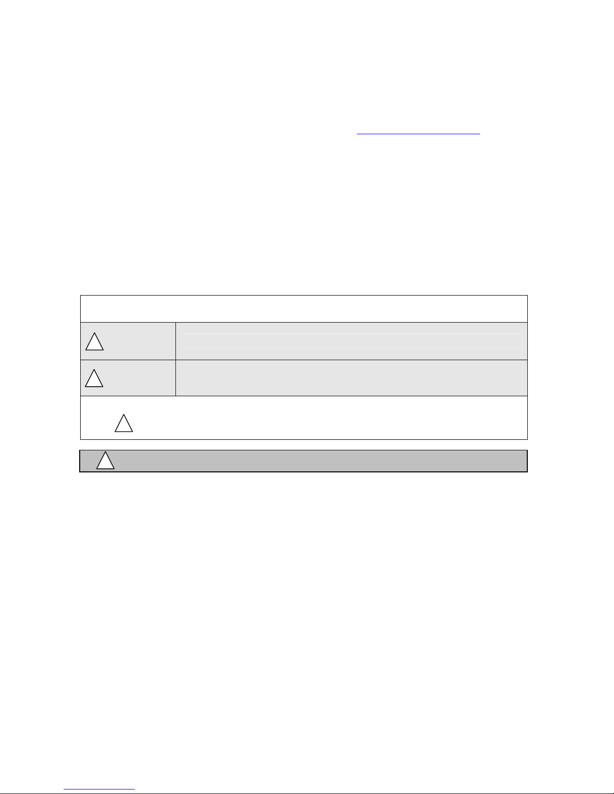
4. Product package
4.1 Accessory
- Please check accessories as follows after opening box.
If accessories have any damages or they are not in the box,
please contact sales office.
Mounting Bracket
Manual
Chart paper
2EA
[Figure 4-1 Product package]
4.2 Ordering codes
KRN50 - 2 0 0 4 - 4 0
50Ω B class high-
accuracy
resistor(0.1%)
2EA
① ② ③ ④ ⑤ ⑥ ⑦
① Item/Series KRN50 KONICS Thermal Line Recorder(50mm)
channel
③ Ch1 Control output 0 None
④ Ch2 Control output 0 None
⑤ Alarm output
⑥ Option output
⑦ Power supply 0 100 ~ 240VAC, 50 ~ 60Hz
1 1 Channel ② The number of
2 2 Channel
0 None
2 Alarm output 2 EA ※1
※2
4 Alarm output 4 EA
0 None
4 Communication output (RS485)
6

100 ~ 240VAC, 50 ~ 60Hz
1 Channel
None
Alarm 0 EA KRN50-1000-00 KRN50-1000-40
Alarm 2 EA KRN50-1002-00 KRN50-1002-40
Communication
output (RS485)
Alarm 0 EA KRN50-2000-00 KRN50-2000-40
2 Channel
Alarm 2 EA KRN50-2002-00 KRN50-2002-40
Alarm 4 EA KRN50-2004-00 KRN50-2004-40
※1. In case of selection of 2 channel model, it is able to use 2 alarm
outputs by means of alarm output of CH1. Therefore it is not possible
that Ch1 has 1 alarm and Ch2 has 1 alarm separately.
※2. It is able to be selected in case of only 2 channel model.
5. Explanation for function and name of parts
5.1 Function
KRN50 recorder is able to measure Thermocouple, RTD, DC-voltage
(1V,10V,50mV,200mV) DC-current(0~20mA,4~20mA) signal by total
2 input channels. Measured signal records by digital and graph type through
setting a variety of recording speed.
Alarm
: Input 1 channel can have 2 alarm outputs. Alarm output is operating by
a kinds of modes (None, Latch, Stand-by, Latch+Stand-by) through
High limit, Low limit, Sensor break, Paper end function.
Alarm outputs by relay contact.
Recording
: Measured signal records by digital and graph type. Recording speed is
able to set by 5sec~99min 59sec in case of digital mode (Numerical record)
and by 10~960mm/h in case of graph mode. It has memo function recording
data at the necessary time and is able to output time, date, alarm
information, error message, parameter list and so on.
Display
: Measured value is indicated by number on LCD display and time, alarm,
error information, etc. are displayed.
Communication Function
: It is able to use RS-485 communication and communication protocol
uses ModBus RTU and communicates with the upper devices, PC or PLC.
Data back-up
: It is similar to data logger function. In case of graph mode and 10mm/h
recording speed, approx. 10-day-data is able to be saved in EEPROM
memory. Therefore user can output the saved data from the memory by
graph or digital type.
Also even though chart paper is exhausted all, data is able to be saved
to the saving space according to recording speed.
Other function
: Feeding function and recording start/stop function are able to be used by
front key or communication at the status of recording stop. Also recording
reservation function is able to start or stop recording at the suitable time
period user wants.
7
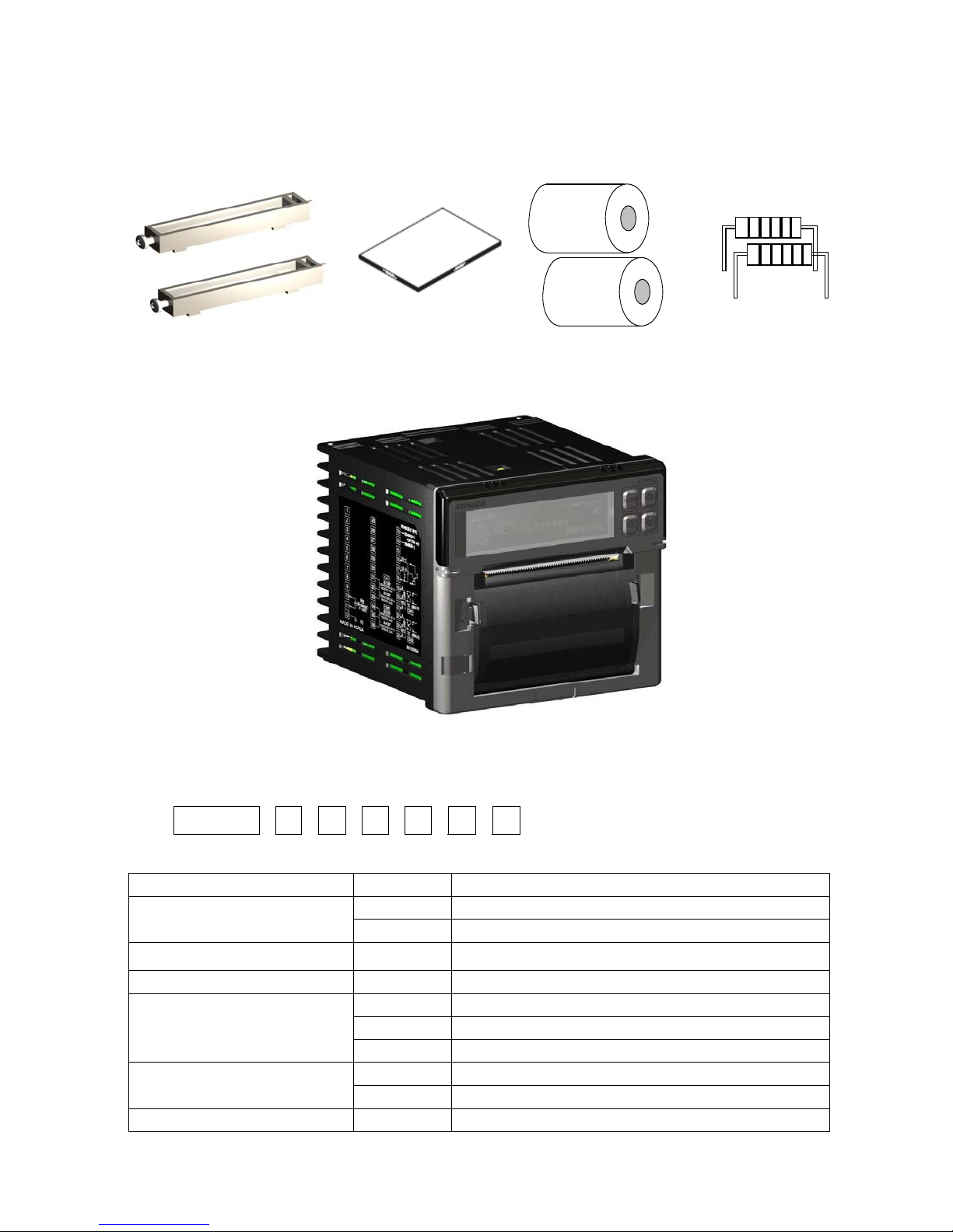
5.2 Part name
Connections
Terminal
block
Phone Jack
Cover
[ Figure 5-1 Each part name ]
Chart Paper
Cutter
ChartPaper
Roller
8
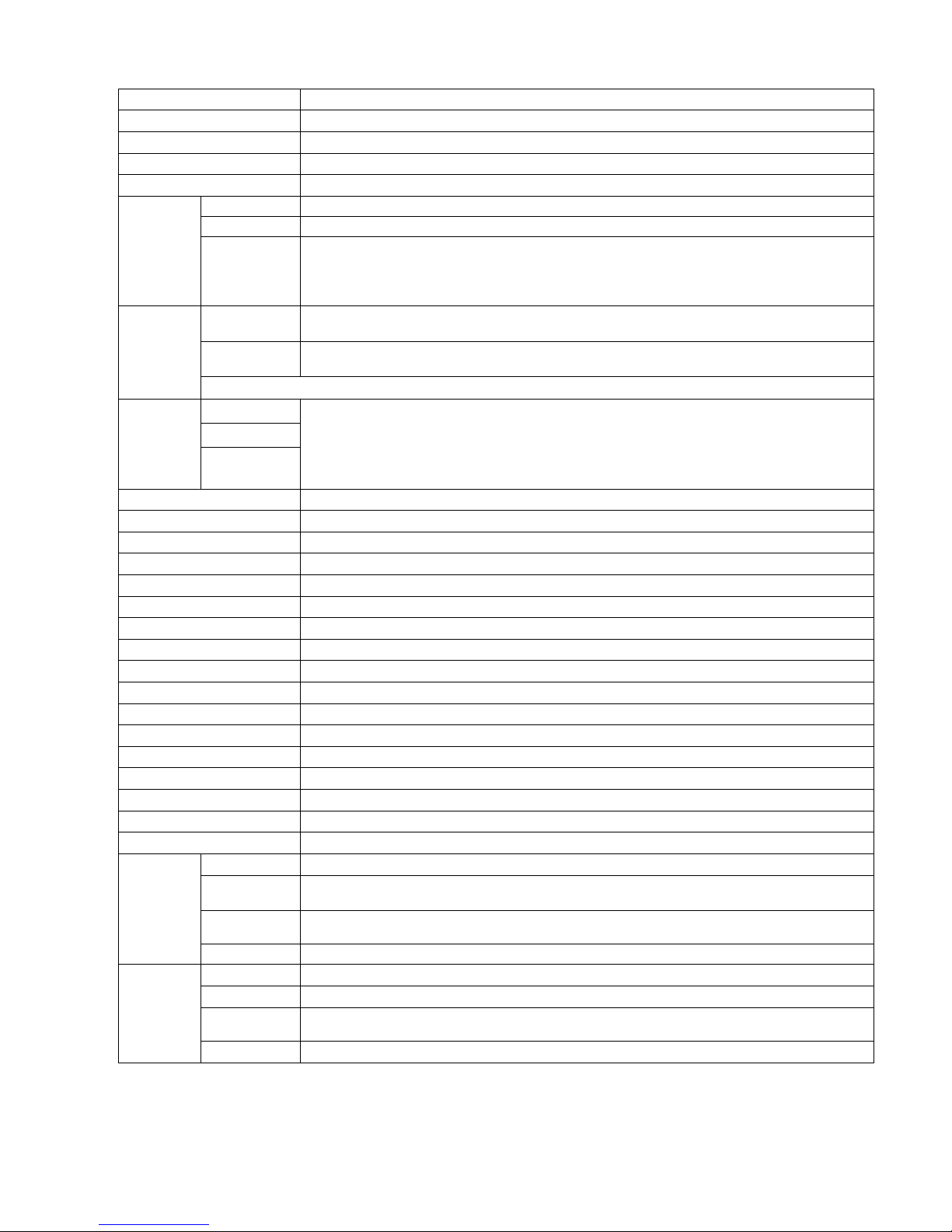
5.3 Specifications
Series KRN50 series
Model KRN50-□00□-□0 (※ Refer to page no.6)
Power supply 100 ~ 240VAC 50~60Hz
Power consumption Max. 34VA (240VAC 60Hz)
Display LCD Dot Matrix Display (Resolution 128 X 32 Dot)
RTD
T/C K, J, E, T, B, R, S, N, C, G, L, U, PLII
Input
Analog
Contact
Event
input
input
Non-contact
input
RTD
Indicating
T/C
accuracy
Analog
Recording accuracy F.S.±0.5%
Alarm output Relay contacting point capacity 250VAC/30VDC 3A 1a(Resistive load)
Alarm hysteresis Set ON/OFF interval : within 1 ~ 999 Digit
Communication output
Setting method Set by key
Sampling cycle 500ms/channel X 2 channels = 1000ms
Internal voltage
Internal vibration
Life of relay Electrical Contact Rating 10 x 104 operations minimum
Isolation resistance Min. 100MΩ (500VDC Mega STD.)
Internal noise ±2kV the square wave noise(Pulse width : 1us) by the noise simulator
Ambient temperature 0 ~ 50℃ (at non-freezing status)
Storage temperature - 20 ~ 60℃ (at non-freezing status)
Ambient humidity 35 ~ 85% R.H.
Terminal bolt M3 screw Type Terminal
Weight
Dimensions W96 x H96 x L100 mm
Method Direct Thermal Line Print
Limit of
Print
resolution
Total dot
number
Life 50km
Paper Thermal Direct Receipt Paper(57mm x 16m)
Speed 10, 30, 60, 120, 240, 480, 960mm/hour
Recording
Supplying
paper type
※
1. C(TT): Same temp.sensor as previous W5(TT) ※
※
3. Exceptional section of measuring accuracy for each sensor
Language Korean, English
J: -200≤T≤-100 ±2.7℃, R,S,C,G: 0≤T≤100 ±5.2℃
B: No accuracy regulation under 400
JPT100Ω, DPT100Ω, DPT50Ω, CU100Ω, CU50Ω, Supplying current 420uA
ᆞVoltage:-50.0~50.0mV, -199.0~200.0mV, -1.000~1.000V, -1.00~10.00V
ᆞ
Current:0.00~20.00mA, 4.00~20.00mA
※ B class (0.1%) 50Ω high-accuracy resistor outside must be
connected in case of current input
Input ON: Max. 1kΩ OFF: Min. 100kΩ
Input ON: Remaining voltage Max. 1V OFF: Leakage current Max. 0.05mA
Short circuit : Approx. 0.3mA
±0.2% F.S. ±1 Digit(25±5℃), ±0.3% F.S. ±1 Digit(0~20℃,30~50℃),
But, under -100℃ in T/C, ±0.4% F.S. ±1 Digit
(In case of TC-K2, it has same accuracy with –200~1350℃ range
at the basis of TC-K1)
(※ Exception section of measuring accuracy for each sensor is as follows)
RS485 communication output (MODBUS RTU protocol type)
2300VAC 50/60Hz for a minute (Rechargeable terminal of another polarity)
0.75mm amplitude at frequency of 10~55Hz in each of X, Y, Z directions for 1 hour
Approx. 700g(Body 470g (Including chart paper), Metal parts for installation)
8dot/mm
384dot/Line
Clamshell Type
2. G(TT): Same temp.sensor as previous W(TT)
℃ U,T: -200≤T≤-100 ±3.5℃ -100≤T≤400 ±2.5℃
9
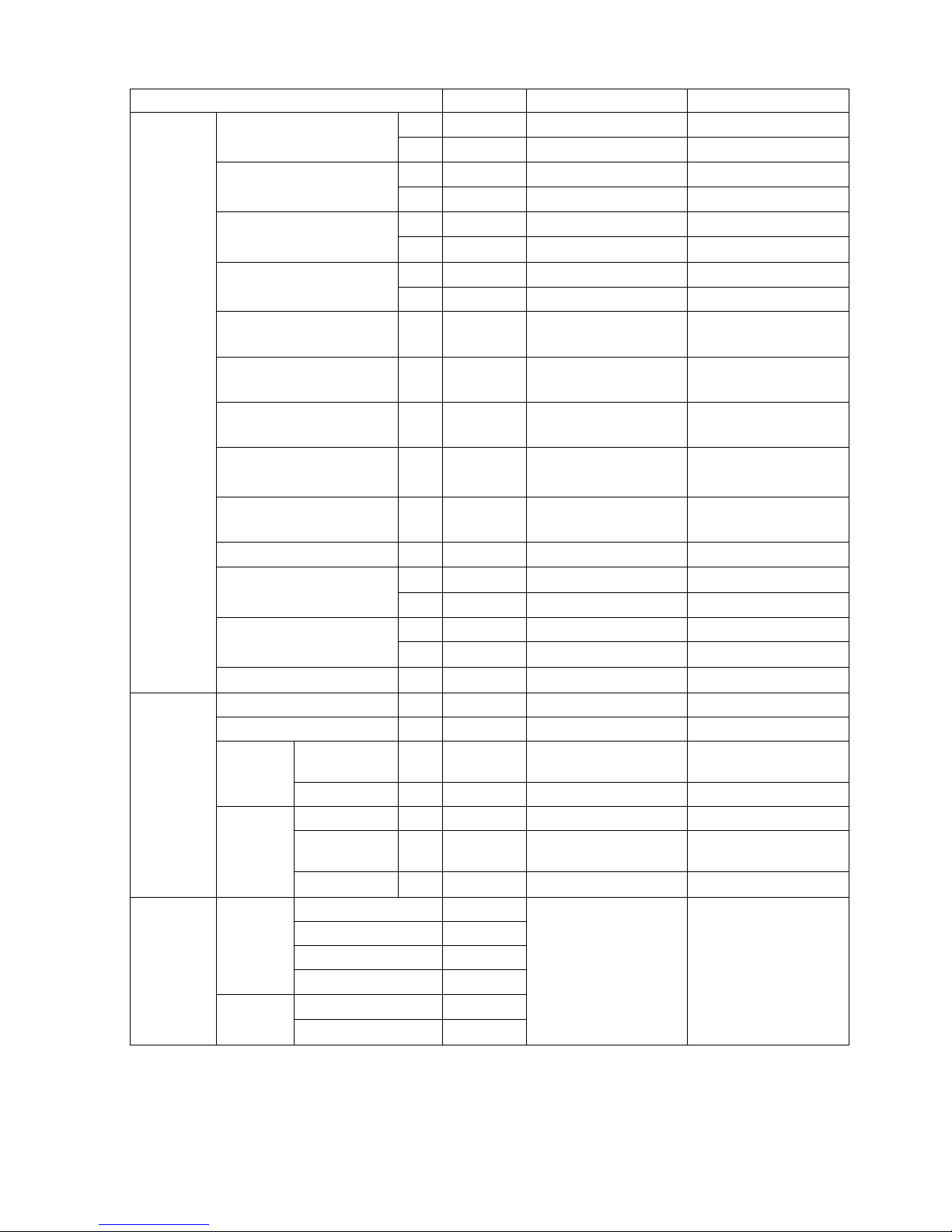
5.4 Input specifications and temp. range for sensor type
Input type
K(CA)
Chromel(+)
Alunel(-)
0.1 TC-K2 -199.9 ~ 999.9 -199.9 ~ 999.9
J(IC)
Iron(+)
Constantan(-)
0.1 TC-J2 -199.9 ~ 800.0 -199.9 ~ 999.9
E(CR)
Chromel(+)
Constantan(-)
0.1 TC-E2 -199.9 ~ 800.0 -199.9 ~ 999.9
T(CC)
Copper(+)
Constantan(-)
0.1 TC-T2 -199.9 ~ 400.0 -199.9 ~ 752.0
B(PR)
Platinum(30% Rhodium)(+)
Platinum(15% Rhodium)(-)
R(PR)
Thermo
Couple
Platinum(13% Rhodium)(+)
Platinum(-)
S(PR)
Platinum(10% Rhodium)(+)
Platinum(-)
N(NN)
Ni-Cr-Si(+)
Ni-Si-Mg(-)
C(TT) ※1
Tungsten(5% Rhodium)(+)
Tungsten(26% Rhodium)(-)
G(TT) ※2 1 TC-G 0 ~ 2300 32 ~ 4172
L(IC)
Iron(+)
Constantan(-)
0.1 TC-L2 -199.9 ~ 900.0 -199.9 ~ 999.9
U(CC)
Copper(+)
Constantan(-)
0.1 TC-U2 -199.9 ~ 400.0 -199.9 ~ 752.0
Platinel II 1 TC-P 0 ~ 1390 32 ~ 2534
CU 50Ω 0.1 CU50 -199.9 ~ 200.0 -199.9 ~ 392.0
CU 100Ω 0.1 CU100 -199.9 ~ 200.0 -199.9 ~ 392.0
JPt 100Ω
JIS
RTD
(3916)
JPt 100Ω 0.1 JPT2 -199.9 ~ 600.0 -199.9 ~ 999.9
DPt 50Ω 0.1 DPT50 -199.9 ~ 600.0 -199.9 ~ 999.9
DIN
DPt 100Ω
(385)
DPt 100Ω 0.1 DPT2 -199.9 ~ 600.0 -199.9 ~ 999.9
-50.0~50.0mV 50mV
Voltage
-199.9~200.0mV
-1.000~1.000V 1V
Analog
Current
-1.00~10.00V 10V
0~20mA 0-20
4~20mA 4-20
※1. C(TT) : Same temp.sensor as previous W5(TT)
※2. G(TT) : Same temp.sensor as previous W(TT)
Display
Temp. range (℃) Temp. range (℉)
1 TC-K1 -200 ~ 1350 -328 ~ 2462
1 TC-J1 -200 ~ 800 -328 ~ 1472
1 TC-E1 -200 ~ 800 -328 ~ 1472
1 TC-T1 -200 ~ 400 -328 ~ 752
1 TC- B 100 ~ 1800 212 ~ 3272
1 TC-R 0 ~ 1750 32 ~ 3182
1 TC-S 0 ~ 1750 32 ~ 3182
1 TC-N -200 ~ 1300 -328 ~ 2372
1 TC-C 0 ~ 2300 32 ~ 4172
1 TC-L1 -200 ~ 900 -328 ~ 1652
1 TC-U1 -200 ~ 400 -328 ~ 752
1 JPT1 -200 ~ 600 -328 ~ 1112
1 DPT1 -200 ~ 600 -328 ~ 1112
200mV
-1999 ~ 9999
(
Display range is
different according
to the decimal
point
-1999 ~ 9999
(
Display range is
different according
to the decimal
.)
point
.)
10
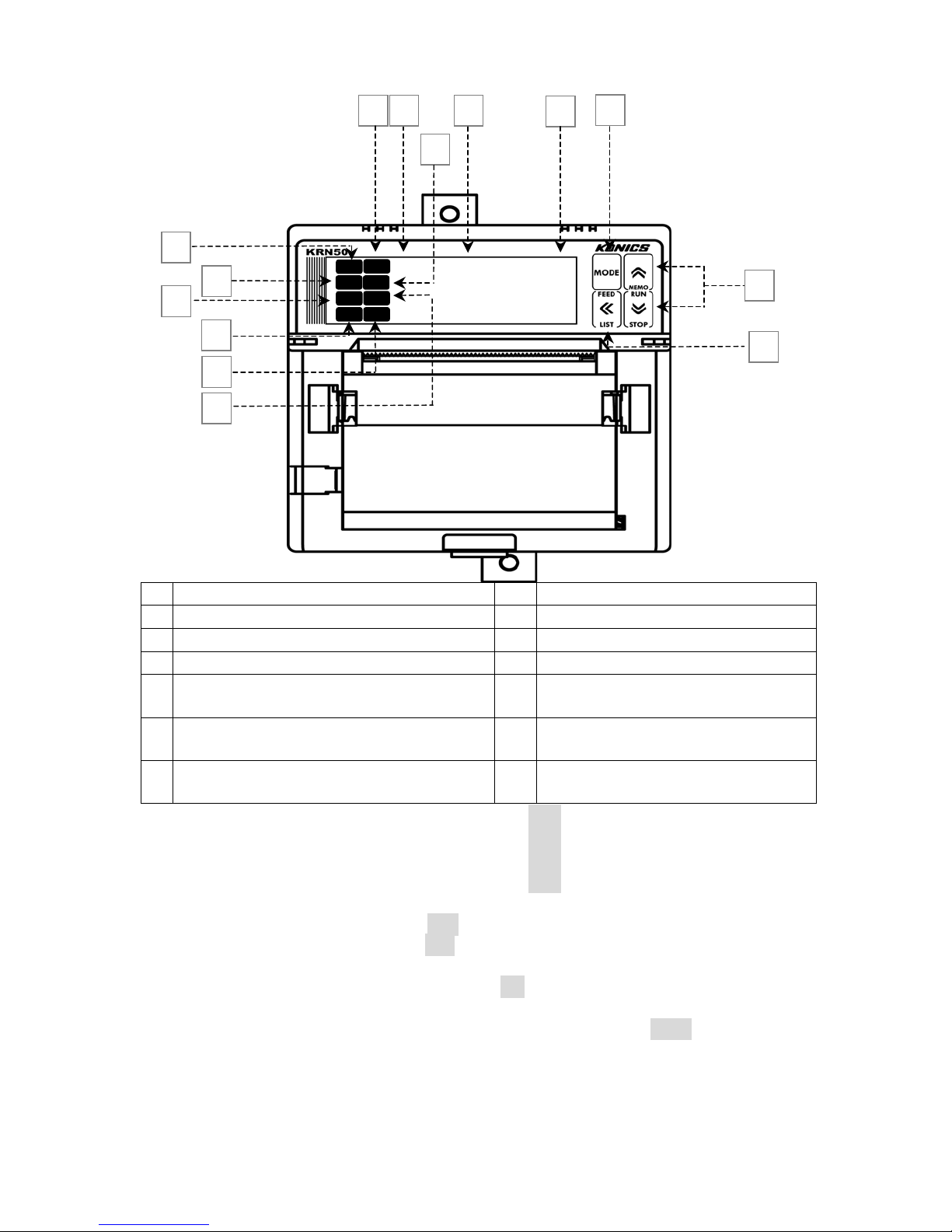
5.5 Front display and setting key
/
2
5 11
8
1
>>>
3
2
4
7
6
AL1
AL2
AL1
AL2
D I
R E
P.E D
CH1
CH2
14
9
9.9.9. 9.
10
℃
9.9.9.9.
Kgf
cm
12
13
CH 1-AL1 alarm output indicating lamp
1
2
CH 1-AL2 alarm output indicating lamp
3
CH 2-AL1 alarm output indicating lamp
4
CH 2-AL2 alarm output indicating lamp
Recording start(>>>)/Recording
5
stop(■) indicating lamp
Recording reservation(RE)
6
indicating lamp
Recording paper end(P.ED)
7
indicating lamp
1)
CH 1-AL1 alarm output indicating lamp : When AL1 of input channel 1 is on, indicated.
2)
CH 1-AL2 alarm output indicating lamp : When AL2 of input channel 1 is on, indicated.
3)
CH 2-AL1 alarm output indicating lamp : When AL1 of input channel 2 is on, indicated.
4)
CH 2-AL2 alarm output indicating lamp : When AL2 of input channel 2 is on, indicated.
8 Channel(CH) display
9 Processing value(PV) display
10 Unit display
11 Mode key
Up/Down control and special
12
function key
13 Shift and special function key
14 Digital input display
5) Recording start(>>>)/Recording stop(■) indicating lamp
: When recording start (RUN), >>> is indicated,
when recording stop (STOP), ■ is indicated.
6) Recording reservation(RE) indicating lamp
: When recording reservation operates, RE is indicated.
7) Recording paper status(P.ED) indicating lamp
: During recording (RUN), if chart paper is exhausted all, P.ED is indicated.
8) Channel(CH) display : Input channel number of processing value on
PV display is indicated.
9) Processing value(PV) display
: When RUN mode, processing value for relevant channel is indicated.
When setting mode, parameter and mode setting value are indicated.
11
10) Unit display : Unit of relevant channel is indicated.
11) Mode key : Use it when entering into setting mode and changing SV of mode.
12) Up/Down control key
: Use it when moving parameter and increasing/decreasing digit value.
- ∧ Key : Digital memo operating key
- ∨ Key : Recording Run/Stop operating key
13) Shift key
: Use it when moving parameter to upper group or moving digit on setting mode.
- ≪ key : When STOP mode, it is used for paper feeding.
When RUN mode, it is used for printing parameter setting information.
14) Digital input display : The setting digital input function is indicated.
6. Mounting and wiring
6.1 Mounting
6.1.1 Mounting location
This recorder must be mounted at the satisfied location as following condition.
- Instrument Panel
This recorder is panel mounting type.
- Airy location
This recorder must be mounted in order to prevent from overheating
(Using temp. range : 0~50℃) and follows the panel cut-out if mounting
some recorders together.
- Minimum vibrating location
This recorder must be mounted at the minimum vibrating location
where mechanism is not be influenced (Device related with print).
NOTE
●
If mounting at the location having sharply fluctuating temp. and measuring temp.
by thermocouple sensor, measured data may cause an accidental error.
Also if preheating to ambient temp. for over 30 min. before using,
measured data will be precise.
●
Chart paper may discolor if using the location having sharply fluctuating
temp. and humidity.
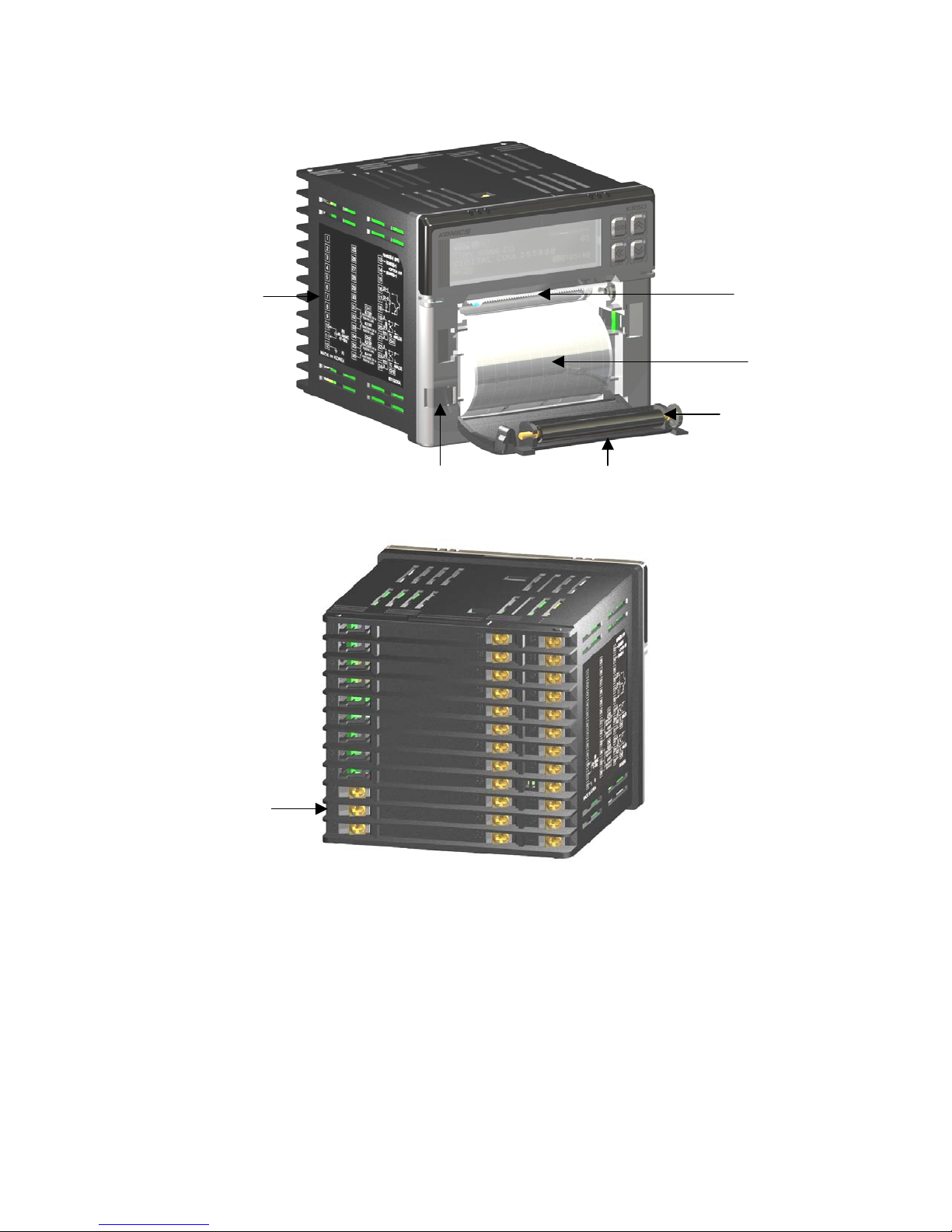
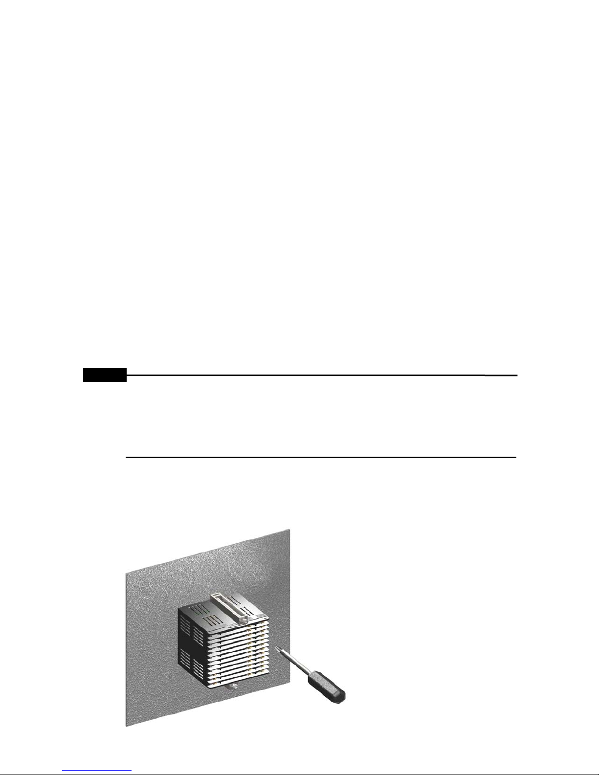
6.1.2 Panel mounting
This recorder must be mounted to the panel of max. 4mm thickness.
1. Insert recorder to the panel.
2.
Insert 2 fixed brackets to each bracket slots and fix them by approx. 0.3 N.m.
[Figure 6-1 Panel mounting]
12
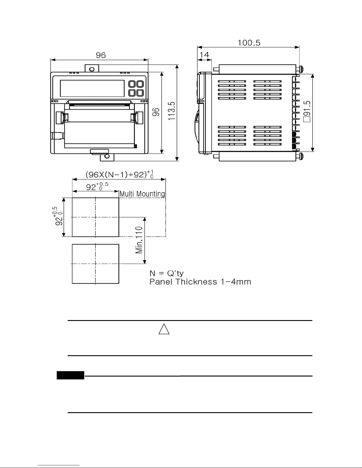
6.1.3 Dimensions and panel cut-out
!
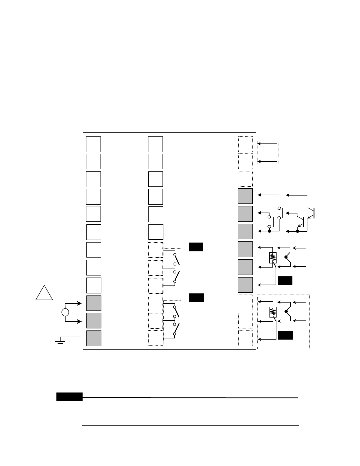
6.2 Wiring
ᆞPlease connect wiring after power off in order to prevent from an electric shock.
ᆞ
Please check input specifications in order to prevent from any damages.
FNOTE
ᆞ
If using only 1 channel in case of 2 channel model, please short-circuit the
ᆞ
If cable connected with recorder has strong power, it may cause damage to
[Figure 6-2 Dimensions and panel cut-out]
Warning
input channel (+,- input) not used in order to prevent from noise influence.
recorder or terminal block.
13
- Please be care of wiring as follows in order to prevent from noise.
1. Input must be installed as far as possible from power line.
2. Terminal wiring must be divided from high-voltage and high-current
power line in order to prevent from electricity failure and self-induction
noise. Also please avoid parallel wiring or same wiring with power line.
It may be effective if dividing by means of pipe or duct or using shield
cable or twist-pair cable.
3. Same compensating wire must be used for precise measurement when
thermocouple lead wire need to extend.
If not, it may cause an accidental error.
When RTD lead wire need to extend, please use it with small resistance
value and be equal for resistive value to 3 lead wires.
Communication
Output
RS485
1
2
25
26
13
14
RS485(A+)
RS485(B-)
!
SOURCE
100-240VAC
50~60Hz
FG
~
NOTE
3
4
5
6
7
8
9
10
11
12
27
28
29
30
31
32
33
34
35
36
Ch1
AL1 OUT
250VAC/30VDC 3A 1a
RESISTIVE LOAD
AL2 OUT
250VAC/30VDC 3A 1a
RESISTIVE LOAD
Ch2
AL1 OUT
250VAC/30VDC 3A 1a
RESISTIVE LOAD
AL2 OUT
250VAC/30VDC 3A 1a
RESISTIVE LOAD
15
16
17
18
19
20
21
22
23
24
Digital Input
Contact
Non-contact
Input input
DI-1
DI-2
A
B
RTD
b
A
B
RTD
b
Sensor
[Figure 6-3 Connections]
※ Shaded terminals are in case of basic/standard model.
(For power supply, CH1 input, DI input)
※ Dotted-line terminals are in case of option model.
(For input, alarm output, communication output)
1. If using 2-wire RTD, please be short-circuit B, b terminals.
2. In case of current input, external 50Ω B class(0.1%)
high-accuracy resistor must be connected.
+
-
TC
Ch1
+
-
TC
Ch2
+
-
ANALOG
+
-
ANALOG
14

7. General operation and parameter setting menu
/
7.1 Operation mode
Recorder has 3 kinds of operation modes.
- Common operation mode
This mode operates when normal operation.
This mode operates when power on.
- Setting mode
This mode is to set the parameters as like input range, alarm, recording
speed, etc. This mode is able to set even if operation does not stop on
common operation mode.
- Backup data recording mode
This mode is to record the saved data by means of data logger function.
It is also unnecessary for operation stop.
Operation Mode
AL1
>>>
AL2
AL1
AL2
CH2
P.ED
7.2 Operation procedure
It is the introduction when this recorder operates initially.
- Ready to record
Put chart paper in paper holder after cutting the glued part (When delivery,
chart paper is installed in recorder). If necessary, change time and date
(When delivery, they are set).
- Set input and relevant parameter
Set relevant parameter according to input sensor.
ᆞSet input type and alarm
ᆞSet recording speed
- Record and display measuring value
ᆞIf necessary, press down key for recording Run / Stop.
Also mode is able to be changed by measuring value display mode
relevant key.
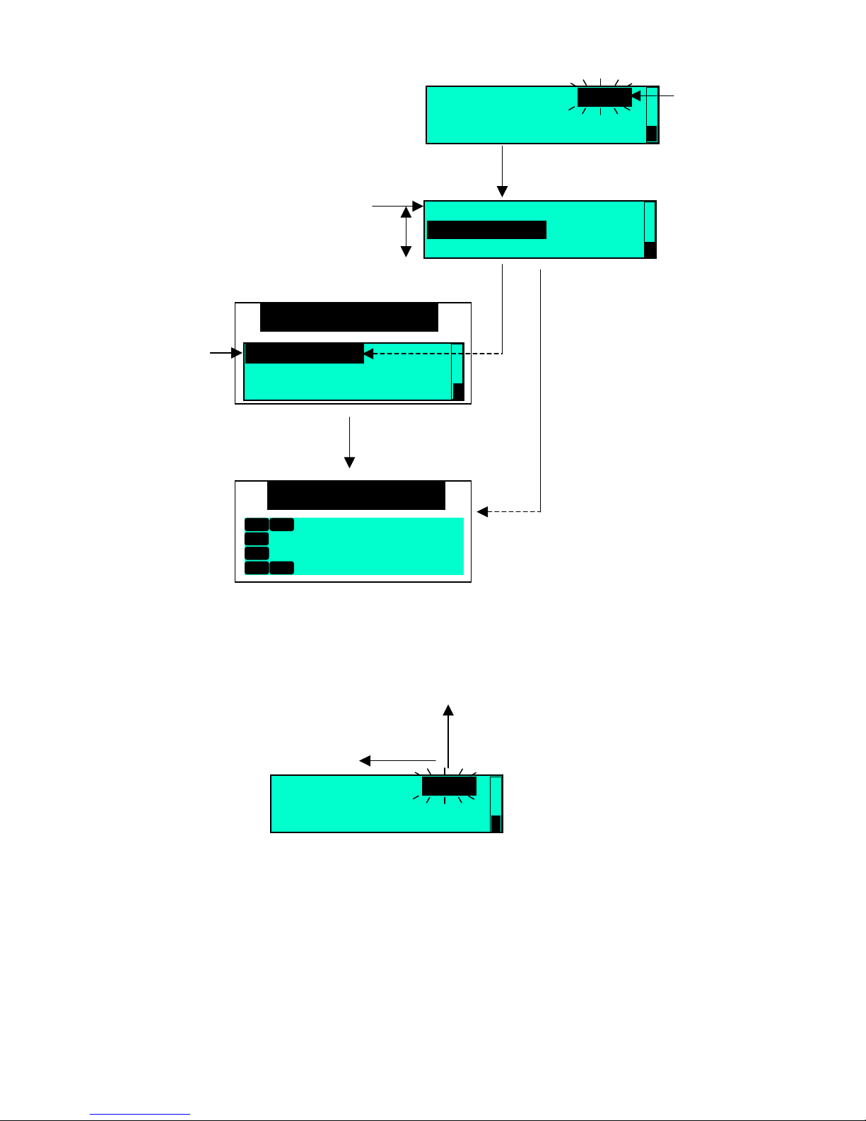
7.3 Setting key
- Enter into the setting mode
1. If press mode key for 3 sec, it enters into setting mode. After then the
upper setting menu refer to figure 7-2 is indicating and the cursor is
placed on relevant the upper setting menu. Scroll bar at the right side
shows the rest of the setting menu.
2. If moving from the upper setting menu to the next step menu,
please use ∨,∧ key.
3. If press mode key, it is able to move from the current menu to the lower
setting menu. (For moving from the lower setting menu to the upper
setting menu, please use ≪ key.)
9
9
.
. 9. 9.
CH1
℃
9. 9. 9.
9
.
InputSetup
Alarm Setup
Kgf
cm2
Reservation Setup
[Figure 7-1 Display for each mode]
Setup Mode
15
Back up Data
Recording Mode
Recording...
Continuous Stop

4. If moving from the lower setting menu to the next step menu,
gory
y
/
2
please use ∨,∧ key.
5. If entering into the setting category at the lower setting menu,
the cursor is flickering on the setting category. Then, user is able to
change the setting category by means of ≪ or ∨,∧ key.
Upper setting
menu
Lower setting
- Get out of the setting mode
1. If press mode key after changing the setting category,
2. The lower setting menu is able to be selected by ∨,∧ key and
if press ≪ key, moving to the upper setting menu.
3. If press mode key for 3 sec when the cursor is placed at the lower
setting menu, it is able to move to the setting mode from general
operation mode and operate according to setting value.
Operation Mode
AL1
>>>
AL2
AL1
AL2
P.ED
CH1
CH2
9.9.9.
9.9. 9.9.
9.
℃
Kgf
cm
Mode key for 3 sec
Setup Mode
Input Type Setup
Scroll Bar
Alarm Setup
Reservation Setup
∨∧ ke
Mode key
menu
∨∧ key
CH1 AL1 Type: PV.Hi
CH1 AL1 Opt : None
CH1 AL1 Low : -200
`Mode key
CH1 AL1 Type: PV.Hi
CH1 AL1 Opt : None
CH1 AL1 Low : -200
Setting
cate
∨∧ key or ≪ key
[Figure 7-2 Setting mode entrance display]
setting value is saved and moving to the next lower setting menu.
16
CH1 AL1 Type: PV.Hi
/
2
CH1 AL1 Opt : None
CH1 AL1 Low : -200
`Mode key
Setting
category
Upper setting
menu
- Change the setting category
If press mode key after changing the setting category by ∨,∧ key,
it is saved and moved to the setting menu.
Lower setting
menu
∨∧ key
Setup Mode
Alarm Setup
Reservation Setup
`Mode key for 3 sec
Operation Mode
AL1
>>>
P.ED
CH1
CH2
9
AL2
AL1
AL2
CH1 AL1 Type: PV.Hi
CH1 AL1 Opt : None
CH1 AL1 Low : -200
9.9. 9.9.
.
9
.9.9.
Mode key
CH1 AL1 Type: PV.Hi
CH1 AL1 Opt : None
CH1 AL2 Type: off
≪ key
℃
Kgf
cm
∨∧ key or ≪ key
17

- Insert setting value
After moving the cursor to the position user wants to the left by ≪ key,
it is able to change the value by ∨,∧ key. Especially the fourth position of
number is able to change to either number or sign.
CH1 AL1 Low:
≪ key
If press mode key at the status of wrong value and save it when
changing setting value, it indicates Error code as above.
(Error code is referred to page no.54)
`
0
-
-1
∨∧ key
9 200
`
8
∨∧ key
7
6
CH1 Lo Graph : -200
CH1 Hi Graph : 1350
CH1 In Bias : 0000
Hi < Lo !!
CH1 AL1 Low: 92 00
≪ key
5
4
3
1
0
9
∨∧ key
∨∧ key
18
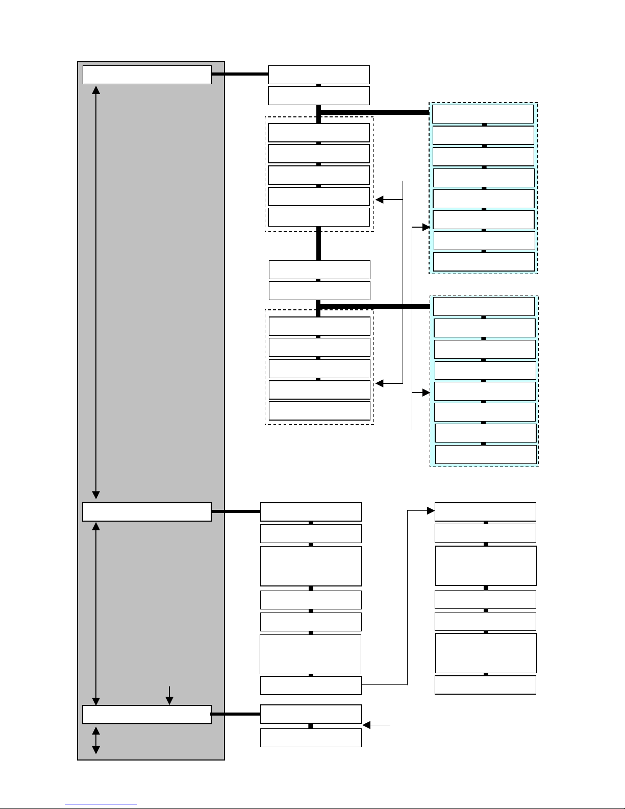
7.4 Parameter setting group
p
Input Type Setup
※ Parameter setting model
All models
∨∧ key
Alarm Setup
※ Parameter setting model
KRN50-1002-00
KRN50-1002-40
KRN50-2002-00
KRN50-2002-40
KRN50-2004-00
KRN50-2004-40
∨∧ key
※ Parameter setting model
All models
Reservation Setup
∨∧ key
MODE
key
CH1 In Type
CH1 Temp Unit
CH1 Lo Graph
CH1 Hi Graph
CH1 In Bias
CH1 Tag Name
CH1 Record
In case of 2 channel
input model
CH2 Record
CH2 In Type
CH2 Temp Unit
CH2 Lo Graph
CH2 Hi Graph
CH2 In Bias
CH2 Tag Name
MODE
key
CH1 AL1 Type
CH1 AL1 Opt
CH1 AL1 Low
CH1 AL1 High
CH1 AL2 Type
CH1 AL2 Opt
CH1 AL2 Low
CH1 AL2 High
CH1 Alarm Hys
MODE
key
Start Time
Stop Time
or
or
TC or RTD
∨∧ key
∨∧ key
CH1 Lo Range
CH1 Hi Range
In case of
input type
CH1 Lo Scale
CH1 Hi Scale
CH1 Sc point
CH1 Dp Unit
CH1 In Bias
CH1 Tag Name
CH2 Lo Range
CH2 Hi Range
CH2 Lo Scale
CH2 Hi Scale
CH2 Sc point
CH2 Dp Unit
In case of
analog
input type
CH2 In Bias
CH2 Tag Name
In case of 2 channel
alarm output model
CH2 AL1 Type
CH2 AL1 Opt
CH2 AL1 Low
CH2 AL1 High
CH2 AL2 Type
CH2 AL2 Opt
CH2 AL2 Low
CH2 AL2 High
CH2 Alarm Hys
If recording reservation
function
arameter is “ON”
or
or
19
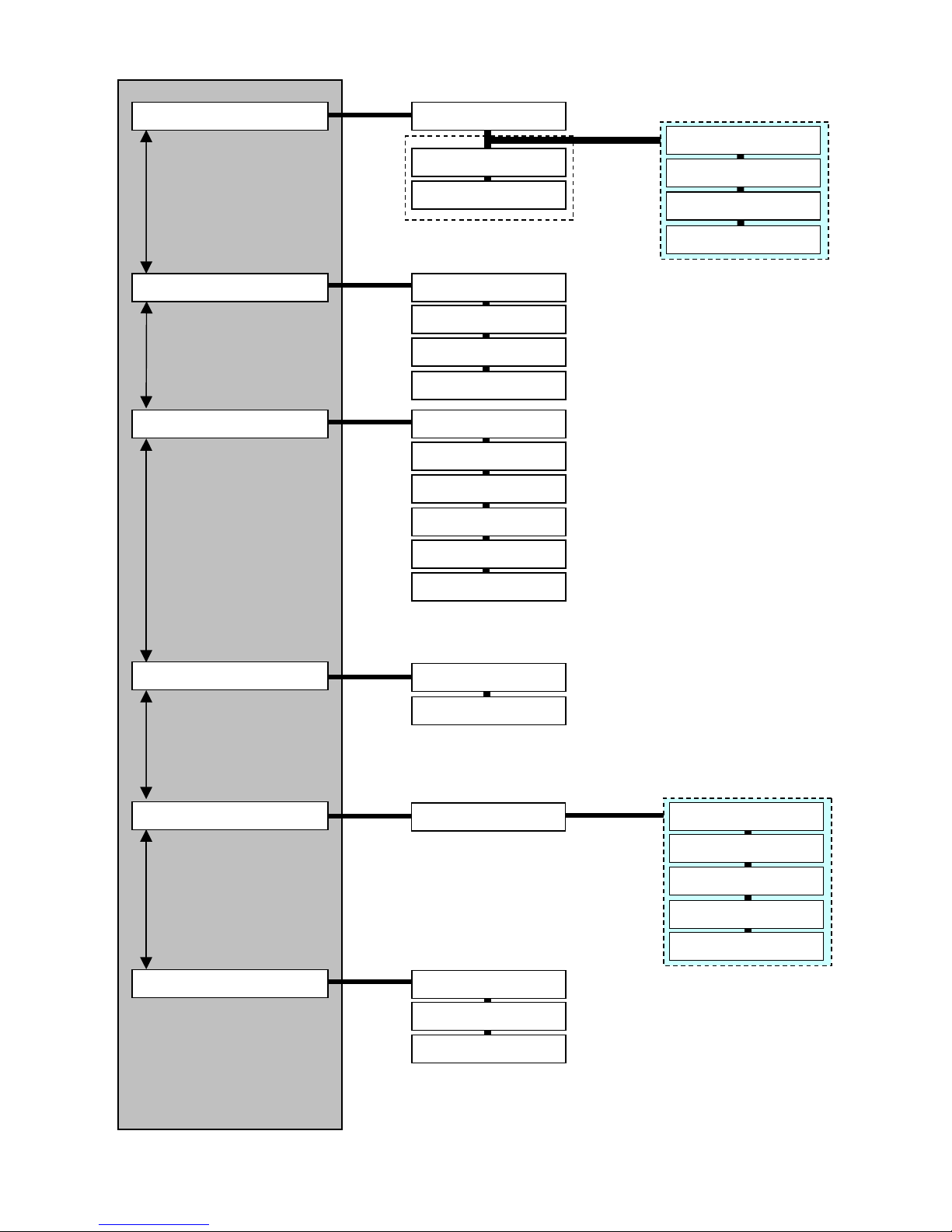
Record Setup
※ Parameter setting model
All models
∨∧ key
Option Setup
※ Parameter setting model
All models
∨∧ key
RS485 Setup
※ Parameter setting model
KRN50-1000-40
KRN50-1002-40
KRN50-2000-40
KRN50-2002-40
KRN50-2004-40
∨∧ key
Date/Time Setup
※ Parameter setting model
All models
∨∧ key
Record Backup_data
※ Parameter setting model
All models
∨∧ key
Environment Setup
※ Parameter setting model
All models
MODE
Key
MODE
Key
MODE
Key
MODE
Key
MODE
Key
MODE
Key
Rec Mode
Rec Period
Font
In case of setting
Digital Mode
Digital Input1
Digital Input2
PWR On State
Run On State
Address
Baud Rate
Parity Bit
Stop Bit
Resp Time
Com Write
Date
Time
Rec BackUp
Display Mode
Backlight
Setting Lock
Rec Speed
Memo Period
Font
Alarm Speed
In case of setting
Graph Mode
If record backup data
parameter is “YES”
Start
Stop
Graph
Digital
Cancle
In case of 2 channel
input model
20
 Loading...