

KONICS KRN1000 SERIES User Manual

USER MANUAL
© Copyright Reserved KONICS Co., Ltd. i

ii © Copyright Reserved KONICS Co., Ltd.

Preface
Preface
Thank you for purchasing KONICS product.
Please familiarize yourself with the information contained in the Safety Precautions section
before using this product.
This user manual contains information about the product and its proper use, and should be kept
in a place where it will be easy to access.
© Copyright Reserved KONICS Co., Ltd. iii

User Manual Guide
User Manual Guide
Please familiarize yourself with the information in this manual before using the product.
This manual provides detailed information on the product's features. It does not offer any
guarantee concerning matters beyond the scope of this manual.
This manual may not be edited or reproduced in either part or whole without permission.
A user manual is not provided as part of the product package.
Visit our web site (www.konics.com) to download a copy.
The manual's content may vary depending on changes to the product's software and other
unforeseen developments within KONICS, and is subject to change without prior notice.
Update notice is provided through out homepage.
We contrived to describe this manual more easily and correctly. However, if there are any
corrections or questions, please notify us these on our homepage.
iv © Copyright Reserved KONICS Co., Ltd.
User Manual Symbols
Symbol
Description
User Manual Symbols
Supplementary information for a particular feature.
Failure to follow instructions can result in serious injury or death.
Failure to follow instructions can lead to a minor injury or product damage.
An example of the concerned feature's use.
※1
Annotation mark.
© Copyright Reserved KONICS Co., Ltd. v
Safety Precautions
Safety Precautions
Following these safety precautions will ensure the safe and proper use of the product and
help prevent accidents, as well as minimizing possible hazards.
Safety precautions are categorized as Warnings and Cautions, as defined below:
Warning
Caution
Failure to follow the instructions may lead to a serious injury
or accident.
Failure to follow the instructions may lead to a minor injury
or accident.
Fail-safe device must be installed when using the unit with machinery that may cause
serious injury or substantial economic loss. (e.g. nuclear power control, medical equipment,
ships, vehicles, railways, aircraft, combustion apparatus, safety equipment, crime/disaster
prevention devices, etc.)
Failure to follow this instruction may result in personal injury, fire, or economic loss.
The unit must be installed on a device panel before use.
Failure to follow this instruction may result in electric shock.
Do not connect, repair, or inspect the unit while connected to a power source.
Failure to follow this instruction may result in electric shock.
Check the terminal numbers before connecting the power source.
Failure to follow this instruction may result in fire or burning the unit.
Lithium battery is used in the unit. Do not disassemble or burn the unit.
Failure to follow this instruction may result in explosion.
Do not touch the unit and terminals after cut off the power within 30 sec.
Failure to follow this instruction may result in electric shock.
Ground PE terminal individually and ground cable should be over AWG16 (1.25 mm
Failure to follow this instruction may result in electric shock.
Do not insert any objects at the openings of the unit.
Failure to follow this instruction may result in electric shock or personal injury.
Do not disassemble or modify the unit. Please contact us if necessary.
Failure to follow this instruction may result in personal injury, fire, or economic loss.
Do not use the unit outdoors.
Failure to follow this instruction may result in shortening the life cycle of the unit, or electric
shock.
2
When connecting the power input and relay output cables, use AWG20 (0.05mm
) cables
and make sure to tighten the terminal screw bolt above 0.74N.m to 0.90N.m.
Failure to follow this instruction may result in fire due to contact failure.
Use the unit within the rated specifications.
Failure to follow this instruction may result in shortening the life cycle of the unit, or fire.
2
).
vi © Copyright Reserved KONICS Co., Ltd.

Safety Precautions
Do not use loads beyond the rated switching capacity of the relay contact.
Failure to follow this instruction may result in insulation failure, contact melt, contact failure,
relay broken, or fire.
When connecting magnet contact as relay contact output load, attach a surge absorber at
contact coil.
Failure to follow this instruction may result in product malfunction.
Do not use water or oil-based detergent when cleaning the unit. Use dry cloth to clearn the
unit.
Failure to follow this instruction may result in electric shock, or fire.
Do not use the unit where flammable or explosive gas, humidity, direct sunlight, radiant heat,
vibration, or impact may be present.
Failure to follow this instruction may result in fire or explosion.
Keep dust and wire residue from flowing into the unit.
Failure to follow this instruction may result in fire or product damage.
Check the polarity before connecting cables.
Failure to follow this instruction may result in fire or explosion.
Check the polarity of the measurement input contact before wiring the temperature sensor.
Failure to follow this instruction may result in fire or explosion.
Check the connection diagram of this manual before supplying power.
Failure to follow this instruction may result in fire.
Do not touch terminal during dielectric or insulation resistance test.
Failure to follow this instruction may result in electric shock.
Use insulation transformer and noise filter power for too much noise from the power. Attach
noise filter on the grounded panel, etc. Use short cables for noise filter output part and
power terminal of the unit.
Failure to follow this instruction may result in product damage, malfunction by surge.
If power line and input signal line are close each other, install line filter for noise protection
at power line and use shielded input signal line.
Do not control the alarm output or measure the data during firmware update. Failure to
follow this instruction may result in malfunction. Alarm output, contact input, data
measurement do not operate normally.
After completing firmware update, check the complete message and turn OFF to ON the
power.
All parameter setting values are reset after firmware update. It may not operate as same
way with before updating operation.
Use voltage output of transmitter power output only for transmitter power. Failure to follow
this instruction may result in output module damage.
Do not press the touch screen by sharp or hard objects with excessive force.
To prevent inductive noise, separate cables of the unit from high-voltage line, power line.
Do not install inductive noise or power line closely. It may cause measurement error.
Install the unit at well-ventilated place to prevent over-heat and give space over 30mm
against wall.
Install the unit vertically.
© Copyright Reserved KONICS Co., Ltd. vii

Safety Precautions
viii © Copyright Reserved KONICS Co., Ltd.

Table of Contents
Table of Contents
Preface .............................................................................................................................iii
User Manual Guide ......................................................................................................... iv
User Manual Symbols ...................................................................................................... v
Safety Precautions .......................................................................................................... vi
Table of Contents ............................................................................................................ ix
1 Product Introduction................................................................................. 11
1.1 Features ............................................................................................................. 11
1.2 Components and accessories ........................................................................... 12
1.2.1 Components ............................................................................................... 12
1.2.2 Accessories ................................................................................................ 12
1.3 Ordering information .......................................................................................... 13
1.4 Unit description .................................................................................................. 14
1.4.1 Front part .................................................................................................... 14
1.4.2 Rear part .................................................................................................... 15
2 Specifications ............................................................................................ 17
2.1 KRN1000 ........................................................................................................... 17
2.2 Input/Output ....................................................................................................... 18
2.3 Input type and range .......................................................................................... 20
3 Dimensions ................................................................................................ 21
3.1 KRN1000 ........................................................................................................... 21
3.2 Panel cut-out ...................................................................................................... 21
4 Connections .............................................................................................. 23
4.1 KRN1000 ........................................................................................................... 23
4.2 Input/Output circuit ............................................................................................. 24
5 Installations ............................................................................................... 25
5.1 Environment ....................................................................................................... 25
5.2 Installation Method ............................................................................................. 26
5.3 USB to Serial driver ........................................................................................... 27
5.3.1 Driver installation ........................................................................................ 27
5.3.2 Check the driver ......................................................................................... 28
6 Screen ........................................................................................................ 29
6.1 Initial booting screen .......................................................................................... 29
6.2 Screen description ............................................................................................. 30
6.2.1 Status display part ...................................................................................... 30
6.2.2 Measurement value display part ................................................................ 32
6.2.3 Graph ......................................................................................................... 33
6.2.4 Pop-up menu .............................................................................................. 37
6.2.5 Virtual keyboard ......................................................................................... 38
6.2.6 Color ........................................................................................................... 40
© Copyright Reserved KONICS Co., Ltd. ix

Table of Contents
7 Menu ........................................................................................................... 41
7.1 Display ............................................................................................................... 42
7.1.1 History ........................................................................................................ 42
7.1.2 File History ................................................................................................. 44
7.1.3 Group Setting ............................................................................................. 45
7.1.4 Touch Calibration ........................................................................................ 46
7.2 Status ................................................................................................................. 47
7.2.1 Alarm List.................................................................................................... 47
7.2.2 Event List .................................................................................................... 48
7.2.3 AO/DI Status ............................................................................................... 48
7.3 Input CH Info. ..................................................................................................... 49
7.3.1 Input/Display ............................................................................................... 49
7.3.2 Input Option ................................................................................................ 53
7.3.3 Alarm .......................................................................................................... 58
7.3.4 User Unit..................................................................................................... 60
7.4 Option Info. ........................................................................................................ 61
7.4.1 Alarm Output .............................................................................................. 61
7.4.2 Digital Input................................................................................................. 62
7.4.3 RS422/485 ................................................................................................. 63
7.4.4 Ethernet/USB ............................................................................................. 64
7.5 System Info. ....................................................................................................... 66
7.5.1 Date/Time ................................................................................................... 66
7.5.2 Reservation ................................................................................................ 67
7.5.3 Device......................................................................................................... 69
7.5.4 File .............................................................................................................. 70
7.5.5 Log In.......................................................................................................... 71
7.5.6 System Info. ............................................................................................... 72
7.6 Memory Info. ...................................................................................................... 73
7.6.1 Memory Management ................................................................................ 73
7.6.2 Internal Memory ......................................................................................... 74
7.7 Screen Capture .................................................................................................. 75
7.8 Log OFF/Power OFF ......................................................................................... 76
8 Integrated device management program (DAQMaster) ......................... 77
8.1 Overview ............................................................................................................ 77
8.2 Features ............................................................................................................. 78
8.3 Dedicated features for KRN1000 ...................................................................... 79
8.3.1 Record Backup ........................................................................................... 80
8.3.2 Check backup data ..................................................................................... 81
9 Troubleshooting ........................................................................................ 83
9.1 Error message ................................................................................................... 84
x © Copyright Reserved KONICS Co., Ltd.

1 Product Introduction
1 Product Introduction
1.1 Features
KRN1000 is paperless recorder with LCD method to save recording data at SD / USB memory.
It displays trend graph, bar graph, or digital figures at TFT Color LCD.
Via RS422/485, Ethernet or USB device communication, it is available to set parameters,
transfer data as data logger functions for user convienent.
It supports several communication method and various input/output functions. It also provides
easy and convient graphic user interface (GUI) applying graphic display.
5.6-inch color TFT LCD (640×480) touchscreen display with excellent readability and
intuitive control interface
Supports 27 input types (thermocouple, RTD, analog voltage and current[shunt])
4 / 8 / 12 / 16 input channel models available
Various communication methods (RS422/485, Ethernet, USB) standard
25 to 250 ms high-speed sampling, 1 to 3600 s recording cycle
200 MB internal memory and external memory support (SD/USB up to 32 GB)
Store and backup internal data to external memory (SD/USB)
9 different graph types available
Various option input/output available: digital input (contact/non-contact), alarm output,
transmitter power output
Compact, space-saving design (rear length: 69.2 mm)
© Copyright Reserved KONICS Co., Ltd. 11
1 Product Introduction
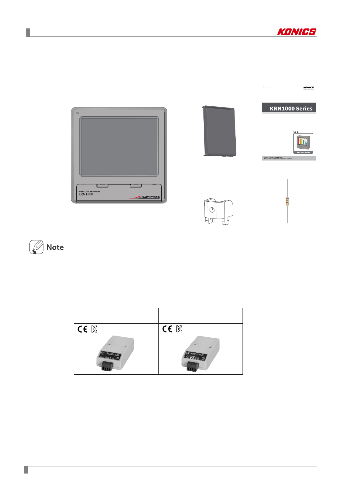
1.2 Components and accessories
1.2.1 Components
LCD Touchscreen Paperless Recorder
Rear cover User manual
KRN
Before using KRN1000, check the components.
If any component is left out or damaged, contact our company or seller.
KONICS service center: +82-32-820-2356 to 7
1.2.2 Accessories
Communication converter
SCM-38I
(RS232C to RS485 converter)
Use Autonics SCM-38I or SCM-US48I as communication converter.
SCM-38I (RS232C/RS485 converter) and SCM-US48I (USB/RS485 converter) are same
appearance.
1000
Brackets: 4
SCM-US48I
(USB to RS485 converter)
Resistance (250Ω)
12 © Copyright Reserved KONICS Co., Ltd.

1 Product Introduction
Category
Description
1.3 Ordering information
KRN1000 - 04 0 1
① ② ③ ④
⑤ ⑥
0 S
①Item
②Input channels
③Option input/output
④Communication output
KRN1000 Paperless recorder
04 4 channels
08 8 channels
12 12 channels
16 16 channels
0 None
1 Alarm relay output 8 channels
2
3
4
1 RS422/485 + Ethernet + USB Device
Alarm relay output 6 channels
+ Digital input 2 channels
Alarm relay output 6 channels
+ 24VDC power output for transmitter
Alarm relay output 4 channels
+ Digital input 2 channels
+ 24VDC power output for transmitter
⑤Power supply
⑥Case
0 100-240VAC 50/60Hz
S Standard panel installation type
© Copyright Reserved KONICS Co., Ltd. 13
1 Product Introduction
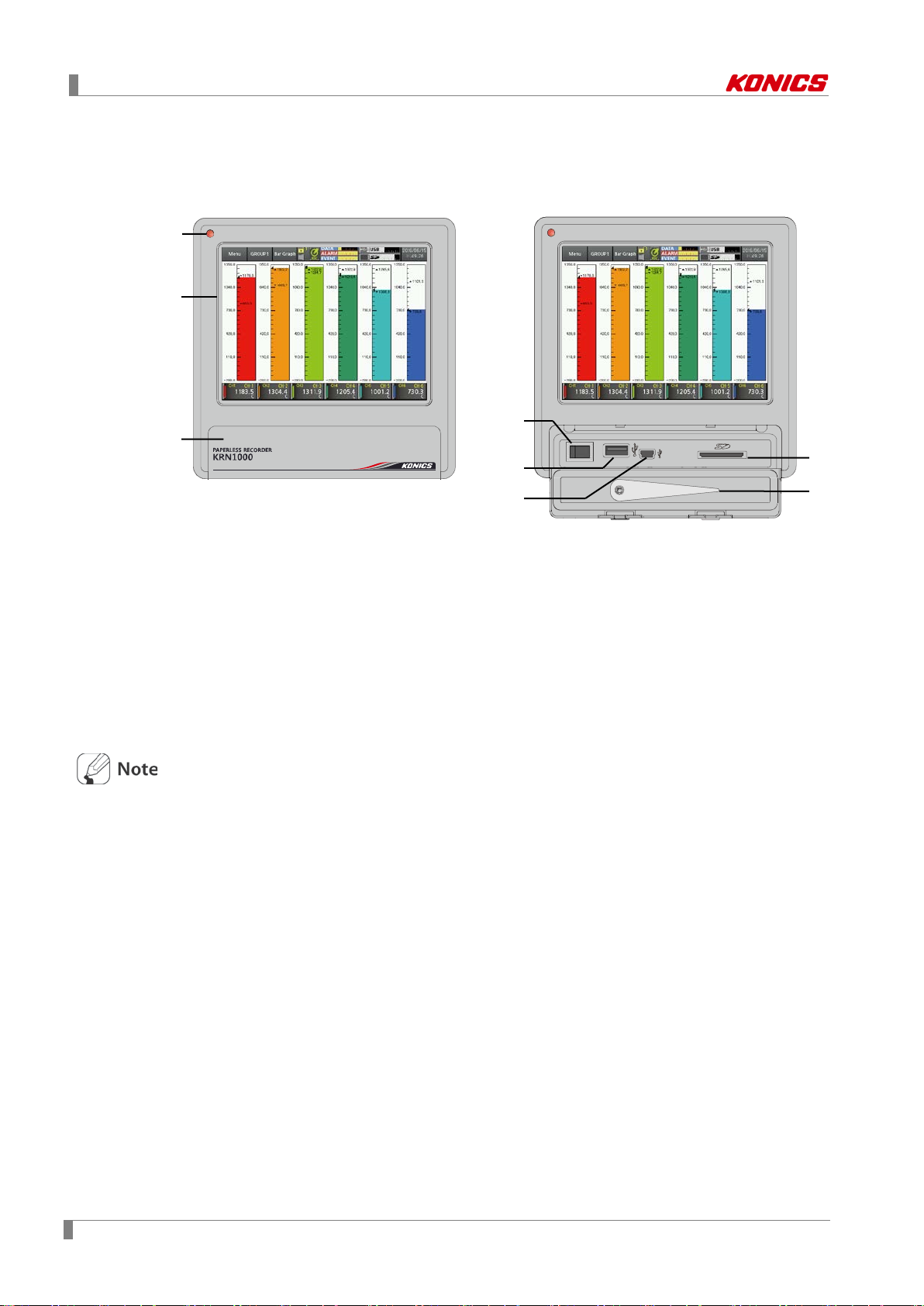
1 3 2
4
6
7
5
8
1.4 Unit description
1.4.1 Front part
1. Power indicator: Power turns ON and the red LED turns ON.
2. Screen: Measrued value is displayed as trand graph, bar bar graph, digital figures. (Refer to
‘6 Screen’)
3. Front cover: Open the front cover. There are power switch and, USB Host/Device, SD card
slot.
4. Power switch: Turn ON/OFF the power of KRN1000.
5. USB host port: Connect the USB memory.
It recognizes up to 32GB. When using extension cable, cable length should be up to 1.5m.
6. USB device port: Used for parameter settings.
7. SD card slot: SD card memory slot. It supports up to 32GB.
8. Stylus pen: Used for touching screen.
Do not connect the other USB devices except USB memory at USB host port.
14 © Copyright Reserved KONICS Co., Ltd.
1 Product Introduction
1
2 3 4
5
1.4.2 Rear part
1. Sensor input terminal: Connects universal input.
2. Ethernet port: Connector for ethernet cable. It communicates Modbus TCP.
3. RS422/485 port: Connects RS422/485 for Modbus RTU communication.
4. Option input/output port: Connects for option input/output (digita l in pu t (non-contact/ contact),
alarm output, power for transmitter).
5. Power input: Power connection (100-240VAC 50/60Hz)
© Copyright Reserved KONICS Co., Ltd. 15

1 Product Introduction
16 © Copyright Reserved KONICS Co., Ltd.

2 Specifications
2
2 Specifications
2.1 KRN1000
Power supply 100-240VAC 50/60Hz
Allowable voltage range 85 to 110% of rated voltage
Power consumption Max. 23VA
Display method 5.6 inch TFT Color LCD
Resolution
Screen
Number of input channels 4 / 8 / 12 / 16 channels
Universal input※1
Sampling period
Recording period 1 to 3600 sec
Internal memory Approx. 200MB
External memory SD / USB memory max. 32GB
Dielectric strength
Vibration
Insulation resistance Over 20MΩ (at 500VDC megger)
Noise immunity Square shaped noise by noise simulator (pulse width 1µs) ±2kV
Time accuracy Within ±2 min/year (available up to 2099)
Protection structure IP50 (front part)
Environm
ent
Adjusting
brightness
Input method Touch screen (Pressure sensitive type)
Mechanical 10 to 60Hz 4.9m/s
Malfunction 10 to 60Hz 1m/s2 in each X, Y, Z direction for 10 min
Ambient
※2
temperature
Ambient
humidity
640×480 pixels
3-level (Min/Standard/Max)
Temperature sensors (thermocouple, RTD),
Analog (voltage, current (shunt))
1 to 4-CH: 25ms/125ms/250ms, 5 to 16-CH: 125ms/250ms
(internal sampling period is average movement filter and alarm output
operation unit time)
2300VAC 50/60Hz for 1 min (between power terminals and case)
※Except ethernet and USB device
in each X, Y, Z direction for 1 hour
0 to 50℃, storage: -20 to 60℃
35 to 85%RH, storage: 35 to 85%RH
Approval
Weight※3 Approx. 1290 to 1400g (approx. 590 to 700g)
※1. For more information of universal input, refer to ‘2.2 Input/Output’.
※2. Environment resistance is rated at no freezing or condensation.
※3. The weight includes packaing. The weight in parenthesis is for unit only.
© Copyright Reserved KONICS Co., Ltd. 17
2 Specifications
Input/Output
type
(supplied current: approx. 190µA)
Thermocouple
B, C (W5), E, G, J, K, L, L (Russia), N, P, R, S, T, U
RTD
Warm-up time: Max. 30 min
Thermocouple
Resolution
16-bit
No-contact
input
ON: Residual voltage max. 1V
OFF: Leakage current max. 0.1mA
Short-circuit: Approx. 4mA
Mechanical: Min. 20,000,000 operations
(3A 250V AC, 3A 30V DC)
Power output
Modbus RTU
IEEE802.3 10 BASE-T /
IEEE802.3U 100 BASE-TX (Modbus TCP)
Universal input
method
2.2 Input/Output
Type
Universal input
Option
3
input/output
※
Input type
Input
impedance
Display
accuracy
Digital input
Alarm relay
output
Description
RTD
JPt100Ω, DPt100Ω, DPt50Ω, Cu100Ω, Cu50Ω
Voltage: ±60mV, ±200mV, ±2V, 1-5V, ±5V,
Analog
Current: 0-20mA, 4-20mA (measureable when
using 250Ω shunt resistance)
-1V-10V
1
※
Voltage (V): Approx. 205kΩ
RTD, Thermocouple, Voltage (mV): Min. 200kΩ
2
※
Analog
Contact input
Capacity
Life cycle
At room temperature (25±5℃): ±0.1% F.S.±1-digit
Out of room temperature: ±0.2% F.S.±1-digit
ON: Max. 1kΩ, OFF: Min. 100kΩ,
250VAC 3A, 30VDC 3A, 1 Form A (resistive load)
Electrical: 100,000 operations
24±2VDC, Max. 60mA
4
Built-in over current protection circuit
※
※It is recommended to use shielded cable over AWG 24.
Comm.
※
output
for
transmitter
RS422/485
5
Ethernet
USB Device USB V2.0 Full Speed (Modbus RTU)
※1. Current measurement and connecti on examples
Connect 250Ω shunt resistance and set analog input type 0-20mA (shunt) / 4-20mA (shunt).
It is available to measure 0-20mA / 4-20mA current.
shunt resistance connection
18 © Copyright Reserved KONICS Co., Ltd.

2 Specifications
※2. ◎ At room temperature (23℃ ± 5℃)
RTD Cu50Ω (-200≤T≤200): (±0.1% F.S. or ±1.5℃, select the higher one) ±1-digit
RTD DPt50Ω (-200≤T≤500): (±0.1% F.S. or ±1.5℃, select the higher one) ±1-digit
Thermocouple R, S, C, G type (0≤T≤100): (±0.1% F.S. or ±4.0℃, select the higher one)
±1-digit
Thermocouple U, T type (-100≤T≤400): (±0.1% F.S. or ±2.0℃, select the higher one)
±1-digit
Thermocouple B type, below 400℃: There is no accuracy standards.
All thermocouples, below -100℃: (±0.3% F.S. or ±4.0℃, select the higher one) ±1-digit
◎ Out of room temperature range
RTD Cu50Ω (-200≤T≤200): (±0.2% F.S. or ±3.0℃, select the higher one) ±1-digit
RTD DPt50Ω (-200≤T≤500): (±0.2% F.S. or ±3.0℃, select the higher one) ±1-digit
※3. Input/Output is different by option. Refer to ‘1.3 Ordering information’.
※4. For supplying power for transmitter, it is recommened to use shield cable to reduce noise.
※5. RS422/485, ethernet, USB device communication outputs are not used at the same time.
※If sensor input line is longer, it is recommended to use shield cable to reduce noise.
Before the wiring, turn OFF the unit.
Be sure that the polarity of power for transmitter. If not, it may cause produc t dam age.
When supplying the over voltage at sensor input, it may cause product damage.
© Copyright Reserved KONICS Co., Ltd. 19

2 Specifications
Temperatu re r an ge
K (CA)
TC-K
-200.0 to 1350.0
-328.0 to 2462.0
73.2 to 1623.2
J (IC)
TC-J
-200.0 to 800.0
-328.0 to 1472.0
73.2 to 1073.2
E (CR)
TC-E
-200.0 to 800.0
-328.0 to 1472.0
73.2 to 1073.2
T (CC)
TC-T
-200.0 to 400.0
-328.0 to 752.0
73.2 to 673.2
B (PR)
TC-B
100.0 to 1800.0
212.0 to 3272.0
373.2 to 2073.2
R (PR)
TC-R
0.0 to 1750.0
32.0 to 3182.0
273.2 to 2023.2
S (PR)
TC-S
0.0 to 1750.0
32.0 to 3182.0
273.2 to 2023.2
N (NN)
TC-N
-200.0 to 1300.0
-328.0 to 2372.0
73.2 to 1573.2
C (TT)
1
TC-C
0.0 to 2300.0
32.0 to 4172.0
273.2 to 2573.2
G (TT)
TC-G
0.0 to 2300.0
32.0 to 4172.0
273.2 to 2573.2
L (IC)
TC-L
-200.0 to 900.0
-328.0 to 1652.0
73.2 to 1173.2
L (Russian type)
TC-L_R
0.0 to 600.0
32.0 to 1112.0
273.2 to 873.2
U (CC)
TC-U
-200.0 to 400.0
-328.0 to 752.0
73.2 to 673.2
Platinel Ⅱ
TC-P
0.0 to 1350.0
32.0 to 2462.0
273.2 to 1623.2
Cu50Ω
CU50
-200.0 to 200.0
-328.0 to 392.0
73.2 to 473.2
Cu100Ω
CU100
-200.0 to 200.0
-328.0 to 392.0
73.2 to 473.2
JPt100Ω
JPT100
-200.0 to 600.0
-328.0 to 1112.0
73.2 to 873.2
DPt50Ω
DPT50
-200.0 to 600.0
-328.0 to 1112.0
73.2 to 873.2
DPt100Ω
DPT100
-200.0 to 850.0
-328.0 to 1562.0
73.2 to 1123.2
-60.00-60.00mV
±60mV
Resolution: 10µV
-200.00-200.00mV
±200mV
Resolution: 10µV
-2.000-2.000V
±2V
Resolution: 1mV
1.000-5.000V
1-5V
Resolution: 1mV
-5.000-5.000V
5V
Resolution: 1mV
-1.00-10.00V
-1V-10V
Resolution: 10mV
(shunt)
(shunt)
2.3 Input type and range
Input type Display
Thermocouple
※
2
※
3
※
℃ ℉
K
RTD
Voltage
-99999 to 99999
(display range depends on the
Analog
±
decimal point position.)
0-20mA
0-20mA
—
Current
(shunt)
4-20mA
4-20mA
—
※1. C (TT): Same as exisitng W5 (TT) type temperature sensor.
※2. G (TT): Same as existing W (TT) type temperature sensor.
※3. Russian L type temperature sensor is divided from general purpose L type.
20 © Copyright Reserved KONICS Co., Ltd.
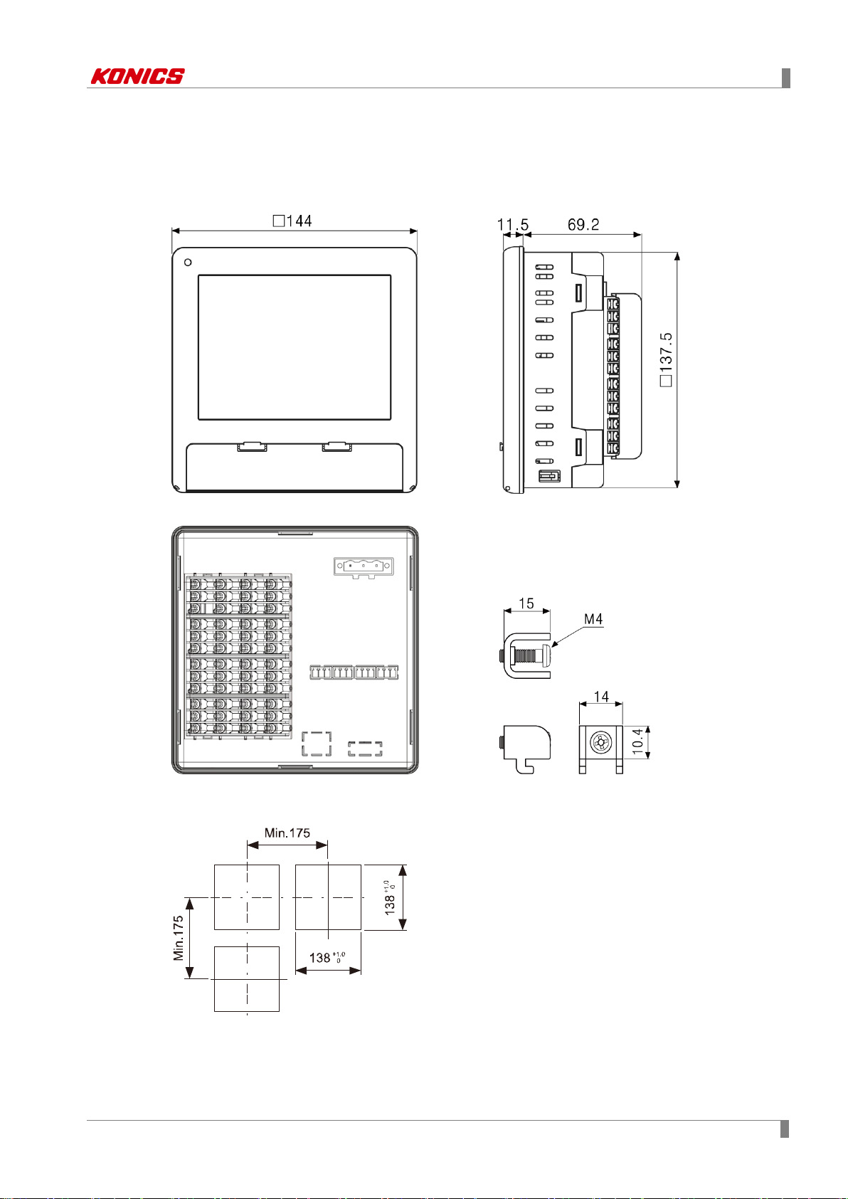
3 Dimensions
(Unit: mm)
3 Dimensions
3.1 KRN1000
3.2 Panel cut-out
※Use panel which is 1 to 5mm thickness.
© Copyright Reserved KONICS Co., Ltd. 21

3 Dimensions
22 © Copyright Reserved KONICS Co., Ltd.

4 Connections
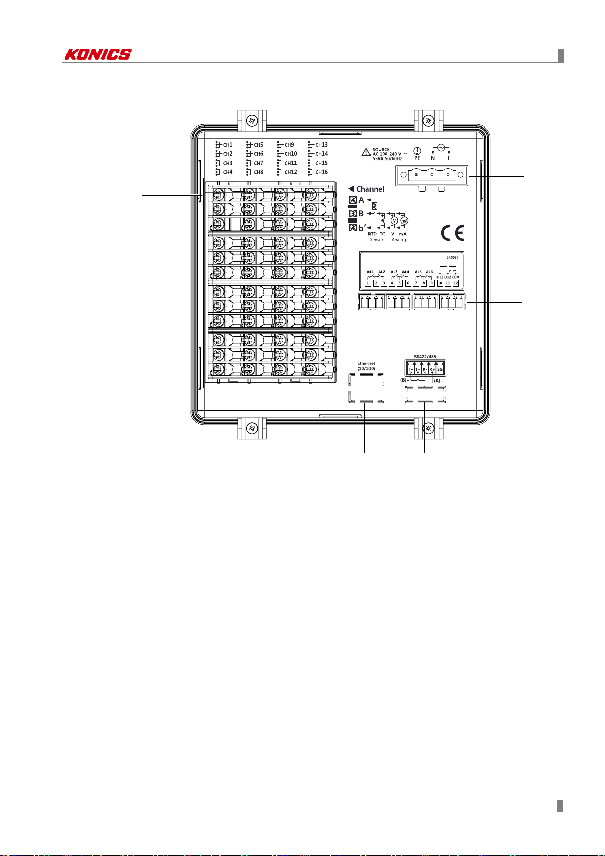
No
Descriptions
1
Connects universal input.
Connects option input/output (digital input (non-contact/contact), alarm output, power for
transmitter).
3
Connects communication output.
1 2 3
4 Connections
4.1 KRN1000
This figure is back side of KRN1000.
2
© Copyright Reserved KONICS Co., Ltd. 23
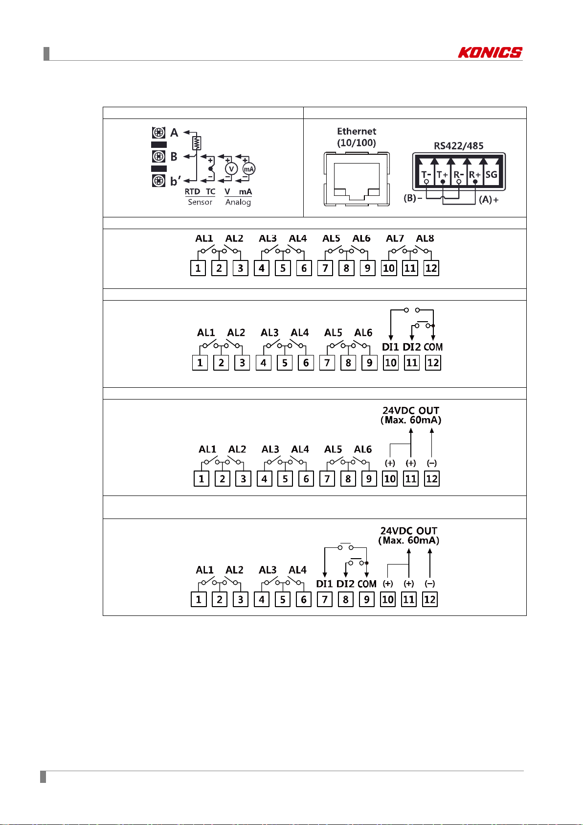
4 Connections
Universal input
Communication output
Option input/output 1 (alarm output 8 channels)
Option input/output 2 (alarm output 6 channels + digital input 2 channels)
Option input/output 3 (alarm output 6 channels + power for transmitter output)
Option input/output 4
(alarm output 4 channels + digital input 2 channel s + power for transmitter output)
4.2 Input/Output circuit
24 © Copyright Reserved KONICS Co., Ltd.

5 Installations
5 Installations
5.1 Environment
Install the unit in place where the below conditions are satisfied.
Place where ventilation is well
To prevent from malfunction and damage by overheating (use temperature range: 0 to
50℃), install this unit where ventilation is well.
In case installing several KRN1000, space each other by panel cut-out.
Place where vibration is not severe
If there is too much vibration, it may cause malfunction such as print error. For more
information about vibration, please refer to ‘2 Specifications’.
In case of temperature measurement with thermocouple temperature sensor at the place
where temperature is fluctuated, data error may occur. You should warm-up this unit over 30
min. to acquire accurate data before using it.
© Copyright Reserved KONICS Co., Ltd. 25
5 Installations
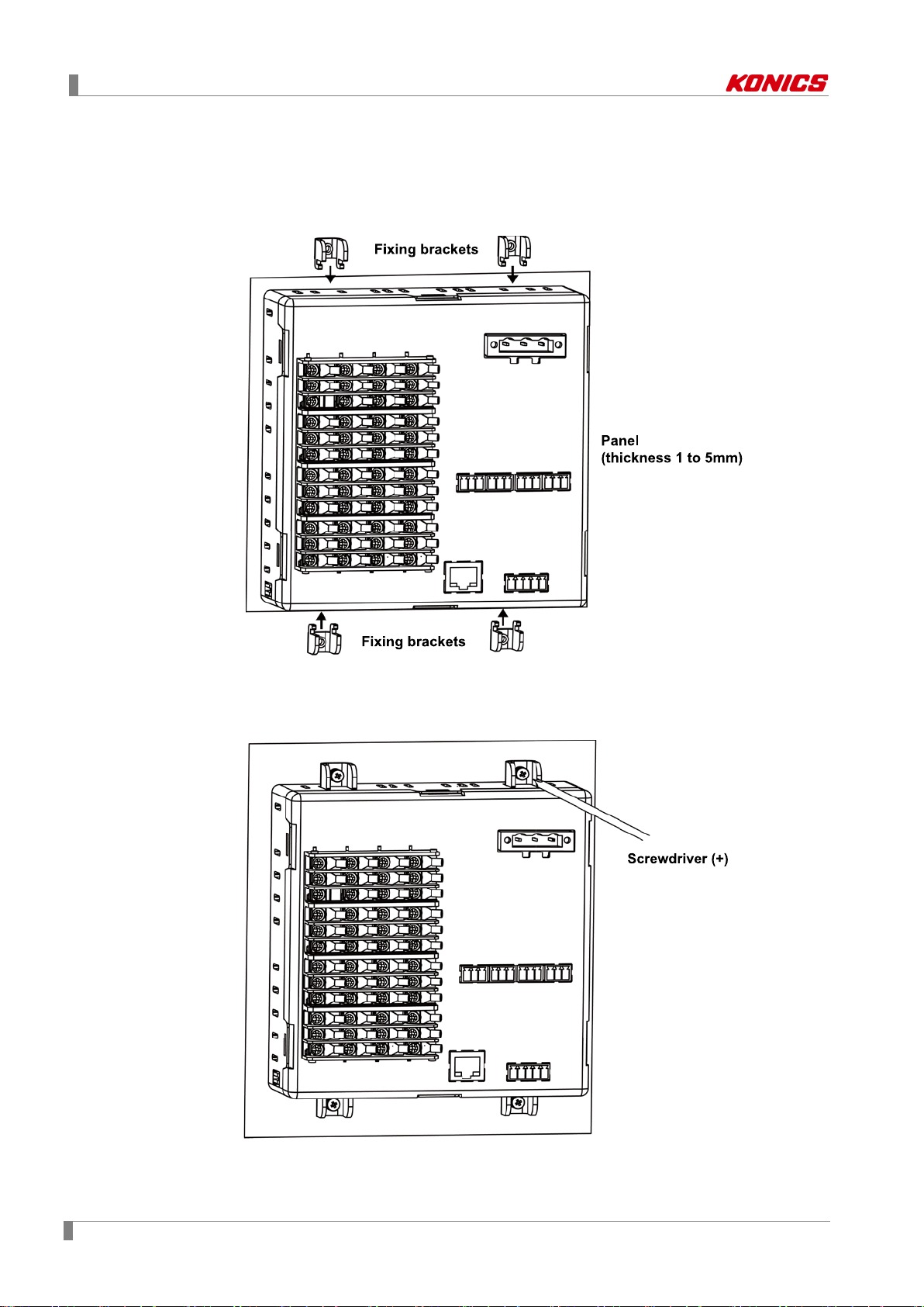
5.2 Installation Method
1st Install KRN1000 on the processed panel as panel cut-out diagram. Mount fixing
brackets on upper/lower parts.
2nd Tighten fixing brackets on upper/lower parts to fix on the panel with screwdriver (+)
with 0.4N•m torque.
26 © Copyright Reserved KONICS Co., Ltd.
 Loading...