


USER MANUAL
© Copyright Reserved KONICS Co., Ltd. i

ii © Copyright Reserved KONICS Co., Ltd.

Preface
Preface
Thank you for purchasing KONICS product.
Please familiarize yourself with the information contained in the Safety Precautions section
before using this product.
This user manual contains information about the product and its proper use, and should be kept
in a place where it will be easy to access.
© Copyright Reserved KONICS Co., Ltd. iii

User Manual Guide
User Manual Guide
Please familiarize yourself with the information in this manual before using the product.
This manual provides detailed information on the product's features. It does not offer any
guarantee concerning matters beyond the scope of this manual.
This manual may not be edited or reproduced in either part or whole without permission.
A user manual is not provided as part of the product package.
Visit our web site (www.konics.com) to download a copy.
The manual's content may vary depending on changes to the product's software and other
unforeseen developments within KONICS, and is subject to change without prior notice.
Update notice is provided through out homepage.
We contrived to describe this manual more easily and correctly. However, if there are any
corrections or questions, please notify us these on our homepage.
iv © Copyright Reserved KONICS Co., Ltd.
User Manual Symbols
Symbol
Description
User Manual Symbols
Supplementary information for a particular feature.
Failure to follow instructions can result in serious injury or death.
Failure to follow instructions can lead to a minor injury or product damage.
An example of the concerned feature's use.
※1
Annotation mark.
© Copyright Reserved KONICS Co., Ltd. v
Safety Precautions
Safety Precautions
Following these safety precautions will ensure the safe and proper use of the product and
help prevent accidents, as well as minimizing possible hazards.
Safety precautions are categorized as Warnings and Cautions, as defined below:
Warning
Caution
Failure to follow the instructions may lead to a serious injury
or accident.
Failure to follow the instructions may lead to a minor injury
or accident.
Fail-safe device must be installed when using the unit with machinery that may cause
serious injury or substantial economic loss. (e.g. nuclear power control, medical equipment,
ships, vehicles, railways, aircraft, combustion apparatus, safety equipment, crime/disaster
prevention devices, etc.)
Failure to follow this instruction may result in personal injury, fire, or economic loss.
The unit must be installed on a device panel before use.
Failure to follow this instruction may result in electric shock.
Do not connect, repair, or inspect the unit while connected to a power source.
Failure to follow this instruction may result in electric shock.
Check the terminal numbers before connecting the power source.
Failure to follow this instruction may result in fire or burning the unit.
Lithium battery is used in the unit. Do not disassemble or burn the unit.
Failure to follow this instruction may result in explosion.
Do not touch the unit and terminals after cut off the power within 30 sec.
Failure to follow this instruction may result in electric shock.
Ground PE terminal individually and ground cable should be over AWG16 (1.25 mm
Failure to follow this instruction may result in electric shock.
Do not insert any objects at the openings of the unit.
Failure to follow this instruction may result in electric shock or personal injury.
Do not disassemble or modify the unit. Please contact us if necessary.
Failure to follow this instruction may result in personal injury, fire, or economic loss.
Do not use the unit outdoors.
Failure to follow this instruction may result in shortening the life cycle of the unit, or electric
shock.
2
When connecting the power input and relay output cables, use AWG20 (0.05mm
) cables
and make sure to tighten the terminal screw bolt above 0.74N.m to 0.90N.m.
Failure to follow this instruction may result in fire due to contact failure.
Use the unit within the rated specifications.
Failure to follow this instruction may result in shortening the life cycle of the unit, or fire.
2
).
vi © Copyright Reserved KONICS Co., Ltd.

Safety Precautions
Do not use loads beyond the rated switching capacity of the relay contact.
Failure to follow this instruction may result in insulation failure, contact melt, contact failure,
relay broken, or fire.
When connecting magnet contact as relay contact output load, attach a surge absorber at
contact coil.
Failure to follow this instruction may result in product malfunction.
Do not use water or oil-based detergent when cleaning the unit. Use dry cloth to clearn the
unit.
Failure to follow this instruction may result in electric shock, or fire.
Do not use the unit where flammable or explosive gas, humidity, direct sunlight, radiant heat,
vibration, or impact may be present.
Failure to follow this instruction may result in fire or explosion.
Keep dust and wire residue from flowing into the unit.
Failure to follow this instruction may result in fire or product damage.
Check the polarity before connecting cables.
Failure to follow this instruction may result in fire or explosion.
Check the polarity of the measurement input contact before wiring the temperature sensor.
Failure to follow this instruction may result in fire or explosion.
Check the connection diagram of this manual before supplying power.
Failure to follow this instruction may result in fire.
Do not touch terminal during dielectric or insulation resistance test.
Failure to follow this instruction may result in electric shock.
Use insulation transformer and noise filter power for too much noise from the power. Attach
noise filter on the grounded panel, etc. Use short cables for noise filter output part and
power terminal of the unit.
Failure to follow this instruction may result in product damage, malfunction by surge.
If power line and input signal line are close each other, install line filter for noise protection
at power line and use shielded input signal line.
Do not control the alarm output or measure the data during firmware update. Failure to
follow this instruction may result in malfunction. Alarm output, contact input, data
measurement do not operate normally.
After completing firmware update, check the complete message and turn OFF to ON the
power.
All parameter setting values are reset after firmware update. It may not operate as same
way with before updating operation.
Use voltage output of transmitter power output only for transmitter power. Failure to follow
this instruction may result in output module damage.
Do not press the touch screen by sharp or hard objects with excessive force.
To prevent inductive noise, separate cables of the unit from high-voltage line, power line.
Do not install inductive noise or power line closely. It may cause measurement error.
Install the unit at well-ventilated place to prevent over-heat and give space over 30mm
against wall.
Install the unit vertically.
© Copyright Reserved KONICS Co., Ltd. vii

Safety Precautions
viii © Copyright Reserved KONICS Co., Ltd.

Table of Contents
Table of Contents
Preface .............................................................................................................................iii
User Manual Guide ......................................................................................................... iv
User Manual Symbols ...................................................................................................... v
Safety Precautions .......................................................................................................... vi
Table of Contents ............................................................................................................ ix
1 Product Introduction................................................................................. 11
1.1 Features ............................................................................................................. 11
1.2 Components and accessories ........................................................................... 12
1.2.1 Components ............................................................................................... 12
1.2.2 Accessories ................................................................................................ 12
1.3 Ordering information .......................................................................................... 13
1.4 Unit description .................................................................................................. 14
1.4.1 Front part .................................................................................................... 14
1.4.2 Rear part .................................................................................................... 15
2 Specifications ............................................................................................ 17
2.1 KRN1000 ........................................................................................................... 17
2.2 Input/Output ....................................................................................................... 18
2.3 Input type and range .......................................................................................... 20
3 Dimensions ................................................................................................ 21
3.1 KRN1000 ........................................................................................................... 21
3.2 Panel cut-out ...................................................................................................... 21
4 Connections .............................................................................................. 23
4.1 KRN1000 ........................................................................................................... 23
4.2 Input/Output circuit ............................................................................................. 24
5 Installations ............................................................................................... 25
5.1 Environment ....................................................................................................... 25
5.2 Installation Method ............................................................................................. 26
5.3 USB to Serial driver ........................................................................................... 27
5.3.1 Driver installation ........................................................................................ 27
5.3.2 Check the driver ......................................................................................... 28
6 Screen ........................................................................................................ 29
6.1 Initial booting screen .......................................................................................... 29
6.2 Screen description ............................................................................................. 30
6.2.1 Status display part ...................................................................................... 30
6.2.2 Measurement value display part ................................................................ 32
6.2.3 Graph ......................................................................................................... 33
6.2.4 Pop-up menu .............................................................................................. 37
6.2.5 Virtual keyboard ......................................................................................... 38
6.2.6 Color ........................................................................................................... 40
© Copyright Reserved KONICS Co., Ltd. ix

Table of Contents
7 Menu ........................................................................................................... 41
7.1 Display ............................................................................................................... 42
7.1.1 History ........................................................................................................ 42
7.1.2 File History ................................................................................................. 44
7.1.3 Group Setting ............................................................................................. 45
7.1.4 Touch Calibration ........................................................................................ 46
7.2 Status ................................................................................................................. 47
7.2.1 Alarm List.................................................................................................... 47
7.2.2 Event List .................................................................................................... 48
7.2.3 AO/DI Status ............................................................................................... 48
7.3 Input CH Info. ..................................................................................................... 49
7.3.1 Input/Display ............................................................................................... 49
7.3.2 Input Option ................................................................................................ 53
7.3.3 Alarm .......................................................................................................... 58
7.3.4 User Unit..................................................................................................... 60
7.4 Option Info. ........................................................................................................ 61
7.4.1 Alarm Output .............................................................................................. 61
7.4.2 Digital Input................................................................................................. 62
7.4.3 RS422/485 ................................................................................................. 63
7.4.4 Ethernet/USB ............................................................................................. 64
7.5 System Info. ....................................................................................................... 66
7.5.1 Date/Time ................................................................................................... 66
7.5.2 Reservation ................................................................................................ 67
7.5.3 Device......................................................................................................... 69
7.5.4 File .............................................................................................................. 70
7.5.5 Log In.......................................................................................................... 71
7.5.6 System Info. ............................................................................................... 72
7.6 Memory Info. ...................................................................................................... 73
7.6.1 Memory Management ................................................................................ 73
7.6.2 Internal Memory ......................................................................................... 74
7.7 Screen Capture .................................................................................................. 75
7.8 Log OFF/Power OFF ......................................................................................... 76
8 Integrated device management program (DAQMaster) ......................... 77
8.1 Overview ............................................................................................................ 77
8.2 Features ............................................................................................................. 78
8.3 Dedicated features for KRN1000 ...................................................................... 79
8.3.1 Record Backup ........................................................................................... 80
8.3.2 Check backup data ..................................................................................... 81
9 Troubleshooting ........................................................................................ 83
9.1 Error message ................................................................................................... 84
x © Copyright Reserved KONICS Co., Ltd.

1 Product Introduction
1 Product Introduction
1.1 Features
KRN1000 is paperless recorder with LCD method to save recording data at SD / USB memory.
It displays trend graph, bar graph, or digital figures at TFT Color LCD.
Via RS422/485, Ethernet or USB device communication, it is available to set parameters,
transfer data as data logger functions for user convienent.
It supports several communication method and various input/output functions. It also provides
easy and convient graphic user interface (GUI) applying graphic display.
5.6-inch color TFT LCD (640×480) touchscreen display with excellent readability and
intuitive control interface
Supports 27 input types (thermocouple, RTD, analog voltage and current[shunt])
4 / 8 / 12 / 16 input channel models available
Various communication methods (RS422/485, Ethernet, USB) standard
25 to 250 ms high-speed sampling, 1 to 3600 s recording cycle
200 MB internal memory and external memory support (SD/USB up to 32 GB)
Store and backup internal data to external memory (SD/USB)
9 different graph types available
Various option input/output available: digital input (contact/non-contact), alarm output,
transmitter power output
Compact, space-saving design (rear length: 69.2 mm)
© Copyright Reserved KONICS Co., Ltd. 11
1 Product Introduction
1.2 Components and accessories
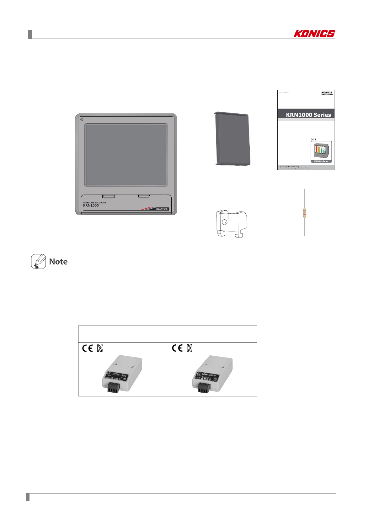
1.2.1 Components
LCD Touchscreen Paperless Recorder
Rear cover User manual
KRN
Before using KRN1000, check the components.
If any component is left out or damaged, contact our company or seller.
KONICS service center: +82-32-820-2356 to 7
1.2.2 Accessories
Communication converter
SCM-38I
(RS232C to RS485 converter)
Use Autonics SCM-38I or SCM-US48I as communication converter.
SCM-38I (RS232C/RS485 converter) and SCM-US48I (USB/RS485 converter) are same
appearance.
1000
Brackets: 4
SCM-US48I
(USB to RS485 converter)
Resistance (250Ω)
12 © Copyright Reserved KONICS Co., Ltd.
1 Product Introduction
Category
Description
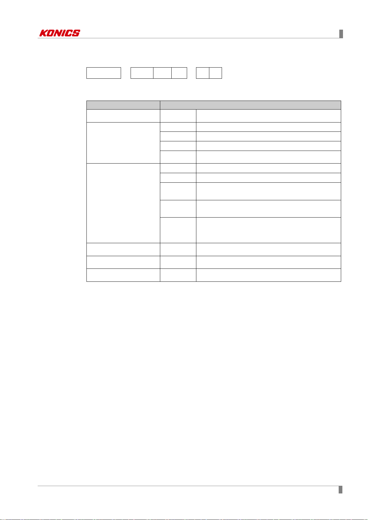
1.3 Ordering information
KRN1000 - 04 0 1
① ② ③ ④
⑤ ⑥
0 S
①Item
②Input channels
③Option input/output
④Communication output
KRN1000 Paperless recorder
04 4 channels
08 8 channels
12 12 channels
16 16 channels
0 None
1 Alarm relay output 8 channels
2
3
4
1 RS422/485 + Ethernet + USB Device
Alarm relay output 6 channels
+ Digital input 2 channels
Alarm relay output 6 channels
+ 24VDC power output for transmitter
Alarm relay output 4 channels
+ Digital input 2 channels
+ 24VDC power output for transmitter
⑤Power supply
⑥Case
0 100-240VAC 50/60Hz
S Standard panel installation type
© Copyright Reserved KONICS Co., Ltd. 13
1 Product Introduction
1 3 2
4
6
7
5
8
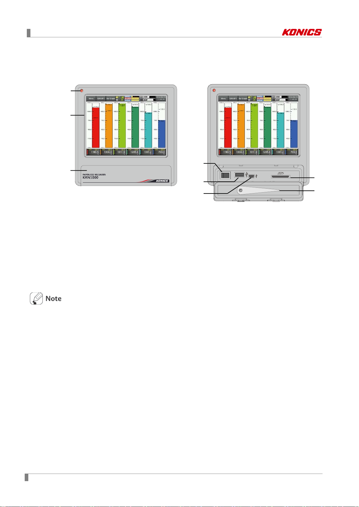
1.4 Unit description
1.4.1 Front part
1. Power indicator: Power turns ON and the red LED turns ON.
2. Screen: Measrued value is displayed as trand graph, bar bar graph, digital figures. (Refer to
‘6 Screen’)
3. Front cover: Open the front cover. There are power switch and, USB Host/Device, SD card
slot.
4. Power switch: Turn ON/OFF the power of KRN1000.
5. USB host port: Connect the USB memory.
It recognizes up to 32GB. When using extension cable, cable length should be up to 1.5m.
6. USB device port: Used for parameter settings.
7. SD card slot: SD card memory slot. It supports up to 32GB.
8. Stylus pen: Used for touching screen.
Do not connect the other USB devices except USB memory at USB host port.
14 © Copyright Reserved KONICS Co., Ltd.
1 Product Introduction
1
2 3 4
5
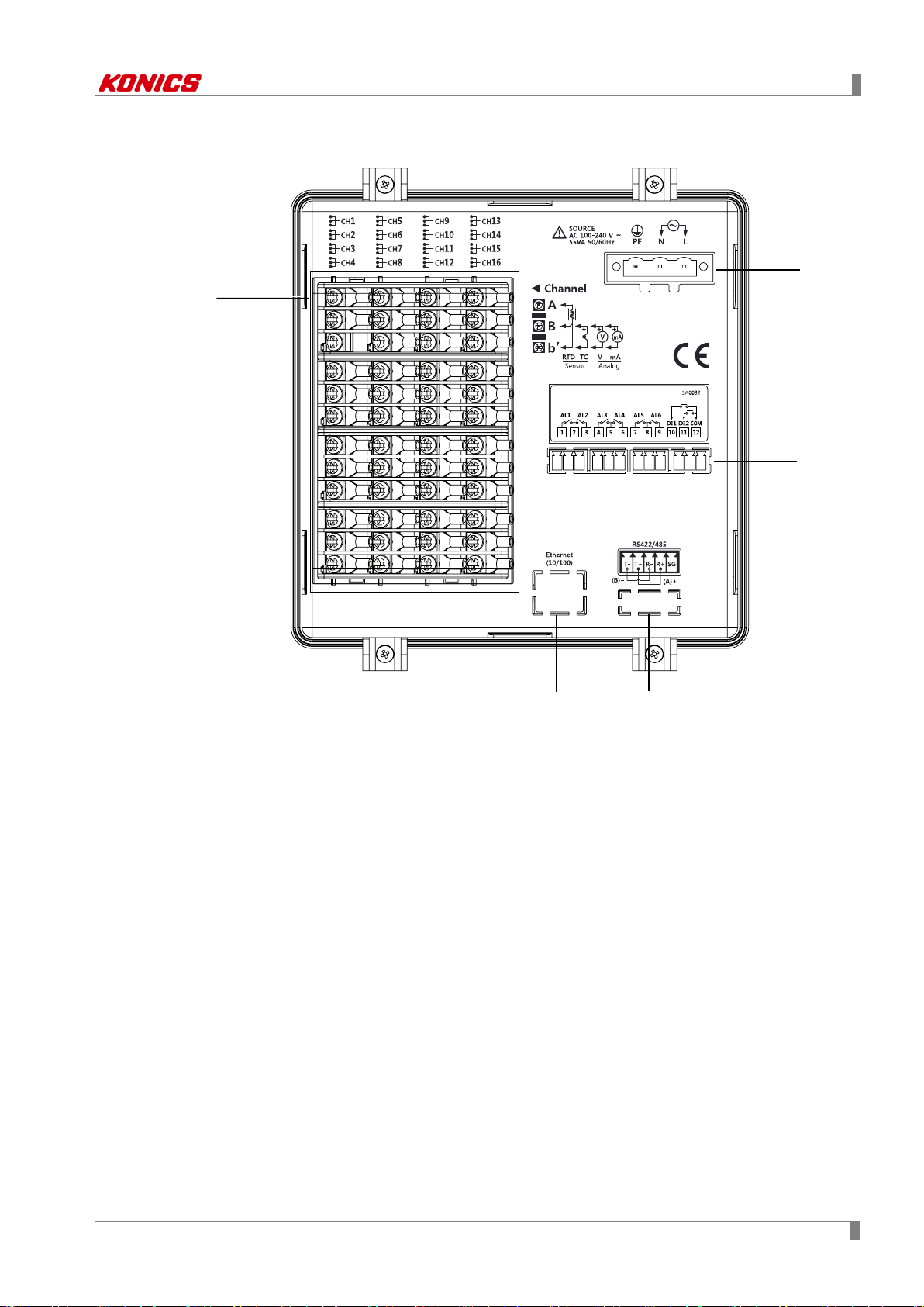
1.4.2 Rear part
1. Sensor input terminal: Connects universal input.
2. Ethernet port: Connector for ethernet cable. It communicates Modbus TCP.
3. RS422/485 port: Connects RS422/485 for Modbus RTU communication.
4. Option input/output port: Connects for option input/output (digita l in pu t (non-contact/ contact),
alarm output, power for transmitter).
5. Power input: Power connection (100-240VAC 50/60Hz)
© Copyright Reserved KONICS Co., Ltd. 15

1 Product Introduction
16 © Copyright Reserved KONICS Co., Ltd.
2 Specifications
2
2 Specifications
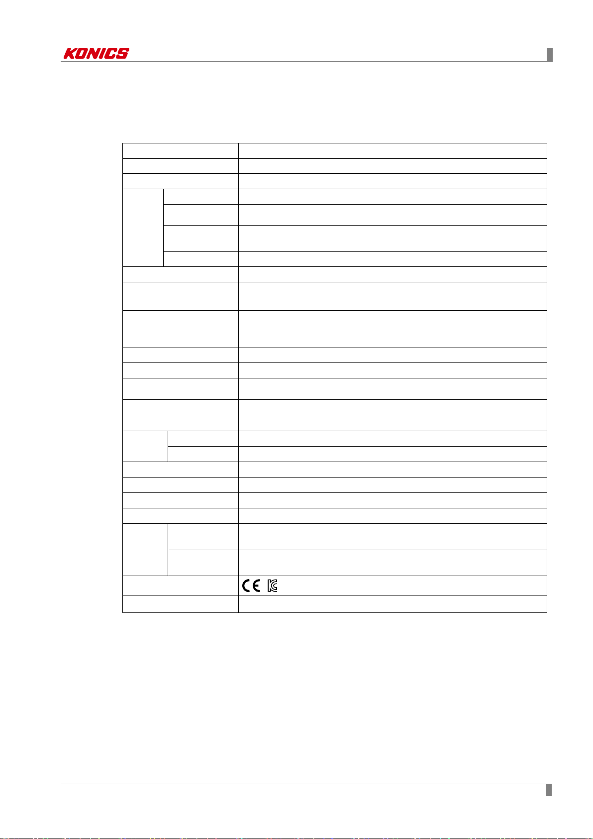
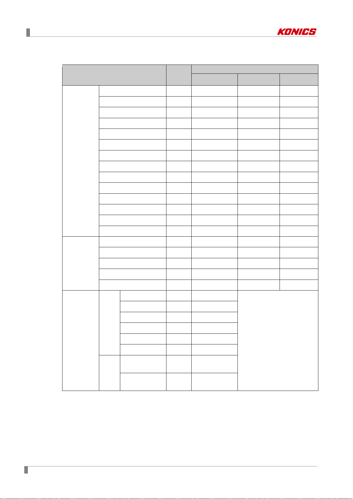
2.1 KRN1000
Power supply 100-240VAC 50/60Hz
Allowable voltage range 85 to 110% of rated voltage
Power consumption Max. 23VA
Display method 5.6 inch TFT Color LCD
Resolution
Screen
Number of input channels 4 / 8 / 12 / 16 channels
Universal input※1
Sampling period
Recording period 1 to 3600 sec
Internal memory Approx. 200MB
External memory SD / USB memory max. 32GB
Dielectric strength
Vibration
Insulation resistance Over 20MΩ (at 500VDC megger)
Noise immunity Square shaped noise by noise simulator (pulse width 1µs) ±2kV
Time accuracy Within ±2 min/year (available up to 2099)
Protection structure IP50 (front part)
Environm
ent
Adjusting
brightness
Input method Touch screen (Pressure sensitive type)
Mechanical 10 to 60Hz 4.9m/s
Malfunction 10 to 60Hz 1m/s2 in each X, Y, Z direction for 10 min
Ambient
※2
temperature
Ambient
humidity
640×480 pixels
3-level (Min/Standard/Max)
Temperature sensors (thermocouple, RTD),
Analog (voltage, current (shunt))
1 to 4-CH: 25ms/125ms/250ms, 5 to 16-CH: 125ms/250ms
(internal sampling period is average movement filter and alarm output
operation unit time)
2300VAC 50/60Hz for 1 min (between power terminals and case)
※Except ethernet and USB device
in each X, Y, Z direction for 1 hour
0 to 50℃, storage: -20 to 60℃
35 to 85%RH, storage: 35 to 85%RH
Approval
Weight※3 Approx. 1290 to 1400g (approx. 590 to 700g)
※1. For more information of universal input, refer to ‘2.2 Input/Output’.
※2. Environment resistance is rated at no freezing or condensation.
※3. The weight includes packaing. The weight in parenthesis is for unit only.
© Copyright Reserved KONICS Co., Ltd. 17
2 Specifications
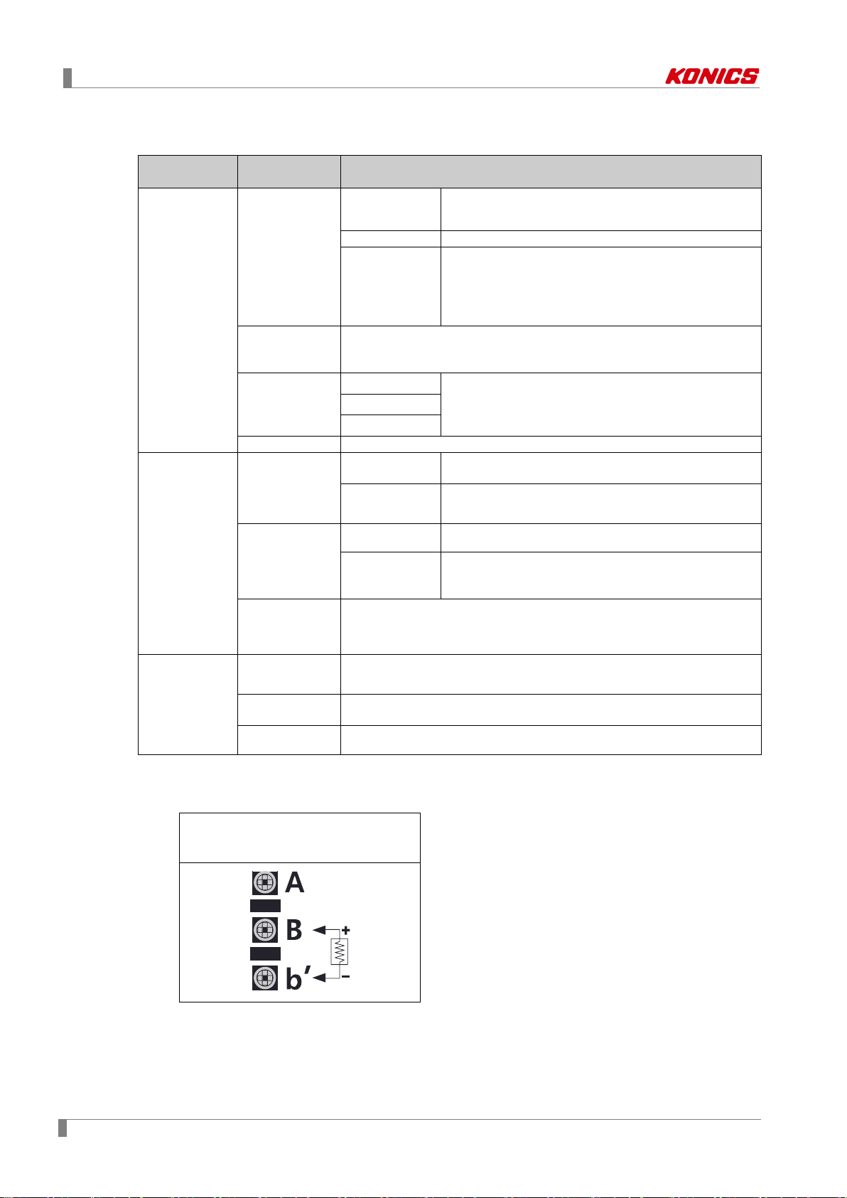
Input/Output
type
(supplied current: approx. 190µA)
Thermocouple
B, C (W5), E, G, J, K, L, L (Russia), N, P, R, S, T, U
RTD
Warm-up time: Max. 30 min
Thermocouple
Resolution
16-bit
No-contact
input
ON: Residual voltage max. 1V
OFF: Leakage current max. 0.1mA
Short-circuit: Approx. 4mA
Mechanical: Min. 20,000,000 operations
(3A 250V AC, 3A 30V DC)
Power output
Modbus RTU
IEEE802.3 10 BASE-T /
IEEE802.3U 100 BASE-TX (Modbus TCP)
Universal input
method
2.2 Input/Output
Type
Universal input
Option
3
input/output
※
Input type
Input
impedance
Display
accuracy
Digital input
Alarm relay
output
Description
RTD
JPt100Ω, DPt100Ω, DPt50Ω, Cu100Ω, Cu50Ω
Voltage: ±60mV, ±200mV, ±2V, 1-5V, ±5V,
Analog
Current: 0-20mA, 4-20mA (measureable when
using 250Ω shunt resistance)
-1V-10V
1
※
Voltage (V): Approx. 205kΩ
RTD, Thermocouple, Voltage (mV): Min. 200kΩ
2
※
Analog
Contact input
Capacity
Life cycle
At room temperature (25±5℃): ±0.1% F.S.±1-digit
Out of room temperature: ±0.2% F.S.±1-digit
ON: Max. 1kΩ, OFF: Min. 100kΩ,
250VAC 3A, 30VDC 3A, 1 Form A (resistive load)
Electrical: 100,000 operations
24±2VDC, Max. 60mA
4
Built-in over current protection circuit
※
※It is recommended to use shielded cable over AWG 24.
Comm.
※
output
for
transmitter
RS422/485
5
Ethernet
USB Device USB V2.0 Full Speed (Modbus RTU)
※1. Current measurement and connecti on examples
Connect 250Ω shunt resistance and set analog input type 0-20mA (shunt) / 4-20mA (shunt).
It is available to measure 0-20mA / 4-20mA current.
shunt resistance connection
18 © Copyright Reserved KONICS Co., Ltd.
2 Specifications
※2. ◎ At room temperature (23℃ ± 5℃)
RTD Cu50Ω (-200≤T≤200): (±0.1% F.S. or ±1.5℃, select the higher one) ±1-digit
RTD DPt50Ω (-200≤T≤500): (±0.1% F.S. or ±1.5℃, select the higher one) ±1-digit
Thermocouple R, S, C, G type (0≤T≤100): (±0.1% F.S. or ±4.0℃, select the higher one)
±1-digit
Thermocouple U, T type (-100≤T≤400): (±0.1% F.S. or ±2.0℃, select the higher one)
±1-digit
Thermocouple B type, below 400℃: There is no accuracy standards.
All thermocouples, below -100℃: (±0.3% F.S. or ±4.0℃, select the higher one) ±1-digit
◎ Out of room temperature range
RTD Cu50Ω (-200≤T≤200): (±0.2% F.S. or ±3.0℃, select the higher one) ±1-digit
RTD DPt50Ω (-200≤T≤500): (±0.2% F.S. or ±3.0℃, select the higher one) ±1-digit
※3. Input/Output is different by option. Refer to ‘1.3 Ordering information’.
※4. For supplying power for transmitter, it is recommened to use shield cable to reduce noise.
※5. RS422/485, ethernet, USB device communication outputs are not used at the same time.
※If sensor input line is longer, it is recommended to use shield cable to reduce noise.
Before the wiring, turn OFF the unit.
Be sure that the polarity of power for transmitter. If not, it may cause produc t dam age.
When supplying the over voltage at sensor input, it may cause product damage.
© Copyright Reserved KONICS Co., Ltd. 19
2 Specifications
Temperatu re r an ge
K (CA)
TC-K
-200.0 to 1350.0
-328.0 to 2462.0
73.2 to 1623.2
J (IC)
TC-J
-200.0 to 800.0
-328.0 to 1472.0
73.2 to 1073.2
E (CR)
TC-E
-200.0 to 800.0
-328.0 to 1472.0
73.2 to 1073.2
T (CC)
TC-T
-200.0 to 400.0
-328.0 to 752.0
73.2 to 673.2
B (PR)
TC-B
100.0 to 1800.0
212.0 to 3272.0
373.2 to 2073.2
R (PR)
TC-R
0.0 to 1750.0
32.0 to 3182.0
273.2 to 2023.2
S (PR)
TC-S
0.0 to 1750.0
32.0 to 3182.0
273.2 to 2023.2
N (NN)
TC-N
-200.0 to 1300.0
-328.0 to 2372.0
73.2 to 1573.2
C (TT)
1
TC-C
0.0 to 2300.0
32.0 to 4172.0
273.2 to 2573.2
G (TT)
TC-G
0.0 to 2300.0
32.0 to 4172.0
273.2 to 2573.2
L (IC)
TC-L
-200.0 to 900.0
-328.0 to 1652.0
73.2 to 1173.2
L (Russian type)
TC-L_R
0.0 to 600.0
32.0 to 1112.0
273.2 to 873.2
U (CC)
TC-U
-200.0 to 400.0
-328.0 to 752.0
73.2 to 673.2
Platinel Ⅱ
TC-P
0.0 to 1350.0
32.0 to 2462.0
273.2 to 1623.2
Cu50Ω
CU50
-200.0 to 200.0
-328.0 to 392.0
73.2 to 473.2
Cu100Ω
CU100
-200.0 to 200.0
-328.0 to 392.0
73.2 to 473.2
JPt100Ω
JPT100
-200.0 to 600.0
-328.0 to 1112.0
73.2 to 873.2
DPt50Ω
DPT50
-200.0 to 600.0
-328.0 to 1112.0
73.2 to 873.2
DPt100Ω
DPT100
-200.0 to 850.0
-328.0 to 1562.0
73.2 to 1123.2
-60.00-60.00mV
±60mV
Resolution: 10µV
-200.00-200.00mV
±200mV
Resolution: 10µV
-2.000-2.000V
±2V
Resolution: 1mV
1.000-5.000V
1-5V
Resolution: 1mV
-5.000-5.000V
5V
Resolution: 1mV
-1.00-10.00V
-1V-10V
Resolution: 10mV
(shunt)
(shunt)
2.3 Input type and range
Input type Display
Thermocouple
※
2
※
3
※
℃ ℉
K
RTD
Voltage
-99999 to 99999
(display range depends on the
Analog
±
decimal point position.)
0-20mA
0-20mA
—
Current
(shunt)
4-20mA
4-20mA
—
※1. C (TT): Same as exisitng W5 (TT) type temperature sensor.
※2. G (TT): Same as existing W (TT) type temperature sensor.
※3. Russian L type temperature sensor is divided from general purpose L type.
20 © Copyright Reserved KONICS Co., Ltd.
3 Dimensions
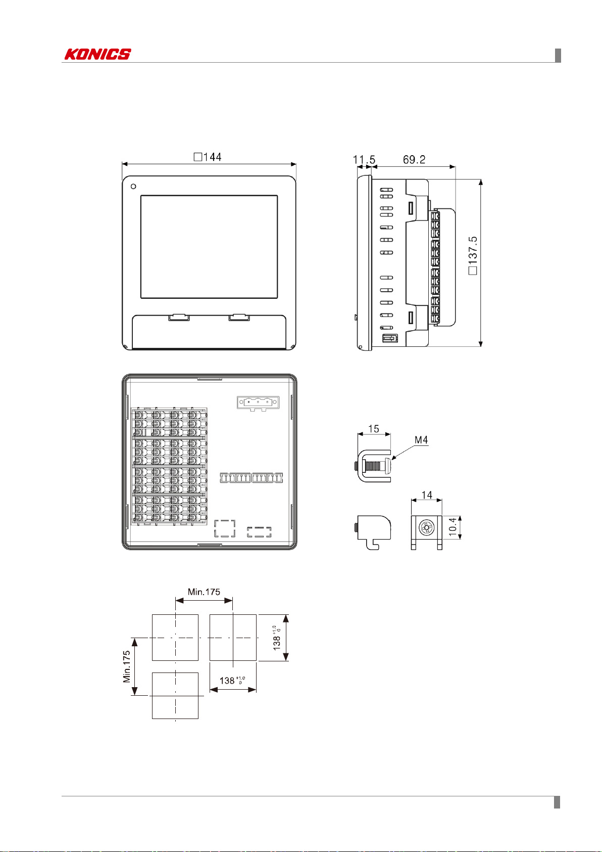
(Unit: mm)
3 Dimensions
3.1 KRN1000
3.2 Panel cut-out
※Use panel which is 1 to 5mm thickness.
© Copyright Reserved KONICS Co., Ltd. 21

3 Dimensions
22 © Copyright Reserved KONICS Co., Ltd.

4 Connections
No
Descriptions
1
Connects universal input.
Connects option input/output (digital input (non-contact/contact), alarm output, power for
transmitter).
3
Connects communication output.
1 2 3
4 Connections
4.1 KRN1000
This figure is back side of KRN1000.
2
© Copyright Reserved KONICS Co., Ltd. 23
4 Connections
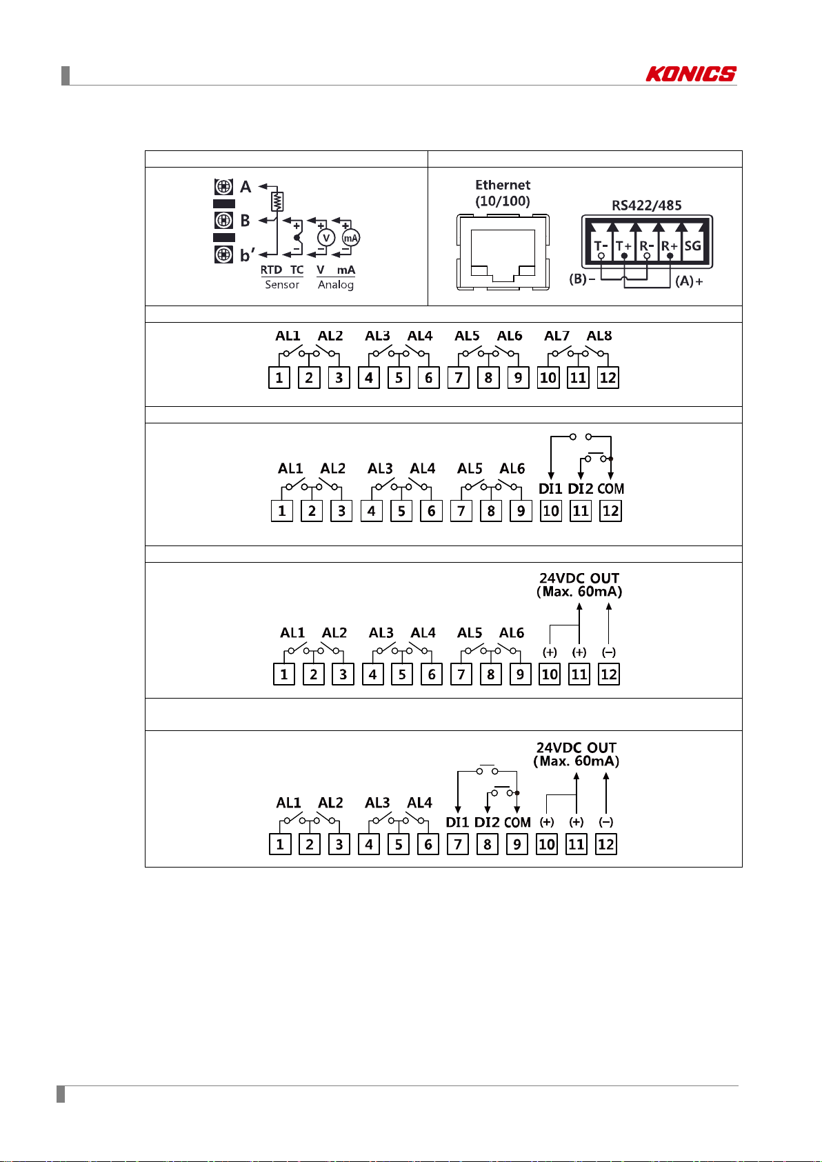
Universal input
Communication output
Option input/output 1 (alarm output 8 channels)
Option input/output 2 (alarm output 6 channels + digital input 2 channels)
Option input/output 3 (alarm output 6 channels + power for transmitter output)
Option input/output 4
(alarm output 4 channels + digital input 2 channel s + power for transmitter output)
4.2 Input/Output circuit
24 © Copyright Reserved KONICS Co., Ltd.

5 Installations
5 Installations
5.1 Environment
Install the unit in place where the below conditions are satisfied.
Place where ventilation is well
To prevent from malfunction and damage by overheating (use temperature range: 0 to
50℃), install this unit where ventilation is well.
In case installing several KRN1000, space each other by panel cut-out.
Place where vibration is not severe
If there is too much vibration, it may cause malfunction such as print error. For more
information about vibration, please refer to ‘2 Specifications’.
In case of temperature measurement with thermocouple temperature sensor at the place
where temperature is fluctuated, data error may occur. You should warm-up this unit over 30
min. to acquire accurate data before using it.
© Copyright Reserved KONICS Co., Ltd. 25
5 Installations
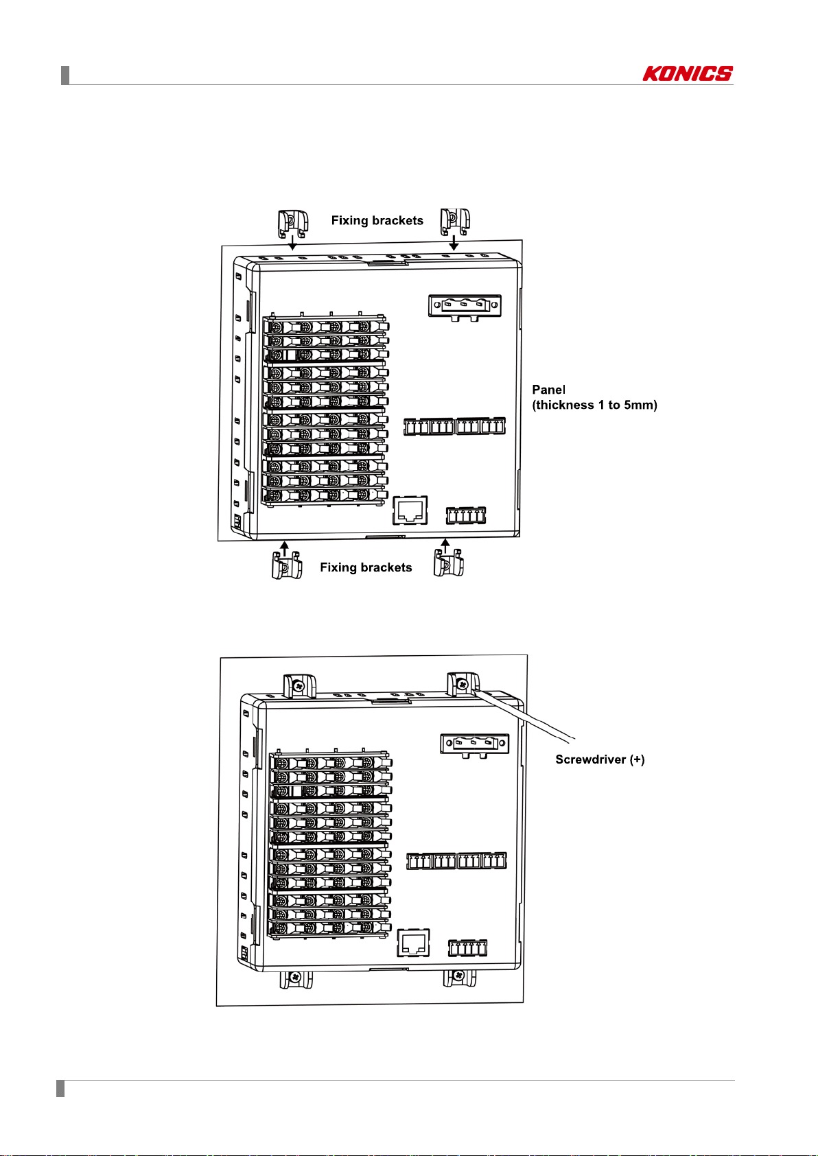
5.2 Installation Method
1st Install KRN1000 on the processed panel as panel cut-out diagram. Mount fixing
brackets on upper/lower parts.
2nd Tighten fixing brackets on upper/lower parts to fix on the panel with screwdriver (+)
with 0.4N•m torque.
26 © Copyright Reserved KONICS Co., Ltd.

5 Installations
5.3 USB to Serial driver
Install USB to serial driver which is applied for KRN100 sereis and connect DAQMaster and you
can set parameter setting.
Supporing operation system for USB to Serial driver is Windows XP, VISTA (32/64bit), 7
(32/64bit), 8 (32/64bit).
5.3.1 Driver installation
1st Visit our web site www.konics.com and download
'KRN1000_USB_To_Serial_Drivers.zip’ or visit
http://www.ftdichip.com/Drivers/VCP.htm and download the dedicated OS driver.
2nd Run CDM v2.xx.xx WHQL Certified.exe and install the driver.
(driver version may be different.)
© Copyright Reserved KONICS Co., Ltd. 27

5 Installations
3rd Connect the USB device port at KRN1000 front cover and PC USB port via USB
cable (A-Mini B 5-pin, 1.5m).
4th After recognizing the driver, the driver is automatically installed.
5.3.2 Check the driver
To check the driver, right click 'My computer' and select 'Properties' on pop-up menu. 'Device
Manager'' dialog appears. Check ‘Ports (COM & LPT)’ - 'USB To Serial Converter (COMx)'.
28 © Copyright Reserved KONICS Co., Ltd.

6 Screen
6 Screen
6.1 Initial booting screen
Below booting screens are initially displayed when power is supplied to KRN1000. These
screens progresses initial settings for KRN1000 to operate normally and checks inner system
memory.
If there is no error for inner system memory, booting is finished and KRN1000 operates normally.
Initial screen: Checking initial system memory error and processing module reset
If initial system memory error occurs,
If initial system memory error occurs, it does not operate normally.
Contact our company or seller.
Konics service center: +82-32-820-2356 to 7
© Copyright Reserved KONICS Co., Ltd. 29

6 Screen
Displays currently displayed group name.
group name and the set group name is displayed.
Select the displayed graph at the current screen.
vertical/horizontal mixed graph, digital group/all.
Displays at standard user mode.
(activated log-in function or log off status)
Displays at administor mode.
(activated log-in function and log-in as administor mode)
Displays at unlock.
(inactivated log-in function)
Status display
Measurement
part
6.2 Screen description
The screen consists of status display part and measurement value display part.
part
value display
6.2.1 Status display part
Section Icon Description
Menu Displays menu.
1
2
1
※
3
Esc Moves from menu to current screen.
Home Moves to main screen.
Group
Graph
Touch the icon and select the group. You can set the
Select one among bar graph, vertical/horizontal trend
graph, divided vertical/horizontal trend graph,
Lock
2
※
4
Lock Setting
Unlock
30 © Copyright Reserved KONICS Co., Ltd.

6 Screen
Data Record
Space
Alarm Record
Space
Event Record
Space
USB Memory No
Connection
USB Memory No
Save
Displays when internal memory data does not save at
USB memory.
USB Memory
Save
Displays when internal memory data saves at USB
memory.
SD Card No
Connection
SD Card
No Save
Displays when internal memory data does not save at SD
card.
Section Icon Description
No Alarm Displays at no alarm.
Alarm Displays when alarm occurs.
Internal Memory
Record
5
Internal Memory
No Record
6
7
Displays when recording measurement value of each
channel at internal memory.
Displays when displaying measurement value and no
recording it at internal memory.
Displays usage details of data recording space.
Displays empty space of alarm data memory.
Displays empty space of event data memory.
Displays when USB memory is not connected.
Displays when SD card is not connected.
SD Card Save Displays when internal memory data saves at SD card.
Displays date and time.
8
Date/Time
If summer time is set, "(s)" marks in front of time.
※1. For more information about screen graph, refer to ‘6.2.3 Graph’.
※2. For more information about lock and unlock, refer to ‘7.5.5 Log In’.
© Copyright Reserved KONICS Co., Ltd. 31

6 Screen
No
Item
Descriptions
2
1
6.2.2 Measurement value display part
Measurement value of each channel is displayed as graph and digital number.
One screen displays 6 channels and channel roation is maually or automatically setable.
For more information about channel roation and time, refer to ‘7.1.3 Group Setting’.
Measurement
1
value graph of
each channel
Measurement
value digital
2
number of each
channel
Displays the measurement value of each channel as graph.
Displays the measurement value of each channel as digital number.
32 © Copyright Reserved KONICS Co., Ltd.

6 Screen
6.2.3 Graph
Select the display graph at current screen. Touch the red square area to select the graph style.
The supported graphs are as below.
Bar graph
Vertical trend graph (V Trend)
© Copyright Reserved KONICS Co., Ltd. 33

6 Screen
Horizontal trend graph (H Trend)
Divided vertical trend graph (DV Trend)
The upper area is for real-time measurement value as vertical trend graph and the lower
area is for all records from start as vertical trend graph.
The lower area is available only when recording status.
Divided horizontal trend graph (DH Trend)
The right area is for real-time measurement value as horizontal trend graph and the left
area is for all records from start as horizontal trend graph.
The left area is available only when recording status.
34 © Copyright Reserved KONICS Co., Ltd.

6 Screen
Vertical mixed graph (V Mixed)
Measurement value of each channel is displayed as bar graph and vertical trend graph.
Horizontal mixed graph (H Mixed)
Measurement value of each channel is displayed as bar graph and horizontal trend graph.
Digital group
One screen displays measurement values of 6 channels.
© Copyright Reserved KONICS Co., Ltd. 35

6 Screen
All digitals
One screen displays measurement values of all channels.
36 © Copyright Reserved KONICS Co., Ltd.

6 Screen
No
Item
Descriptions
6.2.4 Pop-up menu
Touch the red square area at main screen and pop-up menu appears.
Starts recording the measurement value on the current screen.
1 Record
2 File
3 Remove Remove the installed external SD/USB memory.
Touch the Stop to stop the recording.
(when stop the recording during recording, data is not saved.)
- Move/Copy: Moves/Copies the saved log file of internal memory to
extenral memory.
-Record Info.: Displays saving path, log record period of currently
recording data.
© Copyright Reserved KONICS Co., Ltd. 37

6 Screen
No
Icon
Descriptions
6.2.5 Virtual keyboard
You can enter setting value via vertual keyboard.
Virtual keyboard is activated automatically when setting value enters. For entering numbers,
number virtual keyboard is activated.
Only English is supported to enter.
1
2
3
4
5
Displays keyboard input status.
Select English capital/small letter, number or sign.
Deletes the entered charaters.
Saves the entered characters.
Cancels the entered characters.
Enterable characters are as below.
English capital letters
38 © Copyright Reserved KONICS Co., Ltd.

6 Screen
English small letters
Signs and numbers
Number virtual keyboard
© Copyright Reserved KONICS Co., Ltd. 39

6 Screen
6.2.6 Color
Select the color.
KRN1000 supports 23 colors. Set the pen color, or background color of each group.
40 © Copyright Reserved KONICS Co., Ltd.

7 Menu
7 Menu
Touch the menu at top-left screen and menu displays. Menu consists as below.
© Copyright Reserved KONICS Co., Ltd. 41
7 Menu
No
Item
Descriptions
7.1 Display
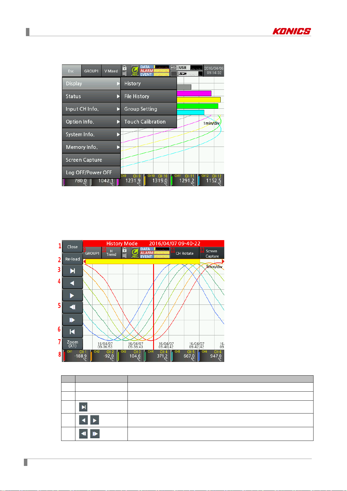
7.1.1 History
You can open the log file which is recording to check the dedicated data history (measurement
value and whole trend).
Move the history axis (vertical red line) at the desired time to check the dedicated data of each
channel.
42 © Copyright Reserved KONICS Co., Ltd.
1 Close Moves to the main screen.
2 Re-load Re-loads the measured data.It updates the latest data.
3
4
5
,
,
Moves to the latest data point of log file.
Moves the history axis to back/forward for 1 sec.
Moves the history log data to two-thirds back/forward of the screen.

7 Menu
No
Item
Descriptions
6
7 Zoom
8 CH Display
9
10 Graph
11 CH Rotate
GROUP□
Moves the old data point of log file.
Zooms in/out the screen from 1 to 1200 magnifications.
Touch the desired channel not to be displayed. The data value of the
channel is displayed as gray color.
Select the group.
You can change the group name. Refer to ‘7.1.3 Group Setting ‘.
Displays the desired graph as horizontal trend (H Trend) → divided
horizontal trend (DH Trend) →vertical trend (V Trend) → divided vertical
trend (DV Trend) graph by touching the icon.
Rotate the displayed 6 channels per one screen.
CH1/2/3/4/5/6 → CH7/8/9/10/11/12 → CH13/14/15/16
Save the current screen.
12 Screen Capture
Check the currently recording data history.
When recording stops, error message appears.
© Copyright Reserved KONICS Co., Ltd. 43

7 Menu
No
Item
Descriptions
Set group and channel information of the saved log file.
Displays each channel information such as tag name, input type,
7.1.2 File History
You can open the saved log file to check the dedicated data history (measurement value and
whole trend).
Move the history axis (vertical red line) at the desired time to check the dedicated data of each
channel.
File history screen is added group setting, channel information from history screen.
1 Group
2 Channel Info.
For more information about group setting, refer to ‘7.1.3 Group Setting’.
Setting method and details are same.
low/high-limit scale.
44 © Copyright Reserved KONICS Co., Ltd.

7 Menu
No
Item
Descriptions
Moves group. Touch “Group 1” or
to select the desired
group.
Main screen graph displays only 6 channels’ data.
the screen)
Displays group name.
Touch the name and change the group name via the virtual keyboard.
4
No. of CHs
Displays the set number of channels.
5
Background
Set the group background color via the color select dialog box.
Pen1-4/ 5-8
/9- 12/13-16
7.1.3 Group Setting
It sets for group and channel information.
You can set the max. 16 channels according to input channels.
Input channel is available to set duplicated to one or several groups. Set the channel to each
group and pen color.
Groups are up to 6.
1 Group
2 CH Rotation Time
,
Set the channel automatical rotation time.
Setting range: 0 to 3600s. (0: changing channels manually by touching
3 Name
6
7
Pen □
Set the channel, color, line style, min./max. value by each pen.
Min./Max. value of each channel is input range of the input type.
For more information, refer to ‘2.3 Input type and range’.
© Copyright Reserved KONICS Co., Ltd. 45

7 Menu
7.1.4 Touch Calibration
It corrects touch input via pointer calibration.
When starting touch calibration, total 5 points are displays one by one. Touch the point and
calibrate it. For more accurate touch, it is recommended to use a stylus pen.
If touch calibration is wrong, re-boot the unit as initial system value.
Touch the right-below area over than twice of the initial booting screen.
46 © Copyright Reserved KONICS Co., Ltd.

7 Menu
7.2 Status
7.2.1 Alarm List
It displays occurring alarm(channel, alarm type, relay, start/end time) during operation.
Alarm list displays alarm channel, type, relay, start/end time of occuring alarms. You can save or
delete the alarm list. Alarm list is saved as *.csv file format.
When turing OFF power of KRN1000 while alarm occurs, end time is displayed as "0000-00-00
00:00:00".
Touch ‘History’ to check the data of alarm occuring point as horizontal trend/vertical trend/divided
horizontal trend/divided vertical trend graph.
Divided trend graph is displays divided screen to compare and check different time of the one file.
When recording starts/stops several times from starting to completing alarm, several log files are
created.
If there are several log files from starting alarm to end alarm, it displays the history of first log file
which includes alarm start time.
© Copyright Reserved KONICS Co., Ltd. 47

7 Menu
No
Item
Descriptions
- Alarm No: Displays alarm output number.
alarms.
7.2.2 Event List
It displays occurring event (event message, occurrence time) during operation.
You can save or delete the event list. Event list is saved as *.csv file format.
Event message displays occuring event during device operation such as device power ON/OFF,
record start/stop, or external memory recognization, etc.
7.2.3 AO/DI Status
It displays alarm output and digital input status.
Alarm Output
1
Status
2 Digital Input Status
48 © Copyright Reserved KONICS Co., Ltd.
- Status: Displays alarm output ON, OFF status.
- Alarm CH: Displays the channel occuring alarm.
If alarms occur at several channels, it displays the number of occuring
- DI No.: Displays digital input number.
- Status: Displays digital input ON, OFF status.
- Type: Displays the set digital input.
For more information about digital input, refer to ‘7.4.2 Digital Input’.

7 Menu
No
Item
Descriptions
Copies the other channels parameters of the same group.
Select the channel to be copy.
Set the input type. Input types are total 27: thermocouple, RTD, voltage, current
(shunt). For more information, refer to ‘2.3 Input type and range’.
In case of temperature sensor input, set the low-limit graph scale value within
In case of analog input, it displays low-limit input value.
5
High-Limit
In case of temperature sensor input, set the high-limit graph scale value within
7.3 Input CH Info.
It sets input type of each channel, option, alarm, user unit.
During memory recording, you cannot set or change input channel settings.
7.3.1 Input/Display
1 Channel
2 Copy
Moves channel. Touch ‘CH1’ or
to change the channel.
3 Input Type
Low-Limit
Graph
4
Scale/
Low-Limit
Input
© Copyright Reserved KONICS Co., Ltd. 49
the input range.
Setting range: Min. value of input range to high-limit graph scale value–F.S. 5%
E.g.) In case of TC-K input, -200.0 to 1350.0℃ of input range, and setting range
is -200.0 to 1272.5℃. (-F.S.=77.5)

7 Menu
No
Item
Descriptions
Graph
the input range.
In case of analog input, it displays high-limit input value.
- Temperature sensor input: 0, 0.0
(set the decimal point position for the scale value)
7
Tag Name
Set the channel name.
Low-Limit
Scale
High-Limit
Scale
Display
- Analog input: 72 display units are available. When not using unit, select blank.
Scale/
High-Limit
Input
Setting range: Low-limit graph scale value+F.S. 5% to Max. value of input range
E.g.) In case of TC-K input, -200.0 to 1350.0℃ of input range, and setting range
is -122.5 to 1350℃. (+F.S.=77.5)
6 Point
8
9
10
Unit
2
※
(set the decimal point for the measurement value)
- Analog input: 0, 0.0, 0.00, 0.000, 0.0000
Set the desired display value based on the measurement value.
1
It is activated only for analog (voltage, current (shunt)) input type.
※
- Temperature senosr input: Temperature units, ℃, ℉, ˚K are available.
※1. As below figure, for example, measured input values are ‘a’ and ‘b’ and the desired display
values are ‘A’, and ‘B’. In this case, about the input ‘a’ and ‘b’, it displays a=A, b=B as
linearly.
You can change display value about min./max. input value of the measurement value.
50 © Copyright Reserved KONICS Co., Ltd.

7 Menu
In case of input type, -60 to +60mV
Low Scale (low-limit scale value)=0.0, High Scale (high-limit scale value)=Set as 10.0, 20.0,
30.0, -20.0
Low Scale (low-limit scale value)=20.0, High Scale (high-limit scale value)=Set as -20.0
Low Scale (low-limit scale value)=-20.0, High Scale (high-limit scale value)=Set as 20.0
© Copyright Reserved KONICS Co., Ltd. 51

7 Menu
10
ml
26
cd
42
VA
58
mmH2O
11 t 27
lm
43 W 59
bar
12
Val
28
cd/m2
44
kW
60
Torr
15
barrel
31
m2/s
47
kVar
63
psi
16 - 32
cp
48
MVar
64
User0
※2. Supported display unit
No Unit No Unit No Unit No Unit No Unit
1 °C 17 % 33 V 49 mA
2 °F 18 Wt% 34 mV 50 A
3 °K 19 mass% 35 μV 51 kg/cm2
4 Kcal/m3 20 Vol% 36 kV 52 P
5 Kcal 21 ppm 37 Ω 53 kPa
6 cal 22 ppb 38 mΩ 54 MPa
7 j 23 mol 39 μΩ 55 N/m2
8 Btu 24 Space 40 s 56 N/mm2
9 l 25 lx 41 μs 57 inH2O
13 lb 29 rpm 45 MW 61 mmHg
14 oz 30 Hz 46 Var 62 mmAq
65 User1
66 User2
67 User3
68 User4
69 User5
70 User6
71 User7
72 User8
73 User9
In case of the complicated unit such as kg/cm
2
, screen quality may not be good.
52 © Copyright Reserved KONICS Co., Ltd.

7 Menu
No
Item
Descriptions
Special
Displays the applied measurement value as the set special function.
Two Unit is activated only for 4-20mA (shunt) input type.
3
Ref CH
Corrects error from input (thermocouple, RTD, voltage, current (shunt)), not
(depending on the set decimal point, the range is different.)
Adjusts high-limit error by regulating display value which is about
measurement value or applied scale.
Set the recording method of measured data by each channel.
Setting
value
Instant
Saves measurement value at every recording cycle.
Saves the average value of sampling measurement value
during recording cycle.
Saves the min. value of sampling measurement value during
recording cycle.
Saves the max. value of sampling measurement value during
recording cycle.
In some applications the fluctuating measured input causes the display value
may be different with input value.
No. of
7.3.2 Input Option
1 Channel
2
Func.
1
※
4 Two Unit
5 Input Bias
2
6
7
※
Span
Record
Method
8 Digital Filter
Moves channel. Touch ‘CH1’ or
to change the channel.
Depending on input type, applicable special functions are different.
Setting range
- Temperature sensor input: None, Difference (deviation)
- Analog input: Linear, Root, Square, Two Unit
from the recorder.
Setting range: -9999 to 9999, -999.9 to 999.9, -99.99 to 99.99, -9.999 to 9.999
-0.9999 to 0.9999
Descriptions
Average
Min
Max
to fluctuate. In this case accurate display/record is disable. This function is
able to make display value stable by input digital filter. Input digital filter uses
moving average method. It does not affet to display period but display value
Digital
9
Filters
3
※
menu is activated.
Setting range: 1 to 128
Set the number of samplings which apply to digital filter. Set Filter type and this
© Copyright Reserved KONICS Co., Ltd. 53

7 Menu
No
Item
Descriptions
In case of temperature sensor input type, set the alarm type and option for
Setting
value
Displays BURN after the display value increases as up scale
when input break.
Down
Scale
Displays BURN after the display value decreases as down
scale when input break
input break.
(it does not operate for analog (voltage, current (shunt)) input type.)
Descriptions
10
Burn-out
Action
None When input break, it displays BURN.
Up Scale
※1. Below pattern graph appears comparing the values which are appling liner, root, square for
analog input.
Low-limit input: -5 V, High-limit input: +5 V, Low-limit scale: -1000, High-limit scale: 1000
(a) Difference (deviation)
It is available to set for temperature sensor (Thermocouple, RTD) input type. It displays the
deviation of the measurement value of reference channel.
(display value = the measurement value of standard channel –the measurement value of
reference channel)
The channels which input type is analog (voltage, current (shunt)) cannot be as reference
channel. If reference channel is not set, it displays the measurement value of standard
channel.
If any one of reference channel, or standard channel is break (BURN), high-limit value
(HHHH), low-limit value (LLLL) status, it displays as correspond value. If the set reference
channel uses difference function, it displays the calcuated value based on actual
measurement value, not display value of reference channel.
54 © Copyright Reserved KONICS Co., Ltd.

7 Menu
(b) Linear
It applies low-limit scale and high-limit scale to low-limit input value and high-limit input value
and displays this values.
In case of low-limit input value: -5 V, high-limit input value: +5V, low-limit scale: -1000, highlimit scale: 1000,
and current input value is 2V, display value is 400.
Display value
=
(
400 =
×
7
× 2000 1000
10
Input value Low limit input value
High limit input value Low
limit input value
High limit scale Low limit scale)+ Low limit scale
(c) Root
In case voltage, current input type, this function calculates by Root () for the input value.
Differential pressure signal of differential pressure flow meter is calculated by Root (
) for
the desired pressure flow. This function is used for measuring flux by input value.
In case of low-limit input value: -5 V, high-limit input value: +5V, low-limit scale: -1000, highlimit scale: 1000,
and current input value is 2V, display value is approx. 673.32.
Display value
=
(
×
High limit scale Low limit scale)+ Low limit scale
Input value Low limit input value
High limit input value Low
limit input value
7
673.32 =
× 2000 1000
10
(d) Square
In case voltage, current input type, this function calculates by square for the input value.
Reverse of Root, flux signal is calcualted by suqare for differential pressure signal.
In case of low-limit input value: -5 V, high-limit input value: +5V, low-limit scale: -1000, highlimit scale: 1000,
and current input value is 2V, display value is -20.
Display value
=
×
(
Input value Low limit input value
High limit input value Low
limit input value
High limit scale Low limit scale)+ Low limit scale
20 =
7
× 2000 1000
10
(e) Two Unit
For compound pressure, if input pressure is lower than atmospheric pressure (0), it displays
the degree of a vacuum with mmHg unit. If input pressure is higher than or same as
2
atmospheric pressure (0), it displays positive pressure with kg/cm
When using Two Unit function, low-limit value is fixed as -760mmHg and the setting range of
2
kg/cm
In case of Two Unit, decimal point position is limited among 0, 0.0, 0.00. When using Two
Unit function, display unit is changed as mmHg or kg/cm
is 1 to 35.
2
automatically.
unit..
This function has two different unit values and it is impossible to calcuate by recording
method and digital filter and ignore it.
Setting range: 1 to 35
Two Unit function is available only when connecting shunt resistance 250Ω, and 4-
20mA (shunt) input type.
© Copyright Reserved KONICS Co., Ltd. 55

7 Menu
16
4-20mA output interval
X
Max. value of pressure range (E.g.: For -760mmHg to 3kg/cm2, it means "3")
1.033
Converted value from 760 mmHg to kg/cm2 unit value (same unit)
Y
Use pressure + 1.033 (E.g.: used pressure is ‘0’, it is 1.033)
4
Min. value of output (when output is 0) 4.00mA
Low-limit
value
High-limit
value
Gradient
value
Display
range
Low-limit
value
High-limit
value
Gradient
nt value
Unit changing point
(mA)
If pressure range is -760mmHg to 3kg/cm
displays -760mmHg for 4mA input and 8mA is unit changing point. For 20mA input, it displays
3kg/cm
2
.
2
, pressure transmitter outputs 4 to 20mA, and it
Range
-760mmHg to 1kg/cm2 12.130
-760mmHg to 5kg/cm2 6.740
-760mmHg to 10kg/cm2 5.498
-760mmHg to 15kg/cm2 5.031
-760mmHg to 20kg/cm2 4.786
-760mmHg to 25kg/cm2 4.635
-760mmHg to 30kg/cm2 4.533
-760mmHg to 35kg/cm2 4.459
Unit changing point = (
16
X+1.033
× Y) + 4
※2. When fixing low-limit scale value and high-limit scale value and set gradient, input range is 0
to 10V, low-limit scale value is 0.00, high-limit scale value is 10.00, the display values are as
below by changing gradient as 0.500, 1.000, 1.500.
scale
0.00 10.00 0.500
0.00 10.00 1.000
0.00 10.00 1.500
scale
adjustment
value
0.00 to
5.00
0.00 to
10.00
0.00 to
15.00
Same
result
=
scale
scale
adjustme
0.00 5.00 1.000
0.00 10.00 1.000
0.00 15.00 1.000
When fixing low-limit scale value and high-limit scale value and set gradient (subtraction
gradient), input range is 0 to 10V, low-limit scale value is 10.00, high-limit scale value is 0.00,
the display values are as below by changing gradient as 0.500, 1.000, 1.500.
56 © Copyright Reserved KONICS Co., Ltd.

7 Menu
Low-limit
value
High-limit
value
Gradient
value
Display
range
Low-limit
value
High-limit
value
Gradient
nt value
scale
10.00 0.00 0.500
10.00 0.00 1.000
10.00 0.00 1.500
scale
adjustment
value
10.00
to 5.00
10.00
to 0.00
10.00
to -5.00
Same
result
=
scale
10.00 5.00 1.000
10.00 0.00 1.000
10.00 -5.00 1.000
scale
adjustme
※3. Number of digital inputs
In case of 4 input digital filters and 25ms sampling setting, it displays input sampling value
as moving average for 0.1 sec (100ms).
D1 = S1 , D2 =
S1 + S2
2
, D3 =
S1 + S2 + S3
3
Display values of D1, D2, D3 are the initial operation before averaging 4 sampling values.
S1 + S2 + S3 + S4
D4 =
S3 + S4 + S5 + S6
D6 =
S5 + S6 + S7 + S8
D8 =
4
4
4
, D5 =
, D7 =
S2 + S3 + S4 + S5
4
S4 + S5 + S6 + S7
4
,
,
© Copyright Reserved KONICS Co., Ltd. 57

7 Menu
No
Item
Descriptions
Set alarm type for operation. You can set alarm type for each channel. When
alarm occurs, alarm icon appears and you can check alarm by channel.
It activates when alarm type is deviation high-limit alarm (DV.Hi) or deviation
channel, deviation high-limit alarm or deviation low-limit alarm occurs.
Set alarm setting value.
Setting range: Within the input/display range of the set input type
Set delay time (unit: sec.) to prevent alarm malfunction by wrong input from
output turns OFF. (Alarm ON channel clears the display.)
Set the output relay number to execute contact output by each alarm type.
9
Save Event
Set as ON to save alarm information when alarm occurs at alarm event file.
7.3.3 Alarm
You can set alarm up to 4. Alarm 1 to 4 are same setting items.
1 Channel
1
Type
※
2
3 Ref. CH
Option
※
4
2
5 Setting Value
3
Hys
※
6
ON/OFF
7
Delay
4
※
8 Alarm No.
Moves channel. Touch ‘CH1’ or
to change the channel.
low-limit alarm (DV.Lo). Set the reference channel for deviation high-limit
alarm (DV.Hi) or deviationlow-limit alarm (DV.Lo). When the display value of
the channel is smaller or larger than the display value of the set reference
Set alarm output operation for alarm type.
Set the interval between ON and OFF of alarm output.
external disturbance and noise.
- ON delay time: Even after standby the set time when alarm ON condition
(alarm ON channel flashes on screen), if it is still alarm condition, alarm
output turns ON. (Alarm ON channel flashes on screen).
- OFF delay time: Even after standby the set time when alarm clear condition
(alarm ON channel display is hold), if it is still alarm clear condition, alarm
If setting as ‘None’ and when alarm occurs, it displays alarm at screen and
saves alarm type and alarm occuring time but alarm does not output.
If setting output relay for alarm, the set relay turns ON. Alarm output displays
as Relay-□.
10 Copy Copies settings of the current channel to the other channel.
58 © Copyright Reserved KONICS Co., Ltd.

7 Menu
Type
Display
Alarm operation
Descriptions
1
No alarm
- - -
Alarm setting
Alarm setting
Alarm setting
Alarm setting
Setting value
Descriptions
Standard
alarm
If it is alarm condition, alarm output is ON. If it is a clear alarm condition,
alarm output is OFF.
Latch
Alarm latch
If it is alarm condition, alarm output is ON and maintains ON status.
When power is supplied and it is alarm condition, this first alarm condition
value setting or clear alarm forcedly
Alarm latch
sequence
If it is alarm condition, it operates both alarm latch and standby sequence.
is ignored and from the second alarm condition, alarm latch operates.
※1. Alarm type
Absolute
value
2
high-limit
alarm
Absolute
value
3
low-limit
alarm
Deviation
4
high-limit
alarm
Deviation
5
low-limit
alarm
Input
6
break
alarm
PV.Hi
(▲)
PV.Lo
(▼)
DV.Hi
(△)
DV.Lo
(▽)
SBA
(S)
Alarm setting value: 90℃
If display value is same or
higher than alarm setting
value, alarm output turns
ON.
Alarm setting value: 90℃
If display value is same or
lower than alarm setting
value, alarm output turns
ON.
If the deviation between
value: -10℃
value: 10℃
display value and the
display value of reference
channel is same or higher
than alarm setting value,
alarm output turns ON.
If the deviation between
value: 10℃
value: -10℃
display value and the
display value of reference
channel is same or lower
than alarm setting value,
alarm output turns ON.
In case input is not connected, or input cable is break during controlling,
alarm output turns ON. You can check whether input cable is break by
external contact of alarm output using buzzer or other devices.
H: Alarm output hysteresis
※2. Option
Normal
is ignored and from the second alarm condition, standard alarm operates.
StBy
Standby
alarm
When power is supplied and it is not alarm condition, from the first alarm,
standard alarm operates.
Condition of re-applied standby sequence: Power ON, change the alarm
La+St
and standby
When power is supplied and it is alarm condition, this first alarm condition
In case of alarm by alarm latch, to clear alarm output, use digital input for alarm clear or turn
OFF the power and turn ON it.
To clear alarm output by digital input, digital input function should be set as ‘Alarm Reset’.
Clearing alarm output is only when alarm option is alarm latch and alarm latch and standby
sequence, or alarm is out of operation range. Alarm output operates normally form the next
alarm output ON.
© Copyright Reserved KONICS Co., Ltd. 59

7 Menu
※3. Example of hysteresis operation
Alarm type: Absolute value high-limit alarm, Setting value: 200, Hysteresis: 10
※4. ON/OFF delay time
7.3.4 User Unit
You can use additional units with standard units.
Number of characters is from 1 to 6 digits.
60 © Copyright Reserved KONICS Co., Ltd.

7 Menu
No
Item
Descriptions
7.4 Option Info.
It sets alarm output, digital input, communication (RS422/485, Ethernet/USB).
7.4.1 Alarm Output
1 Alarm Mark
Alarm Mark
2
Type
Displays alarm information about occuring alarm.
-PV-Hi:
Set alarm display method.
Setting range: None, Change Color, Flash
, -PV-Lo: ▽, -DV-Hi: ▲, -DV-Lo: ▼, -SBA: ⓢ
3
4
Alarm□ Color
Relay-□
Set alarm color when Alarm On Type is “Change”.
Set alarm output method during occuring alarm.
Setting range: N.O., N.C.
© Copyright Reserved KONICS Co., Ltd. 61

7 Menu
No
Item
Descriptions
Set the operation type for digital input.
Setting range: None, Rec/Stop, Alarm Reset, Alarm ON, Capture
Set digital input operation status.
When opening it, the recording stops.
When DI type is set as ‘Alarm Reset’, select the desired relay to reset the
alarm.
When DI type is set as ‘Alarm ON’, select the desired relay to turn ON the
alarm.
7.4.2 Digital Input
1
DI-□ Type
(only when DI type is set as ‘Record/Stop’)
2
DI-□ Status
3 Alarm Reset
4 Alarm ON
5
Relay-□
- Edge: When supplying digital input over 0.3 sec, the recording starts.
When re-supplying it, the recording stops.
- Level: When shorting digital input over 0.3 sec, the recording starts.
Set alarm relay enable or disable.
62 © Copyright Reserved KONICS Co., Ltd.

7 Menu
No
Item
Descriptions
Set communication address.
available at the same communication line.
Set communication speed, baud rate.
Setting range: 2400, 4800, 9600, 19200, 38400 (unit: bps)
Set communication parity bit.
- Setting range: None, Odd, Even
Set communication stop bit.
- Setting range: 1, 2 (unit: bit)
To prevent possible error due to communicating with low speed Master
- Setting range: 5 to 99 (unit: ms)
6
Protocol
Set communication protocol. It supports only RTU.
Set enable/disable writing parameter setting values of KRN1000 via
regardless of communication write enable/disable setting.
8
RS422/485 Port
Set using/not using RS422/485 communication.
7.4.3 RS422/485
It sets about RS422/485 communication. Communication setting is available only at KRN1000
parameter. You can only check the items and by communication but cannot change the set.
RS422/485 communication makes set or monitor parameters at extenral upper system (PC or
graphic panel, etc.) and uses transfer data.
It is recommended to use our dedicated software program DAQMaster for monitoring. If you
want to develop monitoring program not using our DAQMaster program or to use the related
Modbus program, please refer to user manual for communication.
Visit our homepage (www.konics.com) to download DAQMaster program, and user manual for
communication.
1 Comm. Address
2 Buad Rate
3 Parity Bit
4 Stop Bit
Response Wait
5
Time
7 Comm. Write
The set communication address is applied to RS422/485, Ethernet, USB
device communication. Duplicated communication address setting is not
(PC, PLC, etc), set communication response wait time.
If setting too short communication response wait time, communication
error may occur in Master.
RS422/485 communication. Reading parameter setting value is available
Over two communications among RS422/485, Ethernet, USB Device communication are not
activated at the same time. Set one communication and the others are automatically not
activated.
© Copyright Reserved KONICS Co., Ltd. 63

7 Menu
No
Item
Descriptions
Set the IP address to recognize deivce on the network.
IP conflict.
To recognize network ID part and host ID part of IP address, set 32-bit
address allowing to IP packet receiver.
3
Default Gateway
Set IP address to connect Iprouter directly.
Set enable/disable writing parameter setting values via ethernet
of communication write enable/disable setting.
Set enable/disable ethernet communication.
When ethernet port is setting as enable, USB device is disable.
Set enable/disable writing parameter setting values via USB
of communication write enable/disable setting.
Set enable/disable USB communication.
When USB device is setting as enable, ethernet port is disable.
7.4.4 Ethernet/USB
This function is for remove transferring/managing data at the long distance via ethernet/USB
communication.
You can manage each device data by assigning the fixed IP at the dedicated device.
1 IP Address
2 Subnet Mask
4 Comm. Write
5 Ethernet Port
USB Comm.
6
Write
7 USB Device
If there are same IP on the network, communication does not operate by
communication. Reading parameter setting value is available regardless
communication. Reading parameter setting value is available regardless
64 © Copyright Reserved KONICS Co., Ltd.

7 Menu
Item
RS485
Ethernet
USB Device
Compliance with EIA
RS422/485
Compliance with USB
V2.0
1 unit
connection units)
Single cable within
over CAT 5 E)
Communication
method
Full duplex /
Half duplex
Communication
method
Communication
speed
2400/4800/9600/19200
/38400bps
Communication
response wait time
Start bit
1-bit (fixed)
- - Data bit
8-bit (fixed)
- - Parity bit
None, Odd, Even
- - Stop bit
1, 2-bit
- - Protocol
Modbus RTU
Modbus TCP
Modbus RTU
Ethernet
communication
USB device
communication
Interface
Applied standard
Max. connection
Communication
distance
synchronization
1
※
-
31units
(address: 1 to 127)
Within max. 1km
(below 9600bps)
Asynchronous Asynchronous Asynchronous
5 to 99 ms - -
(number of concurrent
100m (recommended
Full duplex -
10/100Mbps 12Mbps (Full Speed)
1 unit
Single cable within 1.5m
※1. In case of Ethernet connection, and connecting through the network such as network hub
(HUB) and gateway, etc, there is no distance limit, but it is recommaned to use min. network.
Please use communication cables which is satisfied the below conditions.
RS422/485
communication
Shield twisted pair wire over AWG 24, characteristic impedance 100Ω,
capacity component 50pF/m, cable length max. 1km
Over CAT5E, cable length max. 100m
Single cable built-in ferrite core within 1.5m
USB device is recognized as USB to Serial device and communication speed: 115200bps, start
bit: 1-bit, data bit: 8-bit, parity bit: none, stop bit: 1-bit are fixed.
USB Device communication may cause recognition error by external noise and environment
during connecting PC. If there is error, please re-connect this. Please use USB Device as for
setting. During communication, if you chaging the communication settings, it may cause
communication error.
RS422/485 communication port of KRN1000 has 5 terminals; RXD0-, RXD0+, TXD0-, TXD0+,
GND.
When using terminal resistance, connect the terminal resistance at the end of recordor at
connected communication line and turn ON the terminal resistance which is connected with PC.
© Copyright Reserved KONICS Co., Ltd. 65

7 Menu
No
Item
Descriptions
1
Date Setting
Set the current date (year, month, day).
2
Apply
Apply the set date.
3
Time Setting
Set the current time (hour, min, sec).
4
Apply
Apply the set time.
Set the data type to display KRN1000 system.
(year), dd (day)/mm (month)/yy (year)
Set the summer time duration. Set enable to summer time and designate
start date and end date of summer time.
Set the summer time bias.
Setting range: -1 hour, -30 min, 30 min, 1 hour
7.5 System Info.
It sets about KRN1000 system such as date, time, reservation recording, and option, etc.
7.5.1 Date/Time
It sets system date, time of KRN1000. Based on the set date (year, month, day) and time (hour,
min, sec), data is recorded and saved. You can check the record time based on the set time.
Must set the current time before recording the data.
5 Date Type
6 Summer Time
7 Time
66 © Copyright Reserved KONICS Co., Ltd.
Setting range: yyyy (year)/mm (month)/dd (day), mm (month)/dd (day)/yy

7 Menu
No
Item
Descriptions
7.5.2 Reservation
It sets reservation recording time to start and finish recording.
Reservation
1
Date
Reservation
2
Time
Reservation
3
Type
※1. Repeat
Set the reservation recording period (start date, end date).
Set Reservation Type as Repeat or Signel, you can set reservation date.
Set the reservation recording time (start time, end time).
Set Reservation Type as Repeat or Signel, you can set reservation date.
Set reservation recording type.
Setting range: Disable, Repeat, Single
1
- Repeat
※
: Records from the start time to end time at every day during start
date to end date. If start time is later of end time, it records and saves until
end of next day.
2
- Single
※
: Records from the start date and time to end date and time.
Set the date and time as above and it records as below chart.
© Copyright Reserved KONICS Co., Ltd. 67

7 Menu
If start time is later of end time, it records and saves until end of next day.
Set the date and time as above and it records as below chart.
※2. Single
Set the date and time as above and it records as below chart.
68 © Copyright Reserved KONICS Co., Ltd.

7 Menu
No
Item
Descriptions
Set KRN1000 device name.
It supports English capital/small letter, sign and number up to 16 characters.
Set KRN1000 display langauge.
It supports Korean, English and Chinese.
Set record status when supplying power or re-supplying power at power
- Stop: It does not record regardless when power is ON.
Set internal sampling period of measurement value.
- The others: 125, 250ms
Set log speed for recording measurement value at system memory.
sec.
Set display backlight level.
Setting range: Min., Standard, Max.
For saving LCD life cycle and power, screen can automatically turn OFF.
Setting range: 0 to 360 min (0: disable screen save)
Set alarm sound volume.
Setting range: OFF, Min., Standard, Max.
Set touch sound volume when toucing the menu or button of screen.
Setting range: OFF, Min., Standard, Max.
7.5.3 Device
It sets initial setting and option of KRN1000.
1 Device Name
2 Language
PWR ON
3
Record
4 Sampling
Log Record
5
Speed
6 Backlight
7 Screen Save
8 Alarm Sound
9 Touch Sound
failure.
- Hold: It maintains record status (recording/stop) of before power OF F.
- Record: It records when power is ON.
Setting range(varied by number of input channel connections)
- Below 4CHs: 25, 125, 250ms
Setting range: 1 to 3600 sec
E.g.) When setting as 3 sec, it records present value and the value after 3
Even though during screen save status, it maintains recording. Touch the
screen and it turn ON the screen.
© Copyright Reserved KONICS Co., Ltd. 69

7 Menu
No
Item
Descriptions
7.5.4 File
It manages parameter setting files which are saved at KRN1000 memory, resets parameters.
Parameter
1
Setting File
Internal
2
Memory
3 SD Memory
4 USB Memory
Reset
5
Parameters
Screen
6
Simulation
(Demo)
Displays parameter setting file name.
Save the set parameter information at the dedicated memory or open it.
Reset parameter settings as factory default.
Execute simulation the set parameters.
Touch ‘Start’ and re-boot the unit and simulation mode starts.
Touch ‘Stop’ to exit simulation mode and re-boot the unit.
70 © Copyright Reserved KONICS Co., Ltd.

7 Menu
No
Item
Descriptions
Limits adjustment permission by dividing standard user mode and administor
display part’.
Enter valid password and log-in to active administer mode.
with error message. Contact our service center with ASKey.
Change
Password
Set adjustment permission (enable/disable) for standard user.
System Info., Memory Info.
7.5.5 Log In
It sets management permission of KRN1000 via administer mode.
mode.
Set adjustment permission of standard user at administor mode.
You can check the current mode at status display part. Refer to 6.2.1
Initial password is “0000”.
When forgetting and entering unvaild password 3 times, “ASKey” appears
Change password.
Adjustment permission menu: Display, Status, Input CH Info., Option Info.,
Status
1
2
3
4
Log In
Function
Activate
Administer
Mode
Adjustment
Setting
© Copyright Reserved KONICS Co., Ltd. 71

7 Menu
No
Item
Descriptions
Displays model name, firmware version, memory usage, communication, slot
If error is continued, contact our service center.
Update firmware.
When completes firmware update, re-boot the unit.
Set the booting screen.
4
License
Displays open source license and download path of KRN1000.
7.5.6 System Info.
It displays system information and executes firmware update and sets booting screen.
1 System Info.
2 Update
Booting
3
Screen
information.
If actually connected input/output slot information is different with the screen,
check the connections and re-boot the recorder.
Download the firmware at our web site (www.konics.com).
Save the downloaded firmware at the top-level folder on USB/SD memory
and insert the memory KRN1000 and update it.
Touch ‘Update’ and update setting menu displayed.
Do not turn OFF the power during firmware update.
Booting screen image name should be “boot.png”. Save the image at the
top-level folder on USB/SD memory and insert the memory KRN1000 and
update it.
Touch ‘Booting Screen’ and booting screen setting menu displayed.
The supported image size is 640×480.
72 © Copyright Reserved KONICS Co., Ltd.

7 Menu
No
Item
Descriptions
Internal
Memory
7.6 Memory Info.
It manages internal/external memory of KRN1000 and sets internal memory allocation, storage
option.
7.6.1 Memory Management
It manages internal/external memory. You can check memory usage and move and copy data
files.
1
2 SD Memory
3 USB Memory
© Copyright Reserved KONICS Co., Ltd. 73
Displays each memory usage.
Touch ‘Clear’ to initial the memory.

7 Menu
No
Item
Descriptions
Moves/Copies files of internal memory to SD/USB memory.
- Delete All: Deletes all files.
No
Item
Descriptions
Internal
Division
Set number of events, alarms, and screen captures.
Setting range of number of screen captures: 0 to 20
Internal
Options
4 Move/Copy
- Move: Moves the file to external memory and deletes the existing file at
- Copy: Moves the file to external memory and maintains the existing file at
- Delete: Deletes the file.
- Move All: Moves all files to external memory and deletes the existing all
- Copy All: Moves all files to external memory and maintains the existing all
5 Storage Select the memory to save the data.
7.6.2 Internal Memory
It sets number of events, alarms, screen captures, and storage options at internal memory.
internal memory.
internal memory.
files at internal memory.
files at internal memory.
1
2
Memory
Memory
Storage
Setting range of number of events and alarms: 0 to 200
When using all internal memory, set the storage option.
- Overwrite: Deletes oldest data and save the date continuously.
- Stop: Stops saving the data.
74 © Copyright Reserved KONICS Co., Ltd.

7 Menu
No
Item
Descriptions
7.7 Screen Capture
It captures the current screen at internal, SD/USB memory as *.bmp file.
Internal memory saves the set number of screen captures at Menu > Memory Info. > Internal
Memory.
1 Storage Select the storage memory.
2 File Name Set the captured screen file name.
© Copyright Reserved KONICS Co., Ltd. 75
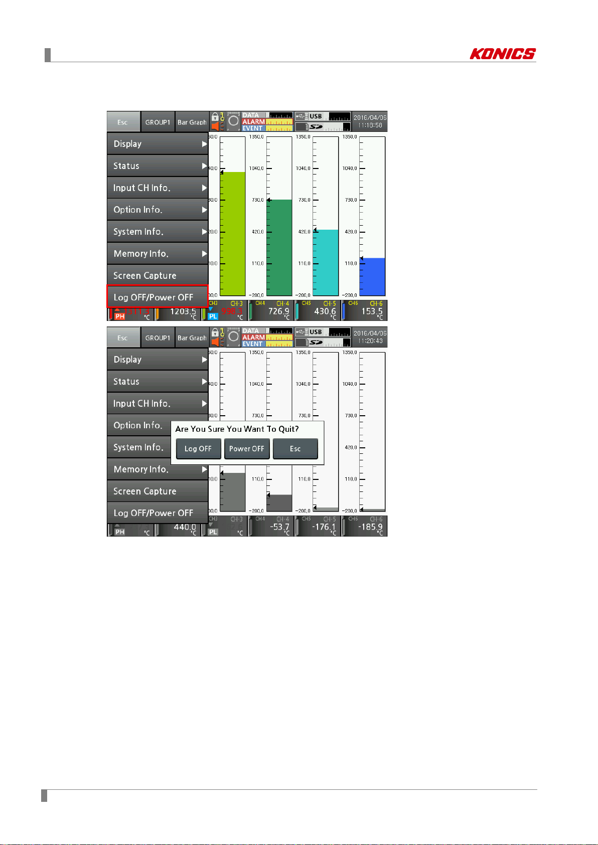
7 Menu
7.8 Log OFF/Power OFF
It tu
rns log off, power off of KRN1000.
Log OFF: Logs OFF the administer mode, and changes standard user mode.
In case of standard user mode, it does not activated.
Power OFF: Turns OFF the power.
76 © Copyright Reserved KONICS Co., Ltd.

8 Integrated device management program (DAQMaster)
8 Integrated device management program
(DAQMaster)
8.1 Overview
DAQMaster is the comprehensive device management program and is able to utilize for
temperature controller product line, meter product line, counter product line and recorder product
line, etc.
DAQMaster provides graph user interface (GUI) for easy and convenient integrated several
products’ parameter setting and data monitoring.
Visit our homepage (www.konics.com) to download ‘DAQMaster user manual’.
This ‘KRN1000 user manual’ describes only for dedicated KRN1000 functions. For more
information about DAQMaster, please refer to ‘DAQMaster user manual’.
© Copyright Reserved KONICS Co., Ltd. 77

8 Integrated device management program (DAQMaster)
8.2 Features
DAQMaster has the following features.
Supports multiple device
DAQMaster is able to simultaneously monitor multiple devices and set parameters of the
devices. The units with different addresses in a single device are connectable at the same
time. In Modbus RTU communication, several RS232 port are available.
Device scan
In case multiple units (with different addresses) are connected together, use unit scan
function to automatically search for units.
Convenient user interface
User can arrange windows, attributes, and project screens, etc to monitor the data as
convenient. When saving the project, set screen is also saved.
Project management
You can save the setting of monitoring for added device and data, selection of I/O source,
etc as the project. When loading the project, this file has the saved setting status. You can
also construct project list for convenient project file management.
Monitoring data log
It logs the data during monitoring and is able to save it as one of DAQMaster data file (*.ddf)
or CSV file (*.csv). You can load the saved CSV file in Microsoft Excel directly. You can
also designate file name, storage rules, and storage folders for easy file management.
Data analysis
You can analyze data file (*.ddf) with DAQMaster’s data analysis function as spread or
graph. You can save the analysis as *.rtf, *.txt, *.html, or *.csv file on spread.
Modbus map table reporting output
It can output the registered Modbus device address map as report. You can save the report
for Modbus map table as HTML file (*.html) or PDF file (*.pdf).
Supports multi-language
It supports Korean, English, Japanese and Simplified Chinese. To add a different language,
modify the files in the Lang folder, rename, and save it.
Supports script
You can designate each other different I/O process by device using Lua scr ipt language.
78 © Copyright Reserved KONICS Co., Ltd.

8 Integrated device management program (DAQMaster)
8.3 Dedicated featu res for KRN1000
Among DAQMaster’s functions, there are dedicated KRN1000 functions during communicating
with DAQMaster.
© Copyright Reserved KONICS Co., Ltd. 79

8 Integrated device management program (DAQMaster)
8.3.1 Record Backup
You can download backup data which is saved in KRN1000 internal memory from “Record
Backup” section.
Directory form is year, month, day. Click the relevant icon and check below list.
To download backup file, click the file name with right mouse button and select "Download Log
File" menu.
Backup files are strucured as tree type directory at KRN1000 internal memory. You can easily
fine and download the desired file.
80 © Copyright Reserved KONICS Co., Ltd.

8 Integrated device management program (DAQMaster)
8.3.2 Check backup data
This function is output downloaded backup data by DAQMater or an USB memory.
1st Execute Data Analysis. At taskbar, click [Start]-[Program]-[DAQMaster]-[Data
Analysis] or at DAQMaster menu, click [Tool]-[Data Analysis].
2nd ‘Data Analaysis’ program opens. Click open file icon and select downloaded ".KRD"
file.
© Copyright Reserved KONICS Co., Ltd. 81

8 Integrated device management program (DAQMaster)
3rd Open chart and drag the desired channel to check waveforms or values.
For more information, please refer to ‘DAQMaster user manual’.
82 © Copyright Reserved KONICS Co., Ltd.

9 Troubleshooting
When power ON, KRN1000 does not
operate.
KRN1000 has date and time error within
Set date and time again.
Check sensor input settings are correct in input
type setting.
When power ON, after booting screen,
operation screen.
USB memory’s file system supports only FAT1 6
Format as FAT16 or FAT32.
If partitions of an USB memory are divided,
KRN1000 recognizes only first partition.
Communication connection via ethernet
communication does not execute.
Check communication line connection and reset
it as following ‘7.4.4 Ethernet/USB’.
Check signal polarity connection of RX+, RX-,
Reset it as following ‘7.4.3 RS422/485’.
Re-calibrate touch as following ‘7.1.4
‘7.1.3 Touch Calibration’.
In case of current, connect shunt resistance.
following '2.2 Input/Output'.
9 Troubleshooting
Check KRN1000 normal operation regularly.
No Error Troubleshooting
1
display anything on LCD screen and
2 Displayed date and time is not correct.
3 Sensor input value is not right.
4
KRN1000 does not change normal
5 SD/USB memory is not recognized.
6
Communication connection via RS422/485
7
communication does not execute.
8 Screen touch position is not correct.
Check power supply and power connector is
connected normally.
±2min/year (Useable until in 2099).
Internal memory of KRN1000 may have error.
Contact KONICS service center or seller.
and FAT32.
TX+, TX- communication line.
Touch Calibration’.
When touch calibration is wrong, reset the
setting and re-calibrate touch as following
9 Current measurement is not correct.
Measure shunt resistance connection method as
© Copyright Reserved KONICS Co., Ltd. 83

9 Troubleshooting
Error
message
9.1 Error message
Displays error messages on screen and print data when error occurs.
Descriptions
When input type is temperature sensor (Thermocouple, RTD) and the
measurement value is higher than high-limit value of input range, it flashes
HHHH. It is cleared when the measurement value is within the high-limit range.
HHHH
LLLL
BURN
When input type is analog (voltage, current (shunt)) and the measurement value
is over 10% of high-limit input range, it flashes HHHH. It is cleared when the
measurement value is within 10% of high-limit input range.
When input type is temperature sensor (Thermocouple, RTD) and the
measurement value is lower than low-limit value of input range, it flashes LLLL. It
is cleared when the measurement value is within the low-limit range.
When input type is analog (voltage, current (shunt)) and the measurement value
is over 10% of low-limit input range, it flashes LLLL. It is cleared when the
measurement value is within 10% of low-limit input range.
When input type is temperature sensor (Thermocouple, RTD) and input is break,
it flashes BURN. It is cleared when input is connected.
Refer to Burn-out Action of ‘7.3.2 Input Option’.
When forgetting and entering unvaild password 3 times, “ASKey” appears with
error message. Contact our service center with ASKey.
ASKey
84 © Copyright Reserved KONICS Co., Ltd.

9 Troubleshooting
© Copyright Reserved KONICS Co., Ltd. 85

9 Troubleshooting
86 © Copyright Reserved KONICS Co., Ltd.
KUM-E-0180C_20160923
 Loading...