

Konica Minolta ViZion DR+ 1417V2 Dealers Installation Manual

1
ViZion DR+
1417V2
Wireless
Panel
Dealer
Installation
Manual

[ViZion DR+ 1417V2 Wireless Panel Installation Manual]
[Ultra 4.2.9.0]
2
Customer Support
1.800.366.5343 –
HCITsupport@konicaminolta.com
Table of Contents
Revision History ......................................................................................................................... 3
Introduction ................................................................................................................................ 4
Hardware Overview and Installation ........................................................................................... 5
1 ViZion DR+ 1417V2 Wireless Panel Hardware ................................................................... 5
1.1 Passive Installation ...................................................................................................... 5
1.2 Integrated Installation ................................................................................................... 5
1.3 ViZion DR+ 1417V2 Wireless Panel Detector (Mars1417V2) ....................................... 6
1.4 G.I.P.S. Box (Generator Integration Power Supply) ..................................................... 7
1.5 Synchronization, Ethernet and Power Cables .............................................................. 7
1.6 ViZion DR+ Wireless Panel Battery Charger ................................................................ 8
1.7 Additional Components ................................................................................................ 9
2 Hardware Installation .......................................................................................................... 9
2.1 Fixed Room Hardware Installation ............................................................................... 9
2.2 Mobile Hardware Installation .......................................................................................10
3 Network Installation ............................................................................................................11
3.1 Fixed Room Network Configuration ............................................................................11
3.2 Mobile Network Configuration .....................................................................................12
Software Installation and Configuration .....................................................................................15
4 Software Installation ...........................................................................................................15
4.1 Install Microsoft Visual C++ Redistributable ................................................................15
4.2 Installation of Ultra Software ................................................................ .......................16
4.3 Configuration of Ultra Software ...................................................................................16
4.4 Device Licensing .........................................................................................................18
4.5 Device Driver Installation ............................................................................................18
4.6 Device Pool Configuration ...........................................................................................21
4.7 iDetector Interface.......................................................................................................22

[ViZion DR+ 1417V2 Wireless Panel Installation Manual]
[Ultra 4.2.9.0]
3
Customer Support
1.800.366.5343 –
HCITsupport@konicaminolta.com
Revision History
REV DATE DOCUMENT NAME [REASON FOR CHANGE]
1.0 6/27/2018 ViZion DR+ 1417V2 Wireless Panel Installation Manual
[New Manual – iRay SDK Version 2 and Ultra version 4.2.9.0]
Distributed by:
Konica Minolta Healthcare Americas, Inc.
2217 US Highway 70 East
Garner, NC 27529
1-800-366-5343
4
Customer Support
1.800.366.5343 –
HCITsupport@konicaminolta.com
Introduction
This documentation is provided to you, the service technician, with all information necessary to install,
configure and calibrate the ViZion DR+ 1417V2 Wireless Panel. For more detailed information on the
operation and specifications of your wireless detector, please review the following documentation:
Manual References:
• 059-201-04 Mars1417V2 User Manual A0.pdf
Only qualified service personnel should attempt
to install, modify, service or operate the ViZion
DR+ Wireless Panel detector.
5
Customer Support
1.800.366.5343 –
HCITsupport@konicaminolta.com
Hardware Overview and Installation
1 ViZion DR+ 1417V2 Wireless
Panel Hardware
The following equipment is required to properly
install and implement your ViZion DR+ system.
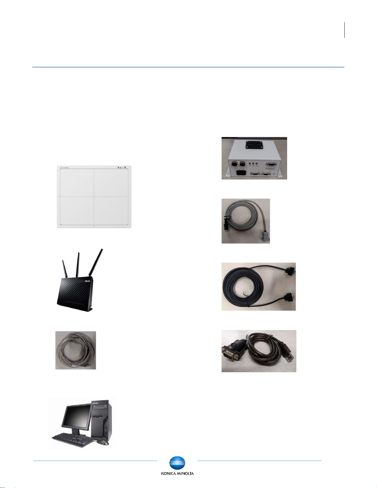
1.1 Passive Installation
• ViZion DR+ 1417V2 Wireless Panel
Detector
• ASUS Dual-Band Wi-Fi Gigabit AP
• 75 ft. Cat5 Ethernet Cable
• Acquisition PC Desktop or Laptop
(Windows 10)
1.2 Integrated Installation
The following additional equipment is required
for integration with a generator.
• G.I.P.S. Box
• Power Supply Synchronization Cable
• 50 ft. Female-to-Female Serial Cable
• Tripp Lite USB-to-Serial Adapter
[ViZion DR+ 1417V2 Wireless Panel Installation Manual]
[Ultra 4.2.9.0]
6
Customer Support
1.800.366.5343 –
HCITsupport@konicaminolta.com
1.3 ViZion DR+ 1417V2 Wireless
Panel Detector (Mars1417V2)
The following equipment is required for
integration with a generator.
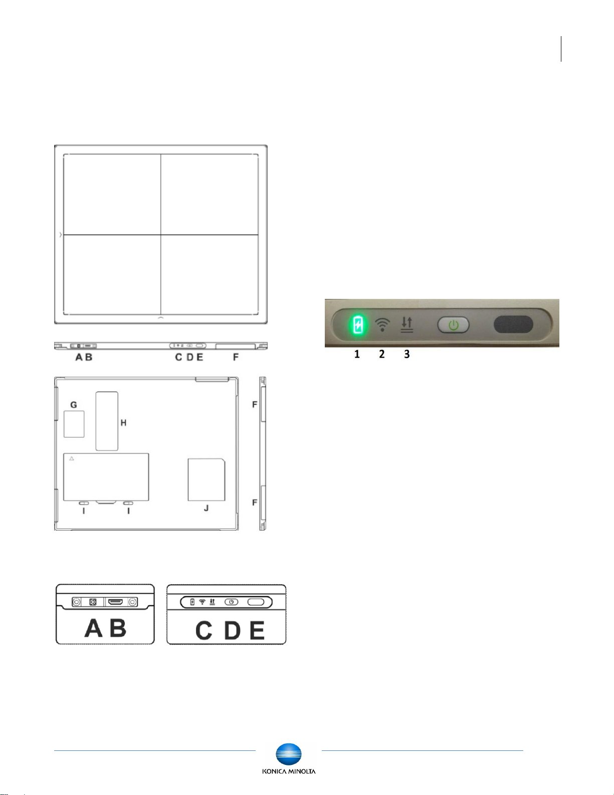
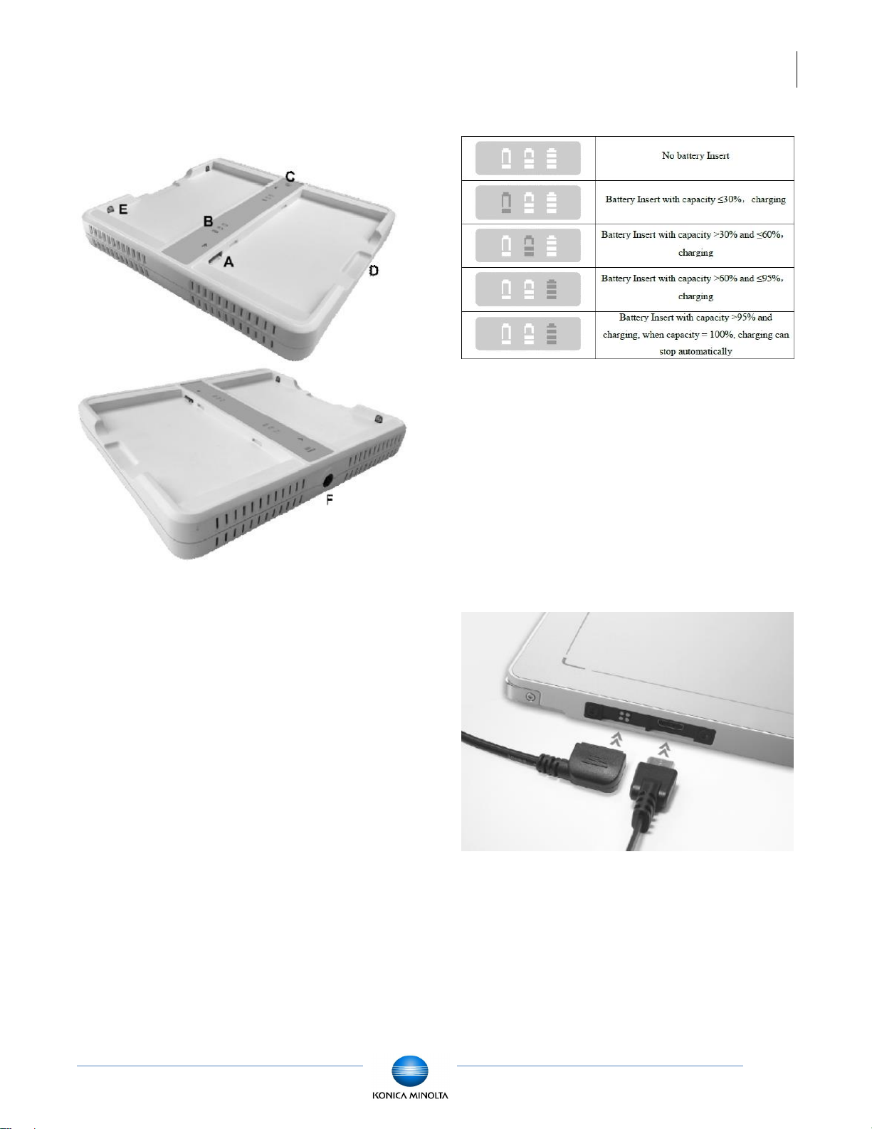
1.3.1 Connector Ports and Control Panel
A. DC Jack: 24V DC input
B. Ethernet interface: Link cable jack
C. LED indicators: Indicates the state of the
detector
D. Power button: Detector power ON/OFF
button
E. Infrared window: Infrared device sensor
F. Antenna: Wi-Fi antennas (three)
G. Reserved
H. Maintenance cover: For service engineer to
maintenance
I. Battery lock: The lock button for detaching
battery
J. Detector label: Serial number and product
information
1.3.2 LED Indicators
1. Battery Indicator:
• Green: battery charge is < 10%
• Orange: battery charge is ≥ 10%
2. Link Indicator:
• Blue (solid): wireless connection is
connected
• Blue (blinking): wireless connection is
ready, but not connected
• Green (solid): wired connection is
connected
• Green (blinking): panel initialization
3. Status Indicator:
• Green (solid): data transmission
• Orange (solid): panel initialization
• Orange (blinking): fatal error
[ViZion DR+ 1417V2 Wireless Panel Installation Manual]
[Ultra 4.2.9.0]
7
Customer Support
1.800.366.5343 –
HCITsupport@konicaminolta.com
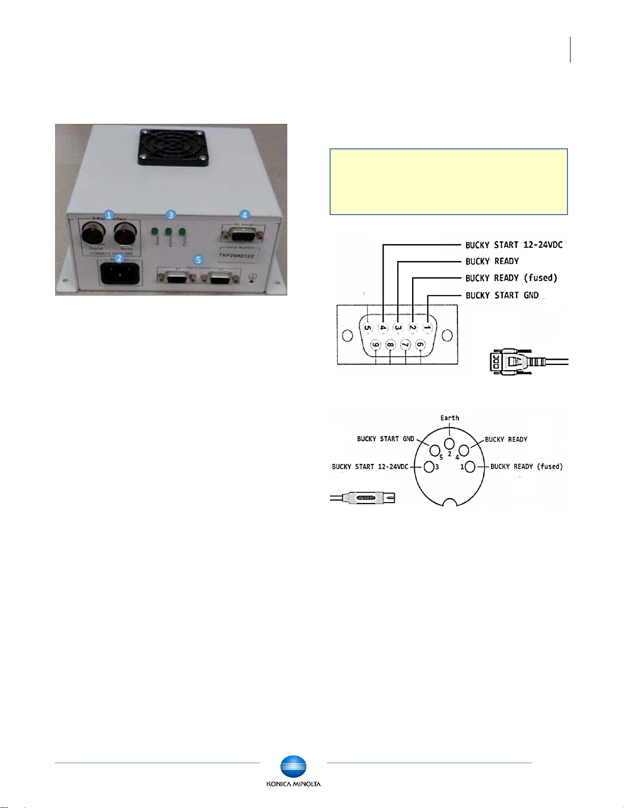
1.4 G.I.P.S. Box (Generator
Integration Power Supply)
1. X-Ray Interface (connect only one)
• 12-24 VDC Digital
• 120 VAC Bucky
2. AC Power port (Three-Prong)
3. LED Lights (Power / System / Status)
4. Computer Serial port (male)
5. Panel Power (Panel 1 and Panel 2)
1.5 Synchronization, Ethernet and
Power Cables
Your ViZion DR+ wireless detector includes the
following accessories:
• 75 ft. Cat5 Ethernet Cable
• 50 ft. Female-to-Female Serial Cable
• Tripp Lite USB-to-Serial Adapter
• Power Supply Synchronization Cable
1.5.1 Synchronization Cable
Review the available signal wires in the
following figures prior to connecting the
generator synchronization cable.
Note: depending on generator setup, you
may need to cut off the DB9 end
and wire directly.
[ViZion DR+ 1417V2 Wireless Panel Installation Manual]
[Ultra 4.2.9.0]
8
Customer Support
1.800.366.5343 –
HCITsupport@konicaminolta.com
1.6 ViZion DR+ Wireless Panel
Battery Charger
A. Battery interface: 8-pin battery connector
B. Capacity indicator: Charged capacity
percentage of inserted battery from ≤ 30%
up to 100% (Figure 9)
C. Power indicator: Green light displays when
power is on
D. Hand pull position
E. Limit ball plug
F. DC Jack (24V DC input)
1.6.1 Battery Charger Capacity Indicators
1.6.2 Connector Ports
It is alternatively possible to trickle charge the
battery inside the panel, by connecting the DC
power cable from the DC medical adapter
power supply to the DC input of the detector.
To preconfigure the panel for alternate wireless
connection modes and panel calibration,
connect the Link cable to the mini-HDMI
ethernet interface of the detector for a wired
network connection.
[ViZion DR+ 1417V2 Wireless Panel Installation Manual]
[Ultra 4.2.9.0]
9
Customer Support
1.800.366.5343 –
HCITsupport@konicaminolta.com
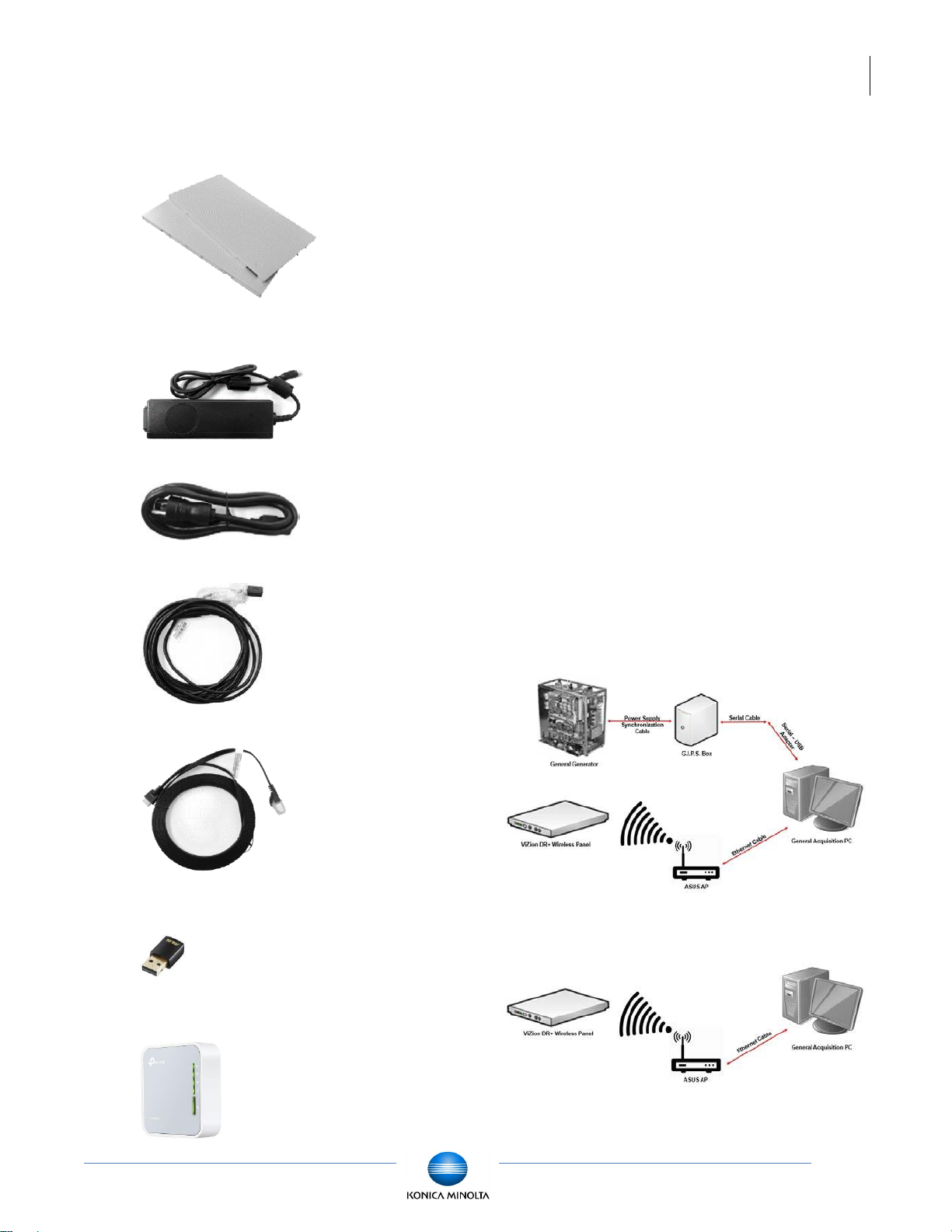
1.7 Additional Components
• Battery Pack (2)
• DC Medical Adapter for Detector and
Battery Charger
• AC Power Cable
• DC Power Cable
• Link Cable
• ASUS Dual-Band Wireless USB Adapter
(option for mobile)
• TP-Link AC750 Wireless Travel Router
Access Point (option for mobile)
2 Hardware Installation
Now that you have verified the hardware, the
next step is to connect all of the devices
together. If you are uncertain whether or not
you have all required hardware, please consult
the equipment list, which can be located at the
beginning of Section 1.
The following sections provide step-by-step
instructions to complete the hardware
installation. The connections between the
various devices are more or less
straightforward; however, only a qualified
service technician should attempt to connect
the synchronization cable to the generator and
bucky interface.
The following diagrams illustrate the completed
hardware installation. Note that this diagram
does not take into account any connection to a
corporate LAN.
2.1 Fixed Room Hardware
Installation
The following diagram is an example of an
Integrated hardware installation:
The following diagram is an example of a
Passive hardware installation:
[ViZion DR+ 1417V2 Wireless Panel Installation Manual]
[Ultra 4.2.9.0]
10
Customer Support
1.800.366.5343 –
HCITsupport@konicaminolta.com
2.1.1 Connecting the Synchronization Cable
The power supply generator synchronization
cable enables communication between the
ViZion DR+ wireless detector and the X-ray
generator to take place. One end of this cable
connects directly to the G.I.P.S. box. The other
end of the cable connects to the X-ray
generator. Depending on the manufacturer and
model of your X-ray generator, your
synchronization cable may need to be retrofitted with the appropriate adapter.
Connect the power supply synchronization
cable.
1. Connect power supply synchronization
cable to Port 1 (either A or B depending
on the expected voltage signal) on the
G.I.P.S. box.
2. Connect the other end of the
synchronization cable to your
Generator (remote triggering device or
bucky interface).
Note: You can find detailed information
on connecting your cable to a
specific generator in the appropriate
appendix in the Engineering folder
located on the desktop of the Ultra
workstation.
2.1.2 Connecting the G.I.P.S Box to the
Acquisition PC
To connect the G.I.P.S. box to the acquisition
PC for integration:
1. Connect the 50’ F-to-F serial cable to
Port 4 on the G.I.P.S. box.
2. Connect the other end of the 50’ serial
cable to the serial-to-USB adapter.
3. Plug the USB adapter end into one of
the USB ports on the back of the
acquisition PC.
2.1.3 Connecting the Acquisition PC to the
Wireless Access Point
To connect the ASUS AP to the acquisition PC:
1. Connect the 75’ Cat5 ethernet cable to
one of the Yellow Ports on the back of
the ASUS AP.
2. Connect the other end of the ethernet
cable to the Intel Gigabit CT Network
Adapter on the acquisition PC.
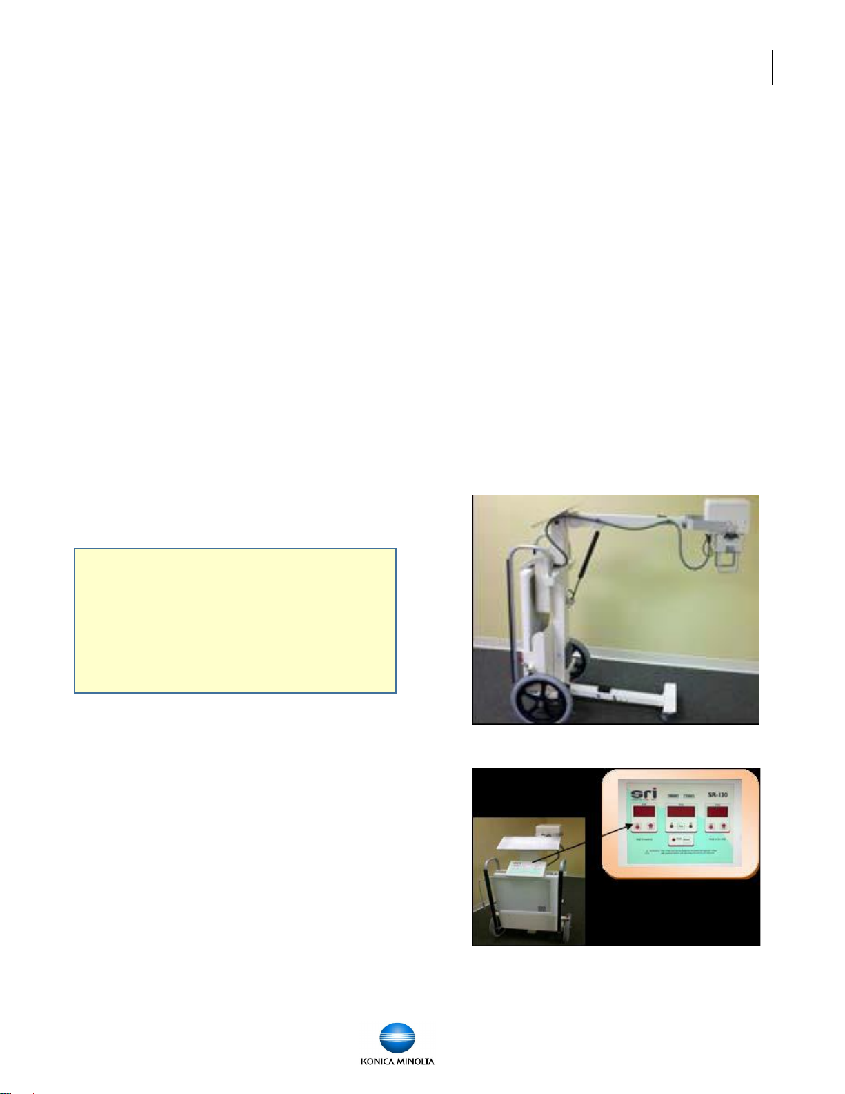
2.2 Mobile Hardware Installation
Begin by taking an inventory of the additional
required equipment, which can be found at the
end of Section 1.
2.2.1 SourceRay SR-130 Mobile X-Ray Unit
• Side view
• Console view
 Loading...