

Page 1
Page 2

Page 3

Introduction
Welcome
The Konica IP-413 is a print controller designed to be a built-in type server for
the Konica 7115/7118/7115F/7118F printer/copier. It enables direct printing
from Windows-compliant computers. It can also enable use of the copier as a
network printer when an optional network interface card is used.
About this Manual
This manual is used only for the IP-413 Print Controller.
This manual describes how to operate the IP-413 Print Controller and Printer
Driver when the Konica 7115/7118/7115F/7118F is used as a printer by
connecting it to computers.
This manual assumes you are familiar with the basic operation of Windows and
Copier.
The copier and the network management utility Light are separately supplied
with Instruction manuals. Refer to these manuals as needed.
For detailed operations of Windows 95/98/Me and Windows NT4.0/2000, refer
to the operating manuals for each operating system. For application operations,
refer to the operating manuals provided with each application.
COPYRIGHT:
© 2002 Konica Corporation.
ACKNOWLEDGEMENTS:
Ethernet is a registered trademark of Xerox Corporation.
Microsoft, MS, MS-DOS, Windows, and Windows NT are registered
trademarks of Microsoft Corporation.
Netscape Communications, the Netscape Communications logo, Netscape
Navigator, Netscape Communicator, and Netscape are trademarks of Netscape
Communications Corporation.
Novell and NetWare are registered trademarks of Novell, Inc.
HP and PCL are registered trademarks of Hewlett-Packard Company Limited.
Novell and NetWare are registered trademarks of U.S. Novell, Inc.
All other product names are trademarks or registered trademarks of their
respective holders.
i
Page 4

NOTICE:
Konica Corporation has made every effort to ensure that the information in this
manual is complete and accurate. However, constant efforts are also being made
to improve and update the product.
Therefore, Konica Corporation shall not be liable for errors in this manual or for
any consequential damages resulting from the use of this manual.
Screen images shown in this manual may differ slightly from actual ones. In
addition, the explanations are given using Internet Explorer as the Web browser.
The information contained herein is subject to change without notice.
FEDERAL OR STATE STATUTES MAY PROHIBIT THE COPYING OF
CERTAIN DOCUMENTS OR INFORMATION, RESULTING IN FINES OR
IMPRISONMENT FOR VIOLATORS.
MANUAL PART NUMBER:
OP-IP413-01
Conventions Used in This Manual
The following terminology is used throughout this manual:
1. IP-413 Print controller is a Print Controller
2. A Printer, an IP-Engine or an Engine is a Digital Copier
3. KN-305 optional Network Interface Card is a network interface card
( or NIC)
4. A printing system that combines the products listed in items1, 2 and 3
above is a printing system.
5. Windows 98 is Microsoft Windows 98
Windows Me is Microsoft Windows Me
Windows NT4.0 or Windows NT is Microsoft Windows NT4.0
Windows 2000 is Microsoft Windows 2000
6. When referencing multiple Microsoft OSs, they will appear as follows:
Windows 95/98/Me
Windows NT4.0/2000
Windows NT/2000
Windows 95/98/Me/NT/2000
ii
Page 5

For the U.S.A. Users
FCC Part 15-Radio Frequency Devices
This device complies with Part 15 of the FCC Rules. Operation is subject to the
following two conditions: (1) This device may not cause harmful interference, and
(2) this device must accept any interface received, including interface that may
cause undesired operation.
NOTE: This equipment has been tested and found to comply with the limits for a
Class A digital device, pursuant to Part 15 of the FCC Rules. These limits are
designed to provide reasonable protection against harmful interference when the
equipment is operated in a commercial environment. This equipment generates,
uses, and can radiate radio frequency energy and if not installed and used in
accordance with the instruction manual, may cause harmful interference to radio
communications.
Operation of this equipment in a residential area is likely to cause harmful interference in which case the user will be required to correct the interference at his
own expense.
WARNING: The design and production of this unit conform to FCC Regulations,
and any changes or modifications must be registered with the FCC and are subject to FCC control. Any changes made by purchaser or user without first contacting the manufacturer will be subject to penalty under FCC regulations.
This device must be used with shielded interface cables. The use of nonshielded cables is likely to result in interference with radio communications and is
prohibited under FCC rules.
For Canada Users
Interference-Causing Equipment Standard (ICES-003 Issue 3)
This Class A digital apparatus complies with Canadian ICES-003.
Cet appareil numerique de la classe A est conforme a la norme NMB-003 du
Canada.
iii
Page 6
For Europe
CE Marking (Declaration of Conformity)
This product complies with the following EU directives:
89/336/EEC, 73/23/EEC and 93/68/EEC directives.
This declaration is valid for the area of the European Union.
This device must be used with shielded interface cables. The use of nonshielded cables is likely to result in interference with radio communications and is
prohibited under EU directives.
For Users of the Class B regulation’s countries
This device must be used with shielded interface cables. The use of nonshielded cables is likely to result in interference with radio communications and is
prohibited under CISPR 22 rules and local rules.
For Users except the Class B regulation’s countries
WARNING
This is a Class A product. In a domestic environment this product may cause
radio interference in which case the user may be required to take adequate measures.
This device must be used with shielded interface cables. The use of nonshielded cables is likely to result in interference with radio communications and is
prohibited under CISPR 22 rules and local rules.
iv
Page 7

Contents
CONTENTS
1 Getting Started .................................................. 1
1.1 System Requirements ............................................. 1
2 Connecting to a Computer ............................... 2
2.1 Connecting to the Parallel Port
(Local Connection) .................................................. 3
2.2 Connecting to the Ethernet 10/100Base-T
Port (Network Connection) ..................................... 4
3 Installing the Printer Driver .............................. 5
3.1 Windows 95/98/Me ................................................... 5
3.2 Windows NT 4.0 ....................................................... 7
3.3 Windows 2000 ........................................................ 10
3.4 Uninstalling the Printer Driver .............................. 13
4 Printer Driver Settings .................................... 14
4.1 Displaying the Printer Driver Setup Dialog ......... 14
4.2 Common Settings .................................................. 15
4.3 Setup Tab ................................................................ 16
4.3.1 N-up ...................................................................... 17
4.3.2 Watermark ............................................................ 18
4.3.3 Paper Source ....................................................... 20
4.4 Paper Tab ................................................................ 21
4.4.1 Original Document Size ...................................... 21
4.4.2 Output Paper Size ............................................... 23
v
Page 8

Contents
4.4.3 Copies .................................................................. 24
4.4.4 Collate at Printer ................................................. 24
4.4.5 Orientation ........................................................... 24
4.5 Quality ..................................................................... 25
4.5.1 Resolution ........................................................... 25
4.5.2 Toner Save ........................................................... 25
4.5.3 Rendering Mode .................................................. 25
4.5.4 Font Setting ......................................................... 26
4.5.5 Image Adjustment ............................................... 26
4.6 Device Option Tab .................................................. 27
5 Digital Copier Control Panel Operations
(PC Print Mode) ............................................... 28
5.1 Operation Using the 7115/7118 ............................ 28
5.1.1 Names of Control Panel Parts and
Their Functions ................................................... 29
5.1.2 [PRINT] Indicator/[START] Key .......................... 30
5.1.3 Cancelling a Print Job ........................................ 30
5.1.4 Using Manual Bypass Tray ................................. 31
5.1.5 Outputting a Report ............................................ 32
5.2 Operation Using the 7115F/7118F ........................ 34
5.2.1 Names of Control Panel Parts and
Their Functions ................................................... 35
5.2.2 [PRINT] Indicator/[START] Key .......................... 36
5.2.3 Switching to PC Print Mode ............................... 36
5.2.4 Cancelling a Print Job ........................................ 37
5.2.5 Using Manual Bypass Tray ................................. 38
5.2.6 Outputting a Report ............................................ 40
vi
Page 9

6 Digital Copier Settings for Use
on a Network .................................................... 41
6.1 Specifying Settings Using the 7115/7118 ............ 42
6.1.1 IP Address ........................................................... 42
6.1.2 Entering Values ................................................... 43
6.1.3 Subnet Mask ........................................................ 44
6.1.4 Gateway ............................................................... 44
6.1.5 Restarting the Digital Copier ............................. 45
6.2 Specifying Settings Using the 7115F/7118F ........ 46
6.2.1 IP Address ........................................................... 46
6.2.2 Subnet Mask ........................................................ 47
6.2.3 Default Gateway .................................................. 48
6.2.4 Restarting the Digital Copier ............................. 48
7 Network Printing in a Windows
Environment ..................................................... 49
Contents
7.1 Peer-to-Peer Printing (Windows 95/98/Me) .......... 49
7.1.1 Before You Begin ................................................ 49
7.1.2 Settings for Windows 95/98/Me ......................... 49
7.2 LPR Printing (Windows NT 4.0/2000) ................... 51
7.2.1 Before You Begin ................................................ 51
7.2.2 Settings for Windows NT 4.0 .............................. 51
7.2.3 Settings for Windows 2000 ................................ 52
7.3 IPP Printing (Windows 2000) ................................ 54
7.3.1 Before You Begin ................................................ 54
7.3.2 Installing the Printer Driver ................................ 54
7.4 Printing via a NetWare Server ............................... 55
7.4.1 Before You Begin ................................................ 55
7.4.2 Settings for Windows 95/98/Me ......................... 56
7.4.3 Settings for Windows NT 4.0/2000 ..................... 57
vii
Page 10

Contents
8 Troubleshooting ............................................... 58
8.1 Correcting Errors for the 7115/7118 ..................... 58
8.1.1 Main Error Messages .......................................... 58
8.2 Correcting Errors for the 7115F/7118F ................ 60
8.2.1 Checking Error Messages .................................. 60
8.2.2 Main Error Messages .......................................... 61
9 Appendix .......................................................... 62
9.1 Assigning IP Parameters Using Initializer ........... 62
9.1.1 Using Initializer ................................................... 62
9.2 Specifications ........................................................ 64
9.3 IP-413 Printer Configuration Page ........................ 65
9.4 IP-413 PCL Font List .............................................. 66
viii
Page 11

1 Getting Started
1 Getting Started
1.1 System Requirements
Operating System
• Microsoft Windows 95
• Microsoft Windows 98
• Microsoft Windows Me
• Microsoft Windows NT 4.0
• Microsoft Windows 2000
When the network interface card is installed, the print controller will run in
the following environments.
Client operating systems Windows 95/98/Me/NT 4.0/2000
Network interface type Ethernet 10/100Base-T
Network protocol TCP/IP, IPX/SPX
1
Page 12

2 Connecting to a Computer
2 Connecting to a Computer
Connect the print controller to the computer using either of the following
two methods.
To connect to the parallel port
Using a parallel cable, locally connect the printer directly to a
computer.
Refer to “2.1 Connecting to the Parallel Port (Local Connection)” on
page 3.
To connect to the Ethernet 10/100Base-T port
If the printer is to be used on a network, connect it using a 10/100BaseT cable.
Refer to “2.2 Connecting to the Ethernet 10/100Base-T Port (Network
Connection)” on page 4.
Important!
• If the printer is to be used on a network, the optional network
interface card KN-305 must be installed.
2
Page 13
2 Connecting to a Computer
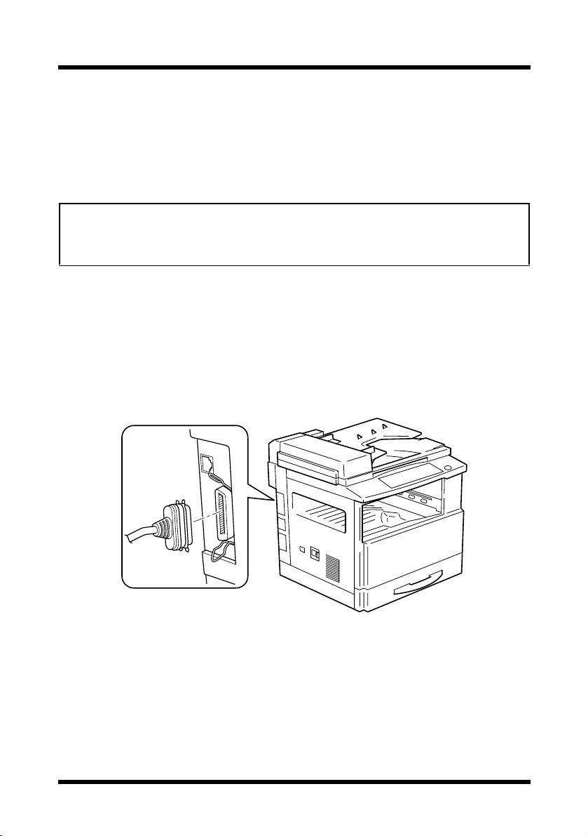
2.1 Connecting to the Parallel Port (Local Connection)
Use the parallel cable to connect the parallel port of the print controller to
the parallel port of the computer.
Important!
• Be sure to use a shielded parallel cable. Use of an unshielded cable
may result in radio frequency interference.
• The parallel port is compatible with IEEE1284 Type B standards.
1. Make sure that the Digital Copier and the computer to be connected to
the Digital Copier are both turned OFF.
2. Connect one end of the parallel cable to the parallel port (printer port)
of the computer.
3. Connect the other end of the cable to the parallel port of the print controller installed in the Digital Copier.
This completes the connection of the print controller to the computer.
3
Page 14
2 Connecting to a Computer
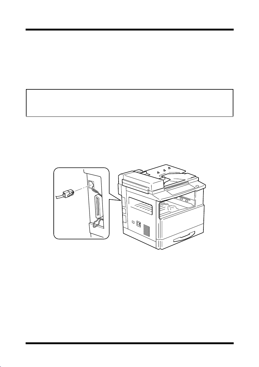
2.2 Connecting to the Ethernet 10/100Base-T Port
(Network Connection)
If the printer is to be used on a network, connect the network interface card
to the network (LAN).
Important!
• This connection requires the optional network interface card KN-305.
• Be sure to use a shielded cable for the Ethernet 10/100Base-T cable.
Use of an unshielded cable may result in radio frequency interference.
1. Make sure that the Digital Copier is turned OFF.
2. Connect one end of the Ethernet 10/100Base-T cable to the 10/
100Base-T port of the network interface card, and then connect the
other end of the cable to the hub.
This completes the network connection.
4
Page 15
3 Installing the Printer Driver
3 Installing the Printer Driver
This section explains the procedure for installing the printer driver in the
CD-ROM that comes with the print controller.
The installation procedure differs according to the computer’s operating
system. See the page indicated below for the installation procedure
corresponding to your computer’s operating system.
•“3.1 Windows 95/98/Me” on page 5
•“3.2 Windows NT 4.0” on page 7
•“3.3 Windows 2000” on page 10
3.1 Windows 95/98/Me
1. Turn on the Digital Copier.
2. Turn on your computer and start up Windows 95, 98 or Me.
3. Insert the accompanying CD-ROM that comes with your print controller into your computer’s CD-ROM drive.
[Start]
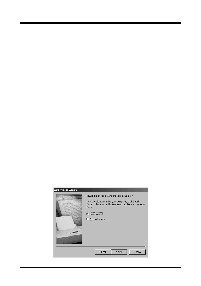
4. Click the
5. Double-click the “
6. Click the
7. Select “
Local printer
button, point to
[Next]
button.
Add Printer
”.
[Settings]
” icon.
, and then click
[Printers]
.
5
Page 16

3 Installing the Printer Driver
Note
• For details on specifying network settings, refer to “7 Network
Printing in a Windows Environment” on page 49. Since other
network settings must first be specified, temporarily install the
printer driver under a local connection.
• For the network printer settings, consult with the network
administrator.
8. Click the
9. Click the
10. Click the
[Next]
button.
[Have Disk]
[Browse]
button.
button.
11. Specify the printer driver directory on the CD-ROM for the environment being used, and then click the
[OK]
button. (Example: CD-ROM
drive\English\Win 98\PCL6\)
Then click the
12. Click the
[OK]
[OK]
button.
button.
13. Select the model of the Digital Copier you use.
[Next]
14. Click the
button.
15. Specify the port (LPT1, 2, etc.) where the print controller is connected.
[Next]
16. Click the
17. Specify the printer name and click the
Default: “
18. Click the
button.
Konica 7118 PCL6
[Finish]
button.
[Next]
Konica 7115 PCL6
” or “
button.
”
6
Page 17
3 Installing the Printer Driver
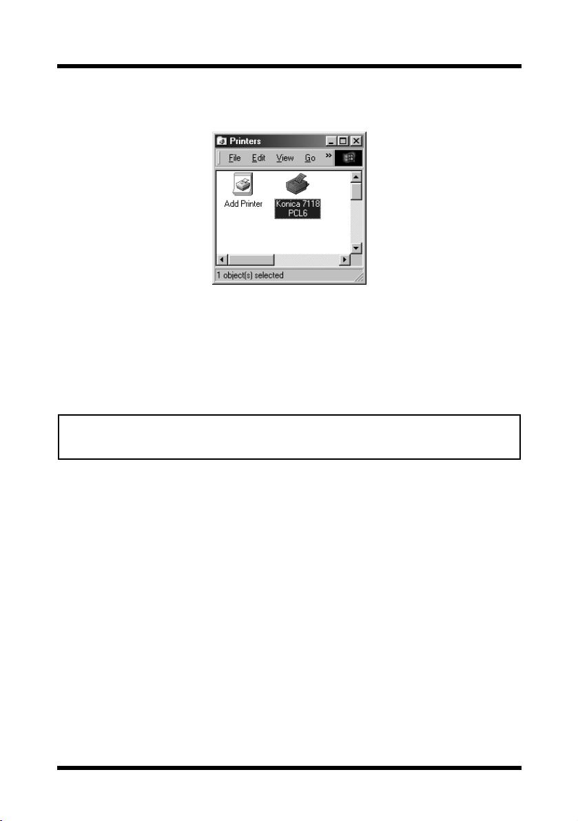
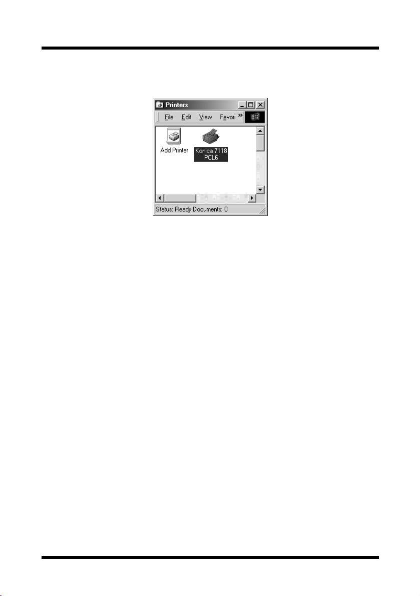
19. After installation is complete, check that the icon for the installed
printer appears in the “
Printers
” window.
20. Eject the CD-ROM from your computer’s CD-ROM drive.
This completes the installation of the printer driver.
3.2 Windows NT 4.0
Note
• When installing the printer driver on Windows NT 4.0, be sure to log in
with Power User or higher-level privileges.
1. Turn on the Digital Copier.
2. Turn on your computer and start up Windows NT 4.0.
3. Insert the accompanying CD-ROM that comes with your print controller into your computer’s CD-ROM drive.
[Start]
4. Click the
button, point to
5. Double-click the “
Add Printer
[Settings]
” icon.
, and then click
[Printers]
.
7
Page 18
3 Installing the Printer Driver
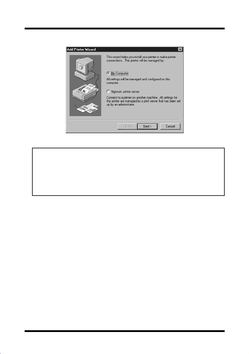
6. Select “
My Computer
” and click the
[Next]
button.
Note
• For details on specifying network settings, refer to “7 Network
Printing in a Windows Environment” on page 49. Since other
network settings must first be specified, temporarily install the
printer driver under a local connection.
• For the network printer settings, consult with the network
administrator.
7. Specify the port (LPT1, 2, etc.) where the print controller is connected.
[Next]
8. Click the
9. Click the
10. Click the
button.
[Have Disk]
[Browse]
button.
button.
11. Specify the printer driver directory on the CD-ROM for the environ-
[OK]
ment being used, and then click the
button. (Example: CD-ROM
drive\English\Win NT\PCL6\)
Then click the
12. Click the
[OK]
[Open]
button.
button.
13. Select the model of the copier you use.
[Next]
14. Click the
button.
8
Page 19
3 Installing the Printer Driver
15. Specify the printer name and click the
Default: “
Konica 7118 PCL6
” or “
16. If you want the Digital Copier to be the default printer select
if not, select
17. Click the
18. Select “
If you choose “
19. Click the
[No]
.
[Next]
button.
Not shared
Shared
[Next]
button.
Shared
” or “
”, specify the share name of the printer.
[Next]
button.
Konica 7115 PCL6
” by clicking.
”
[Yes]
20. Select whether you will print the print test or not.
[Yes]
Select
21. Click the
to print the test page, or select
[Finish]
button.
[No]
not to perform it.
22. After installation is complete, check that the icon for the installed
printer appears in the “
Printers
” window.
;
23. Eject the CD-ROM from your computer’s CD-ROM drive.
This completes the installation of the printer driver.
9
Page 20
3 Installing the Printer Driver
3.3 Windows 2000
Note
• When installing the printer driver on Windows 2000, be sure to log in
with Power User or higher-level privileges.
1. Turn on the Copier.
2. Turn on your computer and start up Windows 2000.
3. Insert the accompanying CD-ROM that comes with your print controller into your computer’s CD-ROM drive.
[Start]
4. Click the
5. Double-click the “
6. Click the
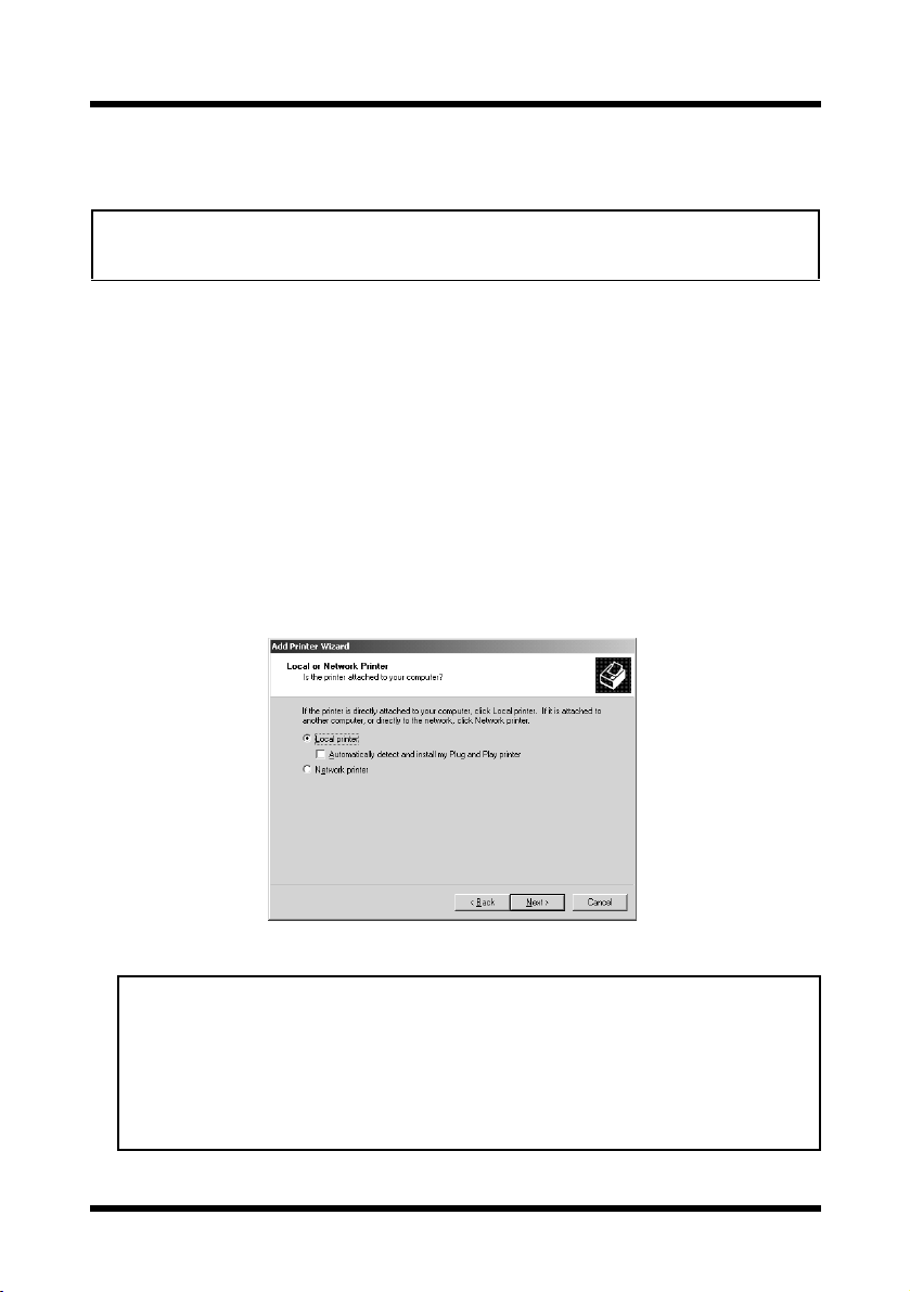
7. Select “
“
Local printer
Automatically detect and install my Plug and Play printer
button, point to
[Next]
button.
Add Printer
” and click the
[Settings]
” icon.
, and then click
[Next]
button. (Do not check the
Note
• For details on specifying network settings, refer to “7 Network
Printing in a Windows Environment” on page 49. Since other
network settings must first be specified, temporarily install the
printer driver under a local connection.
• For the network printer settings, consult with the network
administrator.
[Printers]
” box.)
.
10
Page 21

3 Installing the Printer Driver
8. Specify the port (LPT1, 2, etc.) where the print controller is connected.
[Next]
9. Click the
button.
10. Click the
11. Click the
[Have Disk]
[Browse]
button.
button.
12. Specify the printer driver directory on the CD-ROM for the environment being used, and then click the
[OK]
button. (Example: CD-ROM
drive\English\Win NT\PCL6\)
Then click the
13. Click the
[OK]
[Open]
button.
button.
14. Select the model of the copier you use.
[Next]
15. Click the
16. Specify the printer name and click the
Default: “
17. If you want the Digital copier to be the default printer select
not, select
18. Click the
19. Select “
Not shared
If you choose “
20. Click the
button.
Konica 7118 PCL6
[No]
.
[Next]
button.
Shared
” or “
[Next]
Shared
button.
”, specify the share name of the printer.
[Next]
Konica 7115 PCL6
” or “
” by clicking.
button.
”
[Yes]
; if
21. Select whether you will print the print test or not.
Select
[Yes]
to print the test page, or select
[No]
not to perform it.
22. Click the
[Finish]
button.
11
Page 22
3 Installing the Printer Driver
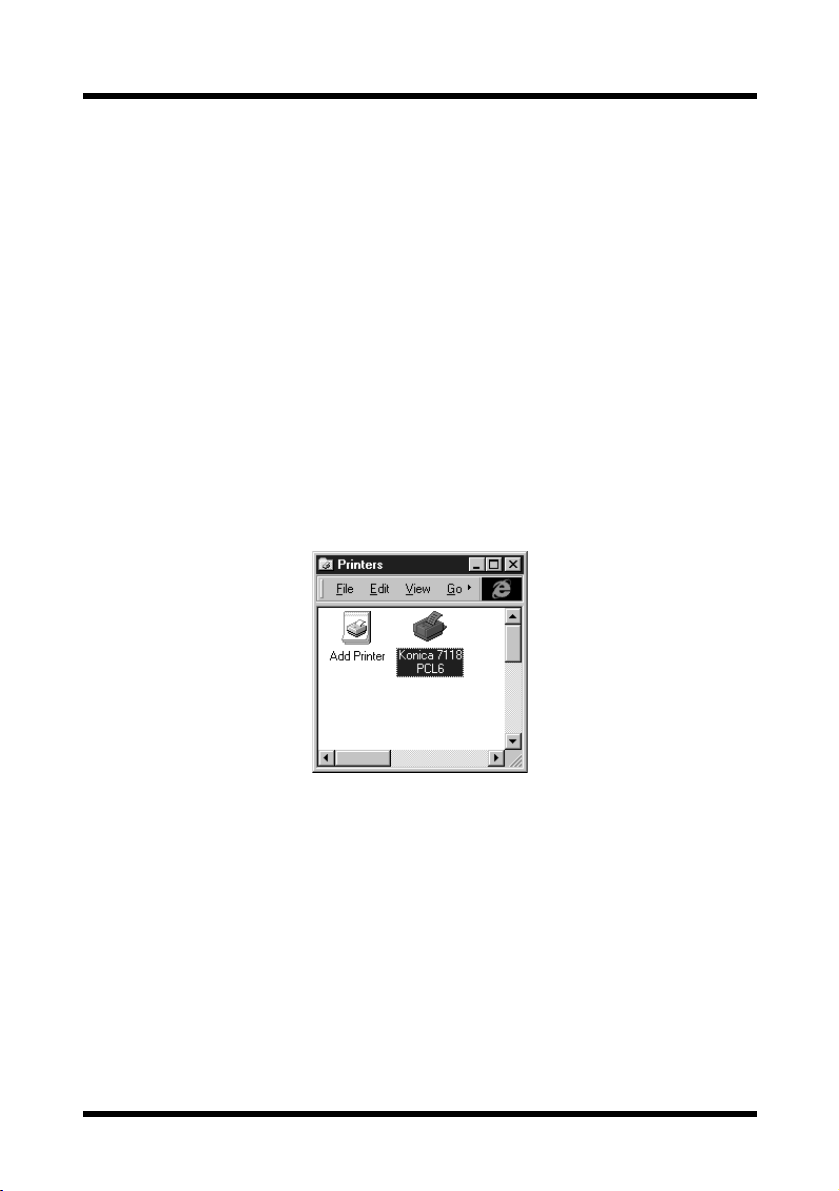
23. After installation is complete, check that the icon for the installed
printer appears in the “
24. Eject the CD-ROM from your computer’s CD-ROM drive.
This completes the installation of the printer driver.
Printers
” window.
12
Page 23
3 Installing the Printer Driver
3.4 Uninstalling the Printer Driver
If it is necessary to delete the printer driver, follow the procedure described
below.
1. Click the
2. In the “
[Start]
Printers
button, point to
[Settings]
” window, click the “
, and then click
Konica 7115 (7118) PCL6
[Printers]
” printer
icon.
3. Select “
Delete
” from the “
File
” menu.
4. Follow the instructions that appear on your computer screen to complete the uninstallation.
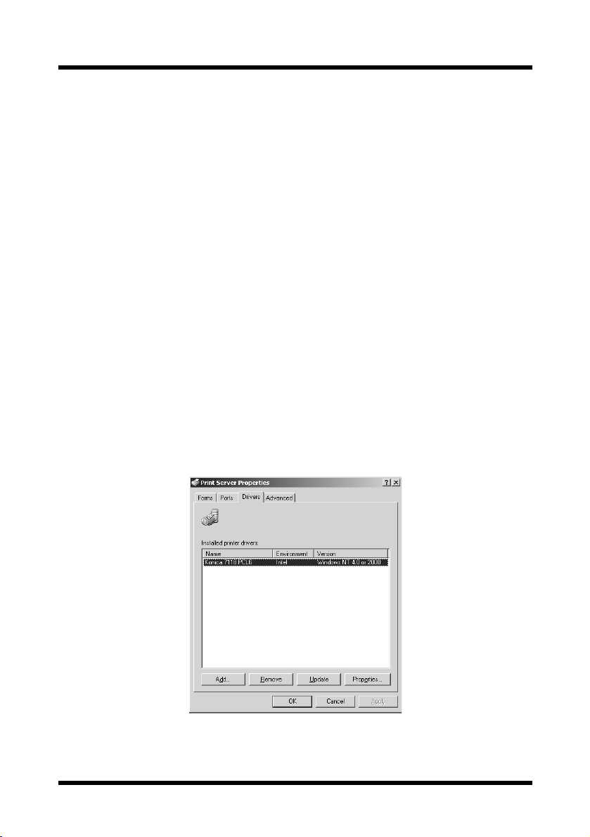
For Windows 2000, follow the procedure below.
For Windows 2000:
1. Click the
[Start]
button, point to
2. With no printer selected in the “
erties
” from the “
3. Display the
4. Select “
Konica 7115 (7118) PCL6
File
[Drivers]
” menu.
tab on the Print Server Properties dialog box.
[Settings]
Printers
, and then click
” window, select “
”, and then click the
[Printers]
Server Prop-
[Remove]
button.
.
.
13
Page 24
4 Printer Driver Settings
4 Printer Driver Settings
From the printer driver setup dialog, various printer settings can be specified
from the computer. The procedure for displaying this dialog and for
specifying the various settings in this dialog is described below.
4.1 Displaying the Printer Driver Setup Dialog
1. Click the
2. In the “
Printers
[Start]
button, point to
” window, click the “
[Settings]
, and then click
Konica 7115 (7118) PCL6
[Printers]
icon.
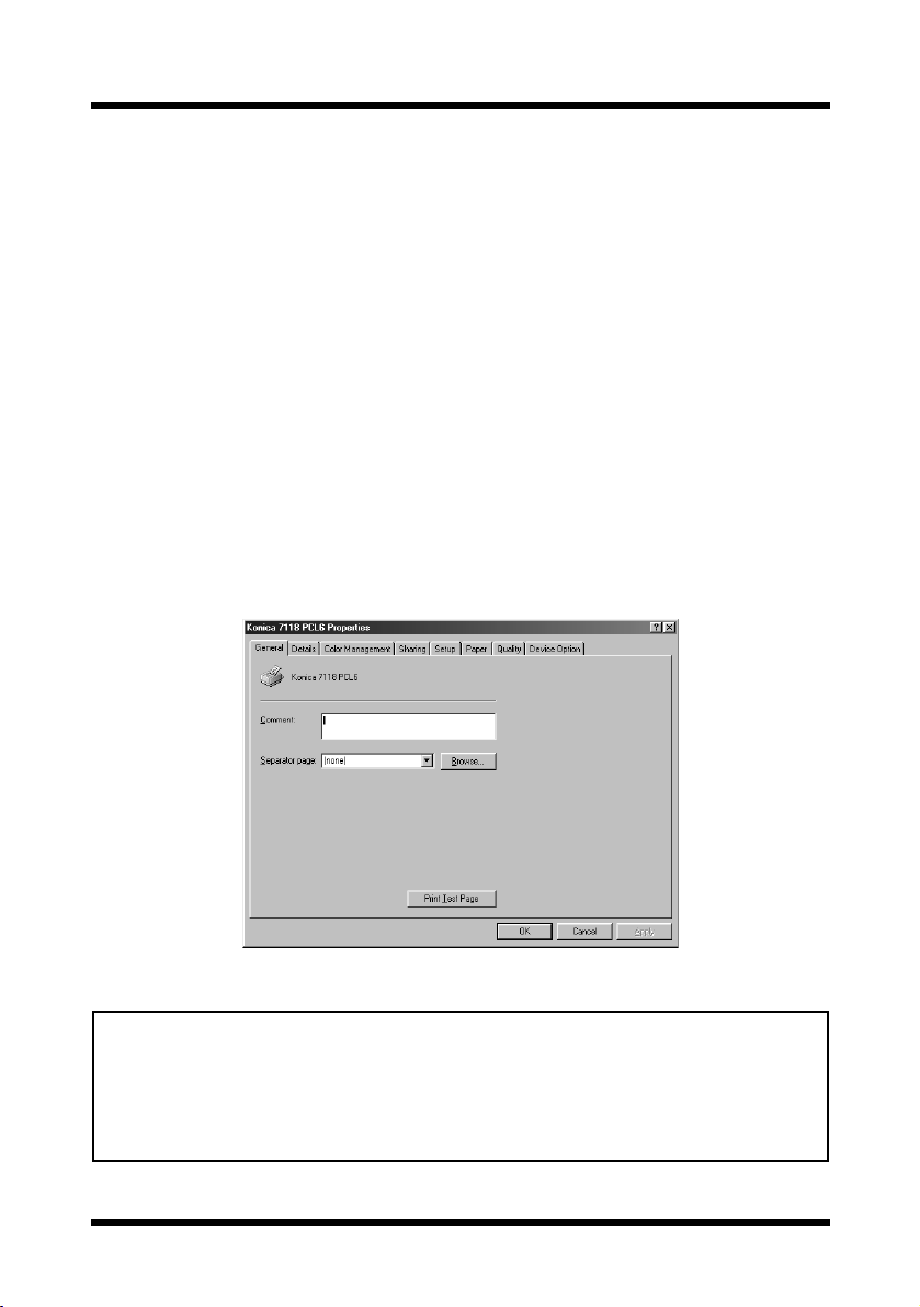
3. For Windows 95, 98 or Me, select “
For Windows NT 4.0, select “
For Windows 2000, select “
Documents Defaults
Printing Preference
Properties
” from the “
” from the “
” from the “
File
File
The following printer driver setup dialog appears:
Tip
• The tabs other than four tabs to the far right of this dialog differ
according to the computer’s operating system. With Windows NT 4.0
and 2000, these tabs do not appear.
• These four tabs can be viewed if the setup dialog is displayed by
clicking the [Properties] button in the application’s print dialog.
” printer
” menu.
File
” menu.
” menu.
.
14
Page 25

4 Printer Driver Settings
4.2 Common Settings
This section contains descriptions of the settings common to all the four tabs
(
[Setup], [Paper], [Quality]
OK
Click to exit the Properties dialog box, saving any changes made.
[Device Option]
, and
).
Cancel
Click to exit the Properties dialog box without saving any changes made.
Apply
Click to save all changes without exiting the Properties dialog box.
Easy Set
If some settings are changed, EasySet text box is change to
then
[Save]
button will be effective.
[Untitled]
To save the current settings, enter the name of the settings into the
EasySet text box, then click the
Select “
Factory’s Defaults
[Save]
button.
” from the drop-down list to reset the
functions of the tab to their original values.
If a setting is selected from the drop-down list, the button changed to
the
[Delete]
button. If the
[Delete]
button is clicked, the selected setting
is deleted.
,
15
Page 26

4 Printer Driver Settings
Page Layout/Printer Figure
Page Layout
If “
This allows you to check the paper size, and “
” is selected, a sample of the page layout is displayed.
N-up
” and “
settings.
If “
Printer Figure
” is selected, a diagram of the printer construction is
displayed. All installed options are displayed, and the tray currently
selected under “
Paper Source
” on the
[Setup]
tab (all trays if “
selected) appears in light blue.
4.3 Setup Tab
Watermark
Auto
”
” is
[Setup]
The
settings.
16
tab contains settings for N-up, Watermark and paper source
Page 27

4 Printer Driver Settings
4.3.1 N-up
Note
“N-up” cannot be set under the following conditions:
• When the “Output Paper Size” option on the [Paper] tab is checked
• When the “Scaling” setting on the [Paper] tab is specified
• When “Rendering Mode” on the [Quality] tab is set to “Send Page
as Raster”
From the drop-down list, select the number of pages to be printed on a single
sheet of paper. For example, if “
divided in half so that two pages can print on it. If “
page is printed on a single sheet of paper.
Border Line
Check this option to print a border around each page when multiple
pages are printed on a single sheet of paper.
N-up Style
If this button is clicked, the following dialog appears.
2-up
” is selected, one sheet of paper is
Off
” is selected, only one
When multiple pages are printed on a single sheet of paper, the
orientation to order for printing the pages can be set. Refer to the
diagrams and select the desired setting.
17
Page 28

4 Printer Driver Settings
4.3.2 Watermark
You can place watermarks on a document to quickly alert the reader to the
nature of its content. For example: CONFIDENTIAL, DRAFT, etc. Select a
watermark you wish to use in the drop-down list.
First Page Only
A watermark can be specified to appear on the first page only of a
multi-page document by checking this option. Otherwise, a watermark
that is specified to appear will be placed on every page of the multipage document.
Edit Watermark
Click this button to open the Watermark Settings dialog.
When editing a watermark, select the watermark in the “
Watermark
” list, and then make the desired settings. In addition, you
Select a
can double click a watermark in the list to change the watermark text.
New
To create a new watermark, click the
[New]
button. A dialog that allows
you to type in the text for the watermark appears. Type in the watermark
text that you wish to be printed on the paper. The text for the watermark
can only contain 31 characters. A maximum of 32 different watermarks
can be specified.
18
Page 29

4 Printer Driver Settings
Delete
To remove a watermark, select the watermark that you wish to remove
from the list, click the
Font
To specify the font for a watermark, select the watermark from the
drop-down list, and then click the
appears.
[Delete]
button.
[Font]
button. The Font dialog
Font:
Font style:
Size:
Script:
Sample:
Angle
The font of the watermark is specified here.
The font style of the watermark is specified here.
Select or type in the font size of the watermark (between 20
and 200 points).
Select the type of the Symbol set.
A sample of the specified settings can be viewed here.
The angle at which the watermark is printed on the paper can be set
between -180° and +180°.
Darkness
The density at which the watermark is printed can be set between -10
and +10.
19
Page 30

4 Printer Driver Settings
X-Offset/Y-Offset
Move the scroll box to the desired horizontal/vertical location to adjust
the position of the watermark in the document.
Check “
Automatic Center to Page
” to print the watermark in the center
of the document.
Default
Click this button to return settings to their initial factory defaults.
4.3.3 Paper Source
The Paper Source item specifies the tray from which paper is fed from the
Digital Copier. Select the desired paper source (and media type) from the
drop-down list.
Auto
If “
automatically selected.
” is selected, the tray containing the paper of the specified size is
If “
Tray1
” or “
Bypass
” is selected, the paper type (plain paper, thick paper,
or OHP) can also be specified.
Note
• If the desired tray is an option and does not appear as a paper
source, make sure that it has been added in the [Device Option] tab.
Detail of Paper Source
If the first or last page is to be supplied from a tray different from the
tray supplying paper for the rest of the document, click this button. The
Detail Of Paper Source dialog appears.
20
Page 31

4 Printer Driver Settings
Front Cover Page
Check this option when printing the first page on paper from a different
paper tray.
Back Cover Page
Check this option when printing the last page on paper from a different
paper tray.
With Image
Check this option to print the front/back cover page.
Cover Paper Source
Select the paper tray for printing the specified front/back cover page.
4.4 Paper Tab
[Paper]
The
documents.
tab contains functions that affect the output of your printed
4.4.1 Original Document Size
The various sizes of paper that are supported by your printer are displayed in
the drop-down list. Select the document size.
21
Page 32

4 Printer Driver Settings
Edit Custom
Click this button to add a paper size to the “
drop-down list or to change an existing custom paper size. The dialog
that allows you to specify custom paper sizes appears.
New
To add a custom paper size, click the
Edit
To change a custom paper size that has already been defined, select the
desired paper name, and then click the
Delete
To delete a custom paper size from the list, select the desired paper
name, and then click the
[Delete]
button.
Original Document Size
[New]
button.
[Edit]
button.
”
When the
[New]
the bottom of the dialog.
22
or
[Edit]
button is clicked, additional settings appear at
Page 33

4 Printer Driver Settings
Enter the name of the custom size into the “
characters). Next, specify either “
the dimensions for “
Width
” and “
mm
Height
Name
inch
” or “
”. Click the
” box (maximum 40
Unit
” in “
”, then enter
[OK]
button at the
bottom of the dialog. The custom size will be added to the above list.
Note
• The paper width can be set between 90 and 297 mm (3.54 and 11.69
inches), and the length can be set between 140 and 432 mm (5.51
and 17.00 inches).
• Be sure that the setting for the “Height” is longer than the setting for
the “Width”.
• When using a custom size specified with the printer driver, be sure to
set that size first with the Digital Copier.
• If “Auto” is selected under “Paper Source” on the [Setup] tab, the
custom size cannot be used.
4.4.2 Output Paper Size
Note
No setting under “Output Paper Size” can be specified under the
following conditions:
• When the “N-up” setting on the [Setup] tab is specified to print
multiple pages on a single sheet of paper
• When “Rendering Mode” on the [Quality] tab is set to “Send Page as
Raster”
Output Paper Size
To print on paper with a size different from “
Original Document Size:
check this box, and then select the desired paper size from the dropdown list.
Fit to Paper
Check this option when you want the print image to be scaled to fit the
paper size specified in the “
Output Paper Size
” box. The image is
automatically enlarged or reduced to fit the paper size, and then printed.
In this case, the “
Scaling
” setting cannot be specified.
”,
23
Page 34

4 Printer Driver Settings
Scaling
The print area of the document can be enlarged or reduced. Enter a
value or use the arrow buttons to specify a scaling ratio (between 20%
and 400%).
4.4.3 Copies
This item specifies the number of copies to be printed. You can specify any
value from 1 to 999.
4.4.4 Collate at Printer
The Collate feature supports multi-document printing (when the number of
copies being output is two or more).
On
” is selected, multiple copies of the entire document are printed with
If “
each set containing all pages (1, 2, 3...1, 2, 3...1, 2, 3).
Off
” is selected, multiple copies of the document are printed with each
If “
set containing copies of the same page (1, 1, 1...2, 2, 2...3, 3, 3).
Note
• The “Collate at Printer” setting may not be available with some
applications.
• If “Off” is selected and the memory becomes full while data is being
received, print the received pages first. For example, if five copies
of a 10-page document are being printed, first print five copies of
pages 1 through 5, and then print five copies of pages 5 through
10.
4.4.5 Orientation
This function sets the orientation of the printed page to either “
“
Landscape
”.
24
Portrait
” or
Page 35

4 Printer Driver Settings
4.5 Quality
[Quality]
The
graphic quality of your printed documents.
4.5.1 Resolution
This printer prints at a resolution of 600 × 600 dpi.
tab allows you to make setting changes that enhance the
4.5.2 Toner Save
If “On” is selected for this option, less toner is used, thereby reducing printing
costs. However, text and images will be printed with a lighter density. If print
quality is considered to be more important, select “
Off
” for this option.
4.5.3 Rendering Mode
When “
raster graphics) are sent to the printer as raster (bitmapped) data. This can
cause printing to take longer than normal.
Send Page as Raster
Note
When “Rendering Mode” is set to “Send Page as Raster”, the
following items cannot be specified.
•“N-up” on the [Setup] tab
•“Output Paper Size” and “Scaling” on the [Paper] tab
•“Font Setting” on the [Quality] tab
” is selected, all objects (fonts, vector graphics,
25
Page 36

4 Printer Driver Settings
4.5.4 Font Setting
This setting allows you to specify how TrueType fonts will be handled when
text is printed.
Send TrueType as Bitmap
If “
” is selected, the text will be printed as
bitmapped data.
If “
Send TrueType as Outline
” is selected, the outline data will be printed as
it is.
4.5.5 Image Adjustment
[Image Adjustment]
If the
allowing you to specify the brightness and contrast.
Usually, the median values toward the center of the bars will provide the
best display. To fine tune these settings, click and hold on the sliders in order
to make left and right adjustments.
Drag the sliders or use to control the lighting of an image and tones in
terms of “
Click the
Brightness
[Default]
button to return settings to their initial factory defaults.
button is clicked, the following dialog appears,
” and “
Contrast
”.
26
Page 37

4.6 Device Option Tab
4 Printer Driver Settings
On the
For the “
[Device Option]
Installed Options
tab, specify the installed options.
” list, specify the options installed in your printer.
If optional trays are installed, be sure to change this setting.
To add an available option from the “
Installed Options
“
To remove an option from the “
click the
“
Installable Options
[Remove]
” list, select the option and click the
Installed Options
button. Removed options will be moved to the
” list.
Installable Options
” list, select the option and
” list to the
[Add]
button.
Note
• Trays that are not installed can be added to this dialog. However, if a
tray that is not installed is selected under “Paper Source” on the
[Setup] tab, the paper loaded in Tray 1 is used for printing.
About
Click this button to display version and copyright information about
this printer driver.
27
Page 38

5 Digital Copier Control Panel Operations (PC Print Mode)
5 Digital Copier Control Panel Operations
(PC Print Mode)
The control panel operations differ according to the functions of the Digital
Copier.
Refer to the page corresponding to the model being used.
• 7115/7118 “5.1 Operation Using the 7115/
7118” on page 28
• 7115F/7118F, or 7115/7118
with the fax unit installed
5.1 Operation Using the 7115/7118
When the print operation is executed from the computer, the Digital Copier
automatically switches to PC Print mode, and printing begins.
Prn
At this time, “
” appears in the display.
“5.2 Operation Using the 7115F/
7118F” on page 34
However, if a copy operation was performed, 30 seconds after copying is
finished, the mode changes and printing begins.
When printing is finished, the mode automatically switches to the Copy
mode.
In PC Print mode, cancelling the print job can be performed.
28
Page 39

5 Digital Copier Control Panel Operations (PC Print Mode)
5.1.1 Names of Control Panel Parts and Their Functions
1
4
4
1
2 3
2 3
No. Part Name Function
1
[PRINT]
indicator Displays the PC print status.
Refer to “5.1.2 [PRINT] Indicator/[START]
Key” on page 30.
2
[START]
key Lights up in orange to indicate that the Digital
Copier is in PC Print mode. Refer to “5.1.2
[PRINT] Indicator/[START] Key” on page 30.
3
[STOP]
key If pressed while the Digital Copier is in PC Print
mode, the current job is cancelled. Refer to
“5.1.3 Cancelling a Print Job” on page 30.
4Display “
Prn
” is displayed in the PC Print mode.
29
Page 40

5 Digital Copier Control Panel Operations (PC Print Mode)
5.1.2 [PRINT] Indicator/[START] Key
The status of PC printing can be checked with the indicator.
[PRINT]
indicator
Flashing Lit in green/
Lit Lit in orange Data received from computer is being
Off Lit in green There is no data received from the
[START] key’s
indicator
orange
Printing status
Receiving data from the computer
In addition, the received PC print data is
not yet printed.
printed.
No copy operation can be performed.
computer.
5.1.3 Cancelling a Print Job
PC printing of data can be cancelled from the control panel of the Digital
Copier. A print job can only be cancelled from the control panel while the
Digital Copier is in PC Print mode.
1. Check that the Digital Copier is in PC Print mode.
Prn
” appears in the display when
“
the Digital Copier is in PC Print
mode.
2. Press the
When a job is cancelled, “
If the PC printing data is lost when the job is cancelled, the Digital Copier
automatically returns to the mode it was in before entering PC Print mode.
[STOP]
key for 3 seconds.
Prn
” on the display flashes.
Note
• To cancel a print job when there is no paper, when there is a paper
size error or when loading paper into the manual bypass tray, hold
down the [STOP] key for 3 seconds.
• The print job cannot be cancelled while data is being received.
30
Page 41

5 Digital Copier Control Panel Operations (PC Print Mode)
5.1.4 Using Manual Bypass Tray
Follow the procedure described below to print onto paper fed manually, one
sheet at a time.
1. Specify the following setting in the printer setup dialog from the computer.
• Select “
Bypass
Paper Source
” in “
” on the
[Setup]
tab
2. Execute the print operation from the
computer.
[Add Paper]
The
indicator lights up
on the control panel.
3. Insert one sheet of paper into the manual bypass tray of the Digital Copier.
Documents are printed on paper
loaded into the manual bypass tray.
Note
• Be sure to execute the print operation from the computer, then load
the paper into the manual bypass tray. If the paper has already been
loaded, pull it out, and then insert it again.
• Load the paper into the manual bypass tray one sheet at a time.
• If the multiple bypass tray (optional) is installed, printing from it can be
performed in the same way as with any other paper tray since the
multiple bypass tray can hold 50 sheets of paper.
• When using a custom size specified with the printer driver, be sure to
set that size first with the Digital Copier.
31
Page 42

5 Digital Copier Control Panel Operations (PC Print Mode)
5.1.5 Outputting a Report
When the print controller is installed, the following reports can be outputted.
• Configuration Page
• PCL Font List
To Print the Configuration Page
1. Hold down the
for 3 seconds.
“
U--
” appears in the display.
2. Press the
[6]
key from the 10-Key
Pad.
3. Press the
“
4. Press the
[START]
L--
” appears in the display.
[1]
key from the 10-Key
Pad.
[AUTO RESET]
key.
key
5. Press the
[START]
key.
The Configuration Page will be printed.
Note
• During the first few minutes after the Digital Copier is turned on, “U-6”
may not appear and an error may be displayed.
32
Page 43

5 Digital Copier Control Panel Operations (PC Print Mode)
To Print the PCL Font List
1. Hold down the
for 3 seconds.
“
U--
” appears in the display.
2. Press the
[6]
key from the 10-Key
Pad.
3. Press the
“
4. Press the
[START]
L--
” appears in the display.
[2]
key from the 10-Key
Pad.
[AUTO RESET]
key.
key
5. Press the
[START]
key.
The PCL Font List will be printed.
Note
• During the first few minutes after the Digital Copier is turned on, “U-6”
may not appear and an error may be displayed.
33
Page 44

5 Digital Copier Control Panel Operations (PC Print Mode)
5.2 Operation Using the 7115F/7118F
When the print operation is executed from the computer, printing can begin
without the mode of the Digital Copier changing.
In Copy Mode
Printing begins 30 seconds after the copy
operation is finished.
In addition, if the
control panel is pressed, the Digital Copier
switches to PC Print mode and printing
begins. (For details about PC Print mode,
refer to “5.2.3 Switching to PC Print
Mode” on page 36.)
In Fax Mode
Printing can also be performed while the Digital Copier is in Fax mode. If a
received fax is being printed, PC print data will be printed after the Digital
Copier has finished printing the fax.
Whether in Copy mode or in Fax mode, the
current print status.
In PC Print mode, the print job can be cancelled.
[PRINT]
key in the
[PRINT]
indicator shows the
34
Page 45

5 Digital Copier Control Panel Operations (PC Print Mode)
5.2.1 Names of Control Panel Parts and Their Functions
1
2
1
2
5
5
34
34
No. Part Name Function
1
[PRINT]
indicator Displays the PC print status. Refer to “5.2.2
[PRINT] Indicator/[START] Key” on page 36.
2
[PRINT]
key Press to enter PC Print mode. Refer to “5.2.3
Switching to PC Print Mode” on page 36.
3 [START]
key Lights up in orange to indicate that the Digital
Copier is in PC Print mode. Refer to “5.2.2
[PRINT] Indicator/[START] Key” on page 36.
4
[STOP]
key If pressed while the Digital Copier is in PC Print
mode, the current job is cancelled. Refer to
“5.2.4 Cancelling a Print Job” on page 37.
5 Display Displays messages about the paper source and
paper size during PC Print mode.
35
Page 46

5 Digital Copier Control Panel Operations (PC Print Mode)
5.2.2 [PRINT] Indicator/[START] Key
The status of PC printing can be checked with the indicator.
[PRINT]
indicator
Flashing Lit in green/
Lit Lit in orange Data received from computer is
Off Lit in green There is no data received from the
[START]
key’s
indicator
orange
Printing status
Receiving data from the computer.
Received PC print data is not yet
printed.
being printed.
computer.
5.2.3 Switching to PC Print Mode
In PC Print mode, various operations can be performed, such as cancelling
the print job.
• Press the
[PRINT]
PC Print mode screen.
“
*PC PRINT*
play when the Digital Copier is in
PC Print mode.
key to display the
” appears in the dis-
Note
• If a print operation has not been executed at the computer,
pressing the [PRINT] key does not switch the Digital Copier to PC
Print mode.
36
Page 47

5 Digital Copier Control Panel Operations (PC Print Mode)
• In PC Print mode, the status of PC printing can be checked with the
message appearing in the bottom line of the display.
Message in bottom line
of display
RECEIVING
WAITING
PRINTING
Receiving data from the computer
Finished receiving data from the computer and
waiting to print
Printing data from the computer
• In PC Print mode, press the
[PRINT]
Printing status
key to return to the mode before
PC Print mode was entered. In addition, after PC printing is finished,
the mode automatically switches to the previous mode.
5.2.4 Cancelling a Print Job
PC printing of data can be cancelled from the control panel of the Digital
Copier.
1. Press the
Print mode.
“
*PC PRINT*
line of the display.
[PRINT]
key to enter PC
” appears in the top
2. Press the
The message “
appears.
[STOP]
key.
PC JOB CANCEL?
”
37
Page 48

5 Digital Copier Control Panel Operations (PC Print Mode)
3. Press the
When a job is canceled, “
CANCELED*
[YES]
key to cancel a job.
” appears in the
*JOB
bottom line of the Display for two
seconds.
If the PC printing data is lost when
the job is cancelled, the Digital
Copier automatically returns to the
mode it was in before entering PC Print mode.
Note
• The print job cannot be cancelled while data is being received.
5.2.5 Using Manual Bypass Tray
Follow the procedure described below to print onto paper fed manually, one
sheet at a time.
1. Specify the following setting in the printer setup dialog from the computer.
• Select “
Bypass
Paper Source
” in “
” on the
[Setup]
tab
38
Page 49

5 Digital Copier Control Panel Operations (PC Print Mode)
2. Execute the print operation from the
computer.
Regardless of the mode, the
message shown at the right appears
in the display of the Digital Copier.
3. Insert one sheet of paper into the manual bypass tray of the Digital Copier.
Paper loaded into the manual
bypass tray is printed on.
Note
• Be sure to execute the print operation from the computer, then load
the paper into the manual bypass tray. If the paper has already been
loaded, pull it out, and then insert it again.
• Load the paper into the manual bypass tray one sheet at a time.
• If the multiple bypass tray (optional) is installed, printing from it can be
performed in the same way as with any other paper tray since the
multiple bypass tray can hold 50 sheets of paper.
• When using a custom size specified with the printer driver, be sure to
set that size first with the Digital Copier.
39
Page 50

5 Digital Copier Control Panel Operations (PC Print Mode)
5.2.6 Outputting a Report
When the print controller is installed, the following reports can be outputted.
• Configuration Page
• PCL Font List
1. Press the
[CONFIRM]
key 3 times.
A confirmation message appears,
asking whether or not to print a
report.
2. Press the
[ENTER]
key.
A menu appears, showing the
reports and lists that can be printed.
3. Using the and keys, select the
report/list that you wish to print, and
then press the
[ENTER]
key.
• Configuration Page
• PCL Font List
After the specified report/list is
printed, the main screen appears again.
Note
• If the Digital Copier was just turned on, it may take a few minutes
before the menu is displayed.
40
Page 51

6 Digital Copier Settings for Use on a Network
6 Digital Copier Settings for Use on a
Network
Note
• If the Digital Copier is to be used as a printer on a network, the
optional network interface card KN-305 must be installed. The
network settings can only be specified when the network interface
card is installed.
The following network settings can be specified from the Digital Copier.
• IP address
• Subnet mask
• Default gateway
Note
• Network settings other than those listed above can be specified with
the Network Management Utility Light. For details, refer to the IP-413
Network Management Utility Light User’s Manual.
• If the IP address, subnet mask and default gateway are specified
using the Digital Copier, they can later be changed using Network
Management Utility Light.
• The network settings should be specified according to instructions
from the network administrator.
The control panel operations differ according to the functions of the Digital
Copier.
Refer to the page corresponding to the model being used.
• 7115/7118 “6.1 Specifying Settings Using
the 7115/7118” on page 42
• 7115F/7118F, or 7115/7118
with the fax unit installed
“6.2 Specifying Settings Using
the 7115F/7118F” on page 46
41
Page 52

6 Digital Copier Settings for Use on a Network
6.1 Specifying Settings Using the 7115/7118
6.1.1 IP Address
1. Hold down the
for 3 seconds.
“
U--
” appears in the display.
2. Press the
[6]
key from the 10-Key
Pad.
3. Press the
“
4. Press the
[START]
L--
” appears in the display.
[3]
key from the 10-Key
Pad.
[AUTO RESET]
key.
key
5. Press the
[START]
key.
6. The procedure differs depending on whether the IP address is automatically assigned or a fixed IP address is entered.
Assign automatically:
Fixed IP address:
Perform this procedure if there is a DHCP (Dynamic
Host Configuration Protocol) server on the network
and the IP address is automatically assigned by the
server.
Perform this procedure when assigning a fixed IP
address for the print controller.
42
Page 53

6 Digital Copier Settings for Use on a Network
• To assign the IP address automatically, press the
press the
“
Aut
[START]
key.
” appears in the display for two seconds, and then “
[1]
key, and then
U--
” appears.
With this procedure, it is not necessary to set the subnet mask and
gateway. For details on the next procedure, refer to “6.1.5 Restarting
the Digital Copier” on page 45.
• If a fixed IP address is to be used, refer to “6.1.2 Entering Values” on
page 43 and enter the value.
Note
• If the Digital Copier was just turned on, it may take a few minutes
before the settings can be specified.
6.1.2 Entering Values
This section describes the procedure for entering values for the IP address,
subnet mask and default gateway. These values consist of 12 digits separated
into sets of 3 digits. For each of these values, a 3-digit number will be
entered four times.
1. If a value has already been specified, it will appear in the display.
To change the value, press the
[CLEAR]
2. Using the 10-Key Pad, enter the 3digit number.
key.
3. Press the
[START]
key.
43
Page 54

6 Digital Copier Settings for Use on a Network
4. Repeat steps 2 and 3 three more times.
After the entire value has been entered, “
U--
” appears.
(Example) When entering the value 192.168.0.10:
6.1.3 Subnet Mask
1. Check that “
play, and then press the
U--
” appears in the dis-
[6]
key from
the 10-Key Pad.
2. Press the
“
L--
” appears in the display.
3. Press the
[START]
[4]
key.
key from the 10-Key
Pad.
4. Press the
[START]
key.
5. Refer to “6.1.2 Entering Values” on page 43 and enter a value for the
subnet mask.
6.1.4 Gateway
1. Check that “
play, and then press the
the 10-Key Pad.
U--
” appears in the dis-
[6]
key from
44
Page 55

6 Digital Copier Settings for Use on a Network
2. Press the
“
3. Press the
[START]
L--
” appears in the display.
[5]
key.
key from the 10-Key
Pad.
4. Press the
[START]
key.
5. Refer to “6.1.2 Entering Values” on page 43 and enter a value for the
default gateway.
6.1.5 Restarting the Digital Copier
After the IP address, subnet mask and default gateway have been set, the
Digital Copier must be restarted in order for the settings to become active.
U--
1. When “
press the
The display appears as shown at the
right.
” appears in the display,
[AUTO RESET]
key.
2. Turn off the Digital Copier.
3. Turn on the Digital Copier.
Note
• If a fixed IP address has been set, you must select “IP Address in
NVRAM” in the Network Management Utility Light. Make this
setting in the “TCP/IP Configuration” menu on the “Network” tab.
For more details, refer to the IP-413 Network Management Utility
Light User’s Manual.
45
Page 56

6 Digital Copier Settings for Use on a Network
6.2 Specifying Settings Using the 7115F/7118F
6.2.1 IP Address
The network settings are specified using the “
NETWORK(PRINT)
in INITIAL SET mode.
Tip
• If, at any time, you wish to quit setting a “NETWORK(PRINT)”
function, press the [NO] key. When the message “STOP SETTING?”
appears, press the [YES] key to quit.
Note
• If the Digital Copier was just turned on, it may take a few minutes
before the settings can be specified.
1. Press the
[INITIAL SET]
key.
The INITIAL SET menu screen
appears.
2. Using the and keys to display
NETWORK(PRINT)
“
3. Press the
to select “
[1]
key from the 10-Key Pad
IP ADDRESS
”.
”.
” function
4. Using the and keys, select
either “
then press the
• If “
AUTO
AUTO
” is selected, the IP address
” or “
[YES]
SPECIFY
key.
”, and
is automatically assigned by the
DHCP server. The “
(PRINT)
” menu appears again. For
NETWORK
details on the next procedure, refer to
“6.2.4 Restarting the Digital Copier”
on page 48.
46
Page 57

6 Digital Copier Settings for Use on a Network
SPECIFY
• If “
appears, allowing you to specify the
IP address. (Continue with step 5.)
Note
•“AUTO” is available when a DHCP server is on the network.
If “AUTO ” is selected, it is not necessary to set the subnet mask
and gateway.
5. Using the 10-Key Pad and the and
keys, enter the IP address.
• If an IP address has already been
entered, it can be overwritten.
• The screen at the right shows an
example of an entered IP address. For
values of settings, consult the network administrator.
” is selected, a screen
6. Press the
The “
[ENTER]
NETWORK(PRINT)
key.
” menu appears again.
6.2.2 Subnet Mask
1. With the “
of the Utility mode displayed, press
the
select “
2. Using the 10-Key Pad and the and
keys, enter the subnet mask value.
• The screen at the right shows an
example of an entered subnet mask
value. For values of settings, consult
the network administrator.
3. Press the
The “
NETWORK(PRINT)
[2]
key from the 10-Key Pad to
SUBNET MASK
[ENTER]
NETWORK(PRINT)
”.
key.
” menu appears again.
” menu
47
Page 58

6 Digital Copier Settings for Use on a Network
6.2.3 Default Gateway
1. With the “
NETWORK(PRINT)
” menu
of the INITIAL SET mode displayed,
press the
to select “
[3]
key from the 10-Key Pad
GATEWAY
”.
2. Using the 10-Key Pad and the and
keys, enter the default gateway
value.
The screen at the right shows an
example of an entered default
gateway value. For values of
settings, consult the network
administrator.
3. Press the
The “
[ENTER]
NETWORK(PRINT)
key.
” menu appears again.
6.2.4 Restarting the Digital Copier
After the IP address, subnet mask and default gateway have been set, the
Digital Copier must be restarted in order for the settings to become active.
1. With the “
displayed, press the
The message “
START
NETWORK(PRINT)
[NO]
PLEASE RE-
” appears.
” menu
key.
2. Turn off the Digital Copier.
3. Turn on the Digital Copier.
Note
• If a fixed IP address has been set, you must select “IP Address in
NVRAM” in the Network Management Utility Light. Make this
setting in the “TCP/IP Configuration” menu on the “Network” tab.
For more details, refer to the IP-413 Network Management Utility
Light User’s Manual.
48
Page 59

7 Network Printing in a Windows Environment
7 Network Printing in a Windows
Environment
Note
• If the Digital Copier is to be used as a printer on a network, the
optional network interface card KN-305 must be installed. In addition,
connect the printer to the network according to the procedure
described in “2.2 Connecting to the Ethernet 10/100Base-T Port
(Network Connection)” on page 4.
The network interface card KN-305 supports TCP/IP and IPX/SPX protocol.
7.1 Peer-to-Peer Printing (Windows 95/98/Me)
Peer-to-peer printing can be performed using TCP/IP.
7.1.1 Before You Begin
Check the following points.
• Specify the TCP/IP settings from the control panel of the Digital
Copier. At that time, specify a fixed IP address, not DHCP (automatic
setting). (Refer to “6 Digital Copier Settings for Use on a Network”
on page 41.)
• Check that the “
• Turn on the Digital Copier.
TCP/IP
” protocol has been installed on Windows.
7.1.2 Settings for Windows 95/98/Me
1. Install the printer driver for Windows 95/98/Me. For details on the
installation procedure, refer to “3.1 Windows 95/98/Me” on page 5.
During installation, set up the printer as a local printer.
2. Right-click the new printer icon and select “
3. Display the
4. Click the
The Add Port dialog box appears.
[Add Port]
[Details]
tab on the Properties dialog box.
button.
Properties
” from the menu.
49
Page 60

7 Network Printing in a Windows Environment
5. Click “
Other
”, select “
Peer2Peer
”, and then click the
[OK]
button.
A dialog that allows you to specify the port appears.
6. Enter the IP address specified on the Digital Copier into the “
Name
” box.
If the network you are on uses DNS (Domain Name System), you can
enter the DNS name instead of the IP address.
Printer IP/
7. Specify the necessary setting under “
[OK]
button.
8. Make sure that the new port is selected under “
port
”, and then click the
9. Display the
[General]
[Apply]
tab, and then click the
Port Name
button.
”, and then click the
Print to the following
[Print Test Page]
button to
print a test page.
10. If the test prints normally, complete the procedure by clicking the
[OK]
button to close the Properties dialog box.
After you finish installing a printer with the above procedure, you can use it
just as you would any standard local printer. The printer can also be used as
a network printer by other Windows computers on your network whose
Windows 95/98/Me systems are configured the same way as described
above.
50
Page 61

7 Network Printing in a Windows Environment
7.2 LPR Printing (Windows NT 4.0/2000)
This section explains how to use the Windows NT 4.0/2000 standard LPR
printing function.
7.2.1 Before You Begin
Check the following points.
• The TCP/IP settings should be specified from the control panel of the
Digital Copier. (Refer to “6 Digital Copier Settings for Use on a Network” on page 41.)
• For Windows NT 4.0, check that the “
“
Microsoft TCP/IP Printing
” service have been installed.
• For Windows 2000, check that the “
TCP/IP protocol
TCP/IP protocol
” and the
” has been
installed.
• Turn on the Digital Copier.
7.2.2 Settings for Windows NT 4.0
1. Install the printer driver for Windows NT 4.0. For details on the installation procedure, refer to “3.2 Windows NT 4.0” on page 7. During installation, set up the printer as a local printer.
2. Right-click the new printer icon and select “
[Ports]
3. Display the
4. Click the
[Add Port]
tab on the setting dialog box.
button.
Properties
The Printer Ports dialog box appears.
5. Select “
the
[New Port]
LPR Port
button.
” in the “
Available Printer Ports
6. In the Add LPR compatible printer dialog box, enter the IP address of
the Network Interface Card into the “
” field.
ing lpd
Name or address of server provid-
If the network you are on uses DNS (Domain Name System), enter
the DNS name instead of the IP address.
” from the menu.
” list, and then click
51
Page 62

7 Network Printing in a Windows Environment
7. Enter the name of the port you want into the “
queue on that server
8. Click the
[OK]
” box.
button to close the dialog box.
9. In the Printer Ports dialog box, click the
[OK]
10. Click the
button of the Properties dialog box to close it.
11. Right-click the printer icon again to select “
12. Display the
[General]
tab, click the
[Print Test Page]
Name of printer or print
[Close]
button.
Properties
” from the menu.
button to print a
test page.
13. If the test prints normally, complete the procedure by clicking the
[OK]
button to close the Properties dialog box.
After you finish installing a printer with the above procedure, you can use it
just as you would any standard local printer. The printer can also be used as
a network printer by other Windows computers on your network whose
Windows NT 4.0 systems are configured the same way as described above.
7.2.3 Settings for Windows 2000
1. Install the printer driver for Windows 2000. For details on the installation procedure, refer to “3.3 Windows 2000” on page 10. During installation, set up the printer as a local printer.
2. Right-click the new printer icon and select “
Ports
3. Display the “
4. Click the
[Add Port]
” tab on the setting dialog box.
button.
Properties
” from the menu.
The Printer Ports dialog box appears.
5. Select “
then click the
Standard TCP/IP Port
[New Port]
button.
” in the “
Available port types
” list, and
This starts the Add Standard TCP/IP Printer Port Wizard.
[Next]
6. Click the
7. On the “
Card into the “
Add Port
button on the introduction page of the wizard.
” page, enter the IP address of the Network Interface
Printer Name or IP Address
” box.
If the network you are on uses DNS (Domain Name System), you can
enter the DNS name instead of the IP address.
52
Page 63

7 Network Printing in a Windows Environment
8. Enter the name of the port you want into the “
click the
[Next]
button.
Port Name
” box, and then
Note
• When you enter the IP address into the “Printer Name or IP
Address” box, the name of the port is automatically entered in the
“Port Name” box as IP_ <IP address>. If you enter the DNS name
into the “Printer Name or IP Address” box, the same name is
automatically entered in the “Por t Name” box. You can change to
port name as desired.
9. On the “
and then click the
Additional Port Information Required
[Settings]
button.
” page, select “
Custom:
10. On the Configure Standard TCP/IP Port Monitor dialog box, select
LPR
” from the “
“
11. Type the name of the queue you want into the “
then check the “
12. Click the
[OK]
LPR Settings
LPR Byte Counting Enabled
” box.
Queue Name
” check box.
” box, and
button to return to the Additional Port Information
Required page.
[Next]
[Finish]
button.
button.
13. Click the
14. Click the
”,
15. Click the
16. Click the
[Close]
[Apply]
17. Display the
button of the Printer Ports dialog box.
button of the Properties dialog box.
[General]
tab, and then click the
[Print Test Page]
button to
print a test page.
18. If the test prints normally, complete the procedure by clicking the
[OK]
button to close the Properties dialog box.
After you finish installing a printer with the above procedure, you can use it
just as you would any standard local printer. The printer can also be used as
a network printer by other Windows computers on your network whose
Windows 2000 systems are configured the same way as described above.
53
Page 64

7 Network Printing in a Windows Environment
7.3 IPP Printing (Windows 2000)
This section explains how to use the Windows 2000 standard IPP printing
function.
7.3.1 Before You Begin
Check the following points.
• The TCP/IP settings should be specified from the control panel of the
Digital Copier. (Refer to “6 Digital Copier Settings for Use on a Network” on page 41.)
• The IPP settings should be specified using the Network Management
Utility Light. For details, refer to the IP-413 Network Management
Utility Light User’s Manual.
• Check that the “
TCP/IP protocol
” has been installed on Windows
2000.
• Turn on the Digital Copier.
7.3.2 Installing the Printer Driver
When the printer driver is installed, set up IPP printing.
1. Click the
2. Double-click the “
3. Click the
4. On the “
option, and then click the
5. On the “
the Internet or your intranet
6. Type the IPP printer’s URL into the “
then click the
[Start]
button, point to
Add Printer
[Next]
button.
Local or Network Printer
Locate Your Printer
[Next]
button.
http://
<IP address of the Network Interface Card>
[Settings]
, and then click
” icon to start the Add Printer Wizard.
” page, select the “
[Next]
button.
” page, select the “
Connect to a printer on
” option.
URL
” box as shown below, and
[Printers]
Network printer
/ipp.cgi
.
”
54
Page 65

7 Network Printing in a Windows Environment
(Example) When the IP address of the Network Interface Card is
192.168.0.10:
http://192.168.0.10/ipp.cgi
If the network you are on uses DNS (Domain Name System), enter the
DNS name instead of the IP address.
7. Click the
8. Click the
9. Click the
[OK]
button on the confirmation dialog box that appears.
[Have Disk]
[Browse]
button.
button and specify the location of the printer driver’s
INF file on the CD-ROM.
10. Select whether you use this printer as the default printer or not, and then
[Next]
click the
11. Click the
12. Right-click the new printer icon and select “
13. Display the
button.
[Finish]
[General]
button to exit the wizard.
tab, and then click the
Properties
[Print Test Page]
” from the menu.
button to
print a test page.
14. If the test prints normally, complete the procedure by clicking the
[OK]
button to close the Properties dialog box.
After you finish installing a printer with the above procedure, you can use it
just as you would any standard local printer.
7.4 Printing via a NetWare Server
The procedure for using Windows to print on a printer connected to a
NetWare server is described below.
7.4.1 Before You Begin
Check the following points.
• The TCP/IP settings should be specified from the control panel of the
Digital Copier. (Refer to “6 Digital Copier Settings for Use on a Network” on page 41.)
55
Page 66

7 Network Printing in a Windows Environment
• The NetWare settings should be specified using the Network Manage-
ment Utility Light. For details, refer to the IP-413 Network Management Utility Light User’s Manual.
• With the NetWare server, specify the print queue, print server and the
printer structure settings. For details, refer to the NetWare manual.
• For Window 95/98/Me, check that the “
col
” and “
Client for NetWare Networks
IPX/SPX-compatible Proto-
” have been installed on Win-
dows. For details, refer to the Windows manual.
• For Window NT 4.0, check that the “
Client Service for NetWare
” has
been installed on Windows. For details, refer to the Windows NT 4.0
manual.
• Turn on the Digital Copier.
7.4.2 Settings for Windows 95/98/Me
1. Install the printer driver for Windows 95/98/Me. For details on the
installation procedure, refer to “3.1 Windows 95/98/Me” on page 5.
During installation, set up the printer as a local printer.
2. Right-click the new printer icon and select “
3. Display the “
4. Click the
[Add Port]
Details
” tab on the Properties dialog box.
button.
Properties
The Printer Ports dialog box appears.
5. Click the
[Browse]
button.
The Browse for Printer dialog box appears.
6. In the network computers, select the printer icon labeled with the Netware print queue you will use.
” from the menu.
[OK]
7. Click the
8. Click the
9. Display the
button twice to close the dialog box.
[Apply]
button.
[General]
tab, and then click the
[Print Test Page]
button to
print a test page.
10. If the test prints normally, complete the procedure by clicking the
button to close the Properties dialog box.
56
[OK]
Page 67

7 Network Printing in a Windows Environment
7.4.3 Settings for Windows NT 4.0/2000
When the printer driver is installed, specify the NetWare printer.
1. Click the
2. Double-click the “
3. Click the
4. On the “
option, and then click the
5. Click the
6. In the “
[Start]
button, point to
Add Printer
[Next]
button.
Local or Network Printer
[Next]
[Next]
button.
Shared printers
” list on the “
[Settings]
, and then click
[Printers]
” icon to start the Add Printer Wizard.
” page, select the “
Network printer
button.
Browse for Printer
” page, select the
.
”
printer icon labeled with the Netware print queue you will use.
[Next]
7. Click the
8. Click the
9. Click the
10. Click the
button.
[OK]
button on the confirmation dialog box that appears.
[Have Disk]
[Browse]
button.
button and specify the location of the printer driver’s
INF file on the CD-ROM.
11. Select whether you use this printer as the default printer or not, and then
[Next]
click the
12. Click the
13. Right-click the new printer icon and select “
14. Display the
button.
[Finish]
[General]
button to exit the wizard.
tab, and then click the
Properties
[Print Test Page]
” from the menu.
button to
print a test page.
15. If the test prints normally, complete the procedure by clicking the
button to close the Properties dialog box.
[OK]
57
Page 68

8 Troubleshooting
8 Troubleshooting
If a problem occurs during PC printing, check the following.
The control panel operations differ according to the functions of the digital
copier. Refer to the page corresponding to the model being used.
• 7115/7118 “8.1 Correcting Errors for the
• 7115F/7118F, or 7115/7118
with the fax unit installed
7115/7118” on page 58
“8.2 Correcting Errors for the
7115F/7118F” on page 60
8.1 Correcting Errors for the 7115/7118
If a PC print error occurs with the 7115/7118, the error appears in the
display.
For paper jam, paper size, paper empty, or replenish toner errors, the error
will appear in the display or control panel as it would if the Digital Copier
was in Copy mode.
8.1.1 Main Error Messages
The error messages that may appear during PC Print mode are described
here.
For details about error messages that also appear during Copy mode, refer to
the 7115/7118 User’s Manual.
Error Display Cause Remedy
If the optional Job Tray is
installed and the paper in the
Upper Copy Tray has reached
the maximum capacity,
printing cannot continue.
Auto
” is selected under
“
Paper Source
“
driver, but paper of a suitable
size is not loaded.
” in the printer
Remove all paper from the
Upper Copy Tray of the Job
Tray.
Load paper of the indicated
size.
Otherwise, press the
key to print on paper that is
currently loaded.
[START]
58
Page 69

8 Troubleshooting
Error Display Cause Remedy
Paper of the size specified in
the printer driver is not loaded
into the specified paper tray.
The type of paper specified
with the printer driver is
different from the type of paper
specified with the paper tray.
The optional Job Tray is
installed and the paper in either
the Upper Copy Tray or the
Lower Copy Tray has reached
the maximum capacity.
Load the specified size of
paper into the specified paper
tray.
Otherwise, press the [START]
key to print on paper that is
currently loaded.
To change the paper type
setting for the Digital Copier,
use the Utility mode.
To print on the type of paper
specified with the Digital
Copier, press the
to begin printing.
Remove the paper from the
Upper Copy Tray or the Lower
Copy Tray of the Job Tray, and
then press any key on the
operation panel.
[START]
key
59
Page 70

8 Troubleshooting
8.2 Correcting Errors for the 7115F/7118F
If a PC print error occurs in a mode other than the PC Print mode, “
appears in the bottom-right corner of the Digital Copier’s display.
<In Copy Mode>
<In Fax Mode>
PC Err
8.2.1 Checking Error Messages
PC Err
If “
display in a mode other than the PC Print mode, the error message can be
checked in PC Print mode.
1. Press the
” appears in the bottom-right corner of the Digital Copier’s
[PRINT]
Panel of the Digital Copier to enter
PC Print mode.
key on the Control
”
60
*PC PRINT*
“
line of the Display, and an error
message appears in the bottom line.
” appears in the top
Page 71

8 Troubleshooting
8.2.2 Main Error Messages
The error messages that may appear during PC Print mode are described
here.
For details about error messages that also appear during Copy mode, refer to
the 7115F/7118F(FK-117) User’s Manual.
Message Cause Remedy
UPPER TRAY FULL
(Flashing alternately)
REMOVE PAPER
NO SUITABLE PAPER
(Flashing alternately)
LOAD XXX
(CONTINUE=START)
INCORRECT PAPER SIZE
(Flashing alternately)
CHANGE #XXX → #XXX
MEDIA TYPE ERROR
(Flashing alternately)
CHANGE #XXX → #XXXx
TRAY MOVEMENT
ERROR
(Flashing alternately)
PRESS ANY KEY
If the optional Job Tray is
installed and the paper in
the Upper Copy Tray has
reached the maximum
capacity, printing cannot
continue.
Auto
“
” is selected under
Paper Source
“
” in the
printer driver, but paper of
a suitable size is not
loaded.
XXX
“
” indicates the paper
size.
Paper of the size specified
in the printer driver is not
loaded into the specified
paper tray.
“#” indicates the paper tray,
XXX
and “
” indicates the
paper size.
The type of paper specified
with the printer driver is
different from the type of
paper specified with the
paper tray.
“#” indicates the paper tray,
XXX
and “
” indicates the
paper size.
“x” indicates the media
type. O=OHP, C=Thick
Paper
The optional Job Tray is
installed and the paper in
either the Upper Copy Tray
or the Lower Copy Tray
has reached the maximum
capacity.
Remove all paper from the
Upper Copy Tray of the
Job Tray.
Load paper of the indicated
size.
Otherwise, press the
[START]
key to print on
paper that is currently
loaded.
Load paper of the indicated
size.
Otherwise, press the
[START]
key to print on
paper that is currently
loaded.
To change the paper type
setting for the Digital
Copier, use the Utility
mode.
To print on the type of
paper specified with the
Digital Copier, press the
[START]
key to begin
printing.
Remove the paper from the
Upper Copy Tray or the
Lower Copy Tray of the
Job Tray, and then press
any key on the operation
panel.
61
Page 72

9 Appendix
9Appendix
9.1 Assigning IP Parameters Using Initializer
Initializer is a utility for assigning IP parameters to a Network Interface
Card (NIC). When Initializer is run on a computer, an Initializer request
from a NIC causes IP parameters that match the MAC address of the NIC to
be assigned to the NIC.
Requirements
• Computer must have TCP/IP installed and enabled.
• NIC must be connected to the same subnetwork as the computer run-
ning Initializer.
Note
• Initializer does not operate properly on a computer running a DHCP
server.
9.1.1 Using Initializer
1. To check the MAC address (Network Address) of the NIC, print out the
Configuration Page.
For details on printing the Configuration Page, refer to “5.1.5
Outputting a Report” on page 32 or “5.2.6 Outputting a Report” on
page 40.
2. On the computer you want to use, maneuver to the directory you want
and copy the “
The “
ROM.
3. Double-click “
The Initializer dialog box appears.
4. Reset the Digital Copier by powering it off and then back up again. The
above step outputs a fixed-period Initializer request.
5. Wait for about five minutes until the NIC resets.
6. Click the
initialize.exe
initialize.exe
initialize.exe
[Next]
button.
” file to it.
” file is located in the root directory on the CD-
”.
62
Page 73

9 Appendix
7. Enter beside “
MAC address
” the MAC address specified on the Config-
uration Page printed in step 1, or select the MAC address from the list.
Note
• Use colons to separate each octet in the MAC address as shown
on the Configuration Page.
8. Click the
[Next]
button.
9. Enter the following parameters.
•
IP address
IP address assigned to the NIC
•
Subnet mask
Subnet mask value of connected network
•
Default gateway
Router IP address of connected network
10. Click the
[Next]
button.
11. Display the MS-DOS prompt and type the following:
<IP address of the NIC>
ping
12. Repeat step 11 until a response is received. Configuration is complete
when a response starting with the words “
Reply from...
” is returned.
13. On the Initializer dialog box, click the
[Exit]
button.
63
Page 74

9 Appendix
9.2 Specifications
Print Speed 7115/7115F: 15 pages/min. (A4)
7118/7118F: 18 pages/min. (A4)
Resolution
CPU Motorola MPC8240 (200 MHz)
RAM 32 MB (Max. 160 MB)
Protocol TCP/IP*, IPX/SPX*
Interface IEEE1284, 10/100Base-T*
Printer Language PCL6, PCL5e
Fonts PCL Fonts (45 fonts), Bitmap Fonts (8 fonts)
Operating System Windows 98/95/Me, Windows NT 4.0/2000
Accessories Network Interface Card (KN-305)
* Requires the optional Network Interface Card (KN-305)
600 dpi
× 600 dpi
64
Page 75

9.3 IP-413 Printer Configuration Page
Printer Information
Printer F/W: x.xx
Master F/W: x.xx
Panel Language: US-English
Total Count: 001432
Paper Size Count: 000108
Printer Configuration
Printer Memory: 96 Mbyte
Tray 1: A4
Tray 2: A4
Tray 3: A4
Tray 4: A3
Tray 5: B4
Bypass: Installed
Output Tray: Separator
Network: Ethernet
PCL Settings
Paper size: A4
Orientation: Portrait
Copies: 1
Paper Source: Tray 1
Font Name: Courier
Size: 12.00
Pitch: 10.00
Symbol set: PC-8
Form Length: 64
9 Appendix
Network Configuration
Network Firmware: x.xx
Network Address: xx:xx:xx:xx:xx:xx
Network Speed: Auto
TCP/IP Network Information:
Protocol Address: xxx.xxx.xxx.xxx
Subnetmask: xxx.xxx.xxx.xxx
Default Gateway: xxx.xxx.xxx.xxx
IPP: http://xxx.xxx.xxx.xxx/ipp.cgi
Novell Network Information:
Print Server Name:
Password Defined: No
Preferred Server Name:
Connection Mode: Directory Services
Preferred NDS Tree:
Enabled
Disabled
65
Page 76

9 Appendix
9.4 IP-413 PCL Font List
66
Page 77

MEMO
67
Page 78

MEMO
68
Page 79

 Loading...