

Konica Minolta MULTI GLOSS 268, UNI GLOSS 60A, UNI GLOSS 60CT, UNI GLOSS 60S Instruction Manual

Instruction Manual
Betriebsanleitung
Mode d´emploi
MULTI GLOSS 268
UNI GLOSS 60
MULTI GLOSS 268A
UNI GLOSS 60A
UNI GLOSS 60CT
UNI GLOSS 60S
Instruction Manual
1
Instruction Manual
Patent pending
260 023 933 E 1609
MULTI GLOSS 268A
UNI GLOSS 60A
UNI GLOSS 60CT
UNI GLOSS 60S

2

3
Table of content
Table of content
1. Safety Symbols ......................................................................................6
2. Safety Precautions .................................................................................7
3. Notes on Use...........................................................................................8
4. System description .............................................................................. 13
5. Power supply........................................................................................ 14
5.1 Power supply battery-operated ............................................................ 14
5.2 Changing the battery ............................................................................. 15
5.3 External power supply........................................................................... 15
6. Controls ................................................................................................. 16
7. Getting started ...................................................................................... 18
7.1 Turning on the unit and measuring ....................................................... 18
7.2 Navigation ............................................................................................... 19
7.3 Change names/numbers ....................................................................... 20
7.4 Overview of main menu ......................................................................... 21
8. Calibrate ............................................................................................... 22
8.1 Autodiagnosis ........................................................................................ 22
8.2 Calibrate ................................................................................................. 23
8.2.1 Gloss ........................................................................................... 23
8.2.2 Change cal.values ....................................................................... 24
8.2.3 Status ........................................................................................... 25
8.2.4 Scale Gloss ................................................................................. 25
8.3 Calibrating standards ............................................................................ 26
8.4 Checking standard ................................................................................ 26
9. Measurement techniques .................................................................... 27
9.1 Paints and varnishes, plastics and similar materials ......................... 27
9.2 Anodized aluminum and other metal surfaces .................................... 28
10. Measurement Modes ........................................................................... 29
10.1 Sample mode ......................................................................................... 29

4
Table of content
10.2 Statistics ................................................................................................ 30
10.2.1 Number of measurements .......................................................... 31
10.2.2 Display ......................................................................................... 31
10.2.3 Exit block ...................................................................................... 33
10.2.4 Delete block ................................................................................. 33
10.2.5 Delete measurement .................................................................. 33
10.3 Continuous ............................................................................................. 34
10.4 Basic mode ............................................................................................ 35
11 Geometry ..............................................................................................36
11.1 Geometry selection ............................................................................... 36
12. Memory ................................................................................................. 37
12.1 Memory................................................................................................... 37
12.2 Select memory ....................................................................................... 37
12.3 Create memory ...................................................................................... 38
12.4 Delete memory....................................................................................... 38
12.5 Display memory ..................................................................................... 38
13. Difference measurement and Pass/Fail ............................................ 40
13.1 Difference ............................................................................................... 40
13.2 Measure standard ................................................................................. 40
13.3 Select standard ..................................................................................... 41
13.4 Create standard ..................................................................................... 42
Define standard .............................................................................................. 42
13.5 Change standard ................................................................................... 43
13.6 Delete standard ..................................................................................... 43
14. Setup ..................................................................................................... 44
14.2 Date/Time ............................................................................................... 44
14.3 Beeper .................................................................................................... 44
14.4 Display time ............................................................................................ 44
14.5 Language................................................................................................ 45
14.6 Info .......................................................................................................... 45
15. Interface ................................................................................................ 46
16. Standards..............................................................................................47
17. Specifications ....................................................................................... 48

5
Table of content
18. Accessories ........................................................................................... 49
19. Errors and warning messages ............................................................ 50
20. Cleaning and maintenance ................................................................ 52
21. Copyright .............................................................................................. 53
6
1. Safety Symbols
The following symbols are used in this manual and
the instrument to prevent accidents which may
occur as a result of incorrect use of the instrument.
• Denotes a sentence regarding a safety warning
or note. Read the sentence carefully to ensure
safe and correct use.
• Denotes a prohibited operation. The operation
must never been performed
• Denotes a prohibited operation. Never
disassemble the instrument.
• This symbol indicates direct current (DC).
Notes on this manual
• Copying or reproduction of all or any part of the
contents of this manual without permission of the
manufacturer is strictly prohibited.
• The contents of this manual are subject to
change without prior notice.
• Every effort has been made in the preparation of
this manual to ensure the accuracy of its
contents. However, should you have any
questions or find any errors, please contact the
store where you purchased the instrument.
• The manufacturer will not accept any
responsibility for consequences arising from the
use of the instrument.
Safety Symbols

7
2. Safety Precautions
To ensure correct use of this instrument, read the following points carefully and
adhere to them. After you have read this manual, keep it in a safe place where
it can be referred to anytime a question arises. If you pass this instrument to
somebody else, make sure to include these instructions.
Safety Precautions
Do not use the instrument in
places where flammable or
combustible gases (gasoline
etc.) are present. Doing so may cause fire.
Do not disassemble or modify
the instrument or the Power
supply. Doing so may cause a
fire or electric shock.
Take special care not to allow
liquid or metal objects to enter
the instrument. Doing so may
cause a fire or electric shock. Should liquid
or metal objects enter the instrument,
disconnect the Power supply from the AC
outlet immediately, and contact the store
where you purchased the instrument.
The instrument should not be
operate if it is damaged, or if
smoke or odd smells occur.
Doing so may result in a fire. In such
situations, remove the battery and/or
immediately disconnect the USB interface
cable, and contact the company where you
purchased the instrument.
CAUTION (Failure to adhere to the following points may result in injury
or in damage to the instrument or other property)
Do not use batteries other
than those specified. When
installing batteries in the
instrument, make sure that they are correctly
oriented according to the (+) and (-) marks.
Failure to adhere to these instructions may
cause batteries to explode or leakage of
electrolytes, resulting in fire, injury or air
pollution.
Only devices that meet the
requirements for low-voltage
safety can be connected to the
USB interface.
WARNING (Failure to adhere to the following points
may result in death or serious injury.)
Do not dispose of batteries in
fire, short the terminals, apply
heat to them, or disassemble
them. Also, do not recharge them. Doing so
may cause explosion or heat generation,
resulting in fire or injury.
Do not touch the battery with wet
hands. Doing so may cause
electric shock.

8
Notes on Use
3. Notes on Use
• The measurement unit consists of sensitive
precision optical and electronic parts.
Do not drop it. Protect it from being bumped or
jostled.
• Do not hold the unit by the measurement
aperture. You should not allow any foreign
objects to get into this opening.
• Do not expose the unit to direct sunlight for
extended periods of time. Do not store it in a hot
or dusty environment. The case that comes with
the unit offers the best protection when the unit
is being stored.
• Avoid prolonged high relative humidity and do not
allow condensation to form.
• Protect the measuring unit from moisture,
chemicals and corrosive vapors.
• The holder and the unit housing are resistant to a
number of solvents. However, we cannot
guarantee resistance to all chemicals. You
should therefore use a soft, moist cloth for
cleaning. For clean excessive dirt and dust, use
ethanol or cleaning alcohol.
Do not use any acetone!
• If you will not be using the measuring unit for an
extended period of time, remove the battery to
prevent it from leaking in the unit and thus
potentially causing damage.

9
Notes on Use
• Do not replace the internal backup battery
yourself. Contact the nearest authorized service
facility to replace the backup battery.
• If the instrument is subjected to strong static
electricity, the display may become blank. If this
occurs, wait for the power to be automatically
switched off, and then switch the power on
again.
• Do not perform any repairs on the unit yourself.
The unit must be opened by trained professions
only. Please contact our customer service
department in such cases.
• Do not use accessories other than those
specified by KONICA MINOLTA INC.
• Pollution degree 2: Use it in areas where there is
no metal dust and no possibility of condensation.
• Do not use at altitudes of higher than 2000m.
Additional information on use:
• Make sure that the instrument, accessories and
used battery are either disposed of or recycled
correctly in accordance with local laws and
regulations.
10
For EU member states only:
This symbol means: Do not dispose of this product
together with your household waste.
Please refer to the information of your local
community or contact our dealers regarding the
proper handling of end-of-life electric and electronic
equipment.
Recycling of this product will help to conserve
natural resources and prevent potential negative
consequences for the environment and human
health caused by inappropriate waste handling.
For EU member states only:
This symbol on the batteries or on the packaging
indicates that the batteries provided with this
product shall not be disposed of as unsorted
municipal waste. If chemical symbol Cd, Hg or Pb
is placed beneath the symbol, the symbol means
that the battery or accumulator has a heavy metal
content that exceeds a certain concentration level.
By contributing to the collection and recycling of
waste batteries, you will help to reduce potential
effects on the environment and human health that
could otherwise arise from inappropriate waste
handling.
In case of products that require a permanent
connection with incorporated batteries for safety,
performance, medical or data integrity reasons, the
batteries are not readily removable and are not
intended to be replaced and disposed of separately
from the products by end users. These types of
batteries will be separated by recyclers during the
treatment phase of the products as required under
the WEEE Directive 2002/96/EC.
For all other batteries, please refer to the section in
the instruction manual on how to remove the
batteries from the products safely and take the used
batteries to the applicable collection point, in
Notes on Use

11
accordance with your national legislation and the
Directive 2006/66/EC.
For more detailed information about recycling of
products or batteries, please contact your local
municipality, collection/recycling services or shops
where you purchased the product.
For China only
Notes on Use

12
System description
4. System description
Measurement units of the portable glossmeter
family can be used to determine the gloss level of
paint coatings, plastics, ceramics and metal
surfaces.
Light is directed at the surface of the sample at a
defined angle and the reflected light is measured
photoelectrically (reflectometer).
Depending on the typical gloss level of the test
object, reflectometers that direct light onto the
surface at different angles (geometry) can be used.
Measurement units are equipped with standard
geometries of 20°, 60° or 85°. All three of these
geometries are integrated into the three angle units.
Functions described in this manual in terms of
geometry selection are only available with the three
angle device.
In addition to measuring individual gloss values, it is
also possible to record, save and statistically
evaluate series of measurements consisting of up to
999 values.
The operate button and scroll wheel are used to
control the system. System operation is supported
by display messages (autodiagnosis and error
messages).
The measurement unit conforms to the standards
ISO 2813, ASTM D 523, ASTM D 2457, DIN 67530
and ISO 7668, JIS Z 8741 (excluding 60°S)

13
Comes complete with:
Measurement device
Protective holder with integrated calibration tile
Traceable certificate
USB-cable
Quick user guide and Safety instructions
Battery
Carrying case.
Additionaly, Software and Operating manual can be
downloaded from the support section of the
instrument suppliers website.
System description

14
Power supply
5. Power supply
Before operating the instrument for the first time,
please read the operating instructions and pay
attention to the Safety Precautions in Chapter 2.
Unpack the device and check to make certain all
pieces have been included with delivery (for scope of
delivery, see section System description).
5.1 Power supply battery-operated
The battery must be placed in the measuring unit for
operation service. The device runs on one AA 1.5-V
alkaline or 1.2-V NiMH rechargeable battery.
Use only alkaline batteries or NiMH
rechargeables (AA /LR6)!
Depending on the exact brand, the capacity of each
battery is sufficient for about 4.000 measurements.
When the battery voltage falls below the required
minimum voltage in the course of operation, the
following message appears on the display
Battery low!
To ensure that the unit is always ready for operation,
it is recommended to have a spare battery handy,
especially when performing measurements in the
field.
15
Power supply
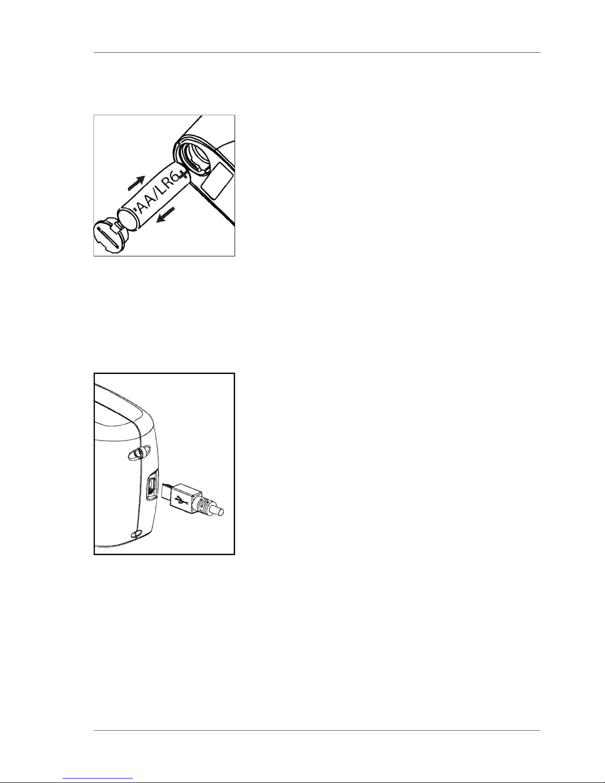
5.2 Changing the battery
To insert or change the battery open the battery
compartment. The easiest way to do this is by
turning the cover with a coin one-eighth of a rotation
to the left. Turn the device back around and allow
the old battery and the battery compartment cover
to slide into your hand.
Insert the new battery with the positive (top) end first
into the battery compartment and set the battery
compartment cover in place again. Lock the cover
by turning it one-eighth of a rotation to the right.
5.3 External power supply
The instrument can be operated and supplied at a
computer via USB-port. For the connection to the
PC use the USB- cable included in the delivery.
Please refer to the chapter Interface for installation
of the required software and drivers.
For power supply specification note the technical
data.
Changing the battery
16
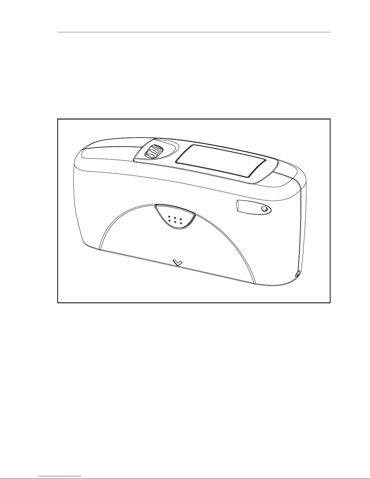
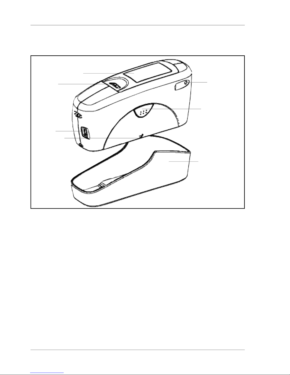
Controls
Measurement unit and protective holder
1 Mode scroll wheel: used to turn the unit on and for menu selection
2 Display for user guidance and displaying measurement values
3 Signal lamp:
green: measurement active
red: error
4 Operate button: used to activate measurements
5 Protective holder with integrated calibration standard
6 Mark for the measurement aperture
7 USB interface for connecting to a PC
1
2
4
3
6
7
5
6. Controls
 Loading...