

Page 1

Table of Contents
What is an ENERGY STAR@‚ Printer? ..........................................F-1
Safety Information...........................................................................F-2
CE Marking (Declaration of Conformity) .........................................F-5
Welcome.........................................................................................F-7
Trademark Acknowledgments.........................................................F-7
1 Quick Guide PagePro 18N
1.1 STEP 1: Unpacking the Printer....................................................1-1
1.2 Reference 1: Printer Parts............................................................1-3
1.3 Reference 2: Control Panel ..........................................................1-4
1.4 STEP 2: Attaching the Face-Down Tray and Tray 1...................1-5
1.5 STEP 3: Setting-up Tray 2............................................................1-7
1.6 STEP 4: Loading Paper...............................................................1-10
1.7 STEP 5: Connecting the Power Cord ........................................1-11
1.8 STEP 6: Turning the Power On/Off............................................1-12
Turning the power ON...................................................................1-12
Turning the power OFF.................................................................1-12
1.9 STEP 7: Printing a Configuration Page.....................................1-13
Sample..........................................................................................1-13
1.10 STEP 8: Connecting the Printer to the Computer
(Local Connection)......................................................................1-14
1.11 STEP 9: Installing the Printer Driver .........................................1-15
Windows 95/98/NT4.0 – Installing from the CD-ROM...................1-15
Windows 3.1 – Installing from the CD-ROM .................................1-16
MS-DOS – Installing DOS Printing Utilities...................................1-17
1.12 Reference 3: Troubleshooting...................................................1-18
Clearing a Paper Misfeed – Outside the Printer............................1-18
Clearing a Paper Misfeed – Inside the Printer ..............................1-19
Solving Print Quality Problems......................................................1-19
No output.......................................................................................1-19
PagePro 18N -1
Page 2

2 Introduction
2.1 Features.........................................................................................2-1
2.2 Printer Parts and Accessories .................................................... 2-2
2.3 Control Panel................................................................................ 2-4
Indicator Lights ...............................................................................2-4
Control Panel Button ......................................................................2-6
3 Setting-Up
3.1 Installation Precautions............................................................... 3-1
Selecting a Location for the Printer ................................................3-1
Power Source.................................................................................3-2
Grounding.......................................................................................3-2
Space Requirements......................................................................3-3
3.2 Operational Precautions..............................................................3-4
Operating Environment...................................................................3-4
Printer.............................................................................................3-4
Printer Supplies ..............................................................................3-6
3.3 Setting-up......................................................................................3-7
Installing the Face-Down Tray........................................................3-7
Installing Tray 1 ..............................................................................3-8
Second Paper Cassette Unit..........................................................3-9
Installing the Second Paper Cassette Unit.....................................3-9
Connecting the Power Cord .........................................................3-11
Loading Paper..............................................................................3-12
Turning On the Printer..................................................................3-14
Testing the Printer........................................................................3-15
Connecting to a Computer............................................................3-17
Network Interface Card (NIC).......................................................3-17
3.4 Options........................................................................................3-18
SIMM (Single In-line Memory Module).........................................3-18
Installing the Optional SIMM.........................................................3-19
Duplex Unit...................................................................................3-23
Installing the Duplex Unit..............................................................3-24
Printer Configuration.....................................................................3-25
Third Paper Cassette Unit............................................................3-26
Installing the Optional Third Paper Cassette Unit.........................3-26
Printer Configuration.....................................................................3-28
Adobe PostScript ROM-SIMM......................................................3-29
Installing the Optional Adobe PostScript ROM-SIMM ..................3-29
Printer Configuration.....................................................................3-33
-2 PagePro 18N
Page 3

4 Using the P rinter
4.1 Paper..............................................................................................4-1
Type................................................................................................4-1
Size.................................................................................................4-2
Envelopes and custom sizes (Tray 1 and Manual Feed Tray)........4-2
4.2 Loading Paper...............................................................................4-4
Loading Paper onto Tray 1..............................................................4-5
Loading Paper onto Tray 2/Tray 3 ..................................................4-7
Manual Paper Feed.......................................................................4-10
Printing on Envelopes...................................................................4-12
Duplex Printing..............................................................................4-14
5 Printer Driver
5.1 System Requirements ..................................................................5-1
5.2 Installing the Printer Driver Under Windows 95/98....................5-2
To Install the Printer Driver from the CD-ROM ...............................5-2
To Uninstall the Printer Driver.........................................................5-5
5.3 Installing the Printer Driver Under Windows NT 4.0..................5-7
To Install the Printer Driver from the CD-ROM ...............................5-7
To Uninstall the Printer Driver.......................................................5-12
5.4 Installing the Printer Driver Under Windows 3.1......................5-14
Install the Printer Driver.................................................................5-14
To Uninstall the Printer Driver.......................................................5-16
5.5 Displaying the Driver Setup Dialog
(Windows 95/98/NT 4.0)5-18
To Display the Driver Setup Dialog Under Windows 95/98...........5-18
To Display the Driver Setup Dialog Under Windows NT 4.0.........5-20
5.6 Using the Printer Driver Under
Windows 95/98/NT 4.05-22
Paper.............................................................................................5-23
Page Layout..................................................................................5-28
To Add a Watermark.....................................................................5-30
To Remove a Watermark from the List .........................................5-31
To Edit a Watermark.....................................................................5-31
Quality...........................................................................................5-32
Detail of Quality.............................................................................5-34
Device Option................................................................................5-35
About.............................................................................................5-35
5.7 Displaying the Driver Setup Dialog (Windows 3.1)..................5-36
PagePro 18N -3
Page 4

5.8 Using the Printer Driver Under Windows 3.1...........................5-37
Settings.........................................................................................5-38
Options.........................................................................................5-40
5.9 DOS Printing Utilities.................................................................5-42
Installing the Printer Driver Under DOS........................................5-42
Loading and Unloading the Status Display ...................................5-42
To Load the Status Display From the DOS Prompt......................5-43
To Remove the Status Display From Memory..............................5-43
5.10 Accessing the Printer Control Panel ........................................5-44
To Access the Printer Control Panel ............................................5-44
To Exit the Printer Control Panel..................................................5-44
5.11 Using the Printer Control Panel................................................5-45
Getting Around in the Printer Control Panel.................................5-45
To Print a Test Page or Demo Page ............................................5-45
To Register Installed Options.......................................................5-45
Printer Control Panel Screens......................................................5-46
Paper Screen................................................................................5-46
Font Selection Screen..................................................................5-48
Output Quality Screen ..................................................................5-49
Counter Screen ............................................................................5-50
Configuration Screen....................................................................5-51
Printer Setting Screen ..................................................................5-52
5.12 Using the Status Display ...........................................................5-53
To Display the Status Display.......................................................5-53
Status Display Screen .................................................................. 5-54
6 Printer Status Display and Control Panel
6.1 Using the Printer Status Display.................................................6-1
Opening the Printer Status Display ................................................6-1
Using the Printer Status Display.....................................................6-2
Switching Between the Expanded and Reduced Views.................6-2
On-line Help....................................................................................6-2
6.2 Using the Control Panel...............................................................6-3
Paper..............................................................................................6-4
Printer Setting.................................................................................6-6
Test Print ........................................................................................6-7
Counter...........................................................................................6-8
Configuration..................................................................................6-9
-4 PagePro 18N
Page 5

7 Maintenance
7.1 Replacing the Imaging Cartridge.................................................7-1
To Replace the Imaging Cartridge..................................................7-2
7.2 Cleaning the Printer......................................................................7-5
Cleaning the Outside of the Printer.................................................7-5
Cleaning the Paper Transport Roller...............................................7-6
8 Troubleshooting
8.1 Clearing a Paper Misfeed.............................................................8-1
Inside the Printer.............................................................................8-1
Paper Output Misfeed.....................................................................8-4
Paper Input Misfeed (from Tray 1)..................................................8-4
Paper Input Misfeed (from Manual Feed Tray)...............................8-4
Paper Input Misfeed (from Second/Third Paper Cassette Unit) ......8-5
Paper Misfeed in the Duplex Unit....................................................8-6
8.2 Print Quality Problems .................................................................8-7
Blank pages ....................................................................................8-7
Black pages.....................................................................................8-7
Printout too light ..............................................................................8-8
Printout too dark..............................................................................8-8
Blurred background.........................................................................8-8
Uneven print density .......................................................................8-9
Irregularities....................................................................................8-9
White or black line...........................................................................8-9
Toner smudges.............................................................................8-10
No output.......................................................................................8-10
9 Specifications
9.1 PagePro 18N Printer .....................................................................9-1
9.2 Second Paper Cassette Unit ........................................................9-2
9.3 Third Paper Cassette Unit (Option).............................................9-3
9.4 Duplex Unit (Option).....................................................................9-3
9.5 Interface Connector and Cable....................................................9-4
9.6 SIMM (Option)................................................................................9-4
10 General Information
10.1 END USER LICENSE AGREEMENT................................................5
10.2 Contrat utilisateur de la licence......................................................8
10.3 ENDVERBRAUCHER-LIZENZVERTRAG......................................11
PagePro 18N -5
Page 6

10.4 CONTRATTO DI LICENZA D’USO ................................................ 14
10.5 Addresses MINOLTA-Partners in Europe ................................... 17
10.6 MINOLTA GUARANTEE CERTIFICATE........................................ 20
11 Glossary
12 Index
-6 PagePro 18N
Page 7
As an ENERGY STAR‚ Partner, we
have determined that this machine
meets the ENERGY STAR‚ Guidelines
for energy efficiency.
What is an ENERGY STAR@‚Printer?
ENERGYSTAR‚printers have a featurethatallows them to automatically
“go to sleep” after a period of inactivity. This auto-feature can reduce a
machine’s annual electricity cost by 60 percent.
PagePro 18N F-1
Page 8

Safety Information
l Laser Safety
This is a pageprinterwhich operates by means of a laser.Thereisno
possibility of danger from the laser, provided the printer is operated
according to the instructions in this manual.
Since radiation emitted by the laser is completely confined within
protective housing, the laser beam cannot escape from the machine
during any phase of user operation.
l Internal Laser Radiation
Maximum Radiation Power: 1.03 (mW) at laser aperture of the print
head unit
Wavelength: 770-810 (nm)
This product employs Class IIIb Laser Diode.
LaserDiodeand ScanningPolygonMirrorareincorporatedintheprint
head unit.
The print head unit is NOT A FIELD SERVICE ITEM.
Therefore, the print head unit should not be opened under any
circumstance.
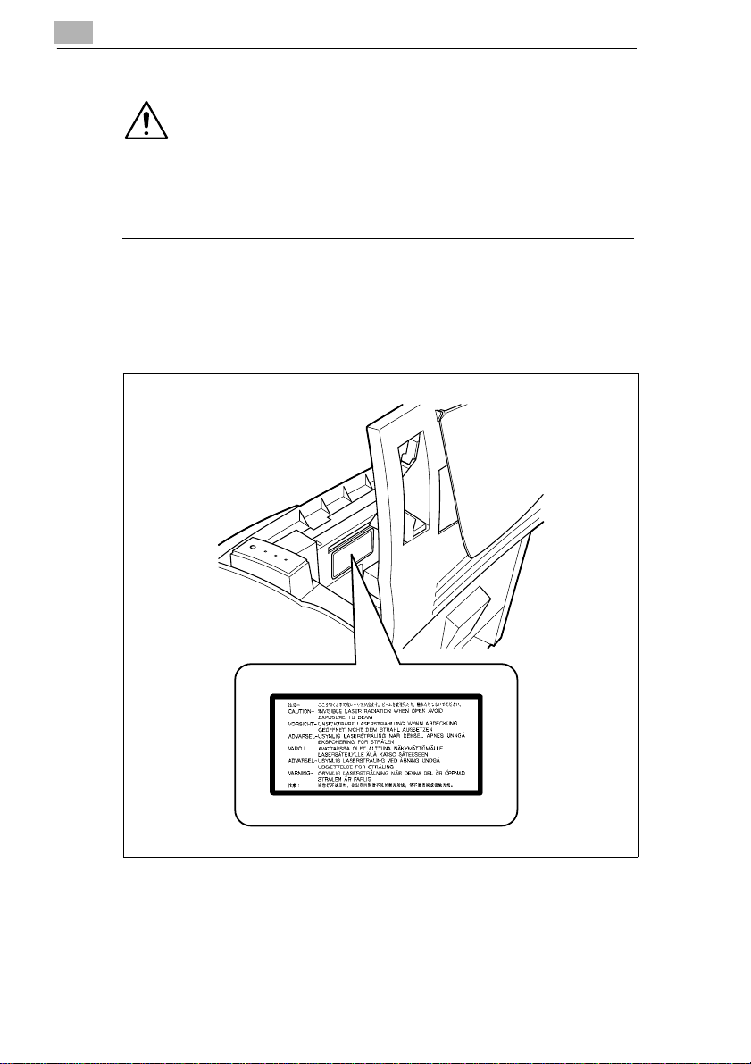
l Laser Safety
This printer is certified as a Class 1 Laser product under the U.S.
Department of Health and Human Services (DHHS) Radiation
Performance Standard according to the Radiation Control for Health
and Safety Act of 1968. This means that the printer does not produce
hazardous laser radiation.
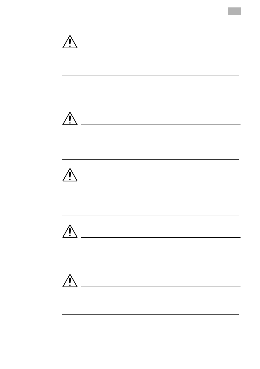
l CDRH Regulations
The Center for Devices and Radiological Health (CDRH) of the U.S.
Food and Drug Administration implementedregulationsfor laser
products on August 2, 1976. Compliance is mandatory for products
marketed in theUnitedStates.The label shown on the following page
indicates compliance with the CDRH regulations and must be
attached to laser products marketed in the United States.
WARNING
è Useofcontrols,adjustments orperformanceof proceduresotherthan
those specified in this manual may result in hazardous radiation
exposure.
This is a semiconductor laser. The maximumpower of the laserdiode
is 5mW and the wavelength is 770-810 nm.
F-2 PagePro 18N
Page 9
For Denmark Users
ADVARSEL
è Usynlig laserstråling ved åbning, når sikkerhedsafbrydere er ude af
funktion. Undgå udsættelse for stråling.
Klasse 1 laser produkt der opfylder IEC825 sikkerhedskravene.
For Finland, Sweden Users
VAROITUS
è Laitteen käyttäminen muulla kuin tässä käyttöohjeessa mainitulla
tavalla saattaa altistaa käyttäjän turvallisuusluokan 1 ylittävälle
näkymättömälle lasersäteiylle.
VARNNING
è Om apparaten används på annat sätt än i denna bruksanvisning
specificerats, kan användaren utsattas for osynlig laserstrålning som
överskrider gränsen för laser klass 1.
VARO
è Avattaessa ja suojalukitus ohitettaessa olet alttiina näkymättömälle
lasersäteilylle. Äjä katso säteeseen.
VARNING
è Osynlig laserstråining när denna del är öppnad och spärren är
urkopplad. Betrakta ej stråien.
PagePro 18N F-3
Page 10
For Norway Users
ADVARSEL
è Dersom apparatet brukes på annen måte enn spesifisert i denne
bruksanvisning, kan brukeren utsettes for unsynlig laserstråling som
overskrider grensen for laser klasse 1.
Dette er en halvlederlaser.Maksimaleffeckt til laserdiode er 5mW og
bølgelengde er 770-810 nm.
WARNING LABEL
F-4 PagePro 18N
Page 11

CE Marking (Declaration of Conformity)
We declare under our sole responsibility that the printer and option to
which this declaration relates is in conformity with the specifications
below.
This declaration is valid for the area of the European Union (EU) only.
ProductType LaserBeam Printer
ProductName PagePro18N
Options
Accessories
Standard Safety:
EC Directive Safety: 73/23/EECand 93/68/EEC
Third Paper Cassette Unit (4166)
DuplexUnit (4168)
DRAM SIMM (Maximum 64MB)
Adobe PostScript SIMM (4179-292)
EN60 950/1992 (A1,A2, A3, A4,A11):
:Safetyof information technology equipment, including
electrical business equipment
EN60825-1/1994(A11)
:Radiation safety oflaser products, equipment classification,
requirements and user’s guide
EMC:
EN55 022(Class B)/1994 (A,A2)
:Limits and method for measurement of radio disturbance
characteristicof information technology equipment(ITE)
EN61000-3-2(Class A)/1995
:Limits for harmonic currents e missio ns
EN61000-3-3/1995
:Limitationof voltage fluctuations andflicker in low-voltage
supply systems.
EN50 082-1/1997
Genericimmunity standard
Part1: Residential, commercialand light industry
EN61000-4-2
:Electrostatic discharge immunity test
EN61000-4-3/1996,ENV50204/1995
:Radiated radio-frequency electromagnetic field immunitytest
EN61000-4-4/1995
:Electrical fasttransient/burst immunity test
EN61000-4-5/1995
:Surge immunity test
EN61000-4-6/1996
:Conducted disturbances induced byradio-frequency
electromagneticfield immunity test
EN61000-4-8/1993
:Power-frequency magnetic field immunity test
EN61000-4-11/1994
:Voltage dips, short interruption and voltage variations
immunity test
Notes:
1.EMC performance:This product was designed for operation
in atypical office environment.
2. First yearof labeling according to EC-directive 73/23/EEC
and 93/68/EEC : 98
EMC: 89/336/EEC and93/68/EEC
This device must be used with a shielded interface cable and shielded
network (10/100BaseT) cable. The use of non-shield cables is likely to
PagePro 18N F-5
Page 12
result in interference with radio communications and is prohibited under
89/336/EEC rules.
OZONE RELEASE (For All Users)
During printer operation, a small quantity of ozone is released. This
amountis notlargeenoughto harm anyone adversely. However, be sure
the room where the machine is being used has adequate ventilation,
especially if you are printing a high volume of materials, or if the machine
is being used continuously over a long period.
WARNING LABEL
F-6 PagePro 18N
Page 13

Welcome
AndthankyouforselectingaMinoltaPagePro18NPrinter!
This
User’s Manual
operates.Italsoprovides you with troubleshootingtipsas wellasgeneral
precautionsyou shouldobservewhenoperatingtheprinter.Toensure the
top performance and effective use of your printer, read this manual
carefully from cover to cover, and keep it at hand for later reference.
No part of this document may be reproduced, transmitted, transcribed,
storedinaretrievalsystem, or translated intootherlanguages without the
express written prior consent of Minolta Co., Ltd.
The contents of this manual are subject to change without notice.
Trademark Acknowledgments
PCL is a registered trademark of Hewlett-Packard Company.
Centronics is a registered trademark of Centronics Inc.
MS-DOS, Microsoft, Windows, and Windows NT are registered
trademarks of Microsoft Corporation.
IBM is a registered trademark of International Business Machines
Corporation.
Adobe and PostScript are registered trademarks of Adobe Systems, Inc.
PagePro is a trademark of Minolta in Europe, Japan and Asia.
Fine-ART and Fine Micro Toning are trademarks of Minolta Co., Ltd.
Allother brandorproduct namesare trademarksor registeredtrademarks
of their respective companies or organizations.
explains the functions of the printer and how it
PagePro 18N F-7
Page 14

F-8 PagePro 18N
Page 15
Quick Guide PagePro 18N
1 Quick Guide Pa gePro 18N
1.1 STEP 1: Unpacking the Printer
Before operating your printer, read the Set-Up Instructions carefully from
cover to cover. Use this guide for reference
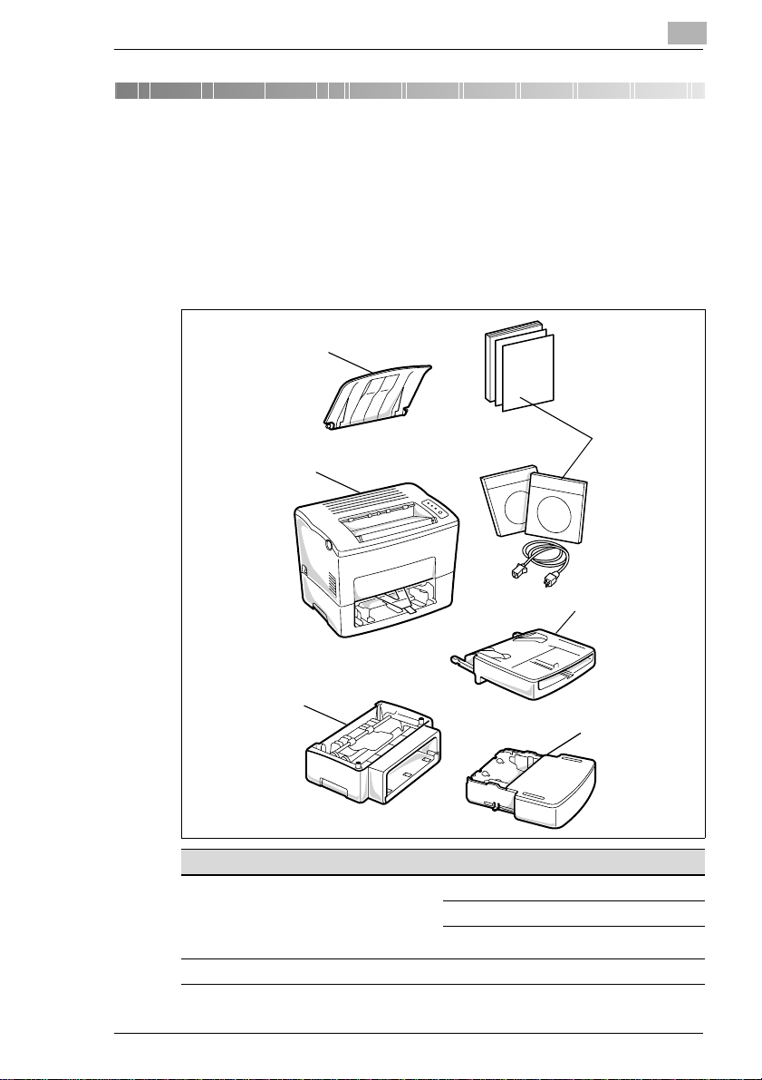
1 Take the items and accessories shown below out of the carton.
6
5
1
1
2
4
3
Pos. Name Pos. Name
1 Accessories
l UserKit including
CD-ROM
l QuickGuice for NIC
l Power cord
2 Tray 1 6 Face-downtray
3Tray2
4 Secondpaper cassette unit
5 Printer
PagePro 18N 1-1
Page 16
1
Quick Guide PagePro 18N
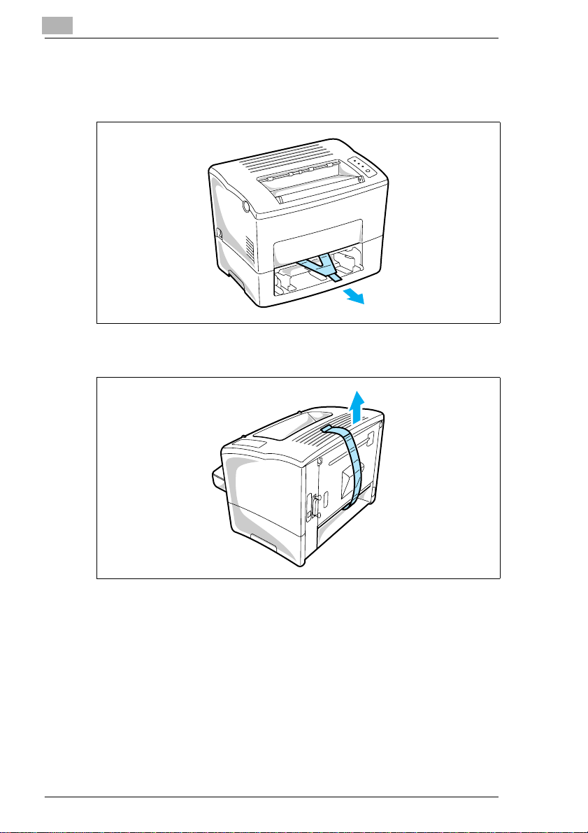
2 Remove theplasticbagand peel off the shippingtapefrom the printer.
3 Pull out the plastic-lead strip from the paper feed inlet.
4 Remove the tape strip from the back of the printer.
1-2 PagePro 18N
Page 17
Quick Guide PagePro 18N
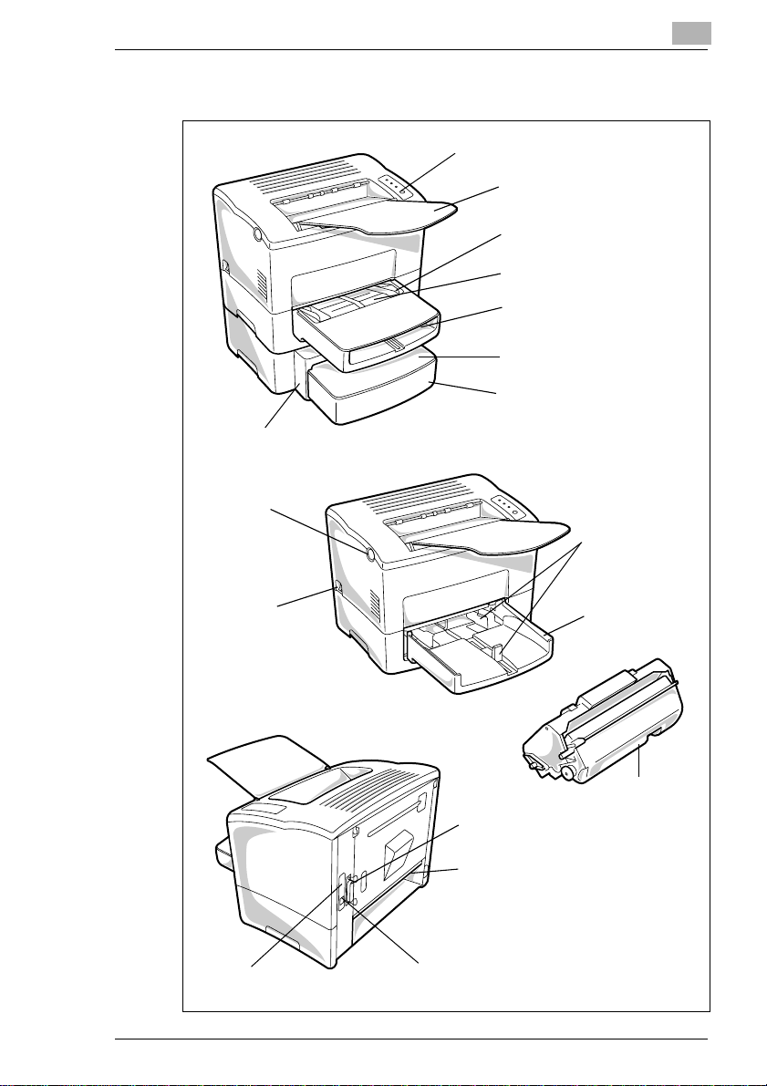
1.2 Reference 1: Printer Parts
Second paper
cassette unit
Top cover release
button
1
Control panel
Face-down tray
Paper size guide
Manual feed tray
Tray cover
Cassettecover
Tray 2
(500-sheets econd cassette)
Paper size guide
Tray 1
Power switch
Network interface
card (NIC)
Parallel interface
connector
Power cord socket
Ethernet interface
connector (10/100BaseT)
(multipurpose tray)
Imaging
cartridge
PagePro 18N 1-3
Page 18
1
1.3 Reference 2: Control Panel
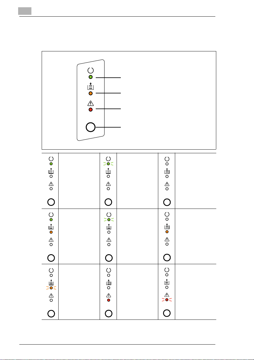
The control panel has three indicator lights and one button
READY indicator(green)
PAPER indicator (amber)
ERROR indicator (red)
Panel button
Quick Guide PagePro 18N
Printer is ready. Receiving data via
The printer is
waitingfor paperto
be loaded
manually.
Paper misfeed.
Clear the paper
misfeedtocontinue
printing.
parallel interface;
printing in progress.
(Slow blinking)
Powersave mode.
Cover open. Close
the cover.
Power is off.
Out ofpaper. Load
more paper to
continue printing.
Memory overflow/
data received
cannotbe
processedbecause
it istoo complex.
1-4 PagePro 18N
Page 19
Quick Guide PagePro 18N
1.4 STEP 2: Attaching the Face-Down Tray and Tray 1
1
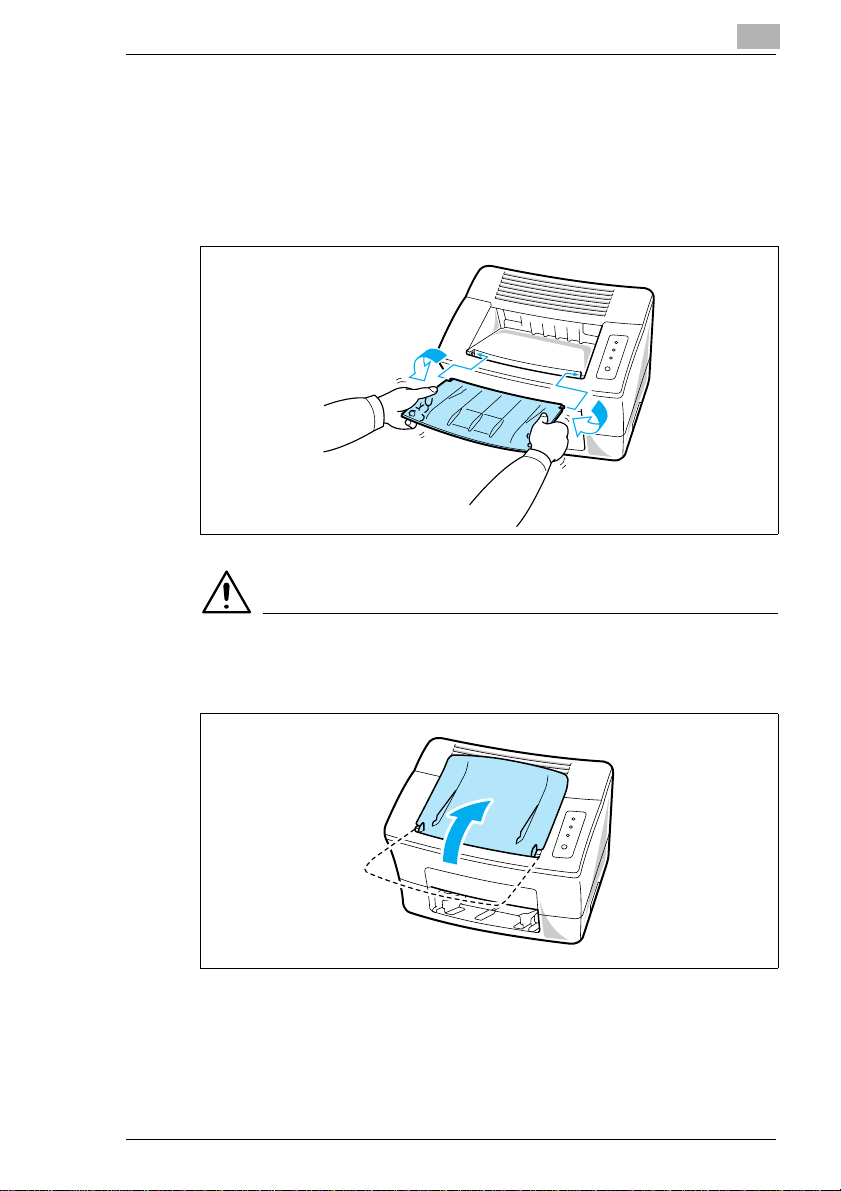
With both hands, gently bend the face-down tray inwards and insert
one of its tabs into its holder on the upper portion of the printer.
Continue to bend the face-down tray so that it curves enough for the
second tab to fit into its holder and release the tray into position.
1
NOTE
è Be sure to close the face-down tray before opening the top cover to
prevent injuries.
PagePro 18N 1-5
Page 20
1
Quick Guide PagePro 18N
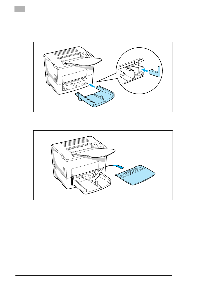
2 Using the left and right slots in the printer as guides, gently push
Tray 1 until it cannot be inserted any further (as shown in the
illustration).
3 Attach the tray cover onto Tray 1.
1-6 PagePro 18N
Page 21
Quick Guide PagePro 18N
1.5 STEP 3: S etting-up Tray 2
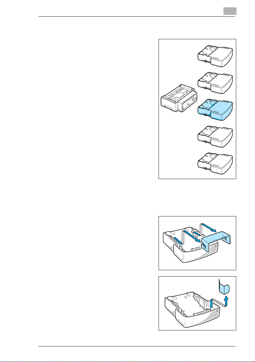
The second paper cassette unit comes
with a cassette that can hold up to 500
sheets of A4 size paper called Tray 2.
The same unit can accommodate a
variety of other papertraysaswell(JIS
B5, Letter, Legal and Executive).
Contact yourdealer to find outhowyou
can add these trays to increase the
capabilities of your printer.
1
JIS B5
Letter
A4
Legal
Exective
1 Remove the second paper cassette unit and Tray 2 from their
packaging, including the protective tape used to hold the various
components in place.
2 Remove the protective cardboard
packaging from the cassette as
shown in the illustration below.
3 Remove the remaining tape and
packaging as shown.
PagePro 18N 1-7
Page 22
1
Quick Guide PagePro 18N
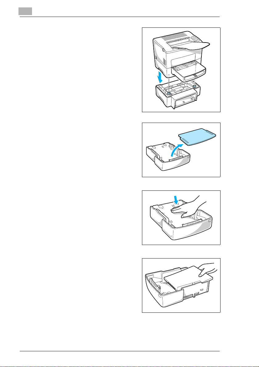
4 Place the printer on top of the base
unit.Makesure toalign thecoupling
pins of the base unit with the holes
located underneath the printer.
5 Remove the cassette cover from
Tray 2.
6 Press down on the paper lifting
plate located inside of Tray 2 until it
locks.
7 Place a stack of up to 500 sheets of
paper into Tray 2 so that the side
that was facing up when the paper
was unwrapped is still facing up.
1-8 PagePro 18N
Page 23
Quick Guide PagePro 18N
8 Replace the cassette cover and
insert Tray 2 into the second paper
cassette unit.
NOTE
è Be sure to use both hands whenever Tray 2 is being removedfromor
inserted into the second paper cassette unit.
1
è The cassette is designed to remain in the unit during the normal
loading and operation of the printer. To remove Tray 2 from the unit,
pull it out as far as it will go without force. Then gently raise the
forward-end up.
PagePro 18N 1-9
Page 24
1
1.6 STEP 4: Loading Paper
1
Remove the tray cover from Tray 1.
2 Open all three paper size guides.
3 Place the paperstack ontothetray,
print-side up. Secure the stack by
adjusting the paper size guides.
Quick Guide PagePro 18N
4 Replace the tray cover onto
Tray 1.
1-10 PagePro 18N
Page 25
Quick Guide PagePro 18N
1.7 STEP 5: Connecting the Power Cord
1
Make sure that the printer’s power
switch is in the O (Off) position.
2 Connect one end of the power cord
that comes with the printer to the
power cord socket. Plug the other
end into a power outlet.
1
PagePro 18N 1-11
Page 26
1
Quick Guide PagePro 18N
1.8 STEP 6: Turning the Power On/Off
Turningthe power ON
After connecting the printer to a power
outlet, press the power switch to the I
(On) position.
Turning on the printer causes all the
indicators on the control panel to light,
which indicates that the printer is
warming up. In about 23 seconds only
the READY indicator remains lit,
indicating that the printer is ready to
print.
Turningthe power OFF
Press the power switch to the O (Off) position to turn the printer off.
NOTE
DO NOT turn the power OFF while:
è printing
è theprinteris receivingthe data fromthecomputer (theindicatoronthe
control panel is blinking)
1-12 PagePro 18N
Page 27
Quick Guide PagePro 18N
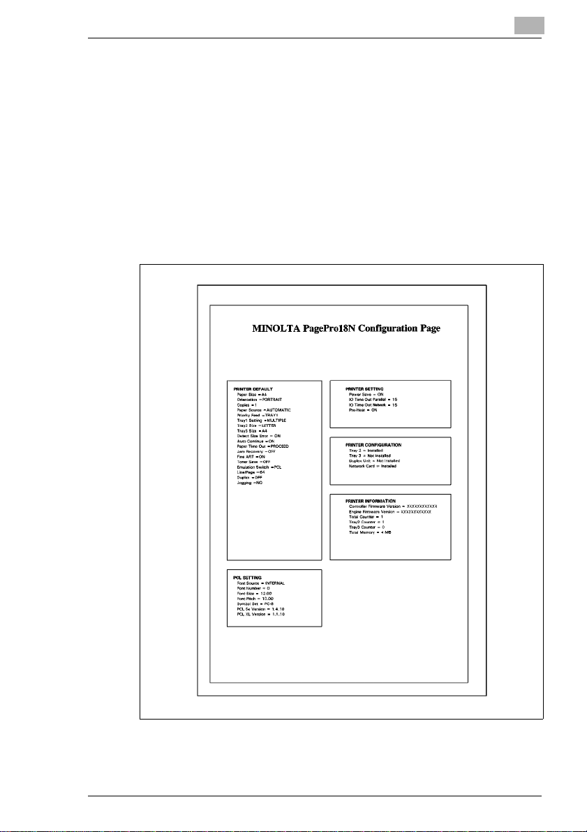
1.9 STEP 7: Printing a Configuration Page
1
Turn the printer on.
2 Make sure that paper is loaded into the printer’s feeding tray.
3 Make sure that both the Paper and Error indicators are off, and the
Ready indicator is on.
4 Briefly press the panel button to start printing the Configuration Page.
Sample
1
PagePro 18N 1-13
Page 28
1
Quick Guide PagePro 18N
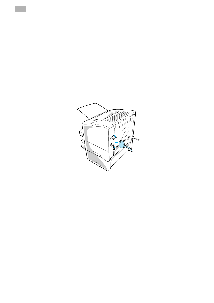
1.10 STEP 8: Connecting the Printer to the Computer (Local Connection)
1
Make sure that the printer and the computer you are connecting it to
are both turned off.
2 Connect one end of the interface cable to the parallel port of the
computer.
3 Connect the other end of the cable to the parallel connector on the
back oftheprinter.Securethe cable usingthetwoclips on the parallel
connector.
1-14 PagePro 18N
Page 29
Quick Guide PagePro 18N
1.11 STEP 9: Installing the Printer Driver
Install the printer driver to control the printer from your computer.
You can install the printer driver for Windows 95, Windows 98, Windows
NT 4.0, Windows 3.1 or MS-DOS from the Printer Driver CD-ROM.
Followtheinstructionsbelow and for moredetails,see the User’s Manual
that came with your printer.
Windows 95/98/NT4.0 – Installing from the CD-ROM
1 Turn on your computer and start up Windows 95, Windows 98 or
Windows NT 4.0.
2 InsertthePrinterDriver CD-ROMintoyour computer’s CD-ROMdrive.
In this example, we will assume that D: is the name of the CD-ROM
drive.
3 Open the Windows Explorer, browse to the CD-ROM drive and
navigate to: D:\DRIVER\WIN95NT\GB
4 Double-click Setup.exe.
1
NOTE
è The printer driver must be installed using the CD-ROM’s Setup.exe.
Do not use the Add Printer wizard from the Printers folder. Installation
through the AddPrinterwizardwillpreventtheprinterfromperforming
properly.
After installing the printer driver, the Minolta PageWorks/Pro 18 printer
icon appears in the Printers folder.
PagePro 18N 1-15
Page 30

1
Quick Guide PagePro 18N
Windows 3.1 – Installing from the CD-ROM
1 Turn on your computer and start up Windows 3.1.
2 InsertthePrinter DriverCD-ROMintoyour computer’sCD-ROMdrive.
In this example, we will assume that D: is the name of the CD-ROM
drive.
3 Double-clicktheControlPaneliconwhich is locatedintheMain group
within the Program Manager.
4 In the Control Panel dialog, double-click [Printers] to display the
Printersdialogbox and then click the [Add>>] buttontodisplay the list
of printers.
5 Select Install Unlisted or Updated Printer and click the [Install...]
button.
6 In the Install Driver dialog box, click the [Browse...] button.
7 Browse to the CD-ROM drive and navigate to:
D:\DRIVER\WIN311\GB
8 Click [OK] in the Install Driver dialog box.
9 From the List of Printers box, select Minolta PageWorks/Pro 18, and
then click[OK]to start installationand return to thePrintersdialog box.
NOTE
è An error message may appear during installation of the printer driver
informing you that a required UNIDRV.DLL file cannot be found.
Should this occur, install a UniTool Driver such as HP LaserJet from
the List of Printers box in the Printers dialog. After installing the
UniTool Driver, reinstall the driver for the PageWorks/Pro 18.
10 Click the [Set As Default Printer] button so that this printer is selected
whenever you begin using your Windows software.
11 Click [Close] to finish the installation procedure.
1-16 PagePro 18N
Page 31

Quick Guide PagePro 18N
MS-DOS – Installing DOS Printing Utilities
1 Connect your printer to the parallel port of your computer.
2 Turn on your computer and start up DOS.
3 Turn on your printer and make sure it is online.
4 InsertthePrinterDriverCD-ROMintoyour computer’sCD-ROMdrive.
In this example, we will assume that D: is the name of the CD-ROM
drive.
5 Enter the name that has been designated to your CD-ROM drive. For
example, if your CD-ROM is designated as “drive D”, enter:
C:\>D:
6 Specify the directory under which the DOS printing utility is located:
D:\>CD DRIVER\DOSUTLTY\GB
7 Type install and press the [Enter] key.
D:\DRIVER\DOSUTLTY\GB:\>INSTALL
8 The installer will automatically execute and the following message will
be displayed:
SETUP WILL INSTALL DOS UTILITY IN THE FOLLOWING DIRECTORY.
C:\PP18
1. TO INSTALL TO THIS DIRECTORY.
2. TO INSTALL TO A DIFFERENT DIRECTORY.
3. EXIT SETUP.
ENTER A CHOICE : 1
Select item 1 under Enter a choice to install the utility into the
recommended directory or item 2 to install it into a different directory.
1
PagePro 18N 1-17
Page 32

1
1.12 Reference 3: Troubleshooting
Clearing a Paper Misfeed – Outside the Printer
Remove the misfed sheet of paper by pulling it in the direction indicated
by the arrow.
Face-down tray
Quick Guide PagePro 18N
Tray 1
Tray 2
Manual feed tray
1-18 PagePro 18N
Page 33

Quick Guide PagePro 18N
Clearing a Paper Misfeed – Inside the Printer
CAUTION
è The fusing unit inside the printer can become very hot during
operation. Do not touch the area to avoid injury.
è Do not touch the image transfer roller.
1
Solving Print Quality Problems
l Remove the imaging cartridge and gently shake it a few times to
distribute remaining toner.
l Remove the imaging cartridge and check it for damage. Replace the
imaging cartridge with a new one if necessary.
l Clean the inside of the printer. (Refer to the User’s Manual.)
l Change the toner save setting of the printer driver and try to print
again.
For more details, refer to the “Troubleshooting” and “Maintenance”
sections of the User’s Manual.
No output
l Make sure that the printer is plugged in.
l Make sure that power is turned on.
l Make sure that you are using the correct type of printer cable.
l Make sure that your computer’s communication port settings are
correct.
For more details, refer to the User’s Manual.
PagePro 18N 1-19
Page 34

1
Quick Guide PagePro 18N
1-20 PagePro 18N
Page 35

Introduction
2Introduction
2.1 Features
The Minolta PagePro 18N is a laser printer developedexclusivelyforuse
with Windows 95, Windows 98, Windows NT 4.0, Windows 3.1 and DOS
operating systems.
The various features listed below make the Minolta PagePro 18N the
perfect printer for any size office.
l Fast 18-page per minute printing speed
l PCL 6 support for faster, more precise printing
l Large 750-sheet paper capacity
l 10/100BaseT Ethernet network interface card
l Automatic "jogger" print-job separator
l Powerful 66 MHz Power PC and QuickPrint dual processors
l 4MBofmemory
l Expanded digital-documentationsupportthrough an optional Adobe
PostScript 3 SIMM
l PageScope Web-based printer utilities for simplified network printer
management
2
PagePro 18N 2-1
Page 36

2
2.2 Printer Parts and Accessories
Introduction
Control panel
Face-down tray
Manual feed tray
Paper size guide
Tray cover
Cassettecover(option)
Tray 2 (500-sheet
second cassette)
(option)
Cassettecover
(option)
Second paper
cassetteunit
(option)
Top cover release button
Power
switch
Third paper
cassette unit(option)
Tray 3 (500-sheet
third cassette)
(option)
Paper size guide
Tray 1
(multipurpose tray)
2-2 PagePro 18N
Page 37

Introduction
2
Power cord socket
Parallel interface
connector
Network Interface
Card (NIC)
Ethernet interface
connector
(10/100BaseT)
Top cover
Fusing unit
Image transferroller
Imaging cartridge
PagePro 18N 2-3
Page 38

2
2.3 Control Panel
The control panel has three indicator lights and one button.
IndicatorLights
The three indicator lights turn on, off, or blink in combination to let
youknow the current status of the printer. You can find o ut details of the
printer’sstatus bychecking theinformation thatappears onyour computer
screen through the Status Monitor.
Introduction
Ready (green)
Paper (amber)
Error (red)
Panel button
IndicatorLights Printer Status and Recommended Action
Ready
(green)
On Off Off Printer is ready.
Off Off Off Power is off.
Blinking Off Off Receivingdata via parallel interface;printing in progress.
Blinking Off On Receivingdata via network interface.
Blinking Blinking Blinking Ca nceling job.
Blinking Blinking Off Warmingup.
On On On “Power on” initialsetting.
Slow
Blinking
Off On Off Out of paper.
On Off On The imaging cartridge is low on toner.
Paper
(amber)
Off Off Power save mode.
Error
(red)
Turn on the printer.
Load more paper to continue printing.
Ready a new imaging cartridge, see page 7-1.
2-4 PagePro 18N
Page 39

Introduction
IndicatorLights Printer Status and Recommended Action
Ready
(green)
On Blinking On The imagingcartridge is out of toner.
Off Blinking On Data iscurrently being compressed because more data is
Off Off Blinking Memory overflow/datareceived cannot beprocessed
Off Blinking Blinking The wrong size or multiplesheets of paper were fed into
On Blinking Off The printer iswaiting forpaper to be loaded.
On On Off The printer is waiting for paper to beloaded manually.
Off Off On Cover is open.
Off Blinking Off Paper misfeed.
On Blinking Blinking 1. The second or third paper cassette unit is notinstalled.
Off On Blinking Controller-memory error.
Off On On Engine error (jogging function).
On Off Blinking Engine error (fusing unit).
Paper
(amber)
Error
(red)
Replace the imagingcartridge, see page 7-1.
being processed thancan be managed by the amount of
memory installedin your printer. You may noticea
difference in image quality when compressed data is
printed.
Installation of additionalmemory willhelp to prevent data
from being compressed.
because it is too complex.
Install an optionalexpansion memorySIMM intothe printer
or decrease theamount ofdata being sent tothe printer.
the printer.
Load the appropriatesize ofpaper ontothe specifiedtray.
Press thebutton toresume printing.
Load theappropriatesize of paper ontoone of thetrays.
Load theappropriatesize of paper ontothe manualfeed
tray and press the panel button.
Close the cover.
Clear the paper misfeed tocontinue printing.
2. The NIC is not ready.
1. Press and hold the panelbutton.
2. If thismessage persists for anextendedperiod,the NIC
may be damaged or disabled.Contact your dealer.
Turn offthe printer andcontact yourdealer.
Turn theprinter off andon again. Ifthe problempersists,
contactyour dealer.
Turn offthe printer andcontact yourdealer immediately.
2
PagePro 18N 2-5
Page 40

2
Introduction
IndicatorLights Printer Status and Recommended Action
Ready
(green)
On On Blinking Engine error (laser).
Blinking Off Blinking Engine error (polygon scanner).
Blinking On Blinking Engine error (fan motor).
Blinking Blinking On Energie error (HSYNC)
Paper
(amber)
Error
(red)
Turn theprinter off and on again. If the problempersists,
contact your dealer.
Turn theprinter off and on again. If the problempersists,
contact your dealer.
Turn theprinter off and on again. If the problempersists,
contact your dealer.
Turn offthe printerand contact yourdealer.
Control Panel Button
Dependingon the status oftheprinter,the [controlpanel]buttonperforms
any one of the following operations.
l Job cancel
Use the following procedurewhenever you want to cancel the current
job.
Hold down the [control panel] button for about five seconds.
Afterallthe indicatorlightsare lit,releasethe [controlpanel]button
to cancel the print job.
l Print configuration page
Use the following procedure whenever you want to print a sheet that
shows the current printer settings.
Briefly press the [control panel] button to start printing the
configuration page.
l Form feed
When a memory overflow occurs, press the [control panel] button to
perform a form feed.
2-6 PagePro 18N
Page 41

Setting-Up
3 Setting-Up
3.1 Installation Precautions
Note thefollowingimportant precautionswhenselecting a locationforthe
printer and when connecting it to a power source.
Selecting a Location for the Printer
A proper location helps to ensure that your printer provides you with the
long service life for which it is designed. Double-check to make sure that
the location you select has the following characteristics.
l Choose a location that is well-ventilated.
l Make sure there is no chance of ammonia or other organic gases
being generated in the area.
l The power outlet you plan to connect to should be nearby and
unobstructed.
l Make sure that the printer is not exposed to direct sunlight.
l Avoid areas in the direct airflow of air conditioners, heaters, or
ventilators, and areas subjected to temperature and humidity
extremes.
l Choose asturdy,levelsurface where the printerwillnotbe exposed to
strong vibration.
l Keep the printerawayfrom any objects that might blockitsheatvents.
l Do not locate the printer near curtains or other combustible objects.
l Choose an area where there is no possibility of the printer being
splashed with water or other liquids.
l Make sure that the surrounding area is clean, dry, and free of dust.
3
PagePro 18N 3-1
Page 42

3
Setting-Up
Power Source
The following are the power source requirements for this printer.
l Power source: 220 - 240 V at 50 - 60 Hz
l Voltage fluctuation: Within 220 - 240 V ″10%
l Frequency fluctuation: Within ″0.3%
NOTES
è Use a power source with minimal voltage and frequency fluctuation.
è Only use an outlet that is rated for the voltage capacity specified for
this printer.
è Be sure to plug the power cord all the way into the outlet. The outlet
shouldbelocatednearthe printer andbeeasily accessiblesoyoucan
unplug the power cord immediately if necessary.
è Make sure the outlet you use is visible, and not hidden behind the
printer or any other object.
è If anyotherelectrical equipmentis plugged intothesame outlet, make
sure that the capacity of the outlet is not exceeded.
è If youusean extensioncord, make sureitscapacity isgreaterthanthe
power consumption of the printer. Using an extension cord with a
lower capacity creates the danger of fire.
è Never use a multiple socket to connect other appliancesor machines
to the same outlet being used to power the printer.
Grounding
Always groundtheprinterto guard against the danger of electricalshock.
To ground the printer, connect the grounding wire to the ground terminal
of the electrical outletyouareplugginginto or to a groundingcontactthat
complies with local electrical standards in your area.
NOTE
è Neverconnectthe groundingwire to agaspipe, the groundingwire for
a telephone, or to a water pipe.
3-2 PagePro 18N
Page 43

Setting-Up
3
Space Requirements
Be sure toprovidespace around the printerasindicated below,toensure
easier printer operation, paper and toner replacement,and maintenance.
" (300 mm)
11-3/4
29-1/2" (746 mm)
or more
** 34-1/4
** 46-1/2
" (867 mm)
or more
6" (150 mm)
or more
** 11-3/4"
(300 mm)
or more
"
40-1/2
(1,028 mm) or more
"
(1,178 mm) or more
or more
23-1/2
"
(600 mm)
or more
11-3/4
"
(300 mm)
or more
"
4
(100 mm)
or more
33
" (836 mm)
or more
* When equipped withan optionalsecond cassette unit.
** When equipped with an optional third cassetteunit.
PagePro 18N 3-3
Page 44

3
3.2 Operational Precautions
Note the following important precautions whenever using the printer.
Operating Environment
The following describes the operating environment required when using
the printer.
l Temperature: 10°C to 35°C (50°F to 95°F) with fluctuation of 10°C
(18°F) per hour
l Humidity: 15% to 85% with fluctuation of 20% per hour
Printer
The following describes precautions for using the printer.
l Never turn the printer off or open any of its covers during a print
operation.
l Never place flammable gasses, liquids or objects that generate
magnetic forces near the printer.
l When unplugging the power cord, always grasp the plug and never
pull on the cord. A damaged cord creates the danger of fire or
electrical shock.
l Never touch the power cord when your hands are wet. Doing so
creates the danger of electrical shock.
l Always unplugthepower cord before movingtheprinter.Failure to do
so candamagethe powercord,creating the dangeroffire or electrical
shock.
l Always unplug the power cord if you do not plan to use the printer for
a long time.
l Never try to remove any secured panel or cover. The interiorof the
printer contains high-voltage circuitry which creates the danger of
electrical shock when exposed.
l Never try to modify the printer. Doing so creates the danger of fire or
electrical shock.
l Never place anyheavyobjectson the power cord, pull on it or bend it.
Doing so creates the danger of fire or electrical shock.
l Always makesurethe printer isnotplaced on the electricalcord or the
communications cables of any other electrical equipment.Also make
sure that cords and cables do not get into the printer’s mechanism.
Any of these conditions create the danger of malfunction and fire.
Setting-Up
3-4 PagePro 18N
Page 45

Setting-Up
3
l Always take care so that paper clips, staples, or other small pieces of
metal do not get into the printer through its vents or other openings.
Such objects create the danger of fire or electrical shock.
l Do not allow water or other liquids to spill on or near the printer. Fire
or electrical shock can occur should water or liquid come into contact
with the printer.
l Should liquid or any piece of metal accidently get inside the printer,
immediatelyturn itoff, unplugthepower cord,and contactyourdealer.
Failure to take this immediate action creates the danger of fire or
electrical shock.
l Whenever the printer emits unusually high amounts of heat, smoke,
anunusualodor,ornoise,immediatelyturnitoff,unplug it,andcontact
your dealer. Failure to take this immediate action creates the danger
of fire or electrical shock.
NOTE
è Be sure to locate the printer in a well-ventilated location. A minimal
amount of ozone is generated during normal operation of this printer.
Because of this, an unpleasant odor may result when the printer is
usedfor extensiveprinting ina poorlyventilatedarea.Forcomfortable,
and safe operation, be sure to locate the printer in a well-ventilated
area.
PagePro 18N 3-5
Page 46

3
Setting-Up
Printer Supplies
Notethefollowing precautionswhenhandling printersupplies suchasthe
imaging cartridge, and paper.
l Avoid storing printer supplies in the following locations:
Areas subjected to direct sunlight. Additionally, the imaging
cartridge must be protected from fluorescent light.
Areas exposed to open flame.
Areas subjected to high humidity.
Areas subjected to large amounts of dust.
l Keep paper that has been removed from its wrapper, but not yet
loaded onto the printer tray, in a sealed plastic bag and store it in a
cool, dark location.
l Only use imaging cartridges that are expressly specified for this
printer.
l Keep supplies out of the reach of children.
l Should your handsbecomesoiledwith toner, immediatelywashthem
with soap and water.
NOTE
è Whenever you remove the imaging cartridge from the printer,
immediatelywrapit with a cloth toprotectit from overexposure tolight.
3-6 PagePro 18N
Page 47

Setting-Up
3.3 Setting-up
See the separate Quick Guide for Installation and Reference that comes
with the printer before unpacking.
Set-up the printer according to the following instructions.
NOTE
è Alwaysusea shieldedinterfacecable. Useof an unshieldedcable can
result in radio interference with data.
è Keep all the boxes and packing materialsthattheprintercomesin for
later use when transporting the printer.
Installing the Face-Down Tray
With both hands, gently bend the face-down tray inwards and insert one
of its tabs into its holder on the upper portion of the printer. Continue to
bend the face-down tray so that it curves enough for the second tab to fit
into its holder and release the tray into position.
3
PagePro 18N 3-7
Page 48

3
Setting-Up
Installing Tray 1
1 Using the left and right slots in the printer as guides, gently push
Tray 1until it cannot be inserted any further (as shown in the
illustration).
2 Attach the tray cover onto Tray 1.
3-8 PagePro 18N
Page 49

Setting-Up
3
Second Paper Cassette Unit
Thesecondpapercassette unit comes withacassettethat can hold up to
500 sheets of A4 size paper called Tray 2.
Tray 2 can be installed on the printer interchangeably with the optional
Tray 3.
The same unit can accommodate a variety of other paper trays as well
(JIS B5, Letter, LegalandExecutive). Contact your dealertofindouthow
you can add these trays to increase the capabilities of your printer.
Installing the Second Paper Cassette Unit
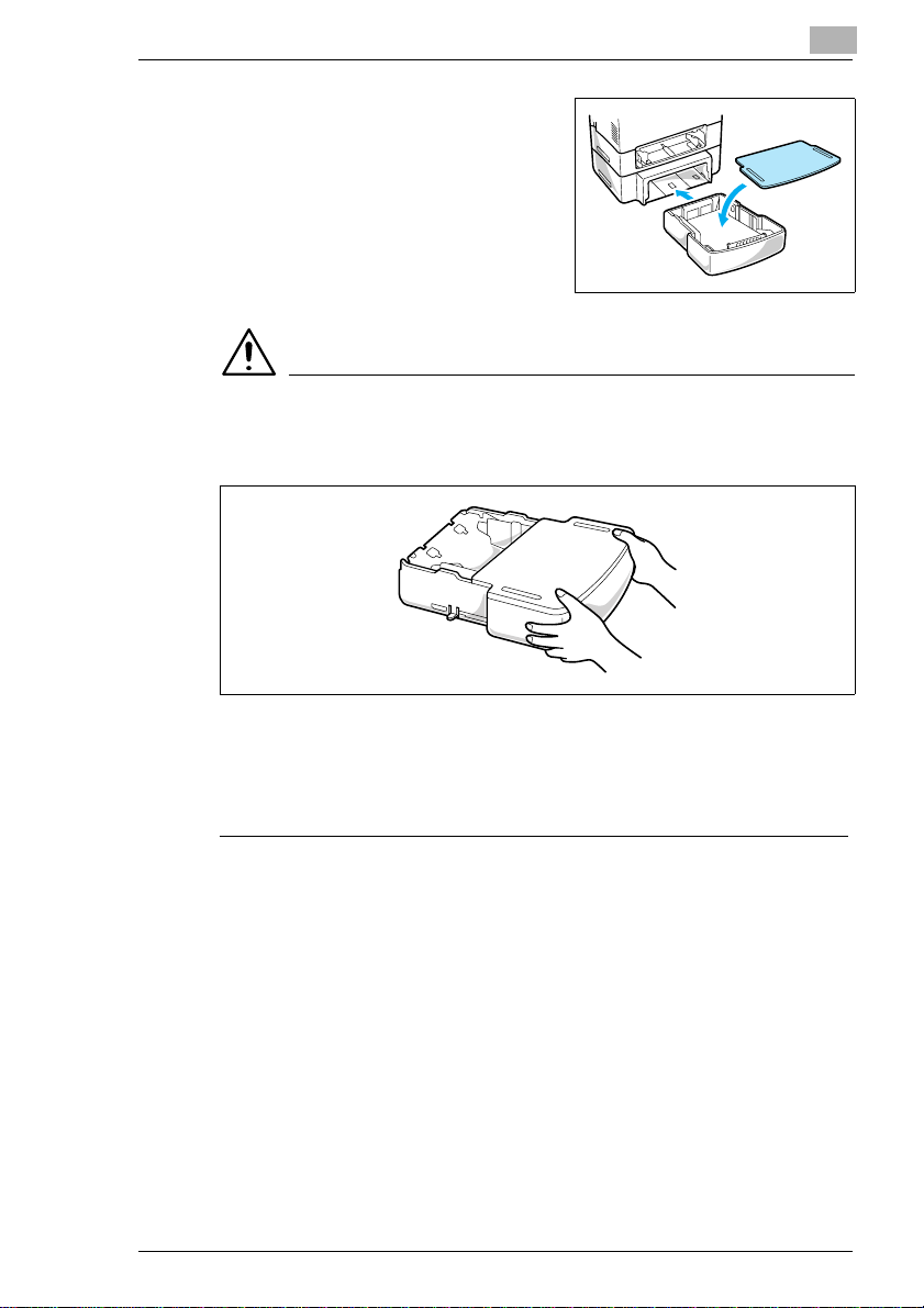
1 Remove the second paper cassette unit and Tray 2 from their
packaging, including the protective tape used to hold the various
components in place.
2 Place the printer on top of the base unit. Make sure to align the
coupling pins of the base unit with the holes located underneath the
printer.
.
3 Load paper onto Tray 2 (see page 4-7).
PagePro 18N 3-9
Page 50

3
Setting-Up
4 Insert Tray 2 into the second paper cassette unit.
.
NOTE
è Be sure to use both hands whenever Tray 2 is being removed from or
inserted into the second paper cassette unit.
3-10 PagePro 18N
Page 51

Setting-Up
3
Connecting the Power Cord
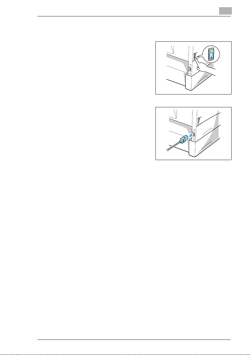
1 Make sure that the printer’s power switch is in the O (Off) position.
2 Connect one end of the power cord that comes with the printer to the
power cord socket. Plug the other end into a power outlet.
PagePro 18N 3-11
Page 52

3
Setting-Up
Loading Paper
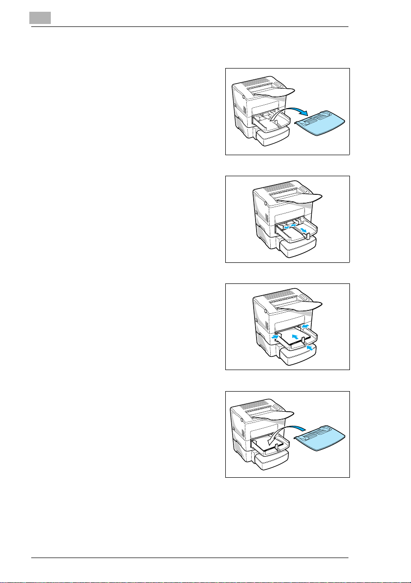
1 Remove the tray cover from Tray 1.
2 Open all three paper size guides.
3-12 PagePro 18N
Page 53

Setting-Up
3
3 Place the paperstack ontothetray,print-side up. Secure the stack by
adjusting the paper size guides.
NOTE
è A maximum level mark on the paper size guide shows how high you
can stack paper on Tray 1. Make sure that paperis stackedno higher
than this mark.
è For detailsonmaking settingsforTray1, see page 5-47andsee page
6-4.
4 Replace the tray cover onto Tray 1.
PagePro 18N 3-13
Page 54

3
Setting-Up
Turning On the Printer
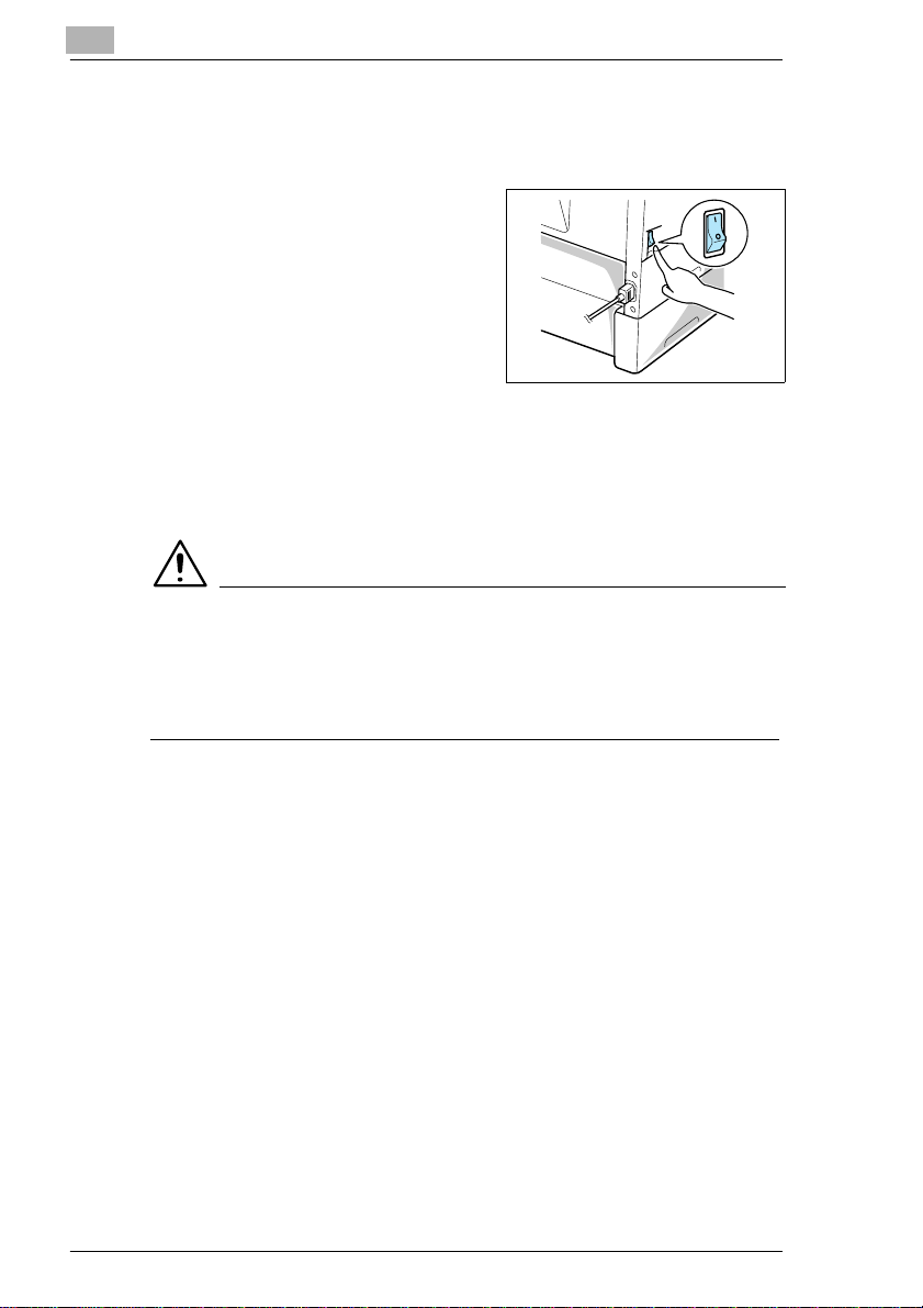
After connecting the printer to a power outlet, press the power switch to
turn it on.
Turningon theprinter causesall theindicatorsonthecontrolpanel tolight,
which indicates that the printer is warming up. In about 23 seconds only
theREADYindicator remainslit,indicatingthatthe printer isreadyto print.
NOTE
è The printerautomaticallyenters a power saving mode if it receivesno
print commands for about 15 minutes. Whenever the printer receives
a print command while in the power saving mode, it starts to warm up
again and takes about 23 seconds before it is ready to print.
3-14 PagePro 18N
Page 55

Setting-Up
3
Testing the Printer
Before connectingto a computer, performthefollowingprocedure to print
a Configuration Page and see if the printer is working correctly.
1 Place the paper onto Tray 1.
2 Make sure that both the Paper and Error indicators are off, and the
Readyindicator ison.This indicatesthereisno existingerror condition
and no data remaining to be printed.
3 Brieflypressthe [panel] buttontostart printingtheConfiguration Page.
PagePro 18N 3-15
Page 56

3
Setting-Up
l Sample Configuration Page
NOTE
è See Chapter “Troubleshooting”of thismanualforinformationon what
to do if the Configuration Page does not print when you press the
[panel] button.
è The Configuration Page can be printed on A4 size paper only.
3-16 PagePro 18N
Page 57

Setting-Up
3
Connectingto a Computer
1 Make sure that the printer and the computer you are connecting it to
are both turned off.
2 Connect one end of the interface cable to the parallel port of the
computer.
3 Connect the other end of the cable to the parallel connector on the
backoftheprinter. Secure thecableusing the two clipsontheparallel
connector.
Cable specifications and pin assignments, see page 9-4.
Network Interface Card (NIC)
This printer is equipped with a 10/100BaseT network interface card. For
details, please see the Network Interface Card User’s Manual.
PagePro 18N 3-17
Page 58

3
3.4 Options
Thissectiondescribes the optionalitemsthatare available forthisprinter:
MemorySIMM(s), DuplexUnit,Third PaperCassetteUnit, andtheAdobe
PostScript ROM-SIMM.
SIMM (Single In-lineMemory Module)
Many errors caused by data overload can be avoided by installing
additional memory into the printer.
This printer comes with 4 MB of memory. You can increase memory
capacity to up to 64 MB by installing an optional 1, 2 , 4, 8, 16 or
32MBSIMMintoone orbothofthetwo memoryconnectorslocatedinside
of the printer.
NOTE
è Memory capacity can be increased to 64 MB by installing two 32 MB
SIMMs into the printer. (However, it will first be necessary to remove
the 4 MB SIMM that comes installed in the printer.) The successful
installation of the expansion memory can be confirmed by printing a
Configuration Page.
Setting-Up
3-18 PagePro 18N
Page 59

Setting-Up
3
Installing the Optional SIMM
WARNING
è Electric shock hazard! Do not remove any cover of the printer that is
not directly specified for removal in the User’s Manual.
1 Turn off the printer and unplug the power cord.
2 Disconnect the parallel cable from the printer.
3 Press the [top cover release] button and open the top cover.
4 Using a screwdriver, loosen and remove the two screws that secure
the exterior side cover to the printer.
5 Clips secure the exterior side cover from the inside of the printer.
Gently maneuver the exterior side cover until the clips release (see
illustration).
.
PagePro 18N 3-19
Page 60

3
Setting-Up
CAUTION
è Do not touch any part of the main circuit inside of the printer.
6 With the exterior side cover removed, the internal side cover of the
printer is exposed. With the screwdriver, loosen and remove the four
screws that secure the internal side cover.
7 Remove the internal side cover to expose the main circuit.
SIMM sockets
3-20 PagePro 18N
Page 61

Setting-Up
3
8 Being careful not to touch the connectionpointsalongtheedge of the
SIMM, insert the SIMM into one of the available sockets on the main
circuit.
Insert the SIMM at an angle as shown and gently swing it into the
socket.
Apply pressure until the SIMM locks into place.
.
9 Replace the internal side cover using the four screws.
PagePro 18N 3-21
Page 62

3
Setting-Up
10 Replace the external side cover using the two screws.
11 Print a Configuration Page (see page 3-16) and check to make sure
that the “Total Memory” item correctly shows the increase in memory
capacity. If it does not, repeat the above steps m aking sure that the
SIMM is installed correctly.
NOTE
è To release the SIMM from the socket, push out on the taps on each
side of the socket.
è After installation of the SIMM, reset the Printer Memory Setting to
reflect the new memory capacity (see page 5-51).
3-22 PagePro 18N
Page 63

Setting-Up
3
Duplex Unit
Your printer supports double-sided printing if the optional duplex unit is
installed. Double-sided documents can be generated for binding along
either the short or long edges of the paper through the printer software.
For more information, see page 4-14.
l Take the duplex unit out of the shipping box.
l Remove the plastic bag and all shipping materials.
l Turn the printer off and then disconnect the power cord and interface
cable from the printer.
PagePro 18N 3-23
Page 64

3
Setting-Up
Installing the Duplex Unit
1 With a screwdriver or similar instrument, remove the flat clip that is
attached to the back of the main unit of the printer.
2 Align the “L” shaped duplex unit to the back of the main unit of the
printer so that the bottom of the “L” is inside of the opening at the
bottom of the printer.
NOTE
è Make sure that the connector of the unit is inserted into the printer
securely.
3-24 PagePro 18N
Page 65

Setting-Up
3
3 With one hand holding the duplex unit in position, use a Phillips
screwdrivertotighten the screwsthatarepermanently attachedtothe
back of the duplex unit.
NOTE
è Hold up the duplex unit with your hand during installation until it is
secured to the printer with the screws.
4 Connect the power cord to the printer and then turn the printer on.
“Connecting the Power Cord”, see page 3-11.
“Turning On the Printer”, see page 3-14.
5 Generate a configurationpageto verify that duplex unit is listed under
the Printer Configuration item.
“Testing the Printer”, see page 3-15.
Printer Configuration
l Tray 2 = Installed
l Tray 3 = Not Installed
l Duplex Unit = Installed
l PostScript = Not Installed
l Network Card = Installed
PagePro 18N 3-25
Page 66

3
Setting-Up
Third Paper Cassette Unit
Thepaperfeedingcapacityof yourprinter canbeincreased by500 sheets
when the optional Tray 3 is installed. Tray 3 is interchangeable with
Tray 2.
Installing the Optional Third Paper Cassette Unit
Take the paper cassette unit out of the shipping box.
ü
Remove the plastic bag and all shipping materials.
ü
Turn the printer off and then disconnect the power cord and interface
ü
cable from the printer.
1 Place the paper cassette unit in the location you have chosen (see
page 3-1“Selectinga Location for thePrinter”). Pulloutthe paper tray.
2 Set the printer onto the third paper cassette unit using the coupling
pins as a guide.
NOTE
è The printer weighs approximately 18 kg (39.7 lbs.). Two people are
recommended to lift it when necessary.
3-26 PagePro 18N
Page 67

Setting-Up
3
3 Insert Tray 3 into the third paper cassette unit.
NOTE
è Be sure to use both hands whenever Tray 3 is being removedfromor
inserted into the third paper cassette unit.
4 Connect the power cord to the printer and then turn the printer on.
“Connecting the Power Cord”, see page 3-11.
“Turning On the Printer”, see page 3-14.
5 Generate a configuration page to verify that Tray 3 is listed under the
Printer Configuration item.
“Testing the Printer”, see page 3-15.
PagePro 18N 3-27
Page 68

3
Setting-Up
Printer Configuration
l Tray 2 = Installed
l Tray 3 = Installed
l Duplex Unit = Not Installed
l PostScript = Not Installed
l Network Card = Installed
3-28 PagePro 18N
Page 69

Setting-Up
Adobe PostScript ROM-SIMM
This printer is equipped with a socket for the installation of an Adobe
PostScript ROM-SIMM. This ROM-SIMM enables the printer to support
the PostScript page description language.
WARNING
è The Adobe PostScript ROM-SIMM is easily damaged by static
electricity. Touch a metal object before you touch the ROM-SIMM.
Take the Adobe PostScript ROM-SIMM out of the shipping box.
ü
Turn the printer off and then disconnect the power cord and interface
ü
cable from the printer.
Installing the Optional Adobe PostScript ROM-SIMM
WARNING
è Electric shock hazard! Do not remove any cover of the printer that is
not directly specified for removal in the User’s Manual.
3
1 Turn off the printer and unplug the power cord.
2 Disconnect the parallel cable from the printer.
3 Press the [top cover release] button and open the top cover.
4 Using a screwdriver, loosen and remove the two screws that secure
the exterior side cover to the printer.
PagePro 18N 3-29
Page 70

3
Setting-Up
5 Clips secure the exterior side cover from the inside of the printer.
Gently maneuver the exterior side cover until the clips release (see
illustration).
CAUTION
è Do not touch any part of the main circuit inside of the printer.
6 With the exterior side cover removed, the internal side cover of the
printer is exposed. With the screwdriver, loosen and remove the four
screws that secure the internal side cover.
3-30 PagePro 18N
Page 71

Setting-Up
3
7 Remove the internal side cover to expose the main circuit.
8 Being careful not to touch the connectionpointsalongtheedge of the
SIMM,inserttheSIMMintothesocketofthemaincircuit.
Insert the SIMM at an angle as shown and gently swing it into the
socket.
Apply pressure until the SIMM locks into place.
9 Replace the internal side cover using the four screws
PagePro 18N 3-31
Page 72

3
Setting-Up
10 Replace the external side cover using the two screws.
11 Connect the power cord to the printer and then turn the printer on.
“Connecting the Power Cord”, see page 3-11.
“Turning On the Printer”,see page 3-14.
12 Generate a configuration page to verify that PostScript is listed under
the Printer Configuration item.
“Testing the Printer”, see page 3-15.
NOTE
è To release the SIMM from the socket, push out on the taps on each
side of the socket
3-32 PagePro 18N
Page 73

Setting-Up
3
Printer Configuration
l Tray 2 = Installed
l Tray 3 = Not Installed
l Duplex Unit = Not Installed
l PostScript = Installed
l Network Card = Installed
PagePro 18N 3-33
Page 74

3
Setting-Up
3-34 PagePro 18N
Page 75

Using the Printer
4 Using the Printer
4.1 Paper
CAUTION
è This printer is designed to print on only the following types of paper.
Type
Special Paper
4
Paper Feeding Port
Tray 1
Tray 2
Tray 3
Manual
Feed
Tray
Plain Paper weighing:
60 to 90 g/m216 to 24 lbs
RecycledPaper weighing:
60 to 90 g/m216 to 24 lbs.
Transparency Sheet
None None None None None None
None None None None None None
Labels
Letter-head
Envelopes
J-Post (Post-card) size:
100 x 148 mm
4" x 5-3/4"
Thick Paper weighing:
90 to 163 g/m224 to 43 lbs.
PagePro 18N 4-1
Page 76

4
Using the Printer
Size
l Standard size
Paper
Feeding
Port
A4
210 x 297 mm
8-1/4” x 11-1 /4”
Tray 1
Tray 2
Tray 3
Manual
Feed Tray
* Each ofthe fivecassettes ofTray 2/Tray3support oneof the fivetypes ofpaper
JIS B5
182 x 257 mm
7-1/4" x 10"
Legal
216 x 356 mm
8-1/2" x 14"
Letter
216 x 279 mm
8-1/2" x 11"
Executive
184 x 267 mm
7-1/4" x 10-1/2"
that are compatible with this printer.
Envelopes and custom sizes (Tray 1 and Manual Feed Tray)
Paper Feeding
Port
Tray 1
Manual Feed
Tray
* Printing is possibleonly if Tray1Settingon thePaper tabof the Printer Control Panel dialog
is setto MultipleSize, (seepage 5-47and see page6-4).
Env. Com10
105 x 241mm
4-1/8" x 9-1/2"
Env. DL
110 x 220 mm
4-5/16" x 8-11/16"
Env. C5
162 x 229 mm
6-3/8" x 9"
Env. B5
176 x 250 mm
6-15/16" x 9-7/8"
Env. M onarch
98 x 190 mm
3-7/8" x 7-1/2"
Custom
86 to 216 x
148 to 356 mm
l Specialty paper is not supported for duplex printing.
4-2 PagePro 18N
3-3/8"to 8-1/2" x
Page 77

Using the Printer
NOTE
è Do not use the following types of paper to avoid reducedprintquality,
a misfeed or a print failure.
Paper already used in a thermal transfer printer or ink jet printer.
Paper that is too thin or too thick.
Paper folded, curled or torn.
Paper having binding holes or perforations.
Paper with surfaces that are too smooth or too rough or with
Paper having special coatings on their surfaces such as carbon
Sheets of various sizes.
Paper not cut on right angles.
Paper bound by glue, staples or clips.
Paper affixed with labels w hich are easy to peel.
Post cards that are warped or bent.
è Envelopes should meet the following requirements:
Sharp folds and edges.
General mailing envelopes without seals on the glued portion.
Having flaps the full widthofthe envelope (unacceptableiftheflap
W rinkle-free, no fasteners.
è Generally, envelopes perform well, but some types may wrinkle. We
strongly recommend testing any type of envelope before buying it in
large amounts.
è For more information, refer to “Loading Paper”.
4
varying surfaces.
paper, heat-sensitive paper and pressure-sensitive paper.
is glued).
PagePro 18N 4-3
Page 78

4
4.2 Loading Paper
There are three sources that can be used to feed paper into the printer:
Tray 1, the manual feed tray, and Tray 2.
Tray 1 is the standard source for supplying paper to the printer. Various
types and sizes of paper can be fed from this tray.
Tray 2 is the secondary paper source. An additional paper source called
Tray 3 is available as an option. See the section of this User’s Manual
entitled “Loading Paper onto Tray 2/Tray 3” for details on using these
trays.
Whenever you are using special size paper, be sure to use the printer
driver installed on the computer to specify the printing area. You m ay
experience some variation in print quality when using special size paper.
Always remember that paper storage conditions greatly affect print
quality. Store paper in its original package. Keep paper out of areas
subject to extreme temperatures or humidity.
Using the Printer
4-4 PagePro 18N
Page 79

Using the Printer
Loading Paper onto Tray 1
You can load up to 250 sheets of standardpaperonto Tray 1. For details
on paper sizes and types, see page 4-1.
1 Remove the tray cover from Tray 1.
2 Open the paper size guides.
4
PagePro 18N 4-5
Page 80

4
Using the Printer
3 Place a stack of paper in the center of Tray 1. Adjust the paper size
guides so that both the left and the right sides of the paper stack are
secure.
NOTES
è A maximum level mark on the paper size guide shows how high you
can stack paper on Tray 1. Make sure that paper is stacked no higher
than this mark.
è Do notloadadditional paperuntilthe paper currentlyloaded onto Tray
1 is completely used.
è Fordetailson making settingsforTray 1, seepage5-47 and seepage
6-4.
4 Replace the tray cover onto Tray 1.
4-6 PagePro 18N
Page 81

Using the Printer
Loading Paper onto Tray 2/Tray 3
NOTE
è Make sure that the Tray 2/Tray 3 cassettefor thepropersizeofpaper
to be used for printing has been installed into the second/thirdpaper
cassette unit. For instructions on inserting ( and removing) the Tray 2/
Tray 3 cassette into (and from) the second/thirdpaper cassette unit,
refer to Chapter 2.
1 Slide Tray 2/Tray 3 out of the second/third paper cassette unit as
illustrated.
4
Tray 2 Tray 3
NOTES
è The cassette is designed to remain in the unit during the normal
loadingandoperation of theprinter.To remove Tray2/Tray3 from the
unit, pull it out as far as it will go without force. Then gently raise the
forward-end up, and remove Tray 2/Tray 3 from the unit.
è Tray 3 is available as an option for this printer. Contact your dealer to
find out how you can acquire this tray to increase the capabilities of
your printer.
PagePro 18N 4-7
Page 82

4
Using the Printer
2 Remove the cassette cover from Tray 2/Tray 3.
3 Press down on the paper lifting plate located inside of Tray 2/Tray 3
until it locks.
4 Place a stack of up to 500 sheets of paper into T ray 2/Tray 3 so that
the side that was facing up when the paper was unwrapped is still
facing up.
4-8 PagePro 18N
Page 83

Using the Printer
NOTE
è A maximum level mark inside the inlet of Tray 2/Tray 3 shows how
high you can stack paper. Make sure that paper is stacked no higher
than this mark.
è Tray 2/Tray 3 does not support landscape-oriented paper-feeding.
è Do notload additionalpaper untilallthe papercurrently onTray2/Tray
3 is completely used up.
5 Replace the cassette cover and insert Tray 2/Tray 3 into the
second/third paper cassette unit.
4
Tray 2
Tray 3
PagePro 18N 4-9
Page 84

4
Using the Printer
Manual Paper Feed
1 Make sure that the tray cover is properly attached to Tray 1.
2 Open the paper size guides.
3 Insert the sheet of paper into the manual feed tray with the side to be
printed facing up.
4-10 PagePro 18N
Page 85

Using the Printer
4 Adjust the paper size guides so that both sides of the paper are
secure.
NOTE
è Insert onlyonesheet ofpaperor one envelope at atimewhen feeding
manually.
4
PagePro 18N 4-11
Page 86

4
Using the Printer
Printing on Envelopes
Themanualfeedtraysupports feedsof Commercial10,Monarch,DL,C5,
and B5 envelopes.
Manually feed envelopes one by one into the manual feed tray.
1 Place the envelope with the side to be printed facing up on the tray.
The flap of the envelope should be facing down and to the left.
2 Makesurethat the envelopeisplaced in the centerof the tray andthat
it is secured by the paper size guides.
NOTE
è Because there is great variation in the quality of paper used for
envelopes, we suggest that you produce test prints of various types
before purchasing any envelope in large quantities for use with this
printer.
Note the following points whenever printing on envelopes.
l Make sure that all edges are creased sharply and that all flaps are
folded correctly.
l Do not use envelopesthatareself-adhesive. Use onlyenvelopesthat
have standard sealing that sticks after it is moistened.
l Use envelopes of which flaps run the entire length of the envelope.
Envelopes that seal at one end will not feed properly.
4-12 PagePro 18N
Page 87

Using the Printer
l Do not use envelopes that have a window. Such envelopes can
seriously damage the printer.
l Do not use envelopes that are wrinkled.
l Never use envelopes that have clasps or any other type of fastener
that can damage the printer.
l Do not store envelopes in an area that is subject to high humidity.
4
PagePro 18N 4-13
Page 88

4
Using the Printer
Duplex Printing
This feature prints document data on both sides of a sheet of paper.
Installation of the optional duplex unit is required to perform duplex
printing.
You can choose either Bind Long Edge or Bind Short Edge when
generating duplex documents.
1. Bind Long Edge
A
A
A
A
1. Bind Short Edge
A
AA
A
The supported paper types and sizes for duplex printing are as follows.
l Paper Type
Plain paper: 64 to 90 g/m2(17to24lb)
Recycled paper: 64 to 90 g/m2(17to24lb)
NOTE
è Do not use special paper (transparencies, labels, envelopes,
letterhead, J-Post and thick paper) for duplex printing.
4-14 PagePro 18N
Page 89

Using the Printer
l Paper Size
A4, A5, JIS B5, Letter, Legal, Executive.
NOTE
è The Long Edge Binding setting of the printer driver cannot be used to
print duplex documents on custom size paper.
Remember the following points when generating duplex documents:
The size of both original documents that will be used to make one
The original document that is loaded first into the duplex unit will
4
duplex document must be the same.
be output face down.
PagePro 18N 4-15
Page 90

4
Using the Printer
4-16 PagePro 18N
Page 91

Printer Driver
5PrinterDriver
This printer driver was especially designed to provide true Windowsbased and DOS printing for your Minolta printer. The driver consists of
threeprograms:the printer statusdisplay,thecontrol panel andthedriver
itself.
IMPORTANT
è This printer driver is located on the CD-ROM that comes with your
printer. If your computer does not have a CD-ROM drive or you wish
to download the updated printer driver, please contact a Minolta
dealer.
5.1 System Requirements
Thefollowingdescribestheminimum systemrequirements forrunning the
Minolta PageWorks/Pro 18/18N printer driver.
Operating System: Microsoft Windows 95, Windows 98, Windows 3.1x,
Windows NT 4.0 or MS-DOS
Personal Computer: IBM-compatible PC with at least a 486DX 16MHz
CPU (Pentium processor recommended)
CD-ROM drive
I/O Interface: IEEE 1284 type-B parallel cable
Memory: At least 8MB of PC RAM
Free Disk Space: Approximately 5MB for files
5
NOTE
è Use of a poor quality parallelcable may adversely affect input.
PagePro 18N 5-1
Page 92

5
Printer Driver
5.2 Installing the Printer Driver Under W indows 95/98
This section provides information on installing the printer driver under
Windows 95/98. It also tells you how to uninstall the printer driver when
necessary.
To Install the Printer Driver from the CD-ROM
1 Turn on your computer and start up Windows 95 or Windows 98.
2 InsertthePrinter DriverCD-ROMintoyour computer’sCD-ROMdrive.
In this example, we will assume that D: is the name of the CD-ROM
drive.
3 Open the Windows Explorer, browse to the CD-ROM drive and
navigate to: D:\DRIVER\WIN95NT\GB
4 Double-click Setup.exe.
NOTE
è The printer driver must be installed using the CD-ROM’s Setup.exe.
Do not use the Add Printerwizardfromthe Printers folder. Installation
throughtheAddPrinter wizardwillpreventthe printerfromperforming
properly.
5 Follow the instructions that appear on your computer screen to
complete the installation.
5-2 PagePro 18N
Page 93

Printer Driver
6 When the following dialog appears, you can assign a name to the
7 When the following dialog appears, check the option(s) that are
5
printer. When the name is as you want it, click [OK].
installed onto your printer. If you want to install the status display,
check the “Install S tatus Display” box. Then click [OK] to display the
next step
8 After the installation is completed, the following dialog appears.
Printing a test page is recommendedto confirm that the printer driver
is correctly installed on your computer.
PagePro 18N 5-3
Page 94

5
Printer Driver
9 A message suggesting that you restart the computer will appear.
Close any applications that are currently active on your desktop and
click [OK] to restart the computer
10 The following dialog appears on the desktop of the computer
11 Make sure thatthe MinoltaPageWorks/Pro18printericonis displayed
in the Printersdialog. Click [Start], point to Settings, and then click
[Printers] to display the Printers dialog
This completes the installation of the printer driver.
5-4 PagePro 18N
Page 95

Printer Driver
To Uninstall the Printer Driver
1 Click the [Start]button,point to Programs, MinoltaPrinterUtilities,and
2 Select [Minolta PageWorks/Pro 18].
5
then click [Uninstall]
3 Click [Uninstall] to proceed with the uninstall operation or [Cancel] to
abort.
PagePro 18N 5-5
Page 96

5
Printer Driver
4 In the next dialog that appears, click [Yes] to restart the computer.
5-6 PagePro 18N
Page 97

Printer Driver
5.3 Installing the Printer Driver Under Windows NT 4.0
This section provides information on installing the printer driver on a
computer running Windows NT 4.0. It also tells you how to uninstall the
printer driver when necessary.
To Install the Printer Driver from the CD-ROM
1 Turn on your computer and start up Windows NT 4.0.
2 Insert the Printer DriverCD-ROMintoyourcomputer’s CD-ROM drive.
In this example, we will assume that D: is the name of the CD-ROM
drive.
3 Open the Windows Explorer, browse to the CD-ROM drive and
navigate to: D:\DRIVER\WIN95NT\GB
4 Double-click Setup.exe.
NOTE
è The printer driver must be installed using the CD-ROM’s Setup.exe.
Do not use the Add Printer wizard from the Printers folder.
5
5 Follow the instructions that appear on your computer screen to
complete the installation.
PagePro 18N 5-7
Page 98

5
Printer Driver
6 SelectLocal Printer.
7 Click the [OK] button to display the next dialog.
8 Select the installation options.
9 Ifthecomputeronto which youareinstalling the driver isaprint server,
check the Server Install checkbox.
NOTE
è If your printer is connected to a Network, we recommend consulting
yournetworkadministratorand referringtothe NetworkInterfaceCard
Manual.
5-8 PagePro 18N
Page 99

Printer Driver
10If you plan to use the printer as a networkprinter, type in a name for
NOTE
è Skip step 10 if you did not check the Server Install option in step 9
5
Share Name.
Example: PP_18
above.
11Click [OK] to display the next dialog.
12When the following dialog appears, you can assign a name to the
printer. When the name is as you want it, click [OK].
PagePro 18N 5-9
Page 100

5
Printer Driver
13 When the following dialog appears, check the option(s) that are
installed onto your printer. If you want to install the status display,
check the “Install Status Display” box. Then click [OK] to display the
next step.
14 After the installation is completed, the following dialog appears.
Printing a test page is recommended to confirm that the printer driver
is correctly installed on your computer.
5-10 PagePro 18N
 Loading...