

Page 1

PK-7 Punch Kit
User Manual
The optional PK-7 Punch Kit is now available to be mounted on the Di850.
This booklet provides the information on the specifications and operation
procedure of the PK-7, as well as the additional information on the “Memory Switch Setting” in the Section 13: Key Operator Mode of Di850 User
Manual. Use this booklet instead when referring to these pages.
Contents
PK-7 Punch Kit User Manual
Overview of the PK-7 Punch Kit..............................................................3
Installation Space........................................................................................................3
Main Body and PK-7 Punch Kit...................................................................................3
Standard/Optional Equipment.....................................................................................4
PK-7 Punch Kit............................................................................................................5
Paper in PK-7 Punch Kit .............................................................................................6
Specifications of PK-7 Punch Kit ................................................................................6
Operation of the PK-7 Punch Kit.............................................................7
Punching File Holes in Copies (Punch) ...................................................................... 7
Empty Trash Basket of PK-7 Punch Kit.................................................10
Memory Switch Setting Additional Information..........................................12
2003. 6
4027-7733-01
Page 2

For U.S.A. Users
FCC Part 15-Radio Frequency Devices
NOTE: This equipment has been tested and found to comply with the limits for a
Class A digital device, pursuant to Part 15 of the FCC Rules. These limits are
designed to provide reasonable protection against harmful interference when the
equipment is operated in a commercial environment. This equipment generates,
uses, and radiate radio frequency energy and, if not installed and used in
accordance with the instruction manual, may cause harmful interference to radio
communications.
Operation of this equipment in a residential area is likely to cause harmful
interference in which case the user will be required to correct the interference at
his own expense.
WARNING: The design and production of this unit conform to FCC regulations, and
any changes or modifications must be registered with the FCC and are subject to
FCC control. Any changes made by purchaser or user without first contacting the
manufacturer will be subject to penalty under FCC regulations.
For Canada Users
Interference-Causing Equipment Standard (ICES-003 Issue 3)
This Class A digital apparatus complies with Canadian ICES-003.
Cet appareil numérique de la classe A est conforme à la norme NMB-003 du
Canada.
Page 3
Overview of the PK-7 Punch Kit
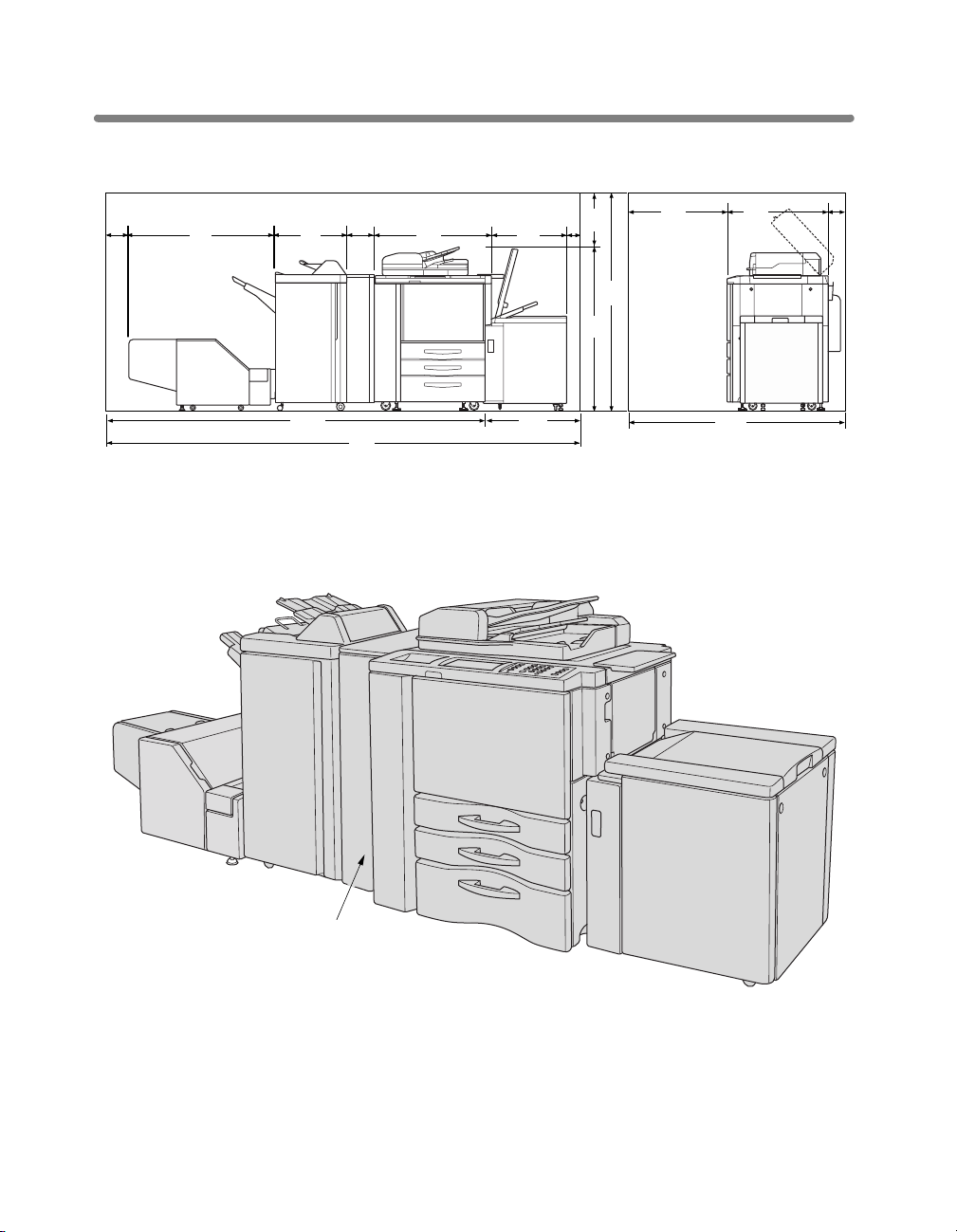
Installation Space
3.9
5.9
(150)
44.05
(1118)
21.5
(546)
6.9
(174)
34.9
(887)
24.65
(626)
(100)
15.7
(400)
(1560)
45.7
(1160)
61.4
37.4
(950)
Unit: inches (mm)
30.5
(775)
4.7
(120)
111.35
(2828)
141.8
(3601)
Di850 + FN-7 + PK-7 + TMG-2 + C-404
Main Body and PK-7 Punch Kit
PK-7 Punch kit
(option)
30.45
(773)
72.6
(1845)
PK-7 Punch kit (option) punches file holes in the output copies.
3
Page 4
Overview of the PK-7 Punch Kit (continued)
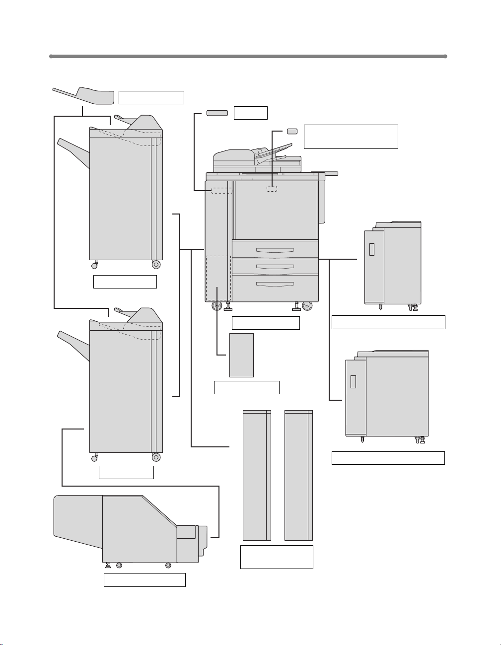
Standard/Optional Equipment
Cover inserter C
FN-115 Finisher
I/F kit N
64MB Memory (M64-1) /
128MB Memory (M128-1)
FN-7 Finisher
TMG-2 Trimming unit
Di850 main body
Printer controller
PK-7 Punch kit or
ZK-3 Z-Fold kit
4
C-403 Large capacity cassette
C-404 Large capacity cassette
Page 5

PK-7 Punch Kit
Overview of the PK-7 Punch Kit (continued)
3 Upper lever
1 Punch kit
front door
4 Knob
5 Left lever
6 Trash basket
2 Right lever
1 Punch kit front door opens to allow removal of mishandled paper or waste paper.
2 Right lever opens to allow removal of mishandled paper.
3 Upper lever opens to allow removal of mishandled paper.
4Knob can be turned to ease removal of mishandled paper.
5 Left lever opens to allow removal of mishandled paper.
6 Trash basket holds waste paper punched out.
5
Page 6

Overview of the PK-7 Punch Kit (continued)
Paper in PK-7 Punch Kit
Paper weight 13 ~ 45* lb
Punching capacity Unlimited
Paper size 2 holes: 11”x17”, 8.5”x14”, 8.5”x11”, 8.5”x11”R, 5.5”x8.5”,
*: Some 45 lb paper types may not be punched easily.
5.5”x8.5”R
3 holes: 11”x17”, 8.5”x11”
Specifications of PK-7 Punch Kit
Punching mode
Number of holes:2 holes or 3 holes
Hole diameter: 0.315” +/- 0.020” (8 mm +/- 0.5 mm)
Hole pitch: 2 holes; 2.756” +/- 0.020” (70 mm +/- 0.5 mm)
3 holes; 4.252” +/- 0.020” (108 mm +/- 0.5 mm)
Dimensions
Width: 6.7 in. (169 mm)
Depth: 26.0 in. (660 mm)
Height: 36.6 in. (930 mm)
Weight
66.1 lb (30 kg)
Power source
Supply from outlet
6
Page 7

Operation of the PK-7 Punch Kit
Punching File Holes in Copies (Punch)
The Punch mode is available only when the PK-7 Punch kit option is installed on the
FN-115/FN-7 Finisher.
When the Punch mode is selected in combination with any of the Primary (Main) tray
output modes, each copied sheet is punched and output to the Primary tray according
to the selected output mode.
DETAILS
• Some staple positions previously selected may conflict with this function.
• Special size paper (STD size (special), Non STD size, Wide size) cannot
be punched.
• The LCC specified as Thick 3 cannot be used.
• If the ATS (Automatic Tray Switching) is in operation while the machine
uses the Punch mode, the punch holes may be slightly off the appropriate
positions.
Reminder!
• Do not punch special paper types such as transparent films, labels, tabbed
sheets, etc. Otherwise, machine trouble may occur in the Punch kit.
• Be sure that the side guide plates of the paper tray are securely aligned
to the paper; otherwise the copies may not be punched in position.
>>>Specifications for Punch Mode<<<
❒ Number of holes: 2 holes or 3 holes
❒ Hole diameter: 0.315" +/- 0.020" (8 mm +/- 0.5 mm)
❒ Hole pitch: 2 holes; 2.756” +/- 0.020” (70 mm +/- 0.5 mm)
❒ Paper size: 2 holes; 11”x17”, 8.5”x14”, 8.5”x11”, 8.5”x11”R, 5.5”x8.5”, 5.5”x8.5”R
❒ Paper weight: 20 ~ 24 lb (20 lb paper recommended)
Thin paper: 16 ~ 19 lb
Thick paper: 25 ~ 45* lb
❒ Incompatible Conditions: Using platen glass (available when using Platen store
mode), Folding, Stapling & Folding, Trimming, Output to Secondary (sub) tray,
8.5"x11"R and 5.5"x8.5" mixed in Mixed Original (3-holes punching only), Non STD
Size, Booklet, Transparency Interleave
3 holes; 4.252” +/- 0.020” (108 mm +/- 0.5 mm)
3 holes; 11"x17", 8.5"x11"
* Some 45 lb paper types may not be punched easily.
2.756"
(70 mm)
2 holes
4.252"
(108 mm)
3 holes
7
Page 8

Operation of the PK-7 Punch Kit (continued)
1. Touch OUTPUT APPLI. on the Basic Screen
The Output Mode popup menu will be displayed.
2. Touch MAIN TRAY, if not highlighted.
3. Touch PUNCH.
The Punch Position popup menu will be displayed.
4. Specify the number of punch holes and punch positions.
Touch the desired punch hole/position key on the screen to highlight
it.
5. Touch OK on the Punch Position popup menu to restore the Output
Mode popup menu.
6. Touch OK on the Output Mode popup menu to complete the setting
and return to the Basic Screen.
The selection made in punch position will be displayed in the OUTPUT icon area.
8
Page 9

Operation of the PK-7 Punch Kit (continued)
7. Specify the original set direction.
Touch SPECIAL ORIGINAL on the Basic Screen to display the Special Original
popup menu.
Touch to select the desired original set direction, then touch OK to return to the Basic
Screen.
8. Select additional copying features, as required.
9. Enter the desired print quantity from the control panel keypad.
HINT
See the main body User Manual, p. 3-7 for details on setting print quantity.
10. Position originals in the document handler.
HINT
See the main body User Manual, p. 3-2 to p. 3-5 for details on positioning
originals.
11. Press [Start].
CAUTION
When the finisher exit tray capacity is exceeded due to the
print quantity selected, remove the copied sets as they exit;
otherwise, mishandled paper will occur.
9
Page 10

Empty Trash Basket of PK-7 Punch Kit
When the trash basket becomes full, “Trash basket of Punching unit is full / Please
empty trash basket” message will be displayed on the touch screen, and the finished
set will be output without being punched even if Punch mode is selected.
Follow the procedure below to empty the trash basket.
1. Open the Punch kit front door with Finisher door handle.
2. Withdraw the trash basket.
10
Page 11

Empty Trash Basket of PK-7 Punch Kit (continued)
3. Empty the trash basket.
4. Return the trash basket to its original position, then close the Punch
kit front door securely.
11
Page 12

Memory Switch Setting Additional Information
The following menu items are added to the Memory Switch Setting of the Key Operator Mode.
SW No. Item Setting (default is underlined)
No. 46: No. of punch (driver no req.)
No. 47: I/P SCAN Address manual input Permission
/ Prohibition
12
 Loading...