

Page 1

Table of Contents
1 Page Scope Light
Welcome .........................................................................................2-1
Trademark Acknowledgements ......................................................2-1
1.1 System Requirements ................................................................. 2-2
Computer........................................................................................2-2
Digital Copier ..................................................................................2-2
Pi5501 Printer Controller.................................................................2-2
1.2 Access........................................................................................... 2-3
1.3 Operation...................................................................................... 2-4
1.4 Logging In to the Admin Mode ................................................... 2-4
1.5 Screen Configuration................................................................... 2-5
1.6 System Tab................................................................................... 2-7
Summary.........................................................................................2-7
Details .............................................................................................2-8
Input Tray........................................................................................2-8
Output Tray.....................................................................................2-9
Hard Disk Status...........................................................................2-10
ROM Version.................................................................................2-11
Interface Information.....................................................................2-12
Consumable Status ......................................................................2-13
Preference.....................................................................................2-14
Save Setting..................................................................................2-16
Online Assistance .........................................................................2-18
1.7 Job Tab ....................................................................................... 2-19
Print Job Management .................................................................2-19
File Download ...............................................................................2-21
1.8 Printer Tab.................................................................................. 2-22
Settings.........................................................................................2-22
Paper Handling .............................................................................2-22
Page Layout..................................................................................2-24
Printer Setting ...............................................................................2-25
Printer Front Panel........................................................................2-27
Test Print.......................................................................................2-28
Font Information............................................................................2-29
Printer Reset .................................................................................2-30
Maintenance .................................................................................2-31
Pi5501
Page 2

Local Interface..............................................................................2-32
1.9 Scanner Tab ................................................................................2-33
Destinations.................................................................................. 2-33
E-mail Destinations ......................................................................2-33
Configuring an E-Mail Destination................................................2-34
File Destinations...........................................................................2-36
Configuring a File Destination ......................................................2-37
SMTP & FTP Configuration .......................................................... 2-39
External Open Link.......................................................................2-41
1.10 Network Tab................................................................................2-42
Summary ......................................................................................2-43
TCP/IP Configuration ...................................................................2-44
NetWare Configuration.................................................................2-46
NetWare Setting ........................................................................... 2-47
NetWare Status ............................................................................2-49
AppleTalk Configuration............................................................... 2-50
IPP Configuration .........................................................................2-51
WINS Configuration......................................................................2-53
Reset ............................................................................................ 2-55
Maintenance.................................................................................2-56
Status List.....................................................................................2-57
Pi5501
Page 3

Page Scope Light
1 Page Scope Light
Welcome
PageScope Light for Pi5501 is a device control utility program provided
by the HTTP server built into the Pi5501 (printer controller for Digital
Copier). With a standard Web browser, this utility can be used as an
interface for remote control of the Digital Copier.
Trademark Acknowledgements
Minolta is a registered trademark of MINOLTA CO., LTD. PageScope is a
trademark of MINOLTA CO., LTD.
Apple and Macintosh are registered trademarks of Apple Computer, Inc.
Ethernet is a registered trademark of Xerox Corporation.
Linux is a registered trademark of Linus Torvalds.
Microsoft, Windows, and Windows NT are registered trademarks of
Microsoft Corporation.
Netscape Communications, the Netscape Communications logo,
Netscape Navigator, Netscape Communicator, and Netscape are
trademarks of Netscape Communications Corporation.
PCL is a registered trademark of Hewlett-Packard Company Limited.
PostScript is a registered trademark of Adobe Systems, Inc.
Solaris is a trademark of Sun Microsystems, Inc.
All other product names are trademarks or registered trademarks of their
respective holders.
Copyright 2001 MINOLTA CO., LTD.
The information contained in this manual is subject to change without
notice.
1
Pi5501 1-1
Page 4
1
1.1 System Requirements
The following items are required to use this utility.
Computer
l Software
Operating System Web Browser
Windows 95/98/NT 4.0/2000 Internet Explorer 4 or higher
Macintosh System 7 or higher Internet Explorer 4.5 or higher
Solaris 2.5.1/2.6/7 (2.7) Netscape Navigator 4 or higher
Linux Netscape Navigator 4 or higher
l NIC (Network Interface Card)
l Ethernet
l TCP/IP Protocol
Digital Copier
Pi5501 Printer Controller
Page Scope Light
Netscape Navigator 4 or higher
Netscape Navigator 4 or higher
1-2 Pi5501
Page 5

Page Scope Light
1.2 Access
PageScope Light for Pi5501 can be accessed directly from a Web
browser.
1 Start the Web browser.
2 In the URL field, enter the IP address of the printer controller as shown
below.
(Example) When the IP address of the printer controller is
192.9.200.200:
3 This causes PageScope Light for Pi5501 screen to appear.
1
http://<IP address of printer controller>/
http://192.9.200.200/
Pi5501 1-3
Page 6
1
1.3 Operation
PageScope Light for Pi5501 operation is identical to that for Internet Web
pages. Clicking a hot link jumps to the link destination, and the [Back] and
[Forward] buttons scroll through pages backwards and forward.
1.4 Logging In to the Admin Mode
After you log in to PageScope Light in the Admin Mode, you can change
the configuration of the Digital Copier settings.
1 Type the administrator password into the “Admin Password” box.
The initial default administrator password is “sysadm”. See
page 1-14 for information about how to change the password.
2 Click the [Log-in] button to log in to the Admin Mode.
3 When you want to log out, click the [Log-out] button.
NOTE
è Log out is performed automatically if no operation is performed for
more than 10 minutes.
è On the “Network” tab, a password input text box appears on each
setting screen. You must be able to input the correct password in
order to change “Network” tab settings. The password you should
input here is the same as the Admin Password you input on other
tabs.
Page Scope Light
1-4 Pi5501
Page 7
Page Scope Light
1.5 Screen Configuration
The configuration of the PageScope Light for Pi5501 screen is shown
below.
NOTE
è Screen images shown in this manual may differ slightly from actual
ones. Also note that specifications are subject to change without prior
notice.
➀
➃
1
➁
➂
➅
1. Minolta PageScope Light Logo
Clicking the logo jumps to the Website below.
www.minolta.com
2. Status Display
The current status of the Digital Copier is indicated by both icons and
text. The message READY appears when the Digital Copier is
operating normally. For full details about screen contents, see page
1-57.
Pi5501 1-5
➄
Page 8

1
Page Scope Light
3. Tabs
Use the tabs to select the category of items you want to display. See
the following sections of this document for detailed information about
each tab.
4. Menus
Use the menus to select information or setting items. The menus that
appear depend on the currently selected tab.
See the following sections of this document for detailed information
about each menu.
5. Information and Settings Display
This display shows information or settings in accordance with the
selected menu item.
6. Admin Password
Inputting the admin password provides access to the Admin Mode.
See page 1-6 for more information.
1-6 Pi5501
Page 9
Page Scope Light
1.6 System Tab
The “System” tab shows information about and settings for the Digital
Copier system configuration.
Summary
This screen is the initial screen when you access http://<IP address of
printer controller> with your Web browser. You can also display it by
clicking the “Summary” menu on the “System” tab. It shows the current
Digital Copier system configuration.
1
l Device Status
This area uses graphics and text to show the configuration of options
installed on the Digital Copier.
l Operational Panel Display
This area shows the printer controller message display. Messages are
the same as the Status Display messages that appear in the upper
part of the window.
l Configuration Summary
This area shows an overview of the current Digital Copier system
configuration.
Pi5501 1-7
Page 10
1
Page Scope Light
Details
Sub-menus appear when you click the “Details” menu on the “System”
tab. Clicking a sub-menu under the “Details” menu displays information
about the applicable unit.
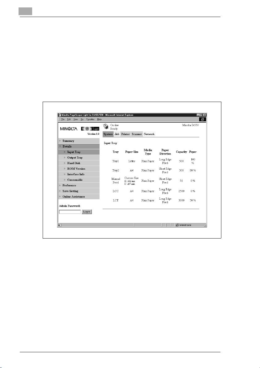
Input Tray
This screen appears when you click the [Input Tray} sub-menu under the
“Details” menu. It shows the configuration of all the Input Trays installed
on the Digital Copier.
l Tray
Tray name
l Paper Size
Size of paper loaded in the tray
l Media Type
Type of media loaded in the tray
l Paper Direction
Orientation of paper loaded in the tray
l Capacity
Maximum number of sheets that can be loaded in the tray
l Paper
Amount of paper remaining in the tray (%)
1-8 Pi5501
Page 11
Page Scope Light
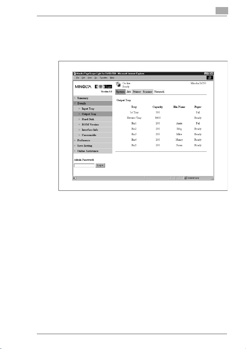
Output Tray
This screen appears when you click the “Output Tray” sub-menu under
the “Details” menu. It shows the configuration of all the Output Trays
installed on the Digital Copier.
1
l Tray
Tray name
l Capacity
Maximum number of sheets the tray can hold
l Bin Name
When the mail bin finisher is installed, owner name assigned to each
bin See page 1-23 for information about how to specify a bin name.)
l Paper
Tray status (Shows “Full” when the tray is unable to receive any more
paper, and “Ready” when it is.)
Pi5501 1-9
Page 12
1
Page Scope Light
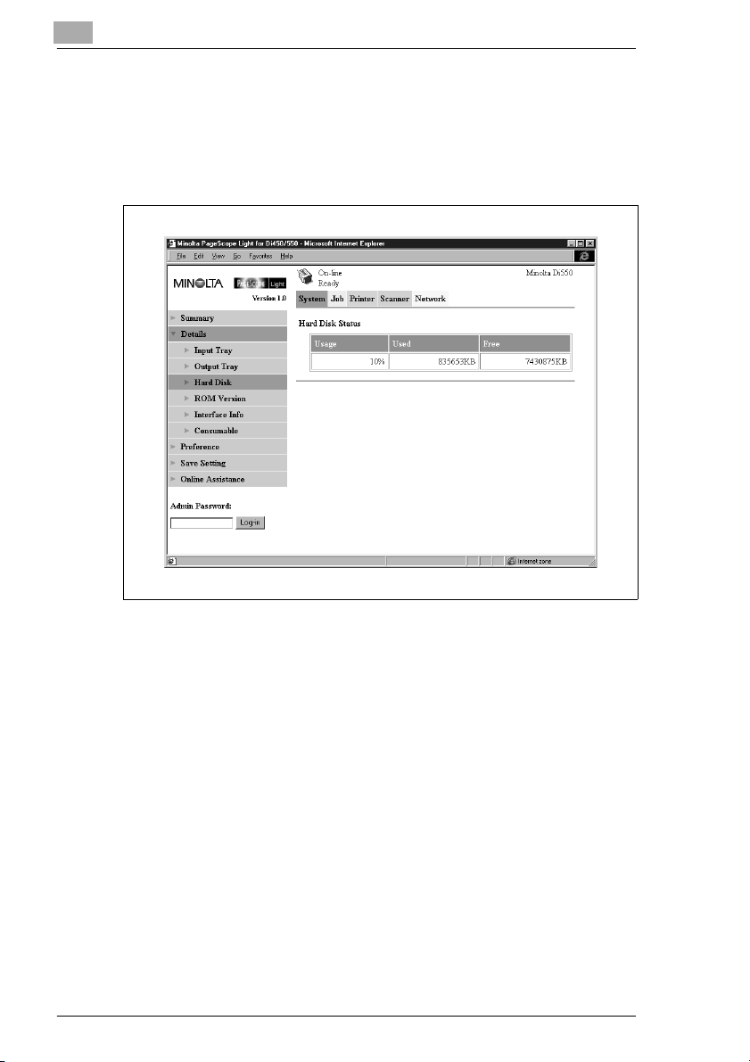
Hard Disk Status
This screen appears when you click the “Hard Disk” sub-menu under the
“Details” menu. It shows the status of the hard disk installed on the
printer controller. This information is not displayed when there is no hard
disk installed on the printer controller.
l Usage
Percent of hard disk space used (%)
l Used
Amount of hard disk space used (KB)
l Free
Amount of hard disk space free (KB)
1-10 Pi5501
Page 13
Page Scope Light
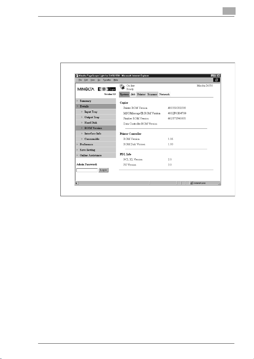
ROM Version
This screen appears when you click the “ROM Version” sub-menu under
the “Details” menu. It shows information about the on-board memory of
the Digital Copier and the printer controller.
1
l Copier
Version of ROM installed on the Digital Copier
l Printer Controller
Version of firmware installed on the printer controller
l PDL Info
Version of printer control codes (PCL or PostScript) used by the
printer controller
Pi5501 1-11
Page 14
1
Page Scope Light
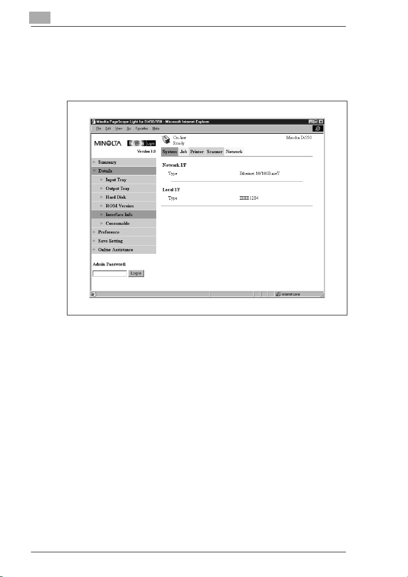
Interface Information
This screen appears when you click the “Interface Info” sub-menu under
the “Details” menu. It shows information about the printer controller
interface.
l Network I/F
Network interface type
l Local I/F
Local port type
1-12 Pi5501
Page 15
Page Scope Light
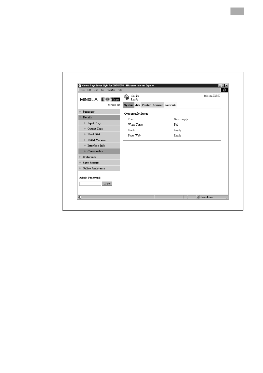
Consumable Status
This screen appears when you click the “Consumable” sub-menu under
the “Details” menu. It shows the current status of Digital Copier
consumables. For information about consumables, see the Digital Copier
Operator’s Manual.
1
l Toner
Remaining toner
l Waste Toner
Remaining waste toner bottle capacity
l Staple
Remaining staples
l Fuser Web
Remaining oil in fuser web unit
Pi5501 1-13
Page 16
1
Page Scope Light
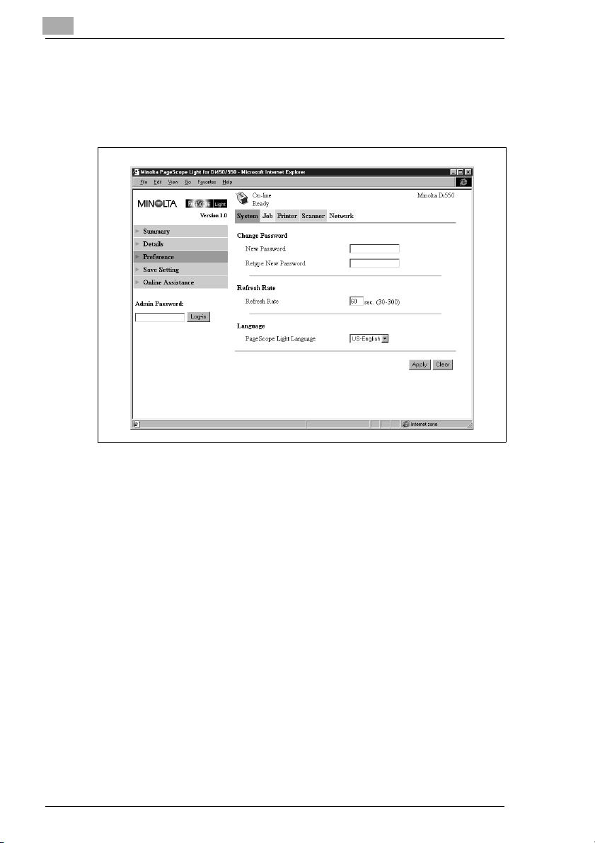
Preference
This screen appears when you click the “Preference” menu on the
“System” tab. It lets you make changes to the PageScope Light
environment.
l Change Password
When changing the password, type the new password into the “New
Password” text box. Type the same password into the “Retype New
Password” text box for confirmation. The password must be at least
four characters and can be up to eight characters long.
l Refresh Rate
Type in a value to specify the number of seconds between screen
refreshes. You can input a value from 30 to 300 seconds. The default
setting is 60 seconds.
l Language
Select the screen language you want to use for PageScope Light.
m US-English
m UK-English
m German
m French
m Italian
m Dutch
m Spanish
m Danish
m Czech
1-14 Pi5501
Page 17

Page Scope Light
l [Apply] Button
Click this button to apply any settings you have input or selected up
to this point.
l [Clear] Button
Click this button to cancel any settings you have input or selected up
to this point.
1
Pi5501 1-15
Page 18
1
Page Scope Light
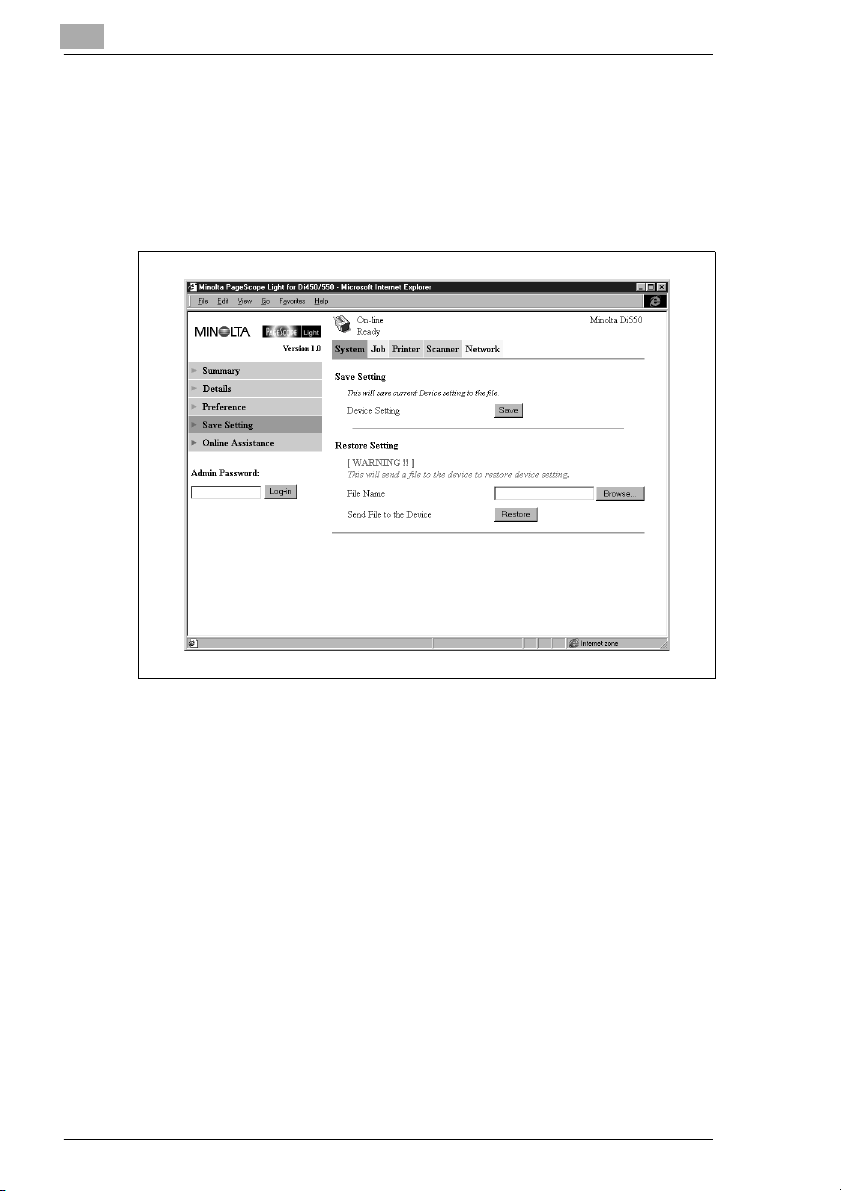
Save Setting
This screen appears when you click the “Save Setting” menu on the
“System” tab. You can use the screen that appears to save the Digital
Copier setup to a file. Note that only settings you can make with
PageScope Light are saved to the file. Saved setups can be recalled to
set up the Digital Copier when required.
l Save Setting Section
m Device Setting
Click the [Save] button to display a dialog box for saving the
Digital Copier setup. Specify the destination folder and file name,
and then click [OK] on the dialog box to save the setup in the
folder. The default setup file name is PI5501_PRF.BIN.
l Restore Setting Section
m File Name
Type in the full path name to the file that contains the setup you
want to restore. You can also click the [Browse] button to display
a dialog box for selecting the file.
m Send File to the Device
Clicking the [Restore] button sends the setup file specified in “File
Name” and changes the settings of the Digital Copier accordingly.
1-16 Pi5501
Page 19

Page Scope Light
IMPORTANT!
è Clicking the [Restore] button changes the setup of the Digital Copier
in accordance with the specified setup file. Make sure you select the
correct file that contains the setup you want before clicking [Restore].
1
Pi5501 1-17
Page 20

1
Page Scope Light
Online Assistance
This screen appears when you click the “Online Assistance” menu on the
“System” tab. It shows information and lets you make settings related to
product support.
l Contact
Type in the name of your product support counter.
l Contact Tel Number
Type in the phone number of your product support counter.
l Product Help URL
Type in the URL of your product information Website. Clicking the
Product Help URL jumps to the Website you specify here.
l Minolta Corporate URL
Type in the URL to the Minolta home page. Clicking the Minolta
Corporate URL jumps to the Website you specify here.
l Tel Number for Supplies and Accessories
Type in the telephone number of the support counter you need to
contact to order consumables and accessories.
l [Apply] Button
Click this button to apply any settings you have input up to this point.
l [Clear] Button
Click this button to cancel any settings you have input up to this point.
1-18 Pi5501
Page 21

Page Scope Light
1.7 Job Tab
You can use the “Job” tab for managing print jobs sent to the Digital
Copier from clients, and for sending files directly from clients for printing.
Print Job Management
This screen appears when you click the “Print Job Management” menu
on the “Job” tab. Use this screen to manage print jobs sent from clients
to the Digital Copier.
1
l Job Status Section
This section lists the jobs sent to the Digital Copier.
m No Job number
m Name Print data file name
m Owner Name of user who sent the job
m Total Pages Total number of pages in the job
m # of Copies Number of copies in the job
m Time Time job was placed in the queue
m Status Job processing status
m [Delete Selected Job] Button
Clicking this button deletes all jobs who have check marks in the
leftmost column.
Pi5501 1-19
Page 22

1
Page Scope Light
l Secure Printing Section
This section lists confidential print jobs. When printing a secure print
job, the same password that was input when the print command was
executed on the client must be input on the printer.
m No Job number
m Name Print data file name
m Owner Name of user who sent the job
m Total Pages Total number of pages in the job
m # of Copies Number of copies in the job
m Time Time job was placed in the queue
m Status Job processing status
m [Delete Selected Job] Button
Clicking this button deletes all jobs that have check marks in the
leftmost column.
l Incomplete Job Queue Section
This section lists jobs for which an alternate process was performed
or which were removed from the queue because normal print
processing was impossible for some reason.
m No Job number
m Name Print data file name
m Owner Name of user who sent the job
m Total Pages Total number of pages in the job
m # of Copies Number of copies in the job
m Time
Time alternate process was performed or job was removed
m Reason
Reason normal print processing was impossible
l Scanner Log Section
This section shows a log of scanner data communication.
m No Job number
m Address Name associated with addresses
m Mode Communication mode (e-mail or FTP)
m Date Communication date
m Time Send start time
m Result Communication result
m [Print Button]
Click to print a single scanner communication log sheet.
1-20 Pi5501
Page 23

Page Scope Light
File Download
This screen appears when you click the “File Download” menu on the
“Job” tab. You can use this screen to send a file directly from a client to
the Digital Copier.
1
l File Name
Type in the full path to the file you want to print. You can also click the
[Browse] button to display a dialog box for selecting the file.
l Send File to Printer
Clicking the [Send] button sends the file specified by “File Name” to
the Digital Copier and prints it.
Pi5501 1-21
Page 24

1
1.8 Printer Tab
The “Printer” tab shows information and settings for printing on the
Digital Copier.
Settings
Sub-menus appear when you click the “Settings” menu on the “Printer”
tab. Click the sub-menus to display screens for changing the printer
setup.
Paper Handling
This screen appears when you click the “Paper Handling” sub-menu
under the “Settings” menu. Use this screen to configure the input tray
and output bins.
Page Scope Light
l Input Section
m Copies
Input a value indicating the number of copies.
m Priority Source
Specify the default input tray. The menu shows only the trays that
are currently available for selection.
1-22 Pi5501
Page 25

Page Scope Light
l Output Section
m Bin
m Bin Name
m [Restore Factory Default] Button
m [Apply] Button
m [Clear] Button
1
Bin names when mail bin manager is installed
Type in the name of the user of each bin. You can input up to 32
characters.
Click this button to return settings to their initial factory defaults.
Click this button to apply any settings you have input up to this
point.
Click this button to cancel any settings you have input up to this
point.
Pi5501 1-23
Page 26

1
Page Scope Light
Page Layout
This screen appears when you click the “Page Layout” sub-menu under
the “Settings” menu. Use this screen to configure the print document
page layout.
l Paper Size
Select the page layout paper size to be used when printing is
performed without a paper size specified by the client.
l Duplex
Use this setting to turn two-side printing on and off, and to specify
either long-edge binding or short-edge binding.
l [Restore Factory Default] Button
Click this button to return settings to their initial factory defaults.
l [Apply] Button
Click this button to apply any settings you have input up to this point.
l [Clear] Button
Click this button to cancel any settings you have input up to this point.
1-24 Pi5501
Page 27

Page Scope Light
Printer Setting
This screen appears when you click the “Printer Setting” sub-menu under
the “Settings” menu. Use this screen to configure the printer controller.
1
l Printer Settings Section
m Printer Language
Select the printer control code type.
m Download Font/PS Header Hold on RAM
When the box next to this option is checked, downloaded fonts
and PostScript header remain in printer controller RAM as long as
power is supplied to the printer controller. This option appears
after printer controller memory has been increased.
l PostScript Settings Section
m Error Print
When the box next to this option is checked, an error message is
printed whenever a PostScript error is generated.
Pi5501 1-25
Page 28

1
Page Scope Light
l PCL Settings Section
m Orientation
Specify the orientation of the printed page.
m Font Size
Type in a value specifying the size in points for proportional fonts.
m Pitch
Type in a value specifying the number of characters per horizontal
inch for uniform space fonts.
m Font No.
Type in a font number.
m Symbol Set
Select the symbol set you want to use with the font. The default
symbol set is used if the symbol set you select is currently not
available.
m Form Length
Type in a value specifying the number of lines per page.
l [Restore Factory Default] Button
Click this button to return settings to their initial factory defaults.
l [Apply] Button
Click this button to apply any settings you have input up to this point.
l [Clear] Button
Click this button to cancel any settings you have input up to this point.
1-26 Pi5501
Page 29

Page Scope Light
Printer Front Panel
This screen appears when you click the “Operational Panel” menu on the
“Printer” tab. It provides on-screen emulation of the printer controller’s
operational panel.
1
l Display
This area shows the printer controller message display. Messages are
the same as the Status Display messages that appear in the upper
part of the window.
l Online Button
Toggles the printer controller network connection on line and off line
l Proceed Button
Click this button to force printing of the job whose data is still in the
controller.
Pi5501 1-27
Page 30

1
Page Scope Light
Test Print
This screen appears when you click the “Test Print” menu on the “Printer”
tab. It lets you select a test print page and execute a test print operation.
l Config Page
Insert a check mark into the box to print the printer controller setup
page.
l PCL Font List
Insert a check mark into the box to print the PCL font list.
l PostScript Font List
Insert a check mark into the box to print the PostScript font list.
l Network Config
Insert a check mark into the box to print the network configuration.
l [Print] Button
Click this button to execute a test print operation.
1-28 Pi5501
Page 31

Page Scope Light
Font Information
This screen appears when you click the “Font Info” menu on the “Printer”
tab. It shows a list of PCL fonts and PostScript fonts built into the printer
controller.
1
l PCL Internal Font
PCL fonts built into the printer controller
l PCL Download Font
PCL fonts downloaded from the computer to the printer controller
l PostScript Font
PostScript fonts built into the printer controller
l PostScript Download Font
PostScript fonts downloaded from the computer to the printer
controller
l Font Name
Font name
l Font ID
Unique control number for each downloaded font
l Font #
Downloaded font number
l Location
Storage location of the font (ROM, RAM, HDD)
Pi5501 1-29
Page 32

1
Page Scope Light
Printer Reset
This screen appears when you click the “Printer Reset” menu on the
“Printer” tab. Use this screen to reset the printer controller.
l Printer Controller
Clicking the [Reset] button displays a confirmation message asking if
you want to perform the reset. Click [Yes] to reset the printer
controller. Applicable users are informed if a reset is executed while a
print operation or data receive operation is in progress.
1-30 Pi5501
Page 33

Page Scope Light
Maintenance
This screen appears when you click the “Maintenance” menu on the
“Printer” tab. Use this screen to format the hard disk drive and to update
the printer controller firmware.
1
l HDD Format Section
m HDD Format
Use this section to format the hard disk drive. Clicking the
[Format] button displays a confirmation screen. Click [Yes] to
format the hard disk.
l Firmware Update Section
m File Name
Type in the full path to the firmware definition file you want to
download to the printer controller. You can also click the [Browse]
button to display a dialog box for selecting the file.
m Send new Firmware to Printer
Click the [Send] button to download the firmware to the printer
controller.
l Restore Factory Default Section
m Printer Controller FW
Use this section to return printer controller settings to their initial
factory defaults. Clicking the [Restore] button displays a
confirmation screen. Click the [Yes] button to restore the initial
factory default settings.
Pi5501 1-31
Page 34

1
Page Scope Light
Local Interface
This screen appears when you click the “Local I/F” menu on the “Printer”
tab. Use this screen to view and configure local interface information.
l Timeout
Input a value specifying how much time, in seconds, should be
allowed to pass after data is received through the parallel port before
it is decided that a job is finished.
l I/O Buffer Size
I/O buffer size
l Bi-Directional
Bi-directional communication setting
l Timing
Printer data read timing
1-32 Pi5501
Page 35

Page Scope Light
1.9 Scanner Tab
The “Scanner” tab contains settings for configuration of the Digital
Copier scanner function. For details about the scanner function, see the
separate Digital Copier Scanner Mode Operator’s Manual.
Destinations
Sub-menus appear when you click the “Destinations” menu on the
“Scanner” tab. Use the sub-menus to specify the destination of the
scanned data.
E-mail Destinations
This screen appears when you click the “E-mail Destinations” sub-menu
under the “Destination” menu. It lists the E-mail Destinations that are
currently registered.
1
l Clicking an unused cell inside the E-mail Destination List displays a
screen for registering a new E-mail Destination. See page 1-34 for
more information.
l Clicking an existing E-mail Destination number or name displays a
screen showing the details of that destination. See page 1-34 for
more information.
l To delete an E-mail Destination, click the [del] button next to the
destination you want to delete.
Pi5501 1-33
Page 36

1
Page Scope Light
Configuring an E-Mail Destination
This section describes the settings you can make on the screens for
registering a new E-mail destination and for changing the configuration
of an E-mail destination.
l E-mail Destination Section
m No.
E-mail Destination number
m Destination Name
Type in the name of the E-mail Destination. You can input up to
72 characters.
m Destination Address
Type in the e-mail address of the destination. You can input up to
72 characters.
l Scanning Mode Section
m Compression
Select the compression method to be used when scanned data is
sent as an e-mail attachment.
m [Apply] Button
Click this button to apply any settings you have input up to this
point.
1-34 Pi5501
Page 37

Page Scope Light
m [Clear] Button
m Icon
1
Click this button to cancel any settings you have input up to this
point.
Click to return to the previous screen.
Pi5501 1-35
Page 38

1
Page Scope Light
File Destinations
This screen appears when you click the “File Destinations” sub-menu
under the “Destination” menu. It lists the File Destinations that are
currently registered.
l Clicking an unused cell inside the File Destination List displays a
screen for registering a new File Destination. See page 1-37 for more
information.
l Clicking an existing File Destination number or name displays a
screen showing the details of that destination. See page 1-37 for
more information.
l To delete an File Destination, click the [del] button next to the
destination you want to delete.
1-36 Pi5501
Page 39

Page Scope Light
Configuring a File Destination
This section describes the settings you can make on the screens for
registering a new file destination and for changing the configuration of a
file destination.
1
l File Destination Section
m File Destination No.
File Destination number
m Destination Name
Type in the name of the File Destination. You can input up to 72
characters.
m FTP Server Address
Type in the IP address of the FTP site.
m Directory
Type in the directory of the FTP site where the scan data is
located. You can input up to 128 characters.
m Use Proxy
Put a check mark into this box to enable access of the FTP site via
a proxy.
m Remote Port Number
When not using a proxy, input the FTP port number. You can input
a value from 1 to 65535.
Pi5501 1-37
Page 40

1
Page Scope Light
l Account Information Section
m Anonymous
Select this option to enable log in to the FTP site using an
anonymous account.
m Private Site
Make the following settings for non-anonymous account log in on
the FTP site.
User Name:
Ty pe in th e user n ame for log ging in to the FTP site. You can input
up to 64 characters.
Password:
Type in the password for logging in to the FTP site. You can input
up to 40 characters.
Confirm:
Re-input the password to confirm it.
l Scanning Mode Section
m Compression
Select the compression method to be used when scanned data is
send by FTP.
m [Apply] Button
Click this button to apply any settings you have input up to this
point.
m [Clear] Button
Click this button to cancel any settings you have input up to this
point.
m Icon
Click to return to the previous screen.
1-38 Pi5501
Page 41

Page Scope Light
SMTP & FTP Configuration
This screen appears when you click “SMTP & FTP Configuration” on the
“Scanner” tab. Use this screen to make SMTP and FTP settings.
1
l SMTP Configuration Section
IMPORTANT!
è You must provide information for the SMTP Server Address and
Reply Address when you are using the Send to E-mail function. E-mail
cannot be sent if these settings are left blank.
m SMTP Server Address
Type in the IP address of the SMTP server.
m Default Subject for E-mail Attachment
Type in the default subject when distributing scanner data as email attachments.
m Default Subject for FTP Notification
Type in the default subject when informing by e-mail the URL of
the FTP site where scan data is left.
m Reply Address
Type in the mail address for a mail replay showing the error
message when a send error is generated.
Pi5501 1-39
Page 42

1
Page Scope Light
m SMTP Connection Timeout
Input the SMTP server connection timeout in seconds. You can
input a value from 1 to 120 seconds.
m Default Compression
Select the default compression method to be used when
distributing scanned data as direct mail.
l FTP Proxy Configuration Section
m FTP Proxy Server Address
Type in the IP address of the FTP proxy server.
m Remote Port Number of Proxy
Type in the proxy port number. You can input a value from 1 to
65535.
m [Apply] Button
Click this button to apply any settings you have input up to this
point.
m [Clear] Button
Click this button to cancel any settings you have input up to this
point.
1-40 Pi5501
Page 43

Page Scope Light
External Open Link
This screen appears when you click the “External Open Link” menu on
the “Scanner” tab. Use this page to view information about linking to an
external server.
1
l Direct-link to the External Open Link (Server)
This area lists the FTP sites registered within the File Destination List
that allow anonymous log in. See page 1-36 for information about
registration to the File Destination List. Clicking an FTP site registered
destination name or URL accesses the FTP site using the following
account.
m User Name: anonymous
m Password: guest
Pi5501 1-41
Page 44

1
1.10 Network Tab
Use the “Network” tab for configuring the Pi5501 network interface.
NOTE
è On the Network tab, you must type the password into the Password
box that appears on the setting screen you select on the menu. Note,
however, that you need to input the password on the Network tab
only once per session. After you input the password, the Password
box does not appear any more on other Network tab setting screens
during the current session.
Page Scope Light
1-42 Pi5501
Page 45

Page Scope Light
Summary
This screen appears when you click the “Summary” menu on the
“Network” tab. Use this screen to view a summery of the network
interface card.
1
l ROM Version
Network interface card firmware version
l IP Address
IP address assigned to the current network interface card
l Hardware Address
MAC address of network interface card
l Serial Number
Serial number of network interface card
Pi5501 1-43
Page 46

1
Page Scope Light
TCP/IP Configuration
This screen appears when you click the “TCP/IP Configuration” menu on
the “Network” tab. It lets you change a number of Network Interface Card
TCP/IP settings.
l Password
Input the password assigned to the Network Interface Card. The initial
factory default is sysadm. Clicking the Apply button after inputting the
wrong password displays a password error message without
changing the settings.
l IP Address
Input the IP address you want to assign to the Network Interface
Card.
l Subnet Mask
Input the network subnet mask.
l Default Gateway
If the network has a router, input the IP address of the router.
l Base Port Number
Type in the base port number for RAW port printing. A port number
that in one greater than the base port number you specify here is used
for actual printing.
Example:
Specifying a base port number of 10000 results in an actual port
number of 10001.
1-44 Pi5501
Page 47

Page Scope Light
l DHCP
Checking this option sends a DHCP (Dynamic Host Configuration
Protocol) request whenever the Network Interface Card is powered
up. When there is a DHCP server on the network, the Network
Interface Card can obtain IP parameters automatically from the server
at power up.
l IP Address in NVRAM
When this option is checked, the Network Interface Card uses the IP
address stored in NVRAM when the card is powered up.
l [Apply] Button
Click this button to apply any settings you have input up to this point.
l [Clear] Button
Click this button to cancel any settings you have input up to this point.
NOTE
è Use only IP parameters that have been specified or approved by your
network administrator.
è The Network Interface Card does not send DHCP requests when
DHCP is disabled. If there is no IP address assigned to the Network
Interface Card or if “IP Address in NVRAM” is turned off, the Network
Interface Card sends a BOOTP request.
è A DHCP request is sent when the Network Interface Card is reset or
powered up (while DHCP is enabled and no IP address assigned to
the Network Interface Card or if “IP Address in NVRAM” is turned off).
è When DHCP is enabled, an IP address is assigned to the Network
Interface Card, and “IP Address in NVRAM” is turned on, the Network
Interface Card uses the IP address stored in NVRAM. In this case, the
Network Interface Card does not send a DHCP request.
1
Pi5501 1-45
Page 48

1
Page Scope Light
NetWare Configuration
Sub-menus appear when you click the “NetWare Configuration” menu on
the “Network” tab. Use the sub-menus to display and configure the
network interface card settings for NetWare printing.
1-46 Pi5501
Page 49

Page Scope Light
NetWare Setting
This screen appears when you click the “NetWare Setting” sub-menu
under the “NetWare Configuration” menu. It lets you change a number of
NetWare environment settings.
l Password
Input the password assigned to the Network Interface Card. The initial
factory default is “sysadm”. Clicking the [Apply] button after inputting
the wrong password displays a password error message without
changing the settings.
l Enable NetWare
Check this option to enable IPX/SPX on the Network Interface Card.
The NetWare environment is disabled while this option is unchecked.
l Print Server Name
Input the print server name you want. The default print server name
when this field is left blank is: MLT_<Network Interface Card serial
number>.
l Print Server Password
When you want to use a password for logging into the Network
Interface Card, type the password you want to specify into the field.
Type the same password into the “Password Retype” field for
confirmation. The password you specify must be the same as the
bindery and NDS-based print server password.
l Preferred File Server
Type in the name of the preferred file server when setting up for
bindery and bindery emulation. See the Network Interface Card for
Pi5501 Operator’s Manual for more information about the preferred
file server.
The print server must always be configured on a preferred file server.
Failure to properly configure the preferred file server can cause
incorrect printing results.
l Preferred NDS Context
Input the print server for NDS operation. In this case, always input the
entire context, without inputting a period at the beginning of the path.
Example: ou=standard.ou=organization_1
l Preferred NDS Tree
Input the print server for NDS operation. If you do not know what the
tree is, input whoami at the DOS command line.
l Print Queue Scan Rate
Specify the print server’s queue scan interval in seconds. The default
scan rate is 1 second.
1
Pi5501 1-47
Page 50

1
Page Scope Light
l Ethernet Frame Type
Specify the frame type being used by Ethernet. Normally, the frame
type being used by NetWare is determined by monitoring the Network
Interface Card. When the frame type is determined, it is assumed that
the Network Interface Card is the same frame type. Once you select
a frame type, Network Interface Card operation supports that
NetWare frame type only.
Frame type monitoring normally starts from IEEE 802.3, and then
moves to Ethernet II and then 802.3 SNAP. When the network you are
on uses multiple Ethernet frame types, use the pull-down menu to
select the frame type to be recognized.
l Disable Bindery
Check this option to disable bindery when only the NDS mode is
used. When bindery is disabled, the Network Interface Card no longer
supports the print server on the bindery file server.
l [Apply] Button
Click this button to apply any settings you have input up to this point.
l [Clear] Button
Click this button to cancel any settings you have input up to this point.
The settings you make on this screen do not become valid until you reset
the Network Interface Card or power it down and then back up again. See
page 1-55 for more information on resetting the Network Interface Card.
1-48 Pi5501
Page 51

Page Scope Light
NetWare Status
This screen appears when you click the “NetWare Status” sub-menu
under the “NetWare Configuration” menu. Use this screen to check the
status of the file server and queue to which the Network Interface Card is
attached.
1
l File Server
Name of the NetWare server to which the printer is currently attached
l File Server Status
Status of connection to NetWare server
l Queue Name
Name of NetWare print queue to which the printer is currently
allocated
l Queue Status
NetWare print queue status
Pi5501 1-49
Page 52

1
Page Scope Light
AppleTalk Configuration
This screen appears when you click the “AppleTalk Configuration” menu
on the “Network” tab. It lets you change a number of AppleTalk
environment settings.
l Password
Input the password assigned to the Network Interface Card. The initial
factory default is “sysadm”. Clicking the [Apply] button after inputting
the wrong password displays a password error message without
changing the settings.
l Enable AppleTalk
Check this option to enable AppleTalk on the Network Interface Card.
l Printer Name
Input the printer name you want.
l Zone Name
Input the name of AppleTalk zone in which you want to locate the
printer.
l [Apply] Button
Click this button to apply any settings you have input up to this point.
l [Clear] Button
Click this button to cancel any settings you have input up to this point.
1-50 Pi5501
Page 53

Page Scope Light
IPP Configuration
This screen appears when you click the “IPP Configuration” menu on the
“Network” tab. It lets you change Internet Printing Protocol (IPP) settings.
You can configure the printer functions that are controlled by IPP and the
printer information that can be seen from IPP clients.
1
NOTE
è Standard access for IPP printing is:
http://<IP Address>:631/nic/Print
è For details about IPP printing, see the Network Interface Card for
Pi5501 Operator’s Manual.
l Password
Input the password assigned to the Network Interface Card. The initial
factory default is sysadm. Clicking the Apply button after inputting the
wrong password displays a password error message without
changing the settings.
l Enable IPP
Check this option to enable IPP on the Network Interface Card. You
cannot use IPP print unless this option is checked.
Pi5501 1-51
Page 54

1
Page Scope Light
The following items are returned when attributes are requested from an
IPP client.
l Printer Name
Type in a name to identify the printer during IPP printing.
l Printer Location
Type in the location of the printer.
l Printer Information
Type in a description of the printer.
l More Printer Information
Specify a URL where detailed information about this particular printer
can be found.
l Printer Driver Installer
Specify a URL where the printer driver installer can be found.
l Printer Make and Model
Type in the printer manufacturer name and model name.
l More Printer Information Manufacturer
Specify a URL where detailed information about the printer
manufacturer particular printer can be found.
l Operations Supported
Use these settings to specify the IPP printing operations supported
by the printer. Unchecking an item means that it is not supported for
IPP printing.
l Document Format Supported
Put a check mark next to the document data formats that the printer
supports for IPP printing.
l Document Format
Select the default document data format. The uses this data format
for IPP printing when no data format is specified by the client.
l Message from Operator
Type in a message from the printer administrator to users.
l job-k-octets-supported
Specify, in kilo-octet units, the upper limit and lower limit of the total
job size that the printer can receive.
l [Apply] Button
Click this button to apply any settings you have input up to this point.
l [Clear] Button
Click this button to cancel any settings you have input up to this point.
1-52 Pi5501
Page 55

Page Scope Light
WINS Configuration
This screen appears when you click the “WINS Configuration” menu on
the “Network” tab. It lets you change WINS settings. WINS (Windows
Internet Name Service) makes it possible for a device, such as your
Network Interface Card, to register a NetBIOS name (like MLT_995243)
along with its current IP address (like 192.9.200.200). A client wanting to
contact the printer uses the WINS server to match the NetBIOS name
with an IP address. Most users will find it easier to remember the
NetBIOS name for the printer rather than its IP address.
1
l Password
Input the password assigned to the Network Interface Card. The initial
factory default is sysadm. Clicking the [Apply] button after inputting
the wrong password displays a password error message without
changing the settings.
l NetBIOS Name
The NetBIOS name for the Network Interface Card is shown on this
screen. The default NetBIOS name is the Network Interface Card’s
serial number (for example, MLT_995243), unless you previously
configured a name for the Network Interface Card with DHCP.
You may change the NetBIOS name here, by entering a new name.
The name can be up to 15 characters long.
Pi5501 1-53
Page 56

1
Page Scope Light
l Primary WINS Server
If you previously configured a DHCP server to provide the Network
Interface Card with the IP address of the primary WINS server, this
item shows the address. Otherwise, enter the IP address of the
primary NetBIOS name server here.
l Secondary WINS Server
You may also enter the IP address of a secondary NetBIOS name
server, if you want. If you configured your DHCP server to provide the
address of a secondary WINS server to the Network Interface Card,
the address fields are filled in with the appropriate information
automatically.
l Primary Server Logged in
Name of the Primary WINS Server to which the printer is currently
logged in.
l Secondary Server Logged in
Name of the Secondary WINS Server to which the printer is currently
logged in.
l [Apply] Button
Click this button to apply any settings you have input up to this point.
l [Clear] Button
Click this button to cancel any settings you have input up to this point.
After you configure the NetBIOS (WINS) settings, restart the printer.
The Network Interface Card’s status page should now show that the
Network Interface Card is successfully registered with the WINS server.
The items labeled “Primary Server Logged in” and “Secondary Server
Logged in” on the “WINS Configuration” screen now indicate which
WINS server(s) the Network Interface Card is registered with.
Under normal circumstances, your Network Interface Card automatically
renews its registration with the WINS server before its lease expires.
1-54 Pi5501
Page 57

Page Scope Light
Reset
This screen appears when you click the “Reset” menu on the “Network”
tab. Use this screen to reset the Network Interface Card so new settings
can take effect.
1
l Password
Input the password assigned to the Network Interface Card. The initial
factory default is sysadm. Clicking the [Apply] button after inputting
the wrong password displays a password error message without
changing the settings.
l Reset Button
Click this button to reset the Network Interface Card.
Pi5501 1-55
Page 58

1
Page Scope Light
Maintenance
This screen appears when you click the “Maintenance” menu on the
“Network” tab. Use this screen to restore the Network Interface Card to
its initial factory default settings.
l Password
Input the password assigned to the Network Interface Card. The initial
factory default is “sysadm”. Clicking the [Apply] button after inputting
the wrong password displays a password error message without
changing the settings.
l Restore Factory Defaults
Click the [Restore] button to restore the Network Interface Card to its
initial factory defaults.
1-56 Pi5501
Page 59

Page Scope Light
Status List
The current Digital Copier status is indicated by an icon in the upper part
of the window. More detailed messages appear in the text area next to
the icon. The contents of the list are arranged in order of importance
(most critical first).
Icon Status Message Description
Not Ready During Tech.Rep. Mode Serviceman mode
Fatal Fatal Code: Cxxxx Indicates error C-Code.
Controller Fatal Error
Communication Error Error during communication
Fuser Web Empty
Waste Toner Bottle Full
Error Printer Jam: xxxxx
(“xxxx” is replaced by one of the details listed below.)
Feeding Tray1
Feeding Tray2
Feeding Tray3 / LCC
Feeding Tray4
Manual Feed
LCT Paper Feeder
Paper Vertical Transfer Unit
Lower
Paper Vertical Transfer Unit
Upper
Paper Transfer Unit
Paper Separator
Fuser
Duplex Reverse Unit
Duplex Horizontally Transfer
Reverse Unit
1st Tray Exit Sensor (When FN-5 is installed only)
Process Tray Exit Sensor (When FN-5 is installed only)
Elevator Tray Exit Sensor (When FN-5 is installed only)
Paper Bundle Exit Sensor (When FN-5 is installed only)
Punch Registration Sensor (When FN-5 is installed only)
Paper Vertical Transfer
Sensor
between Digital Copier and
printer controller
(When FN-5 is installed only)
1
Pi5501 1-57
Page 60

1
Page Scope Light
Icon Status Message Description
Paper Exist Sensor of Staple (When FN-5 is installed only)
Paper Center Crease SW
Back Sensor
Paper Folding Unit
Staple Jam (When FN-5 is installed only)
Transfer Unit Jam
Exit Unit Jam
Paper Bundle Exit Unit Ja m
Inserting Section
Staple Jam
Staple Jam2 (When FN-105 is installed only)
Remaining Paper: xxxxx
(“xxxx” is replaced by one of the details listed below.)
Feeding Tray1
Feeding Tray2
Feeding Tray3 / LCC
Feeding Tray4
Manual Feed
LCT Paper Feeder
Paper Vertical Transfer Unit
Lower
Paper Vertical Transfer Unit
Upper
Paper Transfer Unit
Paper Separator
Fuser
Duplex Reverse Unit
Duplex Horizontally Transfer
Reverse Unit
1st Tray Exit Sensor (When FN-5 is installed only)
Process Tray Exit Sensor (When FN-5 is installed only)
Elevator Tray Exit Sensor (When FN-5 is installed only)
Paper Bundle Exit Sensor (When FN-5 is installed only)
Punch Registration Sensor (When FN-5 is installed only)
Paper Vertical Transfer Unit (When FN-5 is installed only)
Paper Exist Sensor of Staple (When FN-5 is installed only)
(When FN-5 is installed only)
1-58 Pi5501
Page 61

Page Scope Light
Icon Status Message Description
Paper Center Crease SW
Back Sensor
Paper folding Unit (When FN-5 is installed only)
Paper Transfer Unit Sensor (When FN-5 is installed only)
Process Tray (When FN-503, FN-105/106 is
Exit Option Unit (When FN-503, FN-105/106 is
Inserting Section (When FN-503, FN-105/106 is
Mail Bin (When FN-503 is installed only)
Scanner Jam: xxxxx
(“xxxx” is replaced by one of the details listed below.)
EDH Feeder Unit
EDH Transfer Unit
EDH Exit Unit (Straight Exit)
EDH Exit Unit (Reverse Exit)
EDH Reverse Unit
EDH Single Feed Unit
Remaining Paper: xxxxx
(“xxxx” is replaced by one of the details listed below.)
EDH Feeder Unit
EDH Transfer Unit
EDH Exit Unit
EDH Reverse Unit
EDH Single Feed Unit
Bad Setting (Printer): xxxxx
(“xxxx” is replaced by one of the details listed below.)
Front Door
Waste Toner Bottle
Paper Feed Door
Exit Door
Cabinet Paper Feeder Door
Cabinet Reverse Unit Door
Reverse Unit Door
(When FN-5 is installed only)
installed only)
installed only)
installed only)
1
Pi5501 1-59
Page 62

1
Page Scope Light
Icon Status Message Description
Duplex Unit Displayed when printing is
Finisher (When FN-5 is installed only)
Process Tray (When FN-5 is installed only)
Front Door (When FN-5 is installed only)
1st Tray (When FN-5 is installed only)
Finisher (When FN-503 is installed only)
1st Tray (When FN-503 is installed only)
Upper Cover (When FN-503 is installed only)
Staple Cover (When FN-503 is installed only)
Finisher (When FN-105/106 is installed
Upper Cover (When FN-105/106 is installed
Front Cover (When FN-105/106 is installed
Scanner Bad Setting: xxxxx
(“xxxx” is replaced by one of the details listed below.)
EDH Feeder Unit
Transfer Unit
Reverse Unit
Single Feed Unit
Toner Empty
Test Stapling has not
Complete
Reach to Maximum of
Division Control
Original on the Platen
Other Scanner Error
Tray (Bin) Full: xxxxx
(“xxxx” is replaced by one of the details listed below.)
Finisher 1st Tray Full
Finisher Process Tray
Finisher Elevator Tray
Bin 1
Bin 2
Bin 3
Bin 4
stopped due to duplex unit
problem.
only)
only)
only)
1-60 Pi5501
Page 63

Page Scope Light
Icon Status Message Description
Bin 5
Current Tray Empty: xxxxx
(“xxxx” is replaced by one of the details listed below.)
Feeding Tray 1
Feeding Tray 2
Feeding Tray 3
Feeding Tray 4
Manual Feed
LCT Paper Feeder
LCC Paper Feeder
Staple Empty (In staple mode only)
Other Printer Error
NVRAM Error Controller NVRAM error
NIC Initial Error Network interface initialization
GUI Version Error Utility version error
Flash ROM Error ROM update data write failure
Controller DATA Me mory
Full
SMTP TimeOut SMTP server connection
SMTP NonConnect SMTP server connection
SMTP Request Error SMTP request error
FTP Connection Busy FTP server connection refused
FTP User Approval Error FTP server user authentication
FTP Server Error FTP server error
NIC Error Network interface internal
Controller Error Controller internal processing
error
Insufficient memory for image
conversion
timeout
broken
error
processing error
error
1
Pi5501 1-61
Page 64

1
Page Scope Light
Icon Status Message Description
Caution Printer Caution: xxxxx
Attention Printer Attention: xxxxx
(“xxxx” is replaced by one of the details listed below.)
Un-matched Paper Size
Stop
Printer Stop when Manual
Feed Selected
Other Printer Caution
Scanner Caution: xxxxx
(“xxxx” is replaced by one of the details listed below.)
Can not Detect the Original
Size
Other Scanner Caution
HDD format Error
Flash ROM Update Error Flash ROM update data load
(“xxxx” is replaced by one of the details listed below.)
Toner near Empty
Waste Toner Bottle near Full
Fuser Web near Empty
Staple Em pty (In non-s taple mod e only)
Duplex drawer is side out
Scanner Attention: xxxxx
(“xxxx” is replaced by one of the details listed below.)
Light not Enough Insufficient light
Not Enough Memory Space Insufficient memory for
Waiting For Flash ROM
Load
Waiting For Flash ROM
Write
Flash ROM Update
Complete
JOB Full Job registration limit exceeded
Memory is not enough Insufficient printer memory
Waiting For Scan Transfer Scan data being distributed
Waiting For HDD Format
Connecting Hard Disk
During Test Copy
During User Choice
failure
scanning
Flash ROM update data
loading
ROM update data writing
ROM update complete
1-62 Pi5501
Page 65

Page Scope Light
Icon Status Message Description
Preparing Scanner
Status
Information
Ready Ready
Preheating
Interrupting
During Copier Power Save
Mode
1
Pi5501 1-63
Page 66

1
Page Scope Light
1-64 Pi5501
 Loading...