

Page 1
INSTRUCTION MANUAL
Page 2
2 QUICK START CHECK LIST
QUICK START CHECK LIST
The following sections will get you started in enjoying
your camera.
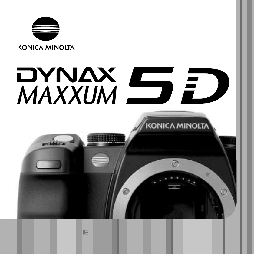
Attach a lens (p. 18) and the camera strap (p. 19).
Adjust the viewfinder diopter if necessary (p. 19).
Charge the battery (p. 20) and insert it into the camera
(p. 21).
Insert a memory card into the camera (p. 24). Turn on
the camera and set the date and time (p 26).
To take a picture, see the basic recording operation section on page 28. To use
the flash, see page 31.
To playback recorded images, see page 34.
To delete an image, see page 36.
To connect the camera to a computer to download images, see page 115.
CAUTION: when using a Windows 98 or 98SE operating system, the supplied
driver software must be installed, see page 116. To install Kodak EasyShare
software, see page 132. To install DiMAGE Master Lite, see page 134.
For basic problems, see the troubleshooting section on page 136.
Page 3

Thank you for purchasing this Konica Minolta digital camera. Please take the time to read
through this instruction manual so you can enjoy all the features of your new camera.
Check the packing list before using this product. If any items are missing, immediately
contact your camera dealer.
3
BEFORE YOU BEGIN
Konica Minolta is a trademark of Konica Minolta Holdings, Inc. Maxxum. Dynax. and DiMAGE are
trademarks of Konica Minolta Photo Imaging, Inc. Apple, Macintosh, and Mac OS are registered
trademarks of Apple Computer Inc. Microsoft and Windows are registered trademarks of the Microsoft
Corporation. The official name of Windows is Microsoft Windows Operating System. Microdrive is a
trademark of Hitachi Global Storage Technologies. Adobe is a registered trademark of Adobe Systems
Incorporated. EasyShare is a registered trademark or trademark of the Eastman Kodak Company in
the United States and other countries. All other brand and product names are trademarks or registered
trademarks of their respective owners.
This product is designed to work with accessories manufactured and distributed by
Konica Minolta. Using accessories or equipment not endorsed by Konica Minolta may
result in unsatisfactory performance or damage to the product and its accessories.
Only use the battery specified in this manual that are manufactured and distributed by
Konica Minolta. Beware of counterfeit batteries; the use of these batteries will damage
the product and may cause fire.
This manual contains information on products and accessories available at the time of
printing. To obtain compatibility information on products not contained in this manual,
contact a Konica Minolta service facility.
Maxxum/Dynax digital camera
Lithium-ion battery NP-400
Lithium-ion battery charger BC-400
Wide Strap WS-5
Video Cable VC-500
USB Cable USB-3
Digital Camera Software CD-ROM
Camera instruction manual
Warranty card
BEFORE YOU BEGIN
Page 4

FOR PROPER AND SAFE USE
4
F
OR PROPER AND SAFE USE
NP-400 LITHIUM-ION BATTERIES
This camera operates on a powerful lithium-ion battery. Misuse or abuse of the lithiumion battery can cause damage or injury through fire, electric shock, or chemical leakage.
Read and understand all warnings before using the battery.
DANGER
• Do not short, disassemble, damage, or modify the battery.
• Do not expose the battery to fire or high temperatures over 60°C (140°F).
• Do not expose the battery to water, or moisture. W ater can corrode or damage the internal battery safety devices and cause the battery to overheat, ignite, rupture, or leak.
• Do not drop or subject the battery to strong impacts. Impacts can damage the internal
battery safety devices and cause the battery to overheat, ignite, rupture, or leak.
• Do not store the battery near or in metallic products.
• Do not use the battery with any other products.
• Only use the specified charger. An inappropriate charger may cause damage or injury
through fire or electric shock.
• Do not use a leaking battery. If fluid from the battery enters your eye, immediately rinse
the eye with plenty of fresh water and contact a doctor. If fluid from the battery makes
contact with your skin or clothing, wash the area thoroughly with water.
• Only use or charge the battery in an environment with ambient temperatures between
0° and 40°C (32° and 104°F). Only store the battery in an environment with ambient
temperatures between –20° and 30°C (–4° and 86°F) and a humidity of 45% to 85%
RH.
WARNING
• Tape over the lithium-ion battery contacts to avoid short-circuiting during disposal;
always follow local regulations for battery disposal.
• If charging is not completed after the specified period elapses, unplug the charger and
discontinue charging immediately.
Page 5

5
GENERAL PRODUCT WARNINGS AND CAUTIONS
WARNING
• Only use the battery specified in this manual.
• Only use the specified charger or AC adapter within the voltage range indicated on the
unit. An inappropriate adapter or current may cause damage or injury through fire or
electric shock.
• Only use the charger power cord in the sales region for which it was designed. An inappropriate current may cause damage or injury through fire or electric shock.
• Do not disassemble the camera or charger. Electric shock may cause injury if a high
voltage circuit inside the product is touched.
• Immediately remove the battery or unplug the AC adapter and discontinue use if the
camera is dropped or subjected to an impact in which the interior, especially the flash
unit, is exposed. The flash has a high voltage circuit which may cause an electric shock
resulting in injury. The continued use of a damaged product or part may cause injuries
or fire.
• Keep the battery, memory card, or small parts that could be swallowed away from
infants. Contact a doctor immediately if an object is swallowed.
• Store this product out of reach of children. Be careful when around children not to harm
them with the product or parts.
• Do not fire the flash directly into the eyes. It may damage eyesight.
• Do not fire the flash at vehicle operators. It may cause a distraction or temporary blindness which may lead to an accident.
• Do not use the monitor while operating a vehicle or walking. It may result in injury or an
accident.
• Do not look at the sun or strong light sources through the viewfinder or lens. It may damage your eyesight or cause blindness.
Read and understand the following warnings and cautions for safe use of the digital
camera and its accessories.
Page 6

6
F
OR PROPER AND SAFE USE
• Do not use these products in a humid environment, or operate them with wet hands. If
liquid enters these products, immediately remove the battery or unplug the product, and
discontinue use. The continued use of a product exposed to liquids may cause damage
or injury through fire or electric shock.
• Do not use these products near inflammable gases or liquids such as gasoline, benzine,
or paint thinner. Do not use inflammable products such as alcohol, benzine, or paint
thinner to clean these products. The use of inflammable cleaners and solvents may
cause an explosion or fire.
• When unplugging the AC adapter or charger, do not pull on the power cord. Hold the
plug when removing it from an outlet.
• Do not damage, twist, modify, heat, or place heavy objects on the AC adapter or charger cord. Adamaged cord may cause damage or injury through fire or electric shock.
• If these products emits a strange odor, heat, or smoke, discontinue use. Immediately
remove the battery taking care not to burn yourself as the battery may become hot with
use. The continued use of a damaged product or part may cause injuries or fire.
• Take the product to a Konica Minolta service facility when repairs are required.
• Handling the cord on this product may expose you to lead, a chemical known to the
State of California to cause cancer, and birth defects or other reproductive harm. Wash
hands after handling.
Page 7

7
CAUTION
• Do not point a photographic lens directly at the sun. If sunlight is focused on an inflammable surface, a fire may result. Replace the lens cap when the lens is not in use.
• Do not use or store these products in a hot or humid environment such as the glove
compartment or trunk of a car. It may damage the camera, charger, and battery which
may result in burns or injuries caused by heat, fire, explosion, or leaking battery fluid.
• If the battery is leaking, discontinue use of the product.
• The camera, charger, and battery temperature rises with extended periods of use. Care
should be taken to avoid burns.
• Burns may result if the memory card or battery is removed immediately after extended
periods of use. Turn the camera off and wait for it to cool.
• Do not fire the flash while it is in contact with people or objects. The flash unit discharges a large amount of energy which may cause burns.
• Do not apply pressure to the LCD monitor. A damaged monitor may cause injury, and
the liquid from the monitor may cause inflammation. If liquid from the monitor makes
contact with skin, wash the area with fresh water. If liquid from the monitor comes in
contact with the eyes, immediately rinse the eyes with plenty of water and contact a
doctor.
• When using the AC adapter and charger, insert the plug securely into the electrical outlet.
• Do not use electronic transformers or travel adapters with the charger. The use of these
devices may cause a fire or damage the product.
• Do not use if the AC adapter or charger cord is damaged.
• Do not cover the AC adapter or charger. Afire may result.
• Do not obstruct access to the AC adapter or charger; this can hinder the unplugging of
the units in emergencies.
• Unplug the AC adapter or charger when cleaning or not in use.
Page 8

8
T
ABLE OF CONTENTS
Quick start check list ........................................................................................................2
Before you begin..............................................................................................................3
For proper and safe use ...................................................................................................4
Names of parts...............................................................................................................14
Camera body .......................................................................................................14
Recording mode display......................................................................................16
Viewfinder............................................................................................................17
Getting up and running..................................................................................................18
Attaching and removing a lens ...........................................................................18
Attaching the camera strap.................................................................................19
Diopter adjustment..............................................................................................19
Charging the battery............................................................................................20
Installing and changing the battery .....................................................................21
Turning on the camera........................................................................................22
AC Adapter AC-1 1 (sold separately) ...................................................................22
Battery condition indicator...................................................................................23
Auto power save..................................................................................................23
Inserting and changing a memory card...............................................................24
Setting the date and time....................................................................................26
Basic recording...............................................................................................................27
Setting the camera to record images automatically............................................27
Handling the camera...........................................................................................27
Basic recording display .......................................................................................27
Basic recording operation....................................................................................28
Focus signals ......................................................................................................29
Special focusing situations..................................................................................29
Focus lock...........................................................................................................30
Camera-shake warning.......................................................................................30
Using the built-in flash .........................................................................................31
Anti-Shake system ..............................................................................................32
Display button......................................................................................................33
Basic playback ...............................................................................................................34
Viewing images...................................................................................................34
Rotating images ..................................................................................................34
TABLE OF CONTENTS
Page 9

9
Histogram display ................................................................................................35
Deleting single images ........................................................................................36
Changing the playback display ...........................................................................37
Enlarged playback ...............................................................................................38
Advanced recording .......................................................................................................39
Exposure-mode dial ............................................................................................39
Digital Subject Programs..........................................................................40
Auto Recording.........................................................................................41
Program - P..............................................................................................41
Aperture priority - A..................................................................................42
Shutter priority - S....................................................................................42
Exposure control range warnings.............................................................43
Manual exposure - M ...............................................................................44
Bulb exposures.........................................................................................45
Exposure lock - AEL button.................................................................................46
Slow sync............................................................................................................47
Spot AF button.....................................................................................................47
Exposure compensation ......................................................................................48
Depth-of-field preview .........................................................................................49
AF / MF switch ....................................................................................................49
Drive modes........................................................................................................50
Continuous-advance notes.......................................................................51
Self-timer notes........................................................................................51
Exposure bracketing notes.......................................................................52
White-balance bracketing notes...............................................................53
Camera sensitivity (ISO) and Zone Matching.....................................................54
Camera sensitivity and flash range.....................................................................55
Function button....................................................................................................56
AF area.....................................................................................................57
AF modes.................................................................................................58
Metering modes........................................................................................59
Flash compensation.................................................................................60
Color mode ...............................................................................................61
Digital Effects Control (DEC)....................................................................63
Page 10

10
T
ABLE OF CONTENTS
White balance......................................................................................................64
Auto white balance...................................................................................64
Preset white balance................................................................................65
Custom white balance..............................................................................66
Color temperature ....................................................................................67
A short guide to photography .........................................................................................68
Light sources and color.......................................................................................69
What is an Ev?....................................................................................................69
Recording menu.............................................................................................................70
Navigating the recording menu...........................................................................70
Image size and image quality..............................................................................72
Instant playback ..................................................................................................74
Noise reduction ...................................................................................................74
Flash modes ........................................................................................................75
Wireless/Remote flash .............................................................................76
Wireless/Remote camera and flash ranges.............................................78
Flash control ........................................................................................................79
Bracketing order..................................................................................................80
Recording mode reset.........................................................................................80
About DiMAGE Master...................................................................................................81
Playback menu...............................................................................................................82
Navigating the playback menu............................................................................82
Frame-selection screen .......................................................................................83
Delete..................................................................................................................84
Format.................................................................................................................85
View folder...........................................................................................................85
Lock ..................................................................................................................86
Index playback format.........................................................................................87
Slide Show ..........................................................................................................88
About DPOF........................................................................................................88
DPOF setup.........................................................................................................89
Date imprint.........................................................................................................90
Index print............................................................................................................90
Cancel print.........................................................................................................90
Opening the custom & setup menus..............................................................................91
Page 11

11
Custom menu.................................................................................................................92
AF / Shutter release priority setup ......................................................................93
Focus-hold button setup......................................................................................94
AEL button setup.................................................................................................94
Control-dial setup................................................................................................95
Exposure-compensation setup ............................................................................95
AF illuminator ......................................................................................................96
Card shutter lock.................................................................................................96
Lens shutter lock.................................................................................................96
AF area setup......................................................................................................97
Monitor display setup ..........................................................................................97
Recording display setup......................................................................................97
Playback display setup........................................................................................97
Setup menu ..................................................................................................................98
LCD brightness..................................................................................................100
Transfer mode...................................................................................................100
Video output......................................................................................................101
Viewing images on a television.........................................................................101
Audio signals.....................................................................................................102
Language...........................................................................................................102
Date and time setup..........................................................................................103
File number (#) memory....................................................................................103
Folder name......................................................................................................104
Select folder ......................................................................................................104
New folder.........................................................................................................105
LCD backlight....................................................................................................105
Auto power save................................................................................................105
Menu section memory.......................................................................................106
Delete confirmation ...........................................................................................106
Clean CCD........................................................................................................106
Reset default.....................................................................................................108
Accessory notes ...........................................................................................................110
Lens compatibility..............................................................................................110
Lens shadowing.................................................................................................110
Focal-length conversion.....................................................................................110
Page 12

12
T
ABLE OF CONTENTS
CCD plane ........................................................................................................110
Attaching the eyepiece cap................................................................................111
Viewfinder accessories......................................................................................111
Attaching a remote cord.....................................................................................111
Attaching an accessory flash.............................................................................112
Flash compatibility.............................................................................................112
High-Speed Sync. (HSS) ...................................................................................112
PD Flash Adapter PCT-100...............................................................................113
About the battery charger cord ..........................................................................113
Data-transfer mode.......................................................................................................114
System requirements.........................................................................................114
Connecting the camera to a computer..............................................................115
Connecting to Windows 98 / 98 second edition................................................116
Automatic installation..............................................................................116
Manual installation..................................................................................117
Auto power save (Data-transfer mode).............................................................119
Memory card folder organization .......................................................................120
Disconnecting the camera from the computer..................................................122
Windows 98 / 98 second edition...........................................................122
Windows Me, 2000 Professional, and XP ..............................................122
Macintosh...............................................................................................123
Changing the memory card (data-transfer mode).............................................124
Windows 98 / 98 second edition...........................................................124
Windows Me, 2000 Professional, and XP ..............................................124
Macintosh...............................................................................................124
Removing the driver software - Windows .........................................................125
PictBridge..........................................................................................................126
Notes on printing errors.....................................................................................127
Navigating the PictBridge menu ........................................................................128
Batch print..............................................................................................129
Index print...............................................................................................129
Paper size ..............................................................................................130
Layout.....................................................................................................130
Print quality.............................................................................................131
Data print ................................................................................................131
DPOF print .............................................................................................131
Page 13

13
Kodak EasyShare software...............................................................................132
DiMAGE Master Lite..........................................................................................134
Troubleshooting............................................................................................................136
Care and storage..........................................................................................................139
Camera care......................................................................................................139
Cleaning ............................................................................................................139
Storage..............................................................................................................139
Operating temperatures and conditions............................................................140
Memory card care and handling........................................................................140
Batteries ............................................................................................................140
LCD monitor care..............................................................................................141
Copyright...........................................................................................................141
Before important events or journeys.................................................................141
Questions and service.......................................................................................141
Technical specifications ................................................................................................144
Index ................................................................................................................146
Page 14
14
N
AMES OF PARTS
* This camera is a sophisticated
optical instrument. Care should be
taken to keep these surfaces clean.
Please read the care and storage
instructions in the back of this
manual (p. 139).
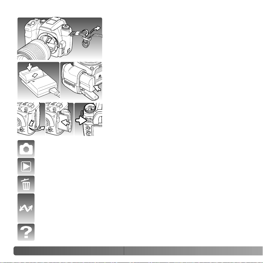
CAMERA BODY
2. Control dial
3. Shutter-release button
5. Flash* (p. 31)
8. Strap eyelet (p. 19)
NAMES OF PARTS
10.Remote-control terminal (p. 111)
11. AF/MF switch (p. 49)
16.Tripod socket
17.Battery-chamber release (p. 21)
6. White-balance dial (p. 64)
4. Exposure-mode dial (p. 39)
1. Self-timer lamp (p. 51)
18.Battery-chamber door (p. 21)
15.Depth-of-field preview button (p. 49)
9. Lens release (p. 18)
13.Mirror*
14.Lens contacts*
12.Lens mount
7. White-balance button (p. 64)
Page 15
15
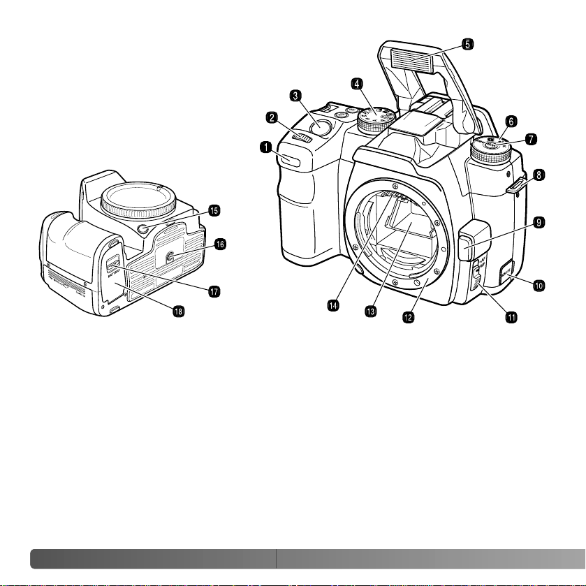
14.Card-slot / USB port / Video-out terminal
door (p. 24, 115, 101)
22.Menu button
17.Controller & Spot-AF button (p. 47)
12.AE lock button (p. 46)
2. Eyepiece sensors*
13.Access lamp
20.Delete button (p. 36)
19.Playback button (p. 34)
21.Display button (p. 33, 37)
15.Anti-Shake switch (p. 32)
3. Viewfinder* (p. 17)
18.LCD monitor* (p. 16)
1. Main switch
6. Diopter-adjustment dial (p. 19)
9. Drive-mode button (p. 50)
10.Camera-sensitivity (ISO) button (p. 54)
5. Accessory shoe 16.DC terminal (p. 22)
8. Exposure-compensation button (p. 48)
4. Eyepiece cup (p. 111)
7. Function button (p. 56)
11. Strap eyelet (p. 19)
Page 16
16
N
AMES OF PARTS
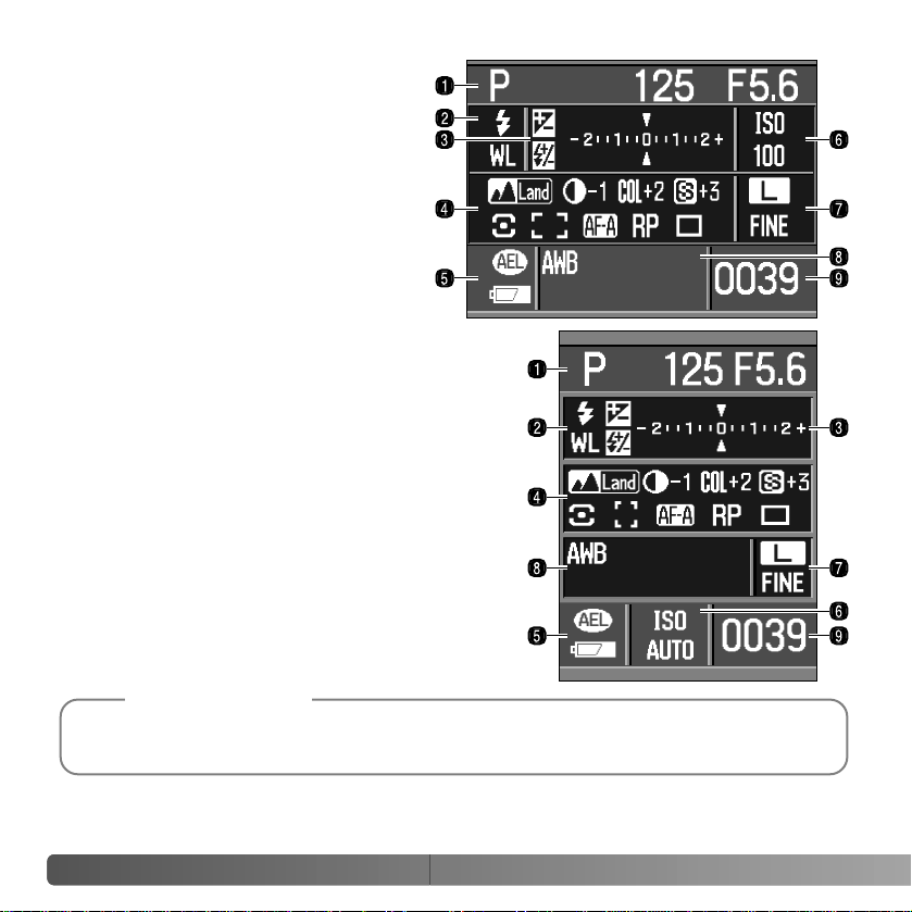
RECORDING MODE DISPLAY
8. White-balance panel
2. Flash panel
5. AE lock / battery condition panel
7. Image size / quality panel
9. Frame counter
4. Color mode / Digital Effects Control / Metering /
AF area / AF mode / Release priority / Drive
mode panel
3. Ev scale
1. Exposure mode / exposure panel
6. Camera-sensitivity / Zone Matching panel
The recording display shows information
on camera operation in panels. The
information displayed varies with the
functions set.
As the camera is rotated to a vertical
position, the display automatically
rotates to compensate for the camera
position.
The monitor-display setup and recording-display setup custom functions in section 2 of the
custom menu control the monitor display (p. 97).
Camera Notes
Page 17
17
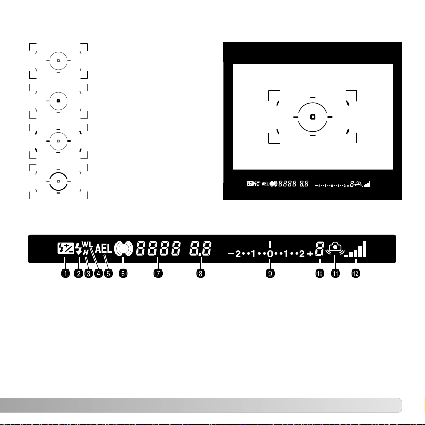
VIEWFINDER
Wide focus frame
Spot-metering area (p. 59)
Spot AF area (p. 47)
Local focus areas (p. 57)
1. Flash-compensation indicator (p. 60)
4. Wireless/Remote flash indicator (p. 76)
5. AE lock indicator (p. 46)
9. Ev scale
8. Aperture display
7. Shutter-speed display
10.Frames-remaining counter
11. Camera-shake warning (p. 30)
3. High-speed sync. indicator (p. 112)
2. Flash signal (p. 31)
12.Anti-Shake scale (p. 32)6. Focus signal (p. 29)
The spot AF area and local focus areas are illuminated briefly to indicate the point of
focus when the focus is locked.
The frames-remaining counter indicates the approximate number of frames that can be
stored in the camera buffer memory while recording. This number changes as images are
captured and saved to the memory card.
Page 18
18
G
ETTING UP AND RUNNING
GETTING UP AND RUNNING
This section covers the preparation of the camera. This includes the changing of
batteries, memory cards, and lenses as well as the use of external power supplies.
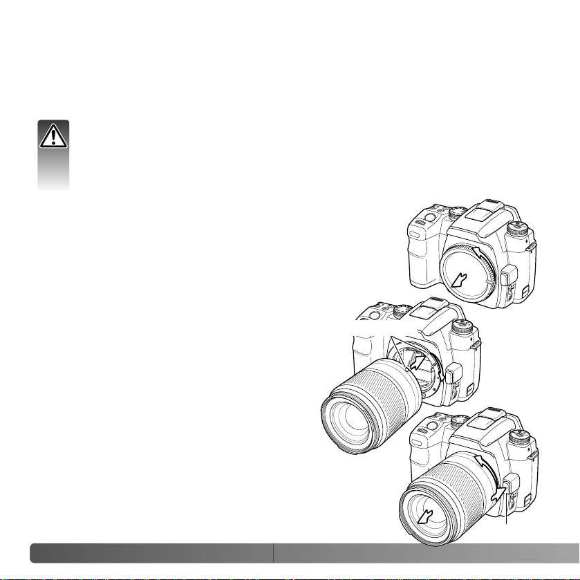
Align the red mounting index on the lens and
camera body. Carefully insert the lens into the
mount, then turn it clockwise until it clicks into
the locked position. Do not insert the lens at an
angle. If it does not fit, check its orientation with
the index marks. Never force the lens.
Press the lens release all the way in and turn the lens counterclockwise until it stops. Carefully remove the lens.
Remove the body cap from the camera and the rear cap from
the lens.
A TTACHING AND REMOVING A LENS
Lens release
This camera uses interchangeable lenses. See page 110 for compatible lenses.
Never touch the inside of the camera, especially the lens contacts and mirror. Do
not leave the interior of the camera exposed to dust or dirt. Replace the caps on
the lens and attach the body cap or another lens to the camera as soon as
possible. Check the body cap or lens is free from dust before mounting.
Mounting indices
Page 19
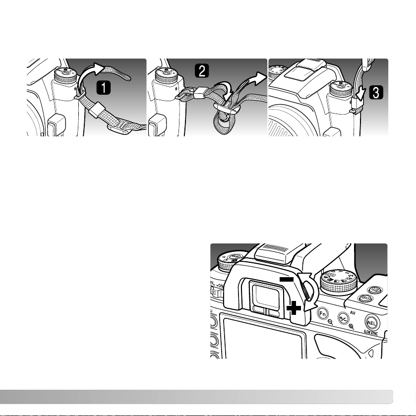
1. Pass the tip of the strap through the camera’s strap eyelet from below. Attach the
strap so the tip comes between the strap and the camera.
2. Thread the tip of the strap through the holder ring and the inside of the buckle and
pull to tighten. Leave some slack in the camera strap so the tip may be threaded
through the buckle easily.
3. Push the holder ring toward the strap eyelet to secure the strap to the camera. Repeat
with the other end of the camera strap.
19
ATTACHING THE CAMERA STRAP
Always keep the camera strap around your neck in the event that you drop the camera.
The viewfinder has a built-in diopter that
can be adjusted between –2.5 to +1.0.
While looking through the viewfinder, turn
the diopter-adjustment dial until the
viewfinder focus frame is sharp.
The optional Eyepiece Corrector 1000
series diopters can be used if the
adjustable viewfinder diopter is not
sufficient.
DIOPTER ADJUSTMENT
Page 20
20
G
ETTING UP AND RUNNING
CHARGING THE BATTERY
Before the camera can be used, the lithium-ion battery must be charged. Before charging
the battery , read the safety warnings on page 4 of this manual. Only recharge the battery
with the supplied battery charger. The battery should be recharged before each shooting
session. See page 140 for battery care and storage.
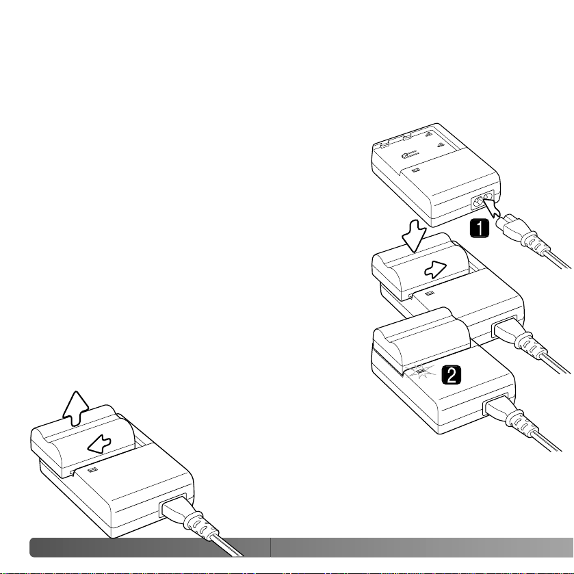
With the battery contacts toward the charger, align the
channels on the bottom of the battery with the tabs on the
charger unit. Slide the battery into the unit.
Plug the power cord into the back of the charger unit (1).
Plug the other end of the cord into a live household outlet.
The included AC cord is designed for the current of the
sales region. Only use the cord in the region it was
purchased. For more on the AC cable, see page 113.
Slide and lift the battery to remove it
from the charger. Unplug the
power cord from the outlet.
The indicator lamp (2) glows to show the battery is
charging. The lamp goes out when the battery is charged.
Charging time is approximately 150 minutes.
Page 21
21
INSTALLING AND CHANGING THE BATTERY
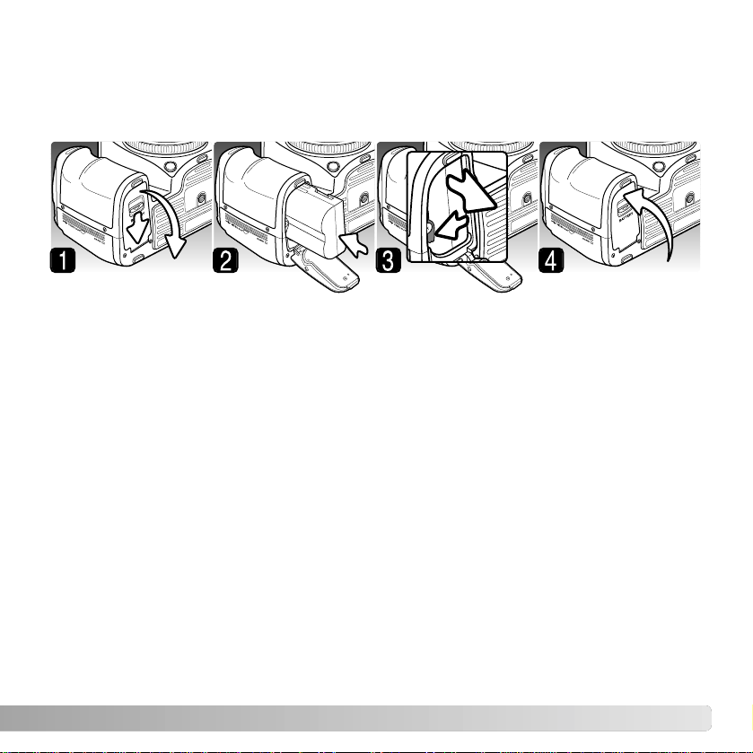
1. Open the battery-chamber door by sliding the battery-chamber release toward the
back of the camera.
2. Insert the battery with the battery contacts first. Push the battery into the chamber
until the battery latch clicks into place.
3. To remove a battery, slide the battery latch to the side of the battery chamber; the
battery springs out.
4. Close the battery-chamber door until it clicks shut.
This digital camera uses one NP-400 lithium-ion battery. Before using the battery, read
the safety warnings on pages 4 of this manual. When replacing batteries, the camera
should be off.
Page 22

22
G
ETTING UP AND RUNNING
AC ADAPTER AC-1 1 (SOLD SEPARATELY)
The AC Adapter AC-11 allows the camera to be powered from an electrical household
outlet. The AC Adapter is recommended when the camera is interfaced with a computer
or during periods of heavy use.
Open the DC terminal cover from the left. The
cover is attached to the body to prevent loss.
Insert the mini plug of the AC adapter into the DC
terminal.
Insert the AC adapter plug into an electrical outlet.
Always turn off the camera and confirm the
access lamp is not lit before changing
between power supplies.
Access lamp
Each time the camera is turned on, it automatically
focuses the lens to the infinity position, even in manual
focus. This operation is necessary to ensure proper
exposures.
Camera Notes
TURNING ON THE CAMERA
Slide the main switch to the on position to turn on
the camera. The access lamp glows briefly to
indicate the power is on. When the camera is
initially turned on, the date and time should be
set, see page 26. When not in use, turn the
camera off to conserve power.
Terminal cover
Page 23
23
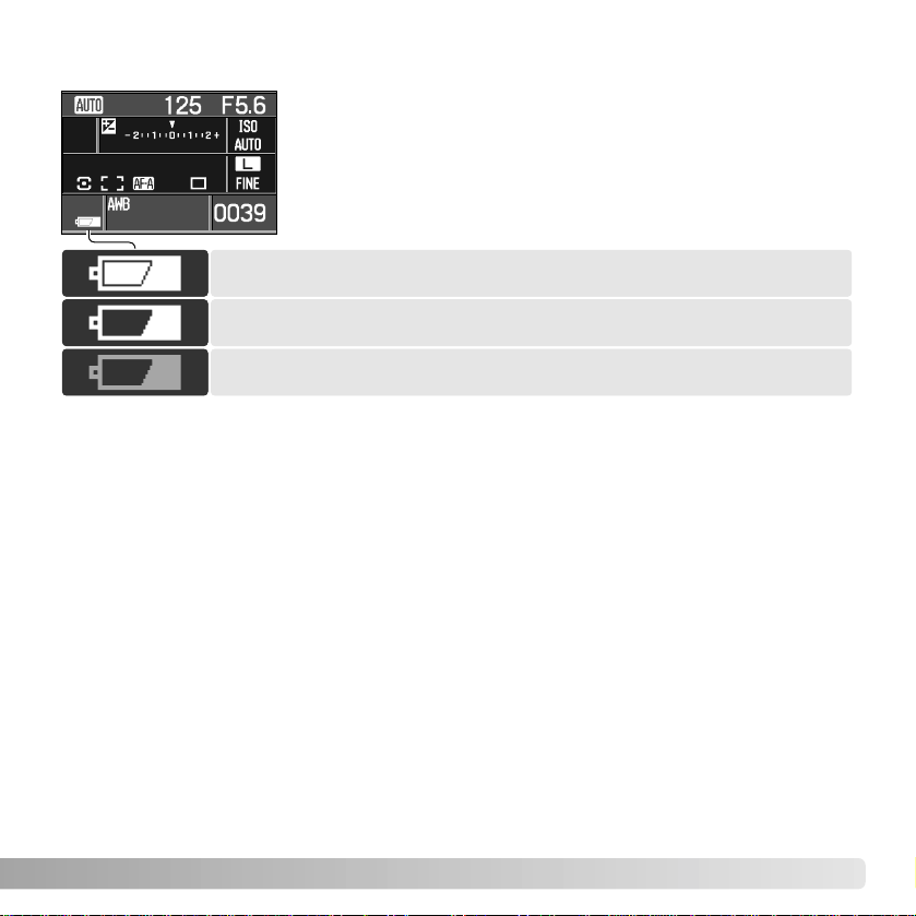
BATTERY CONDITION INDICATOR
Full-battery indicator - the battery is fully charged.
Low-battery indicator - battery power is low. Recharge the battery.
AUTO POWER SAVE
To conserve battery power, the camera shuts down if an operation is not made within
three minutes. To restore power, press the shutter-release button partway down. The
length of the auto-power-save period can be changed in section 3 of the setup menu (p.
105).
The LCD monitor backlight turns off after five seconds. Press a camera button to restore
the display. The length of this period can be changed in section 3 of the setup menu (p.
105).
This camera is equipped with an automatic battery-condition
indicator. When the camera is on, the indicator appears on the
monitor. The indicator changes from white to red when battery
power is low. Not all camera functions are available if battery
power is low. If the monitor is blank, the battery may be
exhausted.
Low-battery warning - battery power is very low. Recharge the
battery.
When power falls below the level of the low-battery warning, the battery exhausted
message appears just before the camera shuts down. The camera will not function until
the battery is recharged.
Page 24
24
G
ETTING UP AND RUNNING
INSERTING AND CHANGING A MEMORY CARD
A memory card must be inserted for the camera to operate. If a card has not been
inserted, “----” is displayed in the frame counter. Type I and II CompactFlash cards and
Microdrives are compatible with this camera.
Always turn off the camera and confirm the access lamp is not lit before inserting
or removing a memory card, otherwise the card may be damaged, and data lost.
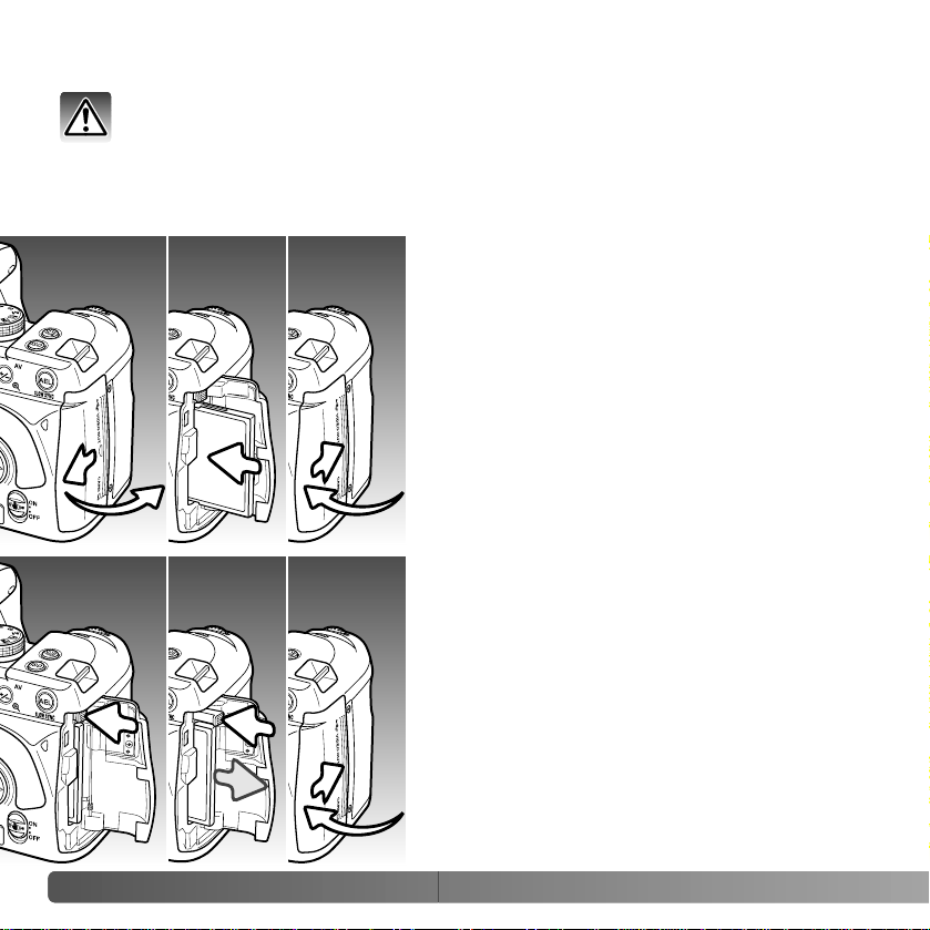
1. Slide the card-slot door toward the back of
the camera to release the safety catch and
open.
2. Insert a memory card all the way into the card
slot. Insert the card so the face is toward the
front of the camera. Always push the card in
straight. Never force the card. If the card does
not fit, check that it is oriented correctly.
3. Close the card-slot door and slide it toward
the front of the camera to engage the safety
catch.
4. To eject a card, open the card-slot door, and
press and release the card-eject lever to
extend it.
5. Press the extended card-eject lever to eject
the card. The card can now be pulled out.
Take care when removing the card as it
becomes hot with use. The card-eject lever
should remain inside the camera body. If it
extends, push it into the camera.
6. Insert a new memory card and close the cardslot door.
123
456
Page 25

25
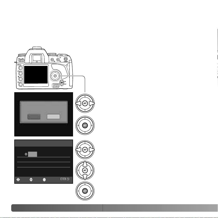
If the “Unable to use card, Format?” message appears, the
card should be formatted with the camera. Use the right/left
keys of the controller to highlight the yes button. Press the
central button of the controller to format the card; this can
take several minutes depending on the card. When a card
is formatted, all the data on the card is permanently erased.
Selecting “No” cancels the formatting operation; remove the
card from the camera. A memory card used in another
camera may have to be formatted before being used.
Unable to use card.
Format?
No
Yes
If the card-error message appears, press the central button of the controller to close the
window; check the Konica Minolta web site for the latest compatibility information:
North America
http://www.konicaminolta.us/
Europe
http://www.konicaminoltasupport.com
Page 26
26
G
ETTING UP AND RUNNING
SETTING THE DATE AND TIME
After initially inserting a memory card and battery, a message opens requesting that
camera’s clock and calendar be set. Images are recorded with the date and time of
capture. Depending on the region, the menu language may also have to be set. To
change the language, see the setup menu section on pages 98 and 102.
Turn on the camera.
Navigating the screen is simple. The up/down
and left/right keys of the controller move the
cursor and change settings. The central button of
the controller sets adjustments.
Use the left and right keys to select the item to be
changed. The last item is the date format.
Press the central button to set the clock and
calendar.
Date/Time setup screen
Use the up and down keys to adjust the item. The
date format can be set among year/month/day.
day/month/year, and month/day/year.
2005 . 10 . 23
13 : 14
Date/Time set
:enter:sel :adj.
YYYY/MM/DD
Set date and time?
No
Yes
Use the left and right controller keys to select
“Yes.” “No” cancels the operation.
Press the central button of the controller to
continue.
Page 27
27
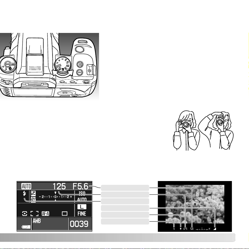
SETTING THE CAMERA TO RECORD IMAGES AUTOMATICALLY
Turn the exposure dial to the auto or program (P)
position. The camera controls are automatic.
Auto acts like the program mode, except that many of
the recording functions are reset each time it is
selected, see page 41 for more information. Not all
function are available in auto recording such as the
color mode and Digital Effects Control. The default
camera sensitivity (p. 54) is auto for auto recording
and ISO 100 for program.
BASIC RECORDING
Grip the camera firmly with your right hand while supporting
the body with the palm of your left hand. Keep your elbows at
your side and your feet shoulder-width apart to hold the
camera steadily. The use of a tripod or monopod is
recommended when using the camera in low-light situations or
when using telephoto lenses.
HANDLING THE CAMERA
BASIC RECORDING DISPLAY
The viewfinder and monitor show the same indicators used in the basic recording
operations.
Aperture
Focus signal
Shutter-speed
Flash indicator
Anti-shake scale
Flash signal
Page 28
28
B
ASIC RECORDING
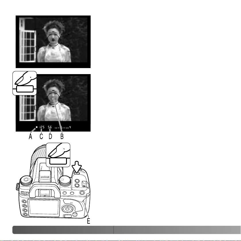
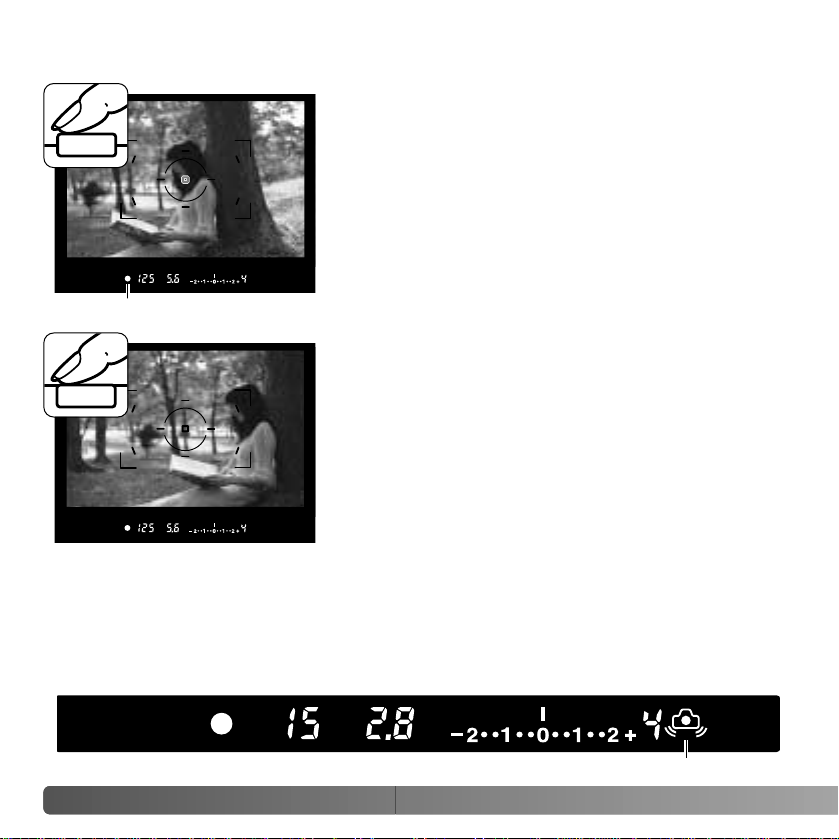
BASIC RECORDING OPERATION
Place the subject within the focus frame. The subject
must be within the focus range of the lens. If using a
zoom lens, change the focal length to frame the
subject.
Press the shutter release button partway down to
activate the autofocus and autoexposure systems (1).
The viewfinder focus signal (A) confirms focus and the
spot or local AF area (B) is illuminated briefly to indicate
the point of focus. If the focus signal blinks, repeat the
procedure.
The shutter speed (C) and aperture (D) used for the
exposure are displayed in the viewfinder and on the
monitor. For information on shutter speeds and ƒnumbers, see pages 43 and 55.
1
2
Press the shutter-release button all the way down (2) to
take the picture. Press the shutter-release button gently
so as not to the shake the camera during the exposure.
The recorded image is displayed while the image is
being saved. Press the shutter-release button partway
down to cancel the playback. For more on instant
playback, see page 74.
The access lamp (E) glows indicating the image data is
being written to the memory card. Never remove a card
while data is being transferred.
Page 29
29
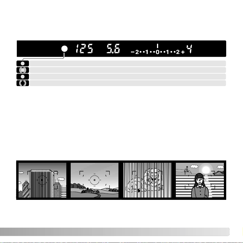
FOCUS SIGNALS
SPECIAL FOCUSING SITUATIONS
The camera may not be able to focus in certain situations. Use focus lock or manual
focus.
The subject in the
focus frame is low in
contrast.
The subject is
composed of repeating
vertical lines.
Two subjects at
different distances
overlap in the focus
frame.
The subject is near a
very bright object or
area.
Focus locked.
The viewfinder focus signal indicates the status of the autofocus system. Focusing time
can be longer with macro or telephoto lenses, or in low-light conditions.
When the camera cannot focus, the subject may be too close or a special focusing
situation may be preventing the system from focusing. Use focus lock with an object at
the same distance as the main subject (p. 30), focus the camera manually (p. 49), or
raise the flash to use the AF illuminator (p. 96).
Autofocus priority and shutter-release priority can be specified in section 1 of the custom
menu (p. 93).
Focus is confirmed (Continuous AF - p. 58).
Focusing (Continuous AF). The shutter is locked.
Indicator blinks - cannot focus. The shutter is locked.
Page 30
30
B
ASIC RECORDING
FOCUS LOCK
The focus-lock function is used when the subject is offcenter and outside the focus frame. Focus lock may
also be used when a special focusing situation
prevents the camera from focusing on the subject.
Place the subject within the focus frame. Press and
hold the shutter-release button partway down (1). The
focus signals indicates that the focus is locked. When
the focus is set, an AF area is illuminated briefly to
indicate the point of focus.
Without lifting your finger from the shutter-release
button, recompose the subject within the viewfinder.
Press the shutter-release button all the way down to
take the picture (2).
1
2
Focus signal
CAMERA-SHAKE WARNING
If the shutter speed falls below the point where the camera can be hand held safely, the
camera-shake warning indicator blinks in the viewfinder. Camera shake is slight blurring
caused by subtle hand motion and is more pronounced with telephoto lenses than wide
angle. Although the warning appears, the shutter can still be released. If the warning
appears, place the camera on a tripod or use the built-in flash.
Camera-shake warning
Page 31

31
If the flash signal does not blink after taking the picture, the subject was not within the
flash range. The flash range depends on the aperture used for the exposure. The follow
chart shows the range when camera sensitivity is set to auto (auto recording) or ISO 100
(program). See page 55 for the flash range with other camera sensitivity settings.
Signal steady - flash charged and ready to fire.
Signal blinking - flash output was sufficient for exposure.
The viewfinder flash signal indicates the status of the flash.
1.0 ~ 4.3m / 3.3 ~ 14.ft.
1.0 ~ 3.4m / 3.3 ~ 11.ft.
1.0 ~ 3.0m / 3.3 ~ 9.8ft.
1.0 ~ 2.1m / 3.3 ~ 6.7ft.
ISO 100 (Program exposure)
f/2.8
f/3.5
f/4.0
f/5.6
Aperture
USING THE BUILT-IN FLASH
To use the flash, simply pull up the unit by the tabs on each
side. The flash position must be set manually, and once up,
the flash unit always fires regardless of the amount of
ambient light. The flash mode is changed with the recording
menu (p. 75).
Push down the built-in flash when the camera is not in use.
The flash is also used as an AF illuminator, see page 96.
The built-in flash is designed to be used with lenses with focal lengths from 18mm or
longer. When using lenses shorter than 18mm, the corners of the image are not be fully
illuminated. The lens hood and certain lenses can cause shadowing, see page 110. The
shutter will not release while the flash is charging.
1.4 ~ 8.6m / 4.6 ~ 28ft.
1.1 ~ 6.8m / 3.6 ~ 22ft.
1.0 ~ 6.0m / 3.3 ~ 20ft.
1.0 ~ 4.3m / 3.3 ~ 14ft.
Auto ISO (Auto recording)
Page 32

32
B
ASIC RECORDING
ANTI-SHAKE SYSTEM
Anti-shake switch
Anti-shake scale
The Anti-Shake system minimizes the affect of camera
shake, a slight blurring caused by subtle hand motion.
Camera shake is more pronounced at long focal lengths
than short ones.
Anti-Shake is less effective with moving subjects or
when the camera is panned, with shutter speeds of 1/4
second or longer, and short object distances. Anti-shake
is disabled with bulb exposures (p. 45).
When the system is active, the Anti-Shake scale in the
viewfinder glows. Anti-Shake isturned off and on with the
Anti-shake switch.
Frame the subject as described in the basic operation
section. Press the shutter-release button partway down
to focus and set the exposure.
The Anti-Shake scale indicates the degree of
stabilization. The greater the scale displayed, the more
unstable the image. Confirm the image has stabilized
with the scale and press the shutter-release button all
the way down to take the picture.
Anti-shake cannot be used with some lenses, see page
1 10. Turn Anti-Shake of f when the camera is mounted on
a tripod. The metered exposure may change when
turning this function on and off.
Page 33

33
DISPLAY BUTTON
Press the display button to switch the
monitor display among full, basic, and off.
For more on the full display, see page 16.
1. Exposure mode (p. 39)
14.Camera-sensitivity display (p. 55)
9. White-balance display (p. 64)
7. AF area display (p. 57)
12.Battery condition indicator (p. 23)
8. Frame counter (p. 73)
4. Image-size display (p. 72)
3. Aperture display 10.Release priority indicator (p. 93)
6. Image-quality display (p. 72)
11. AE lock indicator (p. 46)
5. Exposure/Flash compensation
display (p. 48, 60)
13.Color-mode indicator (p. 61)
The full display uses a scale to show the degree of flash and exposure compensation as
well as the metered exposure value in manual exposure. The basic display uses a
numerical value.
Turning off the display conserves battery power.
Basic
2. Shutter speed display
Page 34

34
B
ASIC PLAYBACK
Images can be viewed in the playback mode. This section covers the basic playback
functions. The playback mode has additional menu functions, see page 82.
BASIC PLAYBACK
The left/right keys of the
controller and the control
dial display the recorded
images.
VIEWING IMAGES
Press the playback
button to activate the
playback mode. To
return to the recording
mode, press the
playback button or the
shutter-release button.
Image size (p. 72)
Image quality (p. 72)
Time of recording
Date of recording
Folder - file number (p. 102)
Frame number / total number of images
ROTATING IMAGES
Press the down key of the controller to rotate a
displayed image 90° left, 90° right, or horizontally.
Page 35

35
To view the histogram of the
displayed image, press the up
key. Press the down key to return
to single-frame playback.
HISTOGRAM DISPLAY
3. Shutter speed
4. Aperture
15.Date of recording
10.Flash compensation (p. 60)
6. Camera sensitivity (ISO) (p. 54)
14.Folder name - file number (p. 120)
9. Exposure compensation (p. 48)
1. Image size (p. 72)
12.Metering mode (p. 59)
11. White-balance mode (p. 64)
5. Exposure mode (p. 39)
2. Image quality (p. 72)
16.Frame number /
Total number of images
Luminance limit display
The dark area of the histogram shows the luminance distribution of the recorded image
from black (left) to white (right). Each one of the 256 vertical lines indicates the relative
proportion of that light value in the image. The histogram can be used to evaluate
exposure and contrast, but displays no color information.
Areas of the image approaching the shadow and highlight
luminance limit are indicated in the image thumbnail. The
portions of the image which levels are close to 0 and 255 flash.
7. Histogram
8. Focal length
13.Anti-Shake
Page 36

36
B
ASIC PLAYBACK
To delete a displayed image, press the
delete button; a confirmation screen
opens.
The displayed image can be deleted. Once
deleted, an image cannot be recovered.
Press the controller to execute the
command on the confirmation screen.
The camera returns to playback mode.
DELETING SINGLE IMAGES
Use the left/right keys to highlight “Yes.”
“No” cancels the operation.
Delete this frame?
Yes No
The camera can play back images on a television set. See page 101 on how to connect the
camera to a TV with the supplied video cable.
Camera Notes
Page 37

37
The display button controls the display format. Each
time the button is pressed, the display cycles through
to the next format: full display, image only, index
playback. The index display can be changed in
section 1 of the playback menu.
Full display Image only
CHANGING THE PLAYBACK DISPLAY
In index playback, the four-way keys of the controller move the yellow border to the
adjacent image. When the image is highlighted with the border, the date of recording, the
lock and printing status, and the frame number of the image are displayed at the bottom
of the screen. The highlighted image can be deleted using the delete button (p. 36).
When the display button is pressed again, the highlighted image is displayed in the
single-frame playback mode. Afour, nine, and sixteen image index can be displayed as
well as a file browser. The index-playback format can be changed in section 1 of the
playback menu (p. 82, 87).
Index playback
Page 38

38
B
ASIC PLAYBACK
Enlarge button
The controller’s four-way keys scroll the
magnified area.
An image can be enlarged
for closer examination. The
maximum magnification
depends on image size
from 2.4X for small images
to 4.7X for large images.
Press the enlarge button to
activate enlarged playback.
The front control dial
browses through the
images.
The magnification area (2) shows the portion of the image
enlarged. The controller’s four-way keys moves the
magnification area. The enlarge and reduce buttons
change the size of the area. Press the playback button to
cancel enlarged playback.
Press the central button of the controller to switch between
displaying the entire image area and the magnified image.
The controller’s four-way keys scrolls the magnified area.
The locator (1) indicates the portion of the image displayed.
The enlarge and reduce buttons change the magnification.
:browse
area
ENLARGED PLAYBACK
Reduce button
:browse
enlarge
Page 39

39
ADVANCED RECORDING
This section contains detailed information on the camera’s recording functions and
operation. Read the sections pertaining to your interest and need.
Manual exposure (p. 44)
Shutter priority (p. 42)
Aperture priority (p. 42)
Program exposure (p. 41)
Auto recording (p. 41) Portrait
The exposure-mode dial is used to select the exposure
modes. Simply turn the exposure dial to the appropriate
position. See the following sections for more information on
these modes. The monitor displays the active exposure
mode.
EXPOSURE-MODE DIAL
Sports Action
Landscape
Exposure mode
Sunset
Night portrait
ADVANCED RECORDING
Digital Subject Programs (p. 40)Exposure control
Page 40

40
A
DVANCED RECORDING
DIGITAL SUBJECT PROGRAMS
Digital subject programs optimize the camera’s exposure,
white-balance, and image-processing systems for specific
conditions and subjects. Simply turn the exposure mode dial to
select the appropriate subject program.
Sports action - used to capture fast action by maximizing shutter speeds. When
using a flash, make sure the subject is within the flash range (p. 55). Continuous
autofocus (p. 58) and continuous-advance drive mode (p. 50) are active. A
monopod is more flexible and compact than a tripod when shooting events.
Sunset - optimized to reproduce rich, warm sunsets. Take care not to look directly
at the sun when it is above the horizon; your eyesight could be damaged
permanently.
Night portrait - for deep, subtle night scenes. When used with flash, the subject
and background exposures are balanced. Use a tripod to eliminate blurring from
camera shake. The flash can only be used with close subjects such as with a
portrait of a person. When using the flash, ask your subjects not to move after the
burst; long shutter speeds can be used for the background exposure.
Not all recording functions, such as the color mode and Digital
Effects Control can be changed when using Digital Subject
Programs. The use of auto white balance (AWB) is
recommended when using Digital Subject Programs (p. 64).
Portrait - optimized to reproduce warm, soft skin tones and a slight defocusing of
the background. Most portraits look best with telephoto lenses; the longer focal
length does not exaggerate facial features and the shallower depth of field softens
the background. Use the built-in flash with strong direct sunlight or backlight to
reduce harsh shadows.
Landscape - optimized to produce sharp, colorful landscapes. Used with bright
outdoor scenery.
Page 41

41
AUTO RECORDING
Auto recording is set with the exposure-mode dial. Use this
exposure mode when wanting fully-automatic exposure
control. Auto recording operates like the program exposure
mode, except that when the exposure mode dial is turned to
the auto-recording position, recording functions are reset to
their default settings. Not all function are available in auto
recording such as color mode and Digital Effects Control.
Functions are reset to: fill-flash or red-eye reduction flash mode, multi-segment metering,
Auto AF focus mode, wide AF area, single-frame advance drive mode, flash and
exposure compensation reset, ADI flash control, Auto ISO, large-size images, fine image
quality, AF priority, noise reduction.
PROGRAM - P
Program exposure is set with the exposure-mode dial (p. 39).
Like auto recording, program controls both the shutter speed
and aperture required for each exposure. The operation is the
same as described in the basic recording operation section on
page 28. However, unlike auto recording, functions set in this
mode do not reset when the position of the exposure-mode dial
is changed. The default camera sensitivity for program is ISO
100.
Program shift
Program shift allows adjustment to the shutter-speed/aperture
combination in 1/3 Ev increments without affecting the total
exposure. Using the built-in flash cancels program shift.
Press the shutter-release button partway down until the shutter
speed and aperture are displayed. Turn the control dial (1) to
shift the shutter speed and aperture combination; P
S is
displayed for the exposure mode. Program shift can be
changed between aperture and shutter priority in section 1 of
the custom menu (p. 92, 95).
Page 42

42
A
DVANCED RECORDING
Shutter priority is set with the exposure-mode dial (p. 39). The
photographer selects the shutter speed and the camera sets
the appropriate aperture to ensure correct exposure.
Turn the control dial (1) to adjust the shutter speed between 30
and 1/4000 second in 1/3 Ev increments. The shutter speed is
displayed on the monitor and in the viewfinder.
Pressing the shutter-release button partway down displays the
corresponding aperture. Press the shutter-release button all
the way down to take the picture.
APERTURE PRIORITY - A
SHUTTER PRIORITY - S
Aperture priority is set with the exposure-mode dial (p. 39). The
photographer selects the aperture and the camera sets the
appropriate shutter speed to ensure correct exposure.
Turn the control dial (1) to adjust the aperture in 1/3 Ev
increments. The aperture range depends on the lens. The
aperture is displayed on the monitor and in the viewfinder.
Pressing the shutter-release button partway down displays the
corresponding shutter speed. With the camera sensitivity (ISO)
set to auto, the shutter speed may not change when the
aperture is adjusted because the shutter speeds can change in
fine steps. Press the shutter-release button all the way down to
take the picture. For information on ƒ-numbers, see page 55.
There is a limit to the maximum shutter speed when using the built-in flash. When Anti-Shake is
on, the maximum shutter speed that can be used is 1/125s. With Anti-Shake off, the flash sync.
speed is 1/160s. While a faster shutter speed cannot be used, there is no limit to the use of slower
shutter speeds. Flash range is dependent on the aperture, see page 55.
Flash Sync. Speed
Page 43

43
The shutter speed used for each exposure is displayed on the monitor and in the viewfinder. The
following notation is used:
The reciprocal is used for shutter speeds from 1/4000 second to 1/3 second. 125 is
1/125 second.
For shutter speeds of a half a second or longer, a quote mark is used to
denote whole seconds. 1”5 is one and a half seconds and 15” is fifteen
seconds.
About Shutter Speeds
If the required exposure is beyond the shutter speed and
aperture range, the shutter speed and aperture displays blink.
In bright conditions, use a neutral density filter on the lens, set
a lower camera sensitivity (ISO), or, if using artificial lights,
reduce the intensity of the illumination. In dark conditions, use
the built-in flash or increase the camera sensitivity (ISO).
If the required exposure is beyond the shutter speed range, the
shutter-speed display blinks. Adjust the aperture until the
display is steady.
If the required exposure is beyond the aperture range, the
aperture display blinks. Adjust the shutter speed until the
display is steady.
EXPOSURE CONTROL RANGE WARNINGS
Auto recording, Program, Digital Subject Programs
Aperture priority
Shutter priority
Page 44

44
A
DVANCED RECORDING
MANUAL EXPOSURE - M
1. Turn the control dial to change the shutter
speed.
2. Press and hold the exposurecompensation button and turn the control
dial to change the aperture.
The operation to change the aperture and
shutter speed can be reversed in section
1 of the custom menu (p. 95).
3. Press and hold the AEL button and turn
the control dial to shift the shutter speed
and aperture without affecting the
exposure.
Manual exposure mode allows individual selection of shutter speeds and apertures. This
mode overrides the exposure system giving the photographer control over the final
exposure. Bulb exposures can be made, see below. Manual exposure is set with the
exposure-mode dial (p. 39).
The set exposure is 1.0Ev less (–) than the exposure determined
by the meter.
The arrow indicates the set exposure is 2.3Ev more (+) or less (–)
than the exposure determined by the meter.
The blinking arrow indicates the set exposure is ±2.7Ev or
greater than the exposure determined by the meter.
The Ev scale on the monitor and in the viewfinder indicates the difference between the
set exposure and the exposure determined by the camera meter. Press the shutterrelease button partway down to activate the meter. The manual metering (M.M.) indicator
is displayed on the monitor Ev scale.
Page 45

45
1. Set the appropriate aperture required for the exposure.
2. Decrease the shutter-speed until “BULB” is displayed.
3. To take the picture, press and hold the shutter-release button for the duration of the
exposure. Releasing the shutter button ends the exposure.
The monitor is blank during the exposure and remains blank after the exposure for up to
30 seconds while noise-reduction processing is applied to the image.
Bulb photographs can be taken in the manual-exposure
mode (M). The use of a tripod, remote cord, and eyepiece
cap (p. 111) is recommended. The camera’s exposure
system cannot be used to calculate bulb exposures. The
use of a separate light meter is recommended. Anti-Shake
is disabled.
BULB EXPOSURES
When using flash with manual exposure, the shutter speed cannot exceed the flash-sync
speed (p. 42). Flash range is dependent on the aperture (p. 55).
By pressing and holding the AEL button (1),
continuous meter readings are displayed on the Ev
scales. Two indices can be displayed. The fixed index
shows the meter reading made when the AELbutton is
pressed. The other index shows any changes in the
metered area.
The fixed index is in reference to the selected metering
mode (p. 59). The other index uses the spot metering
area to determine the reading.
Spot metering area
Page 46

While holding the AELbutton, place the subject in the focus
frame and press the shutter-release button partway down to
focus (2). Press the shutter-release button down all the way
to take the picture.
The exposure remains locked after the picture is taken if the
AEL button is not released.
While the exposure is locked, the camera meter is still
active. The viewfinder and monitor Ev scale shows the
difference between the locked exposure and the current
light level measured with the meter. Spot metering is used.
When the monitor and viewfinder Ev scale indicates 0, the
locked exposure shown in the shutter-speed and aperture
displays is the same as the exposure determined by the
spot-metering area.
46
A
DVANCED RECORDING
EXPOSURE LOCK - AELBUTTON
The AE lock button locks the automatic exposure system without activating the AF
system. This function allows the exposure to be set by a gray card or reference target
outside the scene. When using flash in the auto recording, P, A, or digital subject program
exposure modes, slow-shutter sync is active (p. 47). The operation of the AE lock button
can be changed in section 1 of the custom menu (p. 94).
Frame the exposure target in the viewfinder depending on the metering
mode in use (p. 59). Press and hold the AE lock button (1) to lock the
exposure; the shutter speed and aperture are displayed and the AEL
indicator is displayed in the viewfinder and on the monitor. Release the
button to cancel the lock.
2
Spot metering area
AEL indicator
Ev scale
Page 47

47
When using flash, pressing the AELbutton activates
the slow-sync. function; slow sync. is not available in
S and M exposure modes. Slow sync. balances the
ambient light exposure with the flash exposure so
the background is recorded with the subject.
When the AEL button is pressed and held, the
ambient light exposure is determined and the flash
exposure is based on the locked aperture setting.
The use of a tripod is recommended with slow-sync.
exposures.
SLOW SYNC.
The metered area is 1.0Ev less (–) than the locked exposure.
The arrow indicates the metered exposure is 2.3Ev more (+) or
less (–) than the locked exposure.
The blinking arrow indicates the metered exposure is ±2.7Ev or
greater than the locked exposure.
SPOT-AF BUTTON
Focus
signal
Spot AF
area
Spot AF can be used at any time. With the spot AF
area placed on the subject, press and hold the
central button of the controller to focus (1). The
viewfinder focus signal confirms focus and the spot
AF indicator (2) is displayed on the monitor. Pressing
and holding the four-way controller key activates and
locks focus with the wide focus area.
Compose the image in the viewfinder and press the
shutter-release button all the way down to take the
picture. Focus remains locked after the picture is
taken until the central controller button is released.
Page 48

48
A
DVANCED RECORDING
–2.0Ev–1.0EvMetered camera exposure
The exposure is compensated by -1.0Ev.
EXPOSURE COMPENSATION
When using auto recording, P, A, and S exposure modes or a
digital subject program, the exposure can be compensated.
To compensate the ambient exposure, press and hold the
exposure-compensation button and turn the control dial; the
degree of compensation is displayed on the monitor and
viewfinder Ev scales.
After the setting is made, the shutter-speed and aperture displays indicate the actual
exposure. Because exposure compensation uses 0.3Ev increments, lens apertures may
not be displayed correctly.
Sometimes the camera’s exposure meter is deceived by high key or low key subjects. In
the example below, the dark water caused the camera to overexpose the image making
it bright and washed-out. By compensating the exposure, detail is brought out in the
leaves, and the stones and water appear richer.
Page 49

49
AF / MF SWITCH
Slide the AM/MF switch to change between
autofocus and manual focus. An indicator on the
monitor shows the active focus mode.
DEPTH-OF-FIELD PREVIEW
The aperture controls depth of field; the area in
front of the camera that appears in focus. The
smaller the aperture, the greater the depth of
field. Depth-of-field preview sets the lens
aperture to the setting used in the exposure so
the affect of depth of field can be seen in the
viewfinder.
Press the shutter-release button partway down
to lock the focus and exposure. Press the
depth-of-field preview button to stop down the
aperture.
Some Konica Minolta lenses are equipped with focus-hold buttons. Section 1 in the custom menu
allows the focus-hold button to be used for depth-of-field preview (p. 94).
Camera Notes
Manual focus indicator
Page 50

50
A
DVANCED RECORDING
Single-frame and Continuous advance - to take
single or multiple images at one time (p. 51).
Self-timer - to delay the release of the shutter
by 10 or 2 seconds (p. 51).
The drive modes control the rate and
method of image capture. Single-frame
advance is the default drive mode and
is described in the basic recording
section on page 28. The drive mode is
set with the drive-mode selection
screen. Press the drive-mode button (1)
to open the screen.
DRIVE MODES
Drive-mode indicator
Exposure bracketing - to take a series of 3
images with differing exposure (p. 52).
White-balance bracketing - to make 3 images
with differing white balance (p. 53) from a single
exposure.
Options
Use the up/down keys of the controller to select the drive-mode group.
Use the left/right keys of the controller to highlight the drive-mode option.
Press the center button of the controller to select the drive mode. An indicator
is displayed on the monitor to confirm the selection.
Drive modes
Single-frame adv.
:func. :select :enter
Page 51

51
Continuous-advance mode allows a series of images to be captured while holding down
the shutter-release button. The maximum frame rate is 3fps until the camera buffer
memory is full. The frame rate after that depends on the writing speed of the memory
card. Five RAW or three RAW + JPEG will fill the camera buffer memory. The number of
JPEG images depend on the subject; some subjects can be compressed further than
others.
AF Zoom xi and Power Zoom lenses cannot be zoomed when taking pictures with
continuous advance. The frame rate is affected by the flash as it must recharge between
exposures. Focus and exposure are set between each frame with continuous AF and
Auto AF.
CONTINUOUS-ADVANCE NOTES
SELF-TIMER NOTES
With the camera on a tripod, compose the picture as described in the basic recording
section (p. 28). Press the shutter-release button partway down to lock the exposure and
focus. Press the shutter-release button all the way down to begin the countdown.
Because focus and exposure are determined when the shutter-release button is pressed,
do not stand in front of the camera when taking a self-timer image. Always confirm the
focus with the focus signals before beginning the countdown. Attach the eyepiece cap if
a bright light source is behind the camera, see page 111.
With the ten-second self-timer, the self-timer lamp on the front of the
camera and the audio signals indicate the countdown.The lamp glows
steadily just before the shutter fires. To stop the countdown, change
the position of the exposure-mode dial or flash (lift it or push it down),
or turn the camera off. The audio signal can be turned off in section 1
of the setup menu (p. 98). The mirror raises just before the exposure.
With the two-second self-timer, no indication is given during the countdown. The mirror
raises when the countdown starts.
Page 52

52
A
DVANCED RECORDING
EXPOSURE BRACKETING NOTES
Bracketing is a method of taking a series of images of a static subject in which each
image has a slight variation in exposure. Exposure and flash brackets can be made.
0.3 Ev bracket 0.7 Ev bracketFlash bracket: 0.7 Ev
Exposure bracket: 0.3 Ev
Select continuous-advance bracketing or single-frame advance bracketing and the
bracketing increment with the drive-mode selection screen (p. 50). Continuous-advance
bracketing creates a successive series of three images automatically when the shutterrelease button is pressed and held. The shutter-release button must be pressed for each
exposure when using single-frame advance bracketing. The greater the increment, the
greater the difference among the images. When selected, the number of frames and the
bracketing increment is displayed on the Ev scale. The bracketing order can be set in
section 2 of the recording menu (p. 80).
Continuous-advance bracketing
Single-frame advance bracketingBracketing indicator
Bracketing increment in Ev (p. 69)
To make a flash bracket, raise the camera flash; the ambient exposure is not bracketed.
Only single-frame advance flash brackets can be made regardless of the specified mode;
press the shutter-release button for each exposure. The built-in flash recharges between
exposures. Exposure brackets are made when the flash is down.
Under
Over
Normal
Page 53

Compose the picture as described in the basic recording section (p. 28). As the bracket
is made, the index marks disappear from the Ev scale to show the remaining frames.
When making a continuous-advance bracket, if the shutter button is release before the
bracket is completed, the bracket resets. If using continuous AF or Auto AF with moving
subjects (p. 58), the camera focuses between each exposure.
When exposure brackets are made in S exposure mode, the aperture controls the
bracket. In Aand M exposure modes, the shutter speed controls the bracket; in M mode,
pressing the AELbutton during the bracket changes the exposure control to the aperture.
The camera uses both the aperture and shutter speed control the bracket in P and auto
recording.
53
WHITE-BALANCING BRACKETING NOTES
White-balance bracketing creates three images from a single exposure in which each
image has a slight variation in color temperature. For more on white balance, see page
64.
Select the appropriate white-balance bracketing drive mode with the drive-mode
selection screen (p. 50). The low white-balance bracket uses an approximate 10 mired
shift from the normal balance. The high white-balance bracket uses an approximate 20
mired shift from the normal balance.
Compose and take the picture as described in the basic recording section (p. 28). When
the exposure is made, the camera automatically creates two other images with the
appropriate shift in white balance.
Low white-balance bracket High white-balance bracket
Page 54

54
A
DVANCED RECORDING
Camera sensitivity can be changed.
Zone Matching for high-key or low-key
subjects can be activated. The
sensitivity setting is displayed on the
monitor. Press the camera-sensitivity
button (1) to open the setting screen.
CAMERA SENSITIVITY (ISO) AND ZONE MATCHING
Camera sensitivity display
Use the four-way keys of the controller
to highlight the sensitivity option. The Hi
200 and Lo 80 options are for Zone
Matching, see below.
Press the center button of the controller
to complete the operation.
Sensitivity / Zone Matching
:select :enter
The auto setting automatically adjusts the camera sensitivity to the light conditions
between ISO 100 and 800, and ISO 100 and 400 when using flash. The fixed numerical
settings are based on the film ISO equivalent: the higher the number, the more sensitive.
As the ISO value doubles, the camera sensitivity doubles; a change of one Ev. Noise
increases with sensitivity; an ISO setting of 100 has the least noise and 3200 has the
most. Noise is a grainy texture that can be apparent in the image.
Zone Matching is used for recording high-key (Hi200) or low-key (Low80) scenes. The
number refers to the approximate ISO equivalent for reflected-light meter measurements.
A high-key scene is made up of predominately light tones and colors. A low-key scene is
made up of dark tones and colors. Zone Matching controls exposure and contrast to
improve reproduction of these scenes. When selected, the zone indicator is displayed in
the camera-sensitivity display on the monitor. Any changes to contrast with the Digital
Effects Control are canceled (p. 63).
Page 55

An ƒ-number indicates the relative aperture of the lens and lets us
determine how much light it lets through. But why does the number get
bigger when the amount of light decreases? The answer is in the way
it is written, ƒ/2.0, ƒ/8.0. etc. That means the focal length of the lens (ƒ)
divide by 2 or 8. So a 100mm lens at ƒ/2 has a 50mm physical aperture
(100/2) and at ƒ/8, a 12.5mm physical aperture (100/8). So the fnumber indicates the size of the aperture as a fraction of the focal
length of the lens.
The ƒ-number series was carefully chosen to make controlling
exposures easy. In the chart, the aperture and shutter speed
combinations give the exact same exposure. Notice how the shutter
speed changes to compensate for the change in aperture.
55
CAMERA SENSITIVITY AND FLASH RANGE
ƒ/2.8ISO setting
100
400 / AUTO
800
1600
1.0 ~ 4.3m / 3.3 ~ 14ft.
1.0 ~ 6.0m / 3.3 ~ 20ft.
2.0 ~ 12m / 6.6 ~ 39ft.
2.8 ~ 17m / 9.2 ~ 56ft.
ƒ/5.6ƒ/4.0
3200
4.0 ~ 24m / 13 ~ 79ft.
1.0 ~ 3.0m / 3.3 ~ 9.8ft.
1.0 ~ 4.3m / 3.3 ~ 14ft.
1.0 ~ 6.0m / 3.3 ~ 20ft.
1.4 ~ 8.6m / 4.6 ~ 28ft.
2.0 ~ 12m / 6.6 ~ 39ft.
2.8 ~ 17m / 9.2 ~ 56ft.
1.0 ~ 2.1m / 3.3 ~ 6.7ft.
1.0 ~ 3.0m / 3.3 ~ 9.8ft.
1.0 ~ 4.3m / 3.3 ~ 14ft.
1.0 ~ 6.0m / 3.3 ~ 20ft.
1.4 ~ 8.6m / 4.6 ~ 28ft.
2.0 ~ 12m / 6.6 ~ 39ft.
Achange in camera sensitivity (ISO) affects the flash range. The flash range depends on
the aperture used:
Low80
1.0 ~ 3.8m / 3.3 ~ 12ft.
1.0 ~ 2.7m / 3.3 ~ 8.9ft. 1.0 ~ 1.9m / 3.3 ~ 6.2ft.
200 / Hi200
1.4 ~ 8.6m / 4.6 ~ 28ft.
What is an ƒ-number?
f/2.8 1/2000s
f/4.0 1/1000s
f/5.6 1/500s
f/8.0 1/250s
f/11 1/125s
f/16 1/60s
f/22 1/30s
f/32 1/15s
Page 56

56
A
DVANCED RECORDING
AF area, focus mode, metering mode,
flash compensation, color mode, and
Digital Effects Control are set with the
function button. Monitor indicators show
active settings. Press the button (1) to
open the setting screen.
FUNCTION BUTTON
Function indicators
Options
Use the up/down keys of the controller
to select the function.
Use the left/right keys of the controller
to highlight the option or adjust the
setting.
Press the center button of the controller
to complete the operation.
AF area
Wide AF area
:func. :select :enter
Functions
1. AF area (p. 57)
2. AF mode (p. 58)
3. Metering mode (p. 59)
4. Flash compensation (p. 60)
6. Digital Effects Control (p. 63)
5. Color mode (p. 61)
:func. :select :enter :func. :select :enter :func. :select :enter :func. :adjust :enter :func. :select :enter :func. :adjust :enter
AF area
AF mode Metering mode Flash compensation Color / DEC Color / DEC
Wide AF area Automatic AF Multi-segment ±0.0
See the following sections for more on each
function. The color mode and Digital Effects Control
cannot be set when using auto recording or a digital
subject program. Flash compensation is only
displayed when the flash is raised.
Natural Saturation
Page 57

57
AF AREA
AF-area modes control which AF areas are used for focus. The
modes are selected with the function button (p. 56). The active
AF area is indicated on the monitor.
Wide AF area - to use the wide focus frames in the viewfinder to focus.
See the basic operation section on page 28. Pressing and holding the fourway controller keys also activates and locks focus with the wide focus area.
Spot AF can be used, see page 47.
Spot AF area - the spot AF area is used for focus.
The shutter release button and all controller keys
active spot AF.
Focus area selection - a specific AF area can be
selected. Only the spot AF area can be used with
the AF Reflex 500mm f/8 and AF Power Zoom 3580mm f/4.0-5.6 lenses.
Spot AF area
When focus-focus area selection is active, use the controller to select the
AF area; autofocus activates and locks each time an area is selected. The
central button selects the spot AF area. Focus remains locked after the
picture is taken until the controller is released.
The active area is
indicated on the monitor
and is briefly illuminated
in the viewfinder.
Page 58

58
A
DVANCED RECORDING
AF MODES
Single-shot AF (Autofocus), continuous AF,
automatic AF, and direct manual focusis set with the
function button (p. 56).
The AF system activates when the shutter-release
button is pressed partway down or with the controller
(p. 57). Focus is confirmed with the viewfinder focus
signals, see page 29.
Single-shot AF - a general purpose autofocusing mode. Its operation is
described in the basic recording section. Focus lock is available (p. 30).
Continuous AF - used for photographing moving subjects. The camera
continuously focuses on the subject even when the shutter-release button is
pressed partway down. Spot and local AF areas illuminate as the subject moves
through the wide focus frames to indicate the point of focus when the continuous
AF is active. Focus lock is not available.
Direct manual focus - operates like automatic AF, but after the AF system
focuses, the focus can be adjusted manually by the photographer. Press the
shutter-release button partway down or press the controller to activate the AF
system. When the viewfinder focus signal is displayed, manually focus the lens.
Do not attempt to focus the lens until the focus signal is displayed.
Automatic AF - this AF mode automatically switches between single-shot AF
and continuous AF depending on the subject’s motion.
AF mode
Automatic AF
:func. :select :enter
The active mode is displayed on the monitor.
Page 59

59
METERING MODES
The metering mode specifies the metering pattern.
The metering mode is set with the function button (p.
56).
On the function-selection screen, use the up/down
keys of the controller to select the metering modes
and the left/right keys to select the specific mode.
Press the central button of the controller to complete
the operation.
Spot - uses a circular area within the image to
calculate the exposure. Spot metering allows precise
exposure measurements of a particular object without
being influenced by extremely bright or dark areas
within the scene.
Center weighted - measures light values over the entire image area with
emphasis given the central region.
Spot metering area
Multi-segment metering - the camera’s standard metering mode appropriate
for most photographic situations. By combining information on the subject’s
distance and position from the autofocus system, this mode is less influenced
by spot lighting or backlighting.
Metering mode
Multi-segment
:func. :select :enter
The active mode is displayed on the monitor.
If the luminance levels of the scene are outside the metering
range, both arrows at each end of the Ev scale blink. In dark
conditions, use the camera flash. Under bright light, use a
neutral density filter on the lens to control the light levels.
Page 60

60
A
DVANCED RECORDING
Positive compensation No compensation Negative compensation No flash
FLASH COMPENSATION
The relative output of the flash can be compensated
by ±2.0 Ev with the function button (p. 56).
On the function-selection screen, use the up/down
keys of the controller to select exposure
compensation and the left/right keys to adjust the
degree of compensation. Press the central button of
the controller to complete the operation.
Flash compensation
±0.0 Ev
:func. :adjust :enter
When the camera flash is raised, the degree of flash
compensation is indicated by the Ev scale.
When using fill-flash to reduce harsh shadows
caused by bright illumination or direct sunlight, flash
compensation can change the ratio between the
highlights and shadows. Fill flash affect the darkness
of the shadows without affecting the area illuminated
by the main light source.
–1.0 Ev flash compensation
By decreasing the flash output with a negative Ev setting, the shadows receive less light
and are darker, but subtle details in the shadows that would not appear without the flash
are apparent. Increasing the flash output by using a positive Ev setting softens and nearly
eliminate shadows.
Page 61

61
COLOR MODE
The color mode controls what the image looks like
as well as the color space. The color mode is set
with the function button (p. 56). The color mode can
only be selected in P, A, S, and M exposure modes.
Except for the Abobe RGB and embed Adobe RGB,
all color modes use sRGB color space. Some color
modes use preset Digital Effects Control values (p.
63); the default positions are indicated by a thick
index mark on the scale of the setting screen.
Natural Color - reproduces the colors in the scene faithfully.
Natural Plus - increases contrast and acutance.
Embedded Adobe RGB - natural color reproduction using the extended gamut
Adobe RGB color space. The color space is embedded in the image data.
Color / DEC
:func. :select :enter
Adobe RGB - natural color reproduction using the extended gamut Adobe RGB
color space. The color space is not embedded in the image data.
Black & White - for monochrome images.
Landscape - optimize for daytime outdoor scenery.
Portrait - optimize for the reproduction of skin tones.
Night view - optimize for nighttime scenery without flash.
Night portrait - optimize for nighttime portraits with flash.
Sunset - optimize for landscapes at dusk and dawn. The use of auto white
balance is recommended.
(Continued on the next page.)
Natural
Page 62

62
A
DVANCED RECORDING
Adobe RGB has a larger color gamut than the more common sRGB. The size of the
gamut limits the colors that can be reproduced; the larger the gamut, the more colors. If
the image will be printed out with a high-quality printer, the use of the Embedded Adobe
RGB and Adobe RGB color modes are recommended over the other sRGB color modes.
Embedded Adobe RGB image files are indicated with a .JPE extension. Adobe RGB
images without an embedded profile use a file name beginning with _ICT. See page 120
for more information.
Always use DFC 2.0 optional color space compliant software to open Adobe RGB images
without embedded profiles. DiMAGE Master Lite 1.0.1 or DiMAGE Master 1.1 or later is
DFC 2.0 optional color space compliant. Always use software with color matching or color
management functions to open Adobe RGB images with embedded profiles. Software
without color management functions, such as Kodak EasyShare, will not reproduce
Adobe RGB images correctly.
DiMAGE Master Lite supplied with the camera is required to open RAW Adobe RGB
images taken with this camera. The full version of DiMAGE Master can also be used. For
more on DiMAGE Master, see page 81 or visit us on the web at:
North America
http://kmpi.konicaminolta.us/
Europe
http://www.konicaminoltasupport.com
About Adobe RGB
The active mode is displayed on the monitor. When using
portrait, landscape, sunset, night view, or night portrait color
mode, the use of auto white balance is recommended.
Page 63

63
DIGITAL EFFECTS CONTROL (DEC)
The Digital Effects Control can make adjustments to
the contrast, color saturation, and sharpness of
specific color modes. Some color modes use preset
Digital Effects Control values, the default positions
are indicated by a thick index mark on the scale.
Digital effects are set with the function button (p. 56).
On the function-selection screen, use the up/down
keys of the controller to select the contrast,
saturation, or sharpness control; the selected control
is highlighted. Use the left/right keys to make
adjustments. Press the central button of the
controller to complete the operation.
Color / DEC
:func. :adjust :enter
Sharpness
Color saturation
Contrast
Contrast: -2 Contrast: +2
Sharpness: -2 Sharpness: +2Normal
When set to any value other than zero, an indicator and value
is displayed on the monitor as a warning. The Digital Effects
Control can only be used in P, A, S, and M exposure modes.
Changes in sharpness may
not be apparent on the
camera monitor.
Saturation
Page 64

64
A
DVANCED RECORDING
WHITE BALANCE
White balance is the camera’s ability to make different types of
lighting appear natural. The active white-balance mode is
displayed in the white-balance panel on the monitor.
Auto white balance - white balance is set automatically.
Turn the white-balance dial to the appropriate position.
Preset white balance - to set the white balance to a specific light source.
Custom white balance - to calibrate the camera to a specific lighting situation.
Color temperature - to set the white balance to a specific color temperature.
Auto white balance automatically detects the type of light and
adjust the white balance accordingly. When the built-in flash is
used, the white balance is set for the color temperature of the
flash. Simply set the white-balance dial to the AWB position.
AWB - AUTO WHITE BALANCE
The last changes made are displayed on the monitor. Press the white-balance button in
the center of the dial to change settings. See the following sections for more information.
If the exposure-mode dial is turned to the auto recording or a digital subject program
position, white balances is reset to auto.
Page 65

65
With the white balance dial in the preset white
balance position, press the white-balance button to
open the setting screen.
PRESET WHITE BALANCE
Preset white balance
:select :adjust :enter
Daylight
The up/down controller keys adjust the white balance in seven levels: +3 to –3 (+4 to –2
for fluorescent). Except for fluorescent, the change of one unit is approximately equal to
a 10 mired shift.
Use the left/right controller keys or control
dial to select the white-balance setting.
The up/down controller keys shift the whitebalance, see below.
Press the central controller button to
complete the operation.
For more information on light sources, see page 69.
Daylight - for outdoor sunlit subjects.
Shade - for subjects illuminated by skylight: shady conditions on a clear day.
Cloudy - for cloudy or overcast outdoor conditions.
Flash - for electronic flash.
Tungsten - for incandescent lighting: household filament light bulbs.
Fluorescent - for fluorescent lighting: office ceiling lights.
Page 66

66
A
DVANCED RECORDING
Custom-white-balance function allows the camera to be
calibrated to a specific lighting condition. With the white
balance dial in the custom position, press the whitebalance button to open the setting screen.
CUSTOM WHITE BALANCE
Fill the spot metering area with a white or neutral object;
the object does not need to be in focus. Press the
shutter-release button all the way down to calibrate the
camera.
An image of the reference target is displayed. Press the
central button of the controller to complete the
operation.
A guidance message appears. If the shutter-release
button is pressed partway down, the monitor display
returns. The red custom set indicator is displayed in the
white-balance panel. Turn the white-balance dial to
another position to cancel the routine.
Custom white balance
Use spot metering area.
Press shutter to calibrate.
Spot metering area
Custom white balance
:OK
Page 67

67
A calibration error may occur under extremely bright light sources, especially with flash
units. If an error occurs, a message appears on the monitor and the white-balance
indicator is yellow. Repeat the procedure by recalibrating using a gray card as a
reference target to reduce the intensity of the illumination.
White balance can be set to a known color temperature
of a light source or set to the color temperature
determined by a color meter. With the white balance dial
in the color temperature (K) position, press the whitebalance button to open the setting screen.
COLOR TEMPERATURE
Color temperature
:adjust :enter
:select
Magenta/Green compensation
Color temperature
Use the left/right controller keys or control dial
to select among thousand° K, hundred° K, and
magenta/green compensation.
Use the up/down controller keys to adjust the
value.
Press the central controller button to complete
the operation.
Color temperature refers to the color of the light emitted from a blackbody radiator at a
specific temperature given in degrees Kelvin. This is an accurate way of measuring light
from continuous-spectrum sources such as the sun and incandescent or tungsten light
bulbs.
However, color temperature alone can be inaccurate with discontinuous-spectrum
sources such as fluorescent. The magenta/green compensation scale allows
adjustments to compensate for this problem. The increment on the scale is equivalent to
approximately 5CC; M3 would be 15CC magenta.
For information on light sources, see page 69.
Page 68

68
A
SHORT GUIDE TO PHOTOGRAPHY
Photography can be a rewarding pursuit. It is a broad and disciplined field that can take
years to master. But the pleasure in making photographs and the joy of capturing a
magical moment cannot be compared. The guide is an introduction to some basic
photographic principles.
A SHORT GUIDE TO PHOTOGRAPHY
The lens aperture controls not only exposure, but also
depth of field; the area between the closest object in focus
and the furthest object in focus. The larger the aperture
value, the greater the depth of field and the longer the
shutter speed needed to make the exposure. The smaller
the aperture value, the shallower the depth of field and the
faster the shutter speed needed to make the exposure.
Usually landscape photographs use a large depth of field
(large aperture value) to keep the foreground and
background in focus, and portraits use a shallow depth of
field (small aperture value) to separate the subject from the
background.
Depth of field also changes with focal length. The smaller
the focal length, the greater the depth of field; the longer
the focal length, the shallower the depth of field.
The shutter controls not only exposure, but also the ability
to stop motion. Fast shutter speeds are used in sport
photography to stop action. Slow shutter speeds can be
used to show the flow of motion such as water cascading
over a waterfall. The use of a tripod is recommended with
slow shutter speeds.
For critical work, take a test photograph and view the result
in playback. The image can be deleted if not acceptable
Page 69

69
LIGHT SOURCES AND COLOR
The human eye adapts itself extremely well under different conditions. The paper of this
manual you are reading looks white regardless of the type of lighting. Photographic
systems are much less flexible. As the light source changes, so does the overall color of
a scene - fluorescent office ceiling lights create a green cast to pictures, regular
household tungsten light bulbs make everything red. Like your eyes, the camera’s whitebalance controls adjust for different lighting to make natural looking pictures.
The most common source of light, our sun, changes color depending on the time of day
and the atmospheric conditions. The sun is of course very warm near the horizon and
very blue at noon. The daylight preset white-balance setting is for beautiful sunny days.
When the weather is overcast, the color is cooler and the cloudy setting is appropriate.
When the main light source is skylight, light from the blue sky rather than the direct light
of the sun, the resulting color is very blue. The shade preset white-balance is designed
for this condition.
Artificial lighting is more consistent but shows variations. Tungsten lamps become
warmer as their wattage decreases. And fluorescent lamps come in classifications that
define their color. The preset white balance settings can be adjusted to match the change
in these light sources.
Some artificial lighting have a discontinuous spectrum that create very unnatural color in
a photograph. White balance cannot correct high-energy vapor lighting: sodium-vapor
(yellow highway lights), or mercury vapor. For portraits under these lighting conditions,
the flash can be used to overpower the ambient light. With landscapes containing these
types of lights, set the white balance to the preset daylight setting.
+2.0 Ev
+1.0 Ev
±0.0 Ev
–1.0 Ev
–2.0 Ev
4X as much light
2X as much light
1/2 as much light
1/4 as much light
Calculated exposure
WHA T IS AN EV?
Ev stands for exposure value. A
change of one Ev adjusts the
exposure calculated by the camera
by a factor of two.An Ev and a “stop”
are the same.
Page 70

Use the left/right keys of the controller to highlight the
appropriate menu tab; the menus change as the tabs are
highlighted.
70 R
ECORDING MENU
In recording mode, press the menu button to open and close the menu. The four-way
keys of the controller move the cursor in the menu. Pressing the central button of the
controller enters a setting.
When the required menu section is displayed, use the up/down key to scroll
through the menu options. Highlight the option whose setting needs to be
changed.
Press the right controller key to display the settings; the current setting is
indicated by an arrow. To return to the menu options, press the left key.
Use the up/down key to highlight the new setting. If “Enter” is displayed, press
the central button of the controller to open the next screen.
Press the central button of the controller to select the highlighted setting.
Once a setting has been selected, the cursor returns to the menu options and the new
setting is displayed. Changes can continue to be made. To return to the recording mode,
press the menu button.
NAVIGATING THE RECORDING MENU
Activate the recording menu with the menu button. Tab 1
at the top of the menu is highlighted.
RECORDING MENU
Page 71

The control dial moves the cursor left and right in the
menus.
The menu section memory option in section 3 of the setup
menu memorizes the last menu section opened and returns
to that section when the menu button is pressed (p. 106).
Camera Notes
Flash mode Fill-flash
Flash control ADI flash
–Reset
Bracket order
Image size L: 3008x2000
Quality Fine
Inst.Playback 2 sec.
Noise reductn On
71
To set image resolution (p. 72).
To set file type and compression (p. 72).
To set the flash mode of the built-in flash (p. 75).
To set ADI or pre-flash flash control (p. 79).
To reset the recording-mode functions (p. 80).
To play back images after they are recorded (p. 74).
To apply noise reduction to long exposures (p. 74).
To set the order of the bracketing frames (p. 80).
Page 72

72
R
ECORDING MENU
Image size and quality are set in section 1 of the recording menu (p. 70). Changes are
displayed on the monitor.
S
S: 1504 X 1000 (Small)
Image size affects the number of pixels in each image. The greater the image size, the
larger the file size. Choose image size based on the final use of the image - smaller
images are more suitable for web sites whereas larger sizes produce higher quality
prints.
Image quality controls the file type and rate of compression. RAW is high-quality image
file. The extra fine, fine, and standard settings produce JPEG files at various rates of
compression. The higher the image quality, the lower the rate of compression and the
larger the file sizes. If economical use of the memory card is important, use the standard
mode. The RAW & JPEG option creates two image files at one time, a largeRAW file and
a fine quality JPEG file with an image size selected with the menu. The image files are
saved with the same file name, but with different extensions (p. 120).
In the RAW image-quality mode, the image size is set to large and cannot be changed.
The image size is not displayed on the monitors. The enlarged playback and print
functions cannot be used.
Unlike the other image-quality modes, RAW image data is unprocessed and requires
image processing before it can be used. To process the RAW data, DiMAGE Master 1.1
or later, or DiMAGE Master Lite 1.0.1 or later is required. A copy of DiMAGE Master Lite
1.0.1 is supplied with the camera.
Extra fine: JPEG image
Fine: JPEG image
Standard: JPEG image
X.FIN
FINE
STD.
IMAGE SIZE AND IMAGE QUALITY
RAW image
RAW
RAW & JPEG image
RAW+
L
L: 3008 X 2000 (Large)
M
M: 2256 X 1496 (Medium)
Page 73

73
Extra fine
Fine
Standard
584
926
S: 1504 X 1000
Extra fine
Fine
Standard
1.6MB
850KB
540KB
Approximate file sizes.
The frame counter indicates the approximate number of images
that can be stored on the memory card at the camera’s image
quality and size settings. If the settings are changed, the frame
counter adjusts accordingly. Because the counter uses
approximate file sizes, the actual image taken may not change the
counter or may decrease it by more than one. When the frame
counter displays zero, it indicates no more images at the image
size and quality settings can be captured. Changing those settings
may allow more images to be saved to the card.
Camera Notes
The number of images that can be stored on a memory card is determined by the size of
the card and the file size of the images. One memory card can contain images of differing
sizes and quality. The actual file size is determined by the scene; some subjects can be
compressed further than others.
RAW –
RAW –
M: 2256 X 1496
3.3MB
1.7MB
1.0MB
–
5.9MB
3.0MB
1.8MB
8.8MB
L: 3008 x 2000
Approximate number of images that can be stored on a 512MB memory card.
145
282
470
–
82
163
277
53
Frame counter
314
Page 74

74
R
ECORDING MENU
INSTANT PLAYBACK
During the instant playback period, many of the playback
functions are available. The displayed images can be
deleted using the delete button (p. 36). An images can be
magnified with the enlarge button (p. 38). The information
display can be turned off and on with the display button,
and the histogram can be displayed using the up key of the
controller (p. 35). When using continuous advance or
continuous-advance bracketing, use the left/right controller
keys or turn the control dial to display the frames in the
series; playback mode is active and all images on the
memory card can be viewed and the playback menu
opened.
After an image is captured, it can be displayed on the
monitors for two, five, or ten seconds before being saved.
The last image of a continuous-advance or continousadvance bracketing series is displayed. Instant playback is
activated and the length of the playback period is set with
the instant-playback option in section 1 of the recording
menu (p. 70).
This function reduces the affect of dark noise with
exposures of one second or longer. Processing is applied to
each image after it is captured. The monitor remains blank
during processing for a maximum of 30 seconds. This can
be turned off in section 1 of the recording menu (p. 70).
Noise reduction uses dark-frame subtraction. Noise
reduction is not applied to a continuous-advance series.
NOISE REDUCTION
Image size L: 3008x2000
Quality Fine
Inst.Playback 2 sec.
Noise reductn On
Enlarge button
Delete button
Image size L: 3008x2000
Quality Fine
Inst.Playback 2 sec.
Noise reductn On
Display button
Press the shutter-release button partway down or press the playback button to return to
the recording mode.
Page 75

FLASH MODES
The flash mode can be changed in section 2 of the
recording menu (p. 70). For the flash to fire, the built-in
unit must be manually raised; lower the flash to prevent
it from firing. The auto-white-balance setting gives
priority to the flash’s color temperature. If another type of
white balance is used, priority is given to the active
setting’s color temperature.
75
Fill-flash - used as the main or supplementary
light. In low-light conditions, the flash acts as
the main source of illumination and
overpowers the ambient light. Under strong
sunlight or in backlit situations, the fill-flash can
reduce harsh shadows.
Red-eye reduction - used when taking photographs of people or animals in
low-light conditions. The red-eye effect is caused by light reflected from the
retina of the eye. The camera fires several pre-flashes before the main flash
burst to contract the pupils of the subject’s eyes.
Rear flash sync - used with long exposures to
make trailing lights or blurring appear to follow
rather than proceed the subject. The effect is
not apparent if the shutter speed is too fast and
stops the subject’s motion.
When the shutter is released, a pre-flash fires.
This pre-flash is not for exposure, but for
metering. The flash fires again just before the
shutter closes.
Wireless / Remote flash - allows the camera to control an off-camera flash unit
without the need of a cable. See page 76.
Fill-flash
Rear sync.
Page 76

76
R
ECORDING MENU
WIRELESS / REMOTE FLASH
Wireless/Remote flash allows the camera to control
an off-camera Program/Maxxum 5600HS(D) and
3600HS(D) flash unit without the need of a cable.
Single or multiple flash units can be placed around
the subject to create different lighting effects.
The camera’s built-in flash fires to control the offcamera flash units rather than to illuminate the
subject.
On-camera
flash
Wireless/
Remote
flash
1. Remove the accessory shoe cap (p. 112) and slide a Program/Maxxum 5600HS(D)
or 3600HS(D) flash on the accessory shoe until the safety lock engages.
2. Turn on the camera and flash unit.
3. Set the camera to the wireless flash mode in section 2 of the recording menu (p. 70).
This simultaneously set a the flash to the wireless mode and sets the camera to the
flash’s wireless channel.
4. Press and hold the mounting-foot-release button on the flash unit to disengage the
safety catch and remove the flash unit from the camera.
Flash mode Fill-flash
Flash control Red eye
Bracket order Rear sync.
WirelessReset
Page 77

77
Raise the built-in flash on the camera and position the
camera and flash around the subject. See the following
page for operating ranges.
Make sure no objects come between the camera and flash unit. The flash units can be
test fired by pressing the AELbutton on the camera. AELbutton setup in section 1 of the
custom menu should be set to one of the hold options. If the flash does not fire, change
the camera, flash, or subject position. The slow shutter sync is active in auto recording,
P, A, and digital subject program exposure modes (p. 47).
When the 5600HS(D) and 3600HS(D) flash is charged, the AF illuminator on the front of
the unit blinks. The viewfinder flash signal shows the status of the camera flash (p. 31).
Take a picture as described in the basic recording section on page 28.
Wireless/Remote flash performs best under subdued light or interior lighting. Under bright
light sources, the flash may not be able to detect the control signals from the camera’s
built-in flash.
When not using off-camera flash units, always turn off the wireless flash mode in section
2 of the recording menu, or inaccurate flash exposures will result. The 5600HS(D) and
3600HS(D) flash units can be reset simultaneously with the camera. Simply mount the
flash unit in the accessory shoe and change the wireless flash mode setting on the menu
to another flash mode.
High-speed sync. is available, see page 112. The Wireless/Remote Flash Controller is
not compatible with this camera.
Page 78

78
R
ECORDING MENU
WIRELESS/REMOTE CAMERAAND FLASH RANGES
Flash-to-subject
distance
Camera-to-subject
distance
The camera and flash must
be within 5m or 16.4 ft of
the subject.
Up to sync. speed
1
1/250 second
1.4 ~ 5m / 4.6 ~ 16.4ft
1 ~ 5m / 3.3 ~ 16.4ft
1 ~ 5m / 3.3 ~ 16.4ft
1 ~ 5m / 3.3 ~ 16.4ft
1 ~ 2.5m / 3.3 ~ 8.2ft1 ~ 5m / 3.3 ~ 16.4ft
1 ~ 5m / 3.3 ~ 16.4ft
1 ~ 3.5m / 3.3 ~ 11.5ft
1 ~ 5m / 3.3 ~ 16.4ft
Specifications with Maxxum / Program flash 5600HS(D) at ISO 100
1/1000 second
1 ~ 2.5m / 3.3 ~ 8.2ft
1 ~ 1.7m / 3.3 ~ 5.6ft
1 ~ 1.2m / 3.3 ~ 3.9ft
Aperture
ƒ/2.8
ƒ/4.0
ƒ/5.6
ƒ/2.8
ƒ/4.0
ƒ/5.6
Camera-to-subject
distance
Flash-to-subject distance
2
Specifications with Maxxum / Program flash 3600HS(D) at ISO 100
1
1.4 ~ 5m / 4.6 ~ 16.4ft
1 ~ 5m / 3.3 ~ 16.4ft
1 ~ 5m / 3.3 ~ 16.4ft
1 ~ 5m / 3.3 ~ 16.4ft
1 ~ 2m / 3.3 ~ 6.6ft1 ~ 5m / 3.3 ~ 16.4ft
1 ~ 5m / 3.3 ~ 16.4ft
1 ~ 3m / 3.3 ~ 9.8ft
1 ~ 4m / 3.3 ~ 13.1ft 1 ~ 2m / 3.3 ~ 6.6ft
1 ~ 1.5m / 3.3 ~ 4.9ft
–
1. The camera’s flash sync. speed is 1/125 sec. with Anti-Shake on and 1/160 sec. with
Anti-Shake off. Shutter speeds up to this limit can be used.
2. Double the maximum distance when using the camera sensitivity at ISO 400. The
maximum distance cannot exceed 5m or 16.4 ft.
Page 79

79
FLASH CONTROL
ADI and pre-flash TTL flash control are available. Flash
control is changed in section 2 of the recording menu (p.
70). The flash control used depends on the lens and flash
combination.
ADI (Advanced Distance Integration) flash metering -
combines distance information from D-series lenses with
information from a pre-flash exposure. ADI metering is less
influenced by subject reflectance.
The camera automatically switches from ADI metering to pre-flash TTL when the
autofocus system is prevented from focusing. When using the Macro Twin Flash 2400 ,
Marco Ring flash 1200 or a wireless or off-camera flash unit, flash control is set to preflash TTL.
When using the Maxxum / Program Flash 2500(D), switch both the flash unit and camera
to ADI metering.
Pre-flash TTL - calculates flash exposure with a pre-flash only. This mode must be used
with close-up filters or filters that reduce the amount of light entering the camera such as
neutral density filters. Pre-flash TTLmust be used when a diffuser is attached to the builtin flash, the wide-angle adapter with the Maxxum / Program flash 3600HS(D), bounce
flash with the Maxxum / Program Flash 2500(D), or an external flash unit.
Flash mode Fill-flash
Flash control ADI flash
–Reset
Bracket order
Page 80

80
R
ECORDING MENU
RECORDING MODE RESET
The recording mode functions can be reset in section 2 of the recording menu (p. 70).
When selected, a confirmation screen appears; choosing “Yes” resets the following
functions and settings, “No” cancels the operation.
Exposure compensation ±0.0 p. 48
Flash compensation ±0.0 p. 60
AF area Wide AF area p. 57
Focus area selection Spot AF area p. 57
AF mode AF-A p. 58
p. 59
Metering mode Multi-segment
p. 50Drive mode Single-frame advance
p. 65Preset white balance Daylight ±0
p. 67
1. The flash mode is reset to whichever of the two modes was last set.
The order in which exposure bracketing frames is captured
is selected in section 2 of the recording menu (p. 70). For
information on exposure bracketing, see page 52.
BRACKETING ORDER
Flash mode Fill-flash
Flash control ADI flash
–Reset
Bracket order
Digital Effects Control (DEC) All reset with all color modes
p. 61
Flash mode Fill flash or red-eye reduction
1
p. 63
Flash control
p. 75
Color mode Natural
p. 79
Color temperature 5500K, 0 Green/Magenta shift
Normal Under Over
Normal OverUnder
ADI
Page 81

81
The full version of DiMAGE Master gives you
all the tools to organize, examine, and
process your images. The Organizer window
allows you to sort images quickly into four
user-defined classifications. Outtakes can
easily be hidden from view without the need to
delete or remove them from the folder.
Is it difficult to decide which image is the best?
The Examiner window allows you to compare
up to four images for differences between
color, exposure, white balance, and focus by
sampling areas in each image.
The Photofinisher window has many features
to process large numbers of images quickly.
Jobs can be created for specific adjustments
and applied to other images as well as used
for batch processing. Processing can be
simply cut and pasted from one picture to
another.
A luminance limit can be specified on the
histogram and displayed on an image to show
the pixels which are approaching the black
and white levels. The focus checker enlarges
the image so sharpness can be determined.
These tools are available in the Organizer,
Examiner, and Photofinisher.
For more on the other features in DiMAGE
Master, visit us on the web.
North America
http://kmpi.konicaminolta.us/
Europe
http://www.konicaminoltasupport.com
Organizer
Focus Examiner
Photofinisher: Luminance Limit Display
ABOUT DiMAGE MASTER
ABOUT DIMAGE MASTER
Page 82

82
P
LAYBACK MENU
NAVIGATING THE PLAYBACK MENU
PLAYBACK MENU
Use the left/right keys of the controller to highlight the
appropriate menu tab; the menus change as the tabs are
highlighted.
When the required menu section is displayed, use the up/down key to scroll
through the menu options. Highlight the option whose setting needs to be
changed.
Press the right controller key to display the settings; the current setting is
indicated by an arrow. To return to the menu options, press the left key.
Use the up/down key to highlight the new setting. If “Enter” is displayed, press
the central button of the controller to continue.
Press the central button of the controller to select the highlighted setting.
Once a setting has been selected, the cursor returns to the menu options and the new
setting is displayed. Changes can continue to be made. To return to the playback mode,
press the menu button.
Activate the recording menu with the menu button. Tab 1
at the top of the menu is highlighted.
In playback mode, press the menu button to open and close the menu. The four-way
keys of the controller move the cursor in the menu. Pressing the central button of the
controller enters a setting.
Page 83

Slide show –
–
–
Off
–
DPOF set
Date imprint
Index print
Cancel print
83
To play back images automatically (p. 88)
To select the folder to view in playback (p. 85).
To select images for DPOF printing (p. 89).
To print the date of capture with each print (p. 90)
To create an index print with the DPOF order (p. 90)
Delete –
Format –
View folder
Lock –
Index format 9 frames
All folders
Folder name 100KM028
To delete images on the memory card (p. 84).
To format the memory card (p. 85).
To select one or all folders to view in playback (p. 85).
To protect images from deletion (p. 86).
To specify the index playback format (p. 87).
To cancel DPOF print orders on the memory card (p. 90).
FRAME-SELECTION SCREEN
When a marked-frames setting is chosen on a menu, the frame-selection screen appears
so multiple files can be selected. The index format of the screen can be changed in
section 1 of the playback menu (p. 87).
The up key selects the frame; when selected, an
indicator appears on the thumbnail. The down key
deselects the image removing the indicator.
The left/right keys of the controller move the
yellow border to select the image.
Press the central button of the controller to complete the operation. Pressing
the menu button cancels the screen and any operation made.
:move
:sel. :enter
Page 84

84
P
LAYBACK MENU
DELETE
Deleting permanently erases the image. Once deleted, an image cannot be
recovered. Care should be taken when using the delete function.
Marked frames - to delete multiple images. When this setting is chosen, the frameselection screen (p. 83) is displayed. Use the left/right keys of the controller to highlight
the first image to be deleted. Pressing the up key marks the thumbnail with the delete
indicator. To deselect an image for deletion, highlight it with the yellow border and press
the down key; the delete indicator disappears. Continue until all the images to be deleted
are marked. Press the controller to continue (the confirmation screen appears), or press
the menu button to cancel the operation and return to the playback menu. On the
confirmation screen, highlighting and entering “Yes” deletes the marked images.
All in folder - to delete unlocked images in a single folder specified by the view-folder
option.
All on card - all unlocked images on the card are deleted.
The delete function can only erase unlocked images. If an image is locked, it must be
unlocked before it can be deleted.
Deleting a large amount of data from a large capacity memory card may take several
minutes. In this case, use the camera’s format function or delete the data using a
computer. Do not format the card with the computer.
Single, multiple, or all images in a folder can be deleted with
the playback menu. Before an image is deleted, a
confirmation screen appears; choosing “Yes” executes the
operation, “No” cancels it. Only the images in the viewfolder option in section 1 of the playback menu (p. 85) can
be viewed and deleted with the marked frames and all-infolder options. Delete has three options:
Delete –
Format –
View folder
Lock –
Index format 9 frames
All folders
Folder name 100KM028
Page 85

Only the images in the folders specified with the view-folder
option in section 1 of the playback menu (p. 82) can be
viewed or edited in playback. Two options are available:
All folders - to view and edit all images on the memory
card.
Single folder - to view and edit images in a specific folder.
The folder is selected in the folder-name option below the
view-folder option.
For more on memory card organization, see page 120. Folders can be created and
selected in section 2 of the setup menu (p. 104, 105).
85
FORMAT
The formatting function in section 1 of the playback menu is used to erase all data on a
memory card. Before formatting a card, copy the data to a computer or storage device.
Locking files will not protect them from being deleted when the card is formatted. Always
format the memory card using the camera; never use a computer to format a card.
When the format option is selected and entered, a confirmation screen appears.
Choosing “Y es” formats the card, choosing “No” cancels the operation. Never remove the
card while it is being formatted. A screen appears to indicate the card has been
formatted.
When a memory card is formatted, all data on the card is erased.
VIEW FOLDER
Delete –
Format –
View folder
Lock –
Index format 9 frames
Single folder
Folder name 100KM028
Page 86

86
P
LAYBACK MENU
LOCK
Delete –
Format –
View folder
Lock –
Index format 9 frames
All folders
Folder name 100KM028
Single, multiple, or all images on the memory card or in a
folder specified with the view-folder option can be locked. A
locked image cannot be deleted by either the playback
menu functions or the delete button. Important images
should be locked. Images are locked in section 1 of the
playback menu (p. 82).
The lock has five options:
Marked frames - to lock or unlock multiple images. When this is chosen, the frame-
selection screen (p. 83) is displayed. Use the left/right keys of the controller to highlight
the image to be locked. Pressing the up key marks the thumbnail with the lock indicator.
To unlock an image, highlight it with the yellow border and press the down key; the lock
indicator disappears. Continue until all the images are marked. Press the controller to
lock the marked frames, or press the menu button to cancel the operation and return to
the playback menu.
All in folder - to lock images in a single folder specified by the view-folder option.
All on card - all images on the memory card are locked.
Unlock folder - to unlock images in a single folder specified by the view-folder option.
Unlock card - all images on the memory card are unlocked.
Locking an image protects it from a delete function.
However, the formatting function erase all files on a
memory card whether locked or not.
Locked images are indicated in the playback displays.
Lock indicator
Page 87

87
INDEX PLAYBACK FORMAT
:select folder
The index-format option in section 1 of the playback menu
can specify a four, nine, and sixteenimage display for index
playback (p. 37) and frame-selection screens (p. 83). Afile
browser can also be used in place of the index playback
display mode; a 9-frame display is used for the selection
screens.
9-frame index
After selecting the file-browser option in the menu,
press the display button in the playback mode to
display the file browser.
The up/down keys of the controller switch between
the folder tabs and images; a tab or image is
highlighted.
The left/right keys of the controller select the folder
tabs or images.
A folder and its contents or a single image can be
deleted. With the folder tab or image thumbnail
highlighted, press the delete button.
Press the controller to execute the command on
the confirmation screen. If a folder contains locked
images, the locked images and folder remain.
On the confirmation screen, use the left/right keys
to highlight “Yes.” “No” cancels the operation.
Delete button
Display button
Delete this frame?
Yes No
Yes No
Delete folder
and its contents?
Page 88

88
P
LAYBACK MENU
Section 2 of the playback menu starts the slide-show
function. This function automatically displays images every
five seconds on the card or in the folder specified with the
view-folder option in section 1 of the menu.
Highlight “Enter” in the slide-show option in section 2 of the
playback menu and press the center of the controller to
begin the slide-show playback.
SLIDE SHOW
Press the central button of the controller to pause
and restart the presentation.
To cancel the presentation, press the down key of
the controller or the menu button.
Use the left/right keys of the controller to advance to
the next image or return to the previous one.
ABOUT DPOF
This camera is supported by DPOF™ version 1.1. The DPOF (Digital Print Order Format)
allows direct printing of still images from digital cameras. After the DPOF file is created,
the memory card is simply taken to a photofinishing service or inserted into the memory
-card slot of DPOF compatible printers.
Slide show Enter
DPOF set
Date imprint
Index print
Cancel print
Print indicator
When a DPOF file is created, a misc. folder is automatically
made on the memory card to store it (p. 120). DPOF print
files cannot be made for RAW and embedded Adobe RGB
images. Images using an Adobe RGB color mode may not
be reproduced accurately (p. 61).
Images selected for printing are indicated in the playback
displays. The number of copies is displayed next to the
indicator.
Page 89

89
The DPOF-set option is used to set an order for standard
prints from digital images. Single, multiple, or all images on
the memory card or in a folder specified with the view-folder
option can be printed (p. 85).
DPOF setup has three options:
DPOF SETUP
Marked frames - to choose a group of images to be printed or when the number of
copies for each image varies. When selected, the frame-selection screen appears (p.
83). Use the left/right keys of the controller to highlight an image to be printed. Pressing
the up key marks the image with the printer indicator. The number next to the indicator
indicates the number of copies of that image will be printed. Pressing the up key
increases the number of copies, pressing the down key decreases the number. A
maximum of nine copies can be ordered. To deselect an image for printing, press the
down key until the the number of copies reaches zero and the printer indicator
disappears. Continue until all the images to be printed are marked. Press the controller
to create the DPOF file, or press the menu button to cancel the operation and return to
the playback menu.
All in folder - to select images in the folder specified by the view-folder option.
All on card - to select all images on the memory card for printing.
When the all-in-folder or all-on-card option is chosen, a screen appears requesting the
number of copies of each image; a maximum of nine copies can be ordered. Use the
up/down keys of the controller to set the number of copies. If the all-on-card option was
used to create a print order, any additional images saved afterwards in the folder are not
be included in the order.
DPOF files created with another camera are deleted when a DPOF file is created.
Slide show –
–
–
Off
–
DPOF set
Date imprint
Index print
Cancel print
Page 90

90
P
LAYBACK MENU
After the pictures have been printed, the DPOF file remains on the memory card and
must be canceled manually. The cancel-print option in section 2 of the playback menu
deletes the DPOF files. When the setting is selected, a confirmation screen appears;
choosing and entering “Yes” executes the operation and cancels the print and index-print
order. Two options are available:
All frames C - To cancel all printing files on the memory card.
All frames F - To cancel the printing file in the folder specified by the view-folder option.
CANCEL PRINT
INDEX PRINT
T o create an index print of all the images in the folder,
set the option on. To cancel an index print, simply
change the setting to off.
If an index-print order is created, any additional
images saved afterwards in the folder are not
included in the index print. The number of images
printed per sheet differs between printers. The
information printed with the thumbnails can vary.
DATE IMPRINT
To print the date of capture with each image with a
compatible DPOF printer, turn the menu option on. To
cancel date imprint, simply turn the option off. How the date
is printed varies with the printer. Not all printers support this
function.
Slide show –
–
–
Off
–
DPOF set
Date imprint
Index print
Cancel print
Page 91

The control dial moves the cursor left and right in the
menus.
The menu section memory option in section 3 of the setup
menu memorizes the last menu section opened and returns
to that section when the menu button is pressed (p. 106).
Image size L: 3008x2000
Quality Fine
Inst.Playback 2 sec.
Noise reductn On
91
OPENING THE CUSTOM & SETUP MENUS
The custom and setup menus can be accessed from both
the recording and playback modes. The buttons in the top
right corner of the menus are links to the other camera
menus. See page 92 for information on the custom menu
and page 98 for the setup menu.
Custom menu
Setup menu
Open the menu and use the left/right keys of the
controller to highlight the custom or setup
buttons.
Press the central button to display the menu.
Repeat the procedure to return to the original or
different menu or press the menu button to close
the menu.
Camera Notes
Page 92

92
C
USTOM MENU
CUSTOM MENU
Use the left/right keys of the controller to highlight the
appropriate menu tab; the menus change as the tabs are
highlighted.
When the required menu section is displayed, use the
up/down key to scroll through the menu options. Highlight
the option whose setting needs to be changed.
Press the right controller key to display the settings; the current setting is
indicated by an arrow. To return to the menu options, press the left key.
Use the up/down key to highlight the new setting.
Press the central button of the controller to select the highlighted setting.
The custom menu controls operation preferences. See page 91 on how to open the
custom menu.
The control dial moves the cursor left and right in the
menus.
Camera Notes
Once a setting has been selected, the cursor returns to
the menu options and the new setting is displayed.
Changes can continue to be made.
Page 93

Priority setup AF
Focus hold
Ambient&flash
AF illuminator On
AE hold
Shutter speed
FocusHoldButt.
AEL button
Ctrl dial set
Exp. comp. set
93
To set AF or shutter-release priority (p. 93).
To set the operation of a lens’ focus-hold button (p. 94).
To set the operation of the AELbutton (p. 94).
To specify exposure control with the control dial (p. 95).
To specify flash output with exposure comp. (p. 95).
To turn the AF illuminator on and off (p. 96).
To lock the shutter when no lens is mounted (p. 96).
To control the viewfinder AF-area illumination (p. 97).
To set the recording display orientation (p. 97).
To control how the monitor is turned on and off (p. 97).
Shutter lock On: no card
On: no lens
Auto rotate
Play. display Auto rotate
0.3s. display
Automatic
Shutter lock
AF area setup
Monitor disp.
Rec. display
To lock the shutter when no card is inserted (p. 96).
To set the playback display orientation (p. 97).
This custom function has two options:
AF - AF priority. The shutter will not release until the camera
focuses.
Release - shutter-release priority. The shutter releases
even if focus cannot be confirmed. The RP indicator is
displayed on the monitor when this option is selected.
AF/SHUTTER RELEASE PRIORITY SETUP
Release priority indicator
Page 94

94
C
USTOM MENU
FOCUS-HOLD BUTTON SETUP
The operation of the AELbutton (p. 46) can be specified in section 1 of the custom menu
(p. 92). This custom function has four options:
AE hold - press and hold the AEL button to lock the exposure, release the button to
unlock it. The metering mode set is used (p. 59).
AE toggle - press and release the AEL button to lock the exposure. The exposure
remains locked even after the image is captured. Press and release the button again to
unlock the exposure. The metering mode set is used (p. 59).
Spot AE hold - the spot metering area is used regardless of the metering-mode selected
(p. 59). Press and hold the AELbutton to lock the exposure, release the button to unlock
it.
Spot AE toggle - the spot metering area is used. Press and release the AEL button to
lock the exposure. The exposure remains lock even after the image is captured. Press
and release the button again to unlock the exposure.
AEL BUTTON SETUP
Priority setup AF
Focus hold
Ambient&flash
AF illuminator On
AE hold
Shutter speed
FocusHoldButt.
AEL button
Ctrl dial set
Exp. comp. set
Some Konica Minolta lenses are equipped with a focushold button. The operation of this button can be specified in
section 1 of the custom menu (p. 92). This custom function
has two options:
Focus hold - pressing the focus-hold button on the lens
locks the focus.
D.O.F. preview - pressing the focus-hold button previews the depth of field (p. 49). With
non-D series lenses, this is active when the aperture and shutter speed are displayed.
Page 95

95
CONTROL-DIAL SETUP
The operation of the control dial in the auto recording, program, and manual exposure
modes (p. 39) can be specified in section 1 of the custom menu (p. 92). This custom
function has two options:
Shutter speed - this is the default setting. Descriptions in the manual are based on this.
When using program shift (p. 41), P
S is displayed as the exposure mode and the
exposure is shifted based on the displayed shutter speed. If the lighting changes, the
shutter speed remains fixed and the aperture changes for the exposure.
In manual exposure (p. 44), the control dial changes the shutter speed. Press and hold
the exposure-compensation button and turn the control dial to change the aperture.
Aperture - When using program shift (p. 41), P
A is displayed as the exposure mode and
the exposure is shifted based on the displayed aperture. If the lighting changes, the
aperture remains fixed and the shutter speed changes for the exposure.
In manual exposure (p. 44), the control dial changes the aperture. Press and hold the
exposure-compensation button and turn the control dial to change the shutter speed.
EXPOSURE COMPENSATION SETUP
Exposure compensation setup is set in section 1 of the custom menu (p. 92). This custom
function has two options:
Ambient & flash - when using exposure compensation with the flash, both the ambient
and flash exposure controls are adjusted.
Ambient only - the flash exposure is fixed and only the ambient exposure controls
(shutter speed, aperture, and camera sensitivity) adjust the exposure.
Page 96

96
C
USTOM MENU
AF ILLUMINATOR
CARD SHUTTER LOCK
The card shutter lock prevents the shutter from releasing
when no memory card is inserted in the camera. The
shutter lock is turned on and off in section 2 of the custom
menu (p. 92).
The built-in flash is used as an AF Illuminator. When the
scene is too dark for the camera to focus, raise the built-in
flash. It fires a few short bursts to provide light for the
camera to focus. When an accessory flash is attached, the
flash unit is used as the AF illuminator. The AF illuminator
can be turned on and off in section 1 of the custom menu
(p. 92).
The range of the AF Illuminator is approximately 1 to 5 m (
3.3 to 16.4 ft.). It does not fire when using the continuous
AF focus mode. The AF illuminator may not operate with
focal lengths of 300mm or longer or with the 3x-1x Macro
Zoom.
Priority setup AF
Focus hold
Ambient&flash
AF illuminator On
AE hold
Shutter speed
FocusHoldButt.
AEL button
Ctrl dial set
Exp. comp. set
LENS SHUTTER LOCK
The shutter lock prevents the shutter opening and exposing the CCD to dust when no
lens is mounted on the camera. Turn the shutter lock off when attaching the camera to a
telescope or microscope. The shutter lock is turned on and off in section 2 of the custom
menu (p. 92).
Shutter lock On: no card
On: no lens
Auto rotate
Play. display Auto rotate
0.3s. display
Automatic
Shutter lock
AF area setup
Monitor disp.
Rec. display
Page 97

97
AF AREA SETUP
The spot focus or local AF areas are illuminated when the
camera focuses. The illumination period is selected in
section 2 of the custom menu (p. 92) between 0.3 seconds
and 0.6 seconds. AF area illuminator activation can also be
turned off.
AF area illuminator
MONITOR DISPLAY SETUP
Automatic and manual monitor display is selected in section
2 of the custom menu (p. 92). The automatic option uses
the viewfinder eye sensors to turn the monitor off when
using the viewfinder. The manual option requires the
monitor to be turned off using the display button (p. 33).
RECORDING DISPLAY SETUP
The auto-rotate and horizontal display is selected in section
2 of the custom menu (p. 92). The auto-rotate option
automatically changes the recording display as the camera
orientation is moved between horizontal and vertical
positions. The horizontal option fixes the display to the
horizontal position.
PLAYBACK DISPLAY SETUP
Shutter lock On: no card
On: no lens
Auto rotate
Play. display Auto rotate
0.3s. display
Automatic
Shutter lock
AF area setup
Monitor disp.
Rec. display
The auto-rotate and manual-rotate options are selected in
section 2 of the custom menu (p. 92). The auto-rotate
option records camera orientation with the image file so that
it is displayed correctly with the camera and DiMAGE
Master Lite. The manual option does not tag images. When
the manual option is selected, previously recorded images
are not affected and are rotated when played back.
Page 98

The control dial moves the cursor left and right in the
menus.
Camera Notes
98
S
ETUP MENU
Use the up/down key to highlight the new setting. If “Enter” is displayed, press
the central button of the controller to continue.
SETUP MENU
Use the left/right keys of the controller to highlight the
appropriate menu tab; the menus change as the tabs are
highlighted.
When the required menu section is displayed, use the
up/down key to scroll through the menu options. Highlight
the option whose setting needs to be changed.
Press the right controller key to display the settings; the current setting is
indicated by an arrow. To return to the menu options, press the left key.
Press the central button of the controller to select the highlighted setting.
The setup menu controls camera operation. See page 91 on how to open the setup
menu.
Once a setting has been selected, the cursor returns to
the menu options and the new setting is displayed.
Changes can continue to be made.
Page 99

LCDbacklight 5 sec.
3 min.
–
Reset default –
Off
“No”
Power save
MenuSec.Memory
Delete conf.
Clean CCD
File # memory Off
Std. form
100KM028
–
Folder name
Select folder
New folder
LCDbrightness –
Data storage
English
Date/Time set –
NTSC
On
Transfer mode
Video output
Audio signals
Language
99
To set monitor brightness (p. 100).
To specify camera operation with a computer (p. 100).
To switch video output between NTSC and PAL (p. 101).
To set the menu language (p. 102).
To activate file number memory (p. 103).
To select the folder name format (p. 104).
To create a new folder (p. 104).
To select the destination folder for recorded images (p. 104).
To set the camera’s clock and calendar (p. 103).
To reset camera functions (p. 108).
To change or turn off audio signals (p. 102).
To set the auto-power-save period (p. 105).
To specify monitor backlight illumination period (p. 105).
To memorize the last menu section opened (p. 106).
Read cleaning instructions before using (p. 106).
To change the confirmation screen’s default setting (p. 106).
Page 100

100
S
ETUP MENU
LCD BRIGHTNESS
Monitor brightness is adjusted in section 1 of the setup
menu. Highlight “Enter” and press the central button of the
controller to open the LCD brightness setup screen.
Brightness is controlled in eleven levels. Use the
left/right controller keys to adjust the brightness,
the monitor adjusts accordingly.
TRANSFER MODE
The data-transfer mode must be specified depending on whether the camera is used to
transfer data to a computer or print images with a PictBridge compatible printer. Select
the appropriate option:
Data storage - to transfer data between the camera and a computer. This option must
be selected when moving image files to a computer or when using the DiMAGE Master
Lite software.
PTP - to print images with a PictBridge compatible printer. See page 126 for more on
PictBridge.
LCDbrightness Enter
Date/Time set
Transfer mode
Video output
Audio signals
Language
Set LCD brightness
:enter:adjust
HighLow
Press the central button of the controller to set
the level and complete the operation. Press the
menu button to close the screen without
applying any changes.
 Loading...