

Konica Minolta C-403 DI5510/DI7210, FN-6 DI5510/DI7210, OT-104, COVER INSERTER B DI5510/DI7210, FN-112 DI5510/DI7210 User Manual
...Page 1

OPTION
SERVICE MANUAL
C-403/C-404
7663-4396-11
Cover Inserter B/E
EDH-4/EDH-7
FN-115/FN-7
FN-112/FN-6
FN-121/FN-10
FN-113/FN-122
OT-104
PK-2
PK-5
ZK-2/ZK-3
2004.01
Ver. 1.0
Page 2

Page 3

SERVICE MANUAL
C-403/C-404
2004.01
Ver. 1.0
Page 4

Page 5

CONTENTS
CONTENTS
SAFETY AND IMPORTANT WARNING ITEMS
Refer to the Di551/Di650/Di5510/Di7210 service
manual on page .................................................... S-1
1. OUTLINE
C-403/C-404 PRODUCT SPECIFICATIONS ............1-1
CENTER CROSS-SECTIONAL DRAWING ..............1-2
DRIVE SYSTEM DRAWING......................................1-3
[1] Paper feed drive section.............................1-3
[2] Stacked paper up/down wire drive section .1-4
2. UNIT EXPLANATION
PAPER FEED SECTION...........................................2-1
[1] Composition ...............................................2-1
[2] Mechanisms ...............................................2-1
[3] First paper feed control ..............................2-2
[4] Up/down plate drive control........................2-4
[5] Remaining paper detection/No paper
detection control .........................................2-5
3. DISASSEMBLY/ASSEMBLY
PAPER FEED SECTION...........................................3-1
[1] Cleaning the Paper Dust Removing Brush.3-1
[2] Cleaning the LT feed PS (PS106)/
LT first paper feed PS(PS107) ...................3-1
[3] Removing and Reinstalling the
Paper Feed Roller Unit...............................3-2
[4] Replacing the Paper Feed Roller Rubber/
Feed Roller Rubber ....................................3-2
[5] Replacing the Double Feed
Prevention Roller Rubber ...........................3-3
[6] Replacing the LT feed MC (MC101)/
LT first paper feed MC (MC102).................3-5
[7] Replacing the C-403 Up/Down Wires.........3-6
[8] Replacing the C-404 Up/Down Wires.......3-10
2 UNIT EXPLANATION 1 OUTLINE3 DIS./ASSEMBLY
Page 6

1 OUTLINE2 UNIT EXPLANATION3 DIS./ASSEMBLY
Blank page
Page 7

1
OUTLINE
1 OUTLINE
Page 8

1 OUTLINE
Blank page
Page 9

C-403/C-404 PRODUCT SPECIFICATIONS
C-403/C-404
[1] Type
Type:
Side mount type large volume paper feed tray
[2] Functions
Standard size paper :
C-403
• Metric area
A4 / B5 / 8.5 x 11
Wide paper (314mm x 223mm max.)
• Inch area
8.5 x 11 / A4
Wide paper (314mm x 223mm max.)
C-404
• Metric area
A3 / B4 / A4 / A4R / F4
11 x 17 / 8.5 x 14 / 8.5 x 11 / 8.5 x 11R
Wide paper (314mm x 459mm max.)
• Inch area
11 x 17 / 8.5 x 14 / 8.5 x 11 / 8.5 x 11R
A3 / B4 / A4 / A4R / F4
Wide paper (314mm x 459mm max.)
Maximum quantity:
4000 sheets (80 g/m
2
or 20lbs)
[4] Maintenance
Maintenance:
Same as the main body
Machine life:
Same as the main body
[5] Operating Environment
Temperature:
10°C to 30°C (50°F to 86°F)
Humidity:
10% to 80%RH
Note: The information herein may be subject to
change for improvement without notice.
1 OUTLINE
[3] Machine Data
Power source
24V DC/5V (supplied from the main body),
AC27.3V
Max. power consumption
C-403 Max. 82W
C-404 Max. 100 W
Weight
C-403 Approx. 30 kg
C-404 Approx. 42 kg
Machine dimensions
C-403 430(W) x 639(D) x 690(H) mm
C-404 670(W) x 639(D) x 695(H) mm
1-1
Page 10
C-403/C-404
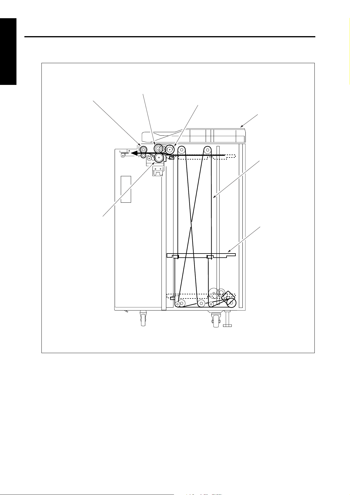
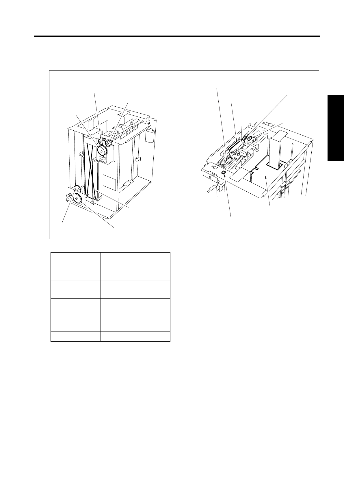
CENTER CROSS-SECTIONAL DRAWING
1 OUTLINE
Feed roller
Conveyance roller
Paper feed roller
Top cover
Up/down wire
(the other side
wire as well)
Double feed
prevention roller
Up/down plate
1-2
Page 11
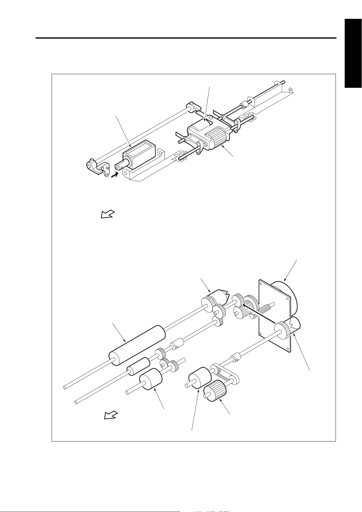
DRIVE SYSTEM DRAWING
C-403/C-404
[1] Paper feed drive section
LT First paper feed SD
(SD100)
FRONT
1 OUTLINE
Feed roller
Paper feed roller
Conveyance roller
FRONT
LT First paper feed MC
(MC 102)
Double feed
prevention roller
LT paper feed motor
(M101)
LT feed drive MC
(MC101)
Paper feed roller
Feed roller
1-3
Page 12
C-403/C-404
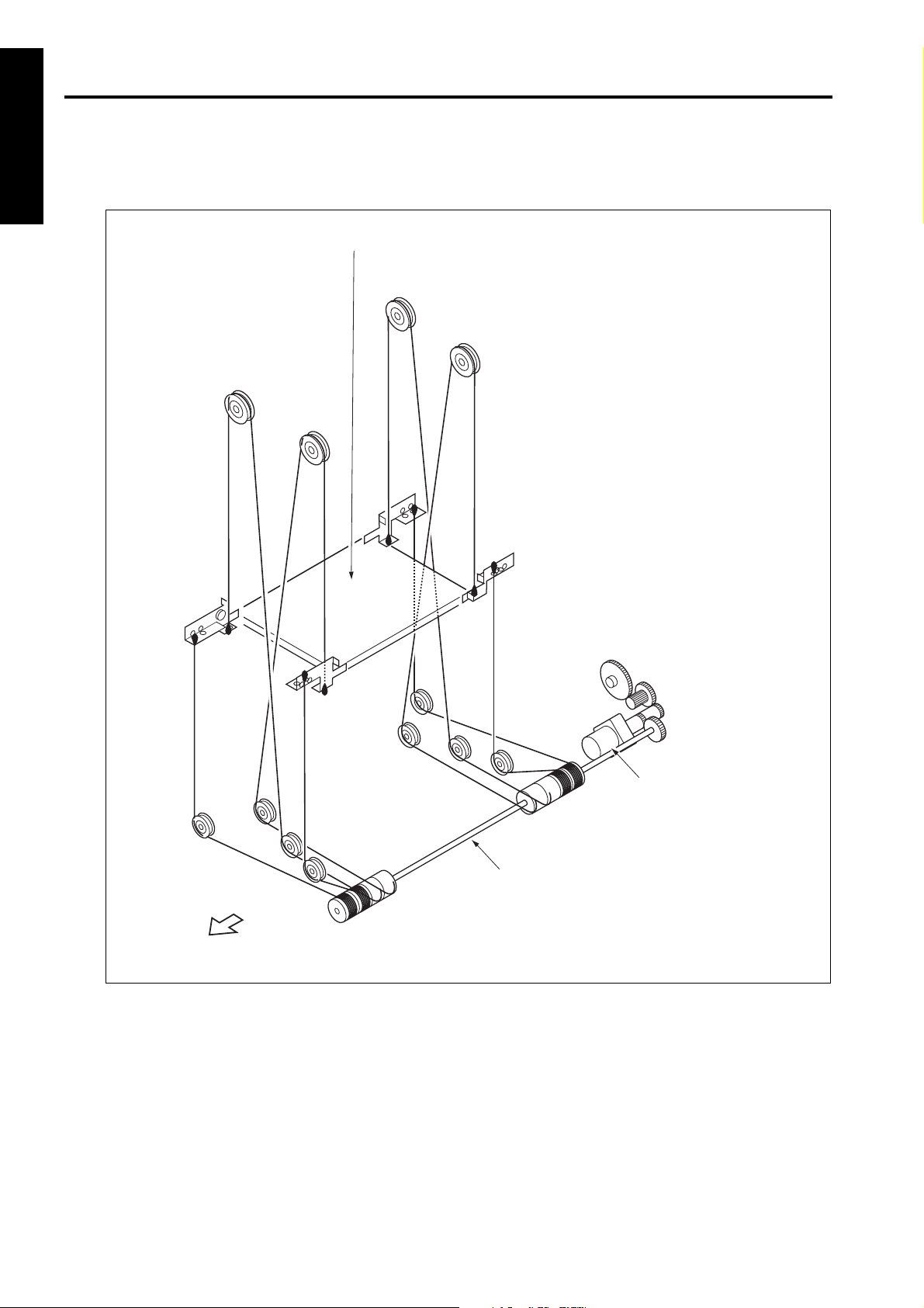
[2] Stacked paper up/down wire drive section
1 OUTLINE
a. C-403
Up/down plate
FRONT
LT up/down motor
(M100)
Up/down shaft
1-4
Page 13
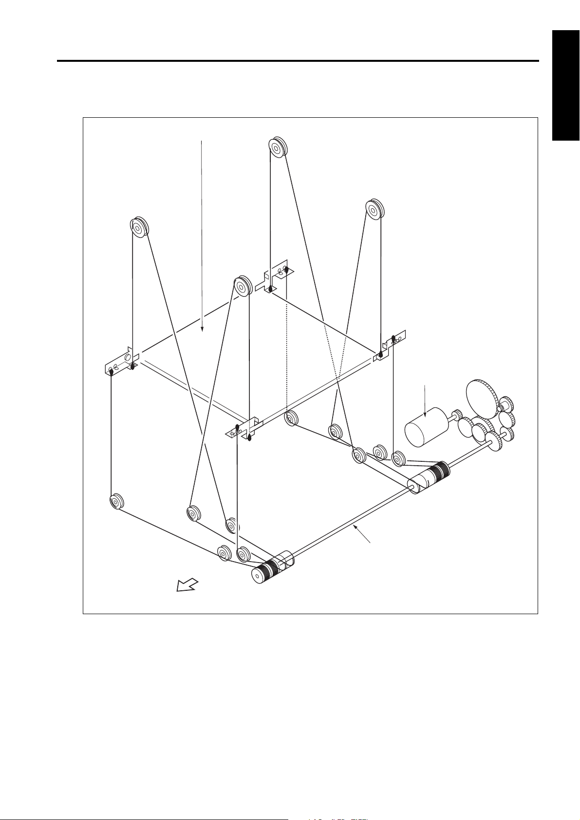
C-403/C-404
b. C-404
1 OUTLINE
Up/down plate
LT up/down motor
(M100)
FRONT
Up/down shaft
1-5
Page 14

1 OUTLINE
Blank page
Page 15

2
UNIT EXPLANATION
2 UNIT EXPLANATION
Page 16

2 UNIT EXPLANATION
Blank page
Page 17
PAPER FEED SECTION
[1] Composition
LT feed MC (MC101)
LT paper
feed motor
(M101)
LT first paper feed MC (MC102)
LT first paper feed SD
(SD100)
Paper dust
removing brush
Conveyance
roller
C-403/C-404
LT feed PS (PS106)
LT first paper
feed PS (PS107)
2 UNIT EXPLANATION
Up/down wire
(the other side wire as well)
LT up/down motor
(M100)
Remaining paper detection gear
[2] Mechanisms
Mechanism Method
Paper lifting *1 Wire drive
Paper feed Paper feed roller
No paper detection
Remaining paper
detection *2
Paper conveyance Roller conveyance
*1 Paper lifting
a.Up/down plate lifting drive operation
The up/down plate is lifted with the up/down
wires. When the top cover closes, LT up/down
motor (M100) rotates and the up/down plate connected to the up/down wires rises.
b.Up/down plate down drive operation
The up/down plate automatically lowers by 120
mm when the top cover is opened.
Subsequently, it is lowered by 120 mm each time
LT tray down drive switch (SW100) is pressed.
Photo sensor (PS108)
+actuator
Remaining paper detection gear+ photo sensor
(PS102, PS103, PS104,
PS105)
Up/down plate
LT tray down drive switch (SW 100)
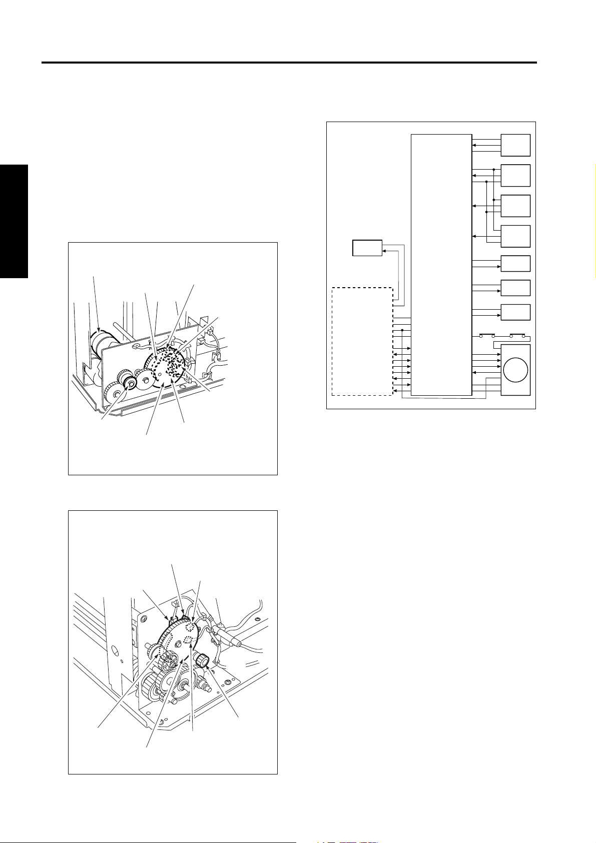
*2 Remaining paper detection
The LCT is equipped with a remaining paper
detection gear which rotates together with LT up/
down motor (M100) driving the up/down plate.
The remaining paper detection gear has an actuator to turn ON/OFF LT remaining paper detection PS1 (PS102), LT remaining paper detection
PS2 (PS103), LT remaining paper detection PS3
(PS104), and LT remaining paper detection PS4
(PS105).
2-1
Page 18
C-403/C-404
2 UNIT EXPLANATION
Each sensor is turned ON/OFF according to the
rotating position of the remaining paper detection gear and since this is linked with the up/down
position of the up/down plate, the remaining
paper quantity in the LCT can be determined by
monitoring the ON/OFF of each sensor. The
remaining paper quantity detected with the four
sensors is displayed on the main body display.
a. C-403
LT remaining paper
LT up/down motor (M100)
detection PS1
(PS102)
Actuator
LT remaining
paper detection
PS2 (PS103)
LT remaining
paper detection
PS3 (PS104)
Gear for M100
Remaining
LT remaining paper
detection PS4 (PS105)
paper detection
gear
b. C-404
LT remaining
paper detection
PS2 (PS103)
LT remaining paper
detection PS1 (PS102)
LT remaining paper
detection PS3 (PS104)
[3] First paper feed control
UPOP_PS
S_GND
CONV_PS
S_GND
PR_PS
SIDOP_PS
24V
CONT
24V
CONT
24V
CONT
24V
LCTM_CONT
LCTM_CLK
LCTM_F/R
LCTM_EM
GND
P_GND
5V
5V
MS101
5V
LT DB
HTR101
MAIN BODY
24V
PGND
5V
SGND
IO_DTXD
IO_UCLK
LCT_LATCH
IO_DCLK
ERR_OUT4
IO_URXD
ACK4
REQ4
The first paper is fed by the paper feed roller and
the feed roller driven by M101(LT paper feed) via
MC101(LT feed MC). The paper feed roller and
feed roller touche the paper when SD100 (LT first
feed) is ON, feeding the paper to the conveyance
roller. Then, SD100 (LT first paper feed) turns
OFF to release the paper feed roller and feed
roller from the paper. The conveyance roller is
also driven by M101, by turning ON MC102 (LT
first feed MC), paper is fed to the main body.
The related signals are: PS100 (LT top cover
open/close detection), PS106 (LT feed), PS107
(LT first feed), and PS110 (LT jam access door
open/close detection).
PS100
PS106
PS107
PS110
MC101
MC102
SD100
MS102
M101
Actuator
Remaining paper
detection gear
Gear for M100
LT remaining paper
detection PS4 (PS105)
2-2
Page 19

C-403/C-404
1. Operation
a. First paper feed timing
(1) Start of first paper feed
At predefined interval after the START button is
pressed.
(2) Start of second and subsequent papers
When PS106 (LT feed) is turned OFF by the preceding paper.
(3) OFF timing
When the main body M7 (paper exit) turns OFF.
b. Interlock
The power supply line of M101 (LT paper feed) is
equipped with MS101 (LT interlock/1) and
MS102 (LT interlock/2). When the top cover is
opened, MS101 turns OFF, and when the jam
access door is opened MS102 turns OFF,
thereby cutting off the power supply to M101.
Furthermore, the top cover is equipped with
PS100 (LT top cover open/close detection) and
the jam access door is equipped with PS110 (LT
jam access door open/close detection) and
when either of these doors is opened during
paper feed, the M101 drive signal is turned OFF
to stop the paper feed operation.
c. Internal heater
The LCT is equipped with HTR101 (LT internal
heater) to protect the paper from humidity.
HTR101 is directly controlled by the main body
PRCB (printer control board) rather than by the
LTDB (LT drive board).
2. Signals
a. Input signals
(1) UPOP_PS (PS100 to LTDB)
Top cover open/close detection signal
[L]: Cover opened
[H]: Cover closed
(2) CONV_PS (PS106 to LTDB)
Conveyance roller exit paper detection signal
[L]: Paper detected
[H]: Paper not detected
(3) PR_PS (PS107 to LTDB)
Conveyance roller entrance (pre-registration
position) paper detection signal
[L]: Paper detected
[H]: Paper not detected
(4) SIDOP_PS (PS110 to LTDB)
Jam access door open/close detection signal
[L]: Door opened
[H]: Door closed
(5) LCTM_EM (M101 to LTDB)
M101 rotation error detection signal
[L]: M101 rotating
[H]: M101 not rotating
(6) IO_DTXD (MAIN BODY to LTDB)
Serial data to transmit main body PRCB (printer
control board) operating status to LTDB
(7) LCT_LATCH (MAIN BODY to LTDB)
IO_DTXD signal latch signal
(8) IO_DCLK (MAIN BODY to LTDB)
IO_DTXD signal clock signal
(9) ERR_OUT4 (MAIN BODY to LTDB)
Signal to notify LTDB (LT drive board) when there
is error in the main body
(10) ACK4 (MAIN BODY to LTDB)
Serial data transmission enable signal from LCT
to main body PRCB (printer control board)
2 UNIT EXPLANATION
2-3
Page 20

C-403/C-404
2 UNIT EXPLANATION
b. Output signals
(1) CONT (LTDB to MC101)
MC101 (LT feed MC) ON/OFF drive signal
[L]: MC101 ON
[H]: MC101 OFF
(2) CONT (LTDB to MC102)
MC102 (LT first paper feed MC) ON/OFF drive
signal
[L]: MC102 ON
[H]: MC102 OFF
(3) CONT (LTDB to SD100)
SD100 ( LT first paper feed) ON/OFF drive signal
[L]: SD100 ON
[H]: SD100 OFF
(4) LCTM_CONT (LTDB to M101)
M101 (LT paper feed) ON/OFF control signal
[L]: M101 ON
[H]: M101 OFF
(5) IO_URXD (LTDB to MAIN BODY)
Serial data to transmit the LTDB (LT drive board)
operating status to main body PRCB
(6) IO_UCLK (LTDB to MAIN BODY)
IO_URXD signal clock signal
(7) REQ4 (LTDB to MAIN BODY)
Serial data send request signal from LCT to main
body PRCB
(8) LCTM_CLK (M101 to LTDB)
M101 (LT paper feed) rotational speed control
clock signal
(9) LCTM_F/R (M101 to LTDB)
M101 (LT paper feed) rotational direction indication signal
This machine always indicates [H]: normal rotation.
[4] Up/down plate drive control
LT DB
MAIN BODY
24V
PGND
SGND
IO_DTXD
IO_UCLK
LCT_LATCH
IO_DCLK
ERR_OUT4
IO_URXD
ACK4
REQ4
5V
When the top cover opens or closes, M100 (LT
up/down motor) rotates forward or backward to
move the up/down plate up or down. The up/
down plate descends by 120 mm each time
SW100 (LT tray down drive) is pressed while the
top cover is opened.
The related signals are PS100 (LT top cover
open/close detection), PS101 (LT lower limit
detection), and PS109 (LT upper limit detection).
1. Operation
a. Up/down plate descend timing
(1) ON timing
When the top cover is opened and PS100 (LT top
cover open/close detection) is turned OFF, M100
rotates backward to lower the up/down plate.
When SW100 (LT tray down drive) turns ON by
pressing, M100 rotates backward to move the
up/down plate down.
(2) OFF timing
M100 turns OFF at predefined interval after
PS100 turns OFF or SW100 turns ON. This in
turn lowers the up/down plate by 120 mm.
(3) Others
The up/down plate descends by 120 mm each
time SW100 is pressed until PS101 turns ON to
indicate the bottom limit of the up/down plate.
UPOP_PS
S_GND
SIG
S_GND
DW_SW
UP_PS
S_GND
5V
5V
5V
D1
D2
PS100
PS101
SW100
PS109
M100
2-4
Page 21

C-403/C-404
b. Up/down plate ascend timing
(1) ON timing
When the top cover is closed and PS100 (LT top
cover open/close detection) is turned ON, M100
(LT UP/DOWN) rotates forward to raise the up/
down plate.
(2) OFF timing
When the up/down plate rises and PS109 (LT
upper limit detection) turns ON to indicate the
detection of the topmost paper, M100 (LT UP/
DOWN) turns OFF and stops the up/down plate.
The up/down plate also stops when the top cover
is opened and PS100 (LT top cover open/ close
detection) turns OFF.
2. Signals
a. Input signals
(1) SIG (PS101 to LTDB)
Up/down plate lower limit detection signal
[L]: Up/down plate not at lower limit
[H]: Up/down plate at lower limit
(2) UP_PS (PS109 to LTDB)
Up/down plate upper limit detection signal
[L]: Up/down plate not at upper limit
[H]: Up/down plate at upper limit
(3) DW_SW (SW100 to LTDB)
SW100 (LT tray down switch) ON/OFF detection
signal
[L]: SW100 ON
[H]: SW100 OFF
b. Output signal
(1) D1, 2 (LTDB to M100)
M100 (LT UP/DOWN) drive signal
These signals switches the direction of the drive
current to control the rotation direction of M100.
[5] Remaining paper detection/No paper
detection control
LT DB
MAIN BODY
24V
PGND
SGND
IO_DTXD
IO_UCLK
LCT_LATCH
IO_DCLK
ERR_OUT4
IO_URXD
ACK4
REQ4
5V
The remaining paper quantity is detected by
PS102 (LT remaining paper detection 1), PS103
(LT remaining paper detection 2), PS104 (LT
remaining paper detection 3), and PS105 (LT
remaining paper detection 4) and no paper
detection is made by PS108 (LT no paper detection).
The signals detected by these sensors are controlled by LTDB (LT drive board) and displayed on
the main body display.
1. Operation
a. Remaining paper detection control
The remaining paper quantity is determined from
the ON/OFF combination of sensors PS102 (LT
remaining paper detection 1), PS103 (LT remaining paper detection 2), PS104 (LT remaining
paper detection 3), and PS105 (LT remaining
paper detection 4) which detect the rotational
position of M100 (LT UP/DOWN) that is driving
the up/down plate. Each sensor turns ON or
OFF according to the position of the remaining
paper detection gear which is linked with the
rotation of M100.
The remaining paper quantity is detectable at
eight levels, but it is displayed on the main body
display as five levels.
SIG
S_GND
SIG
S_GND
SIG
S_GND
SIG
S_GND
0_PS
S_GND
5V
5V
5V
5V
5V
D1
D2
PS102
PS103
PS104
PS105
PS108
M100
2 UNIT EXPLANATION
2-5
Page 22

C-403/C-404
<Remaining paper quantity and display>
Stacked
paper
quantity
0 to 700 OFF OFF OFF OFF 1 flashing
701 to 1200 ON OFF OFF OFF 1 on
1201 to 1700 ON ON OFF OFF 2 on
1701 to 2200 ON ON ON OFF 2 on
2201 to 2700 ON ON ON ON 3 on
2701 to 3200 OFF ON ON ON 3 on
3201 to 3700 OFF OFF ON ON 4 on
2 UNIT EXPLANATION
3701 or more OFF OFF OFF ON 4 on
Caution:The remaining paper quantity is indicated on
b. No paper detection control
When there is no more paper inside the LCT,
PS108 (LT no paper detection) turns ON and a
message is displayed on the main body display.
PS102 PS103 PS104 PS105
the control panel with four horizontal bars.
Stacked paper quantity differs depending on
the thickness of the paper.
Remaining
paper quantity
display
2. Signals
a. Input signals
(1) SIG (PS102 to LTDB)
Remaining paper detection gear rotational position detection signal
[L]: PS102 OFF
[H]: PS102 ON
(2) SIG (PS103 to LTDB)
Remaining paper detection gear rotational position detection signal
[L]: PS103 OFF
[H]: PS103 ON
(3) SIG (PS104 to LTDB)
Remaining paper detection gear rotational position detection signal
[L]: PS104 OFF
[H]: PS104 ON
(4) SIG (PS105 to LTDB)
Remaining paper detection gear rotational position detection signal
[L]: PS105 OFF
[H]: PS105 ON
(5) 0_PS (PS108 to LTDB)
LCT no paper detection signal
[L]: No paper
[H]: Paper present
2-6
Page 23

3
DISASSEMBLY/ASSEMBLY
3 DIS./ASSEMBLY
Page 24

This section explains how to disassemble and reassemble the machine.
When disassembling and reassembling the machine, follow the precautions given below.
1. Be sure the power cord has been unplugged from the wall outlet.
3 DIS./ASSEMBLY
2. The disassembled parts must be reassembled following the disassembly procedure in reverse unless otherwise specified.
3. Care should be taken not to lose small parts. Care should also be
taken not to install small parts in wrong places.
4. Do not operate the machine before installing all the disassembled
parts completely.
5. Removal of some screws is prohibited in this section. Never loosen
them.
Page 25
PAPER FEED SECTION
C-403/C-404
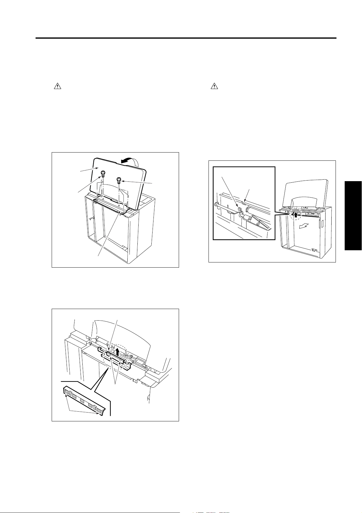
[1] Cleaning the Paper Dust Removing
Brush
Caution:If LT is connected to the main
body, make sure that main body
power plug is disconnected
from the power outlet.
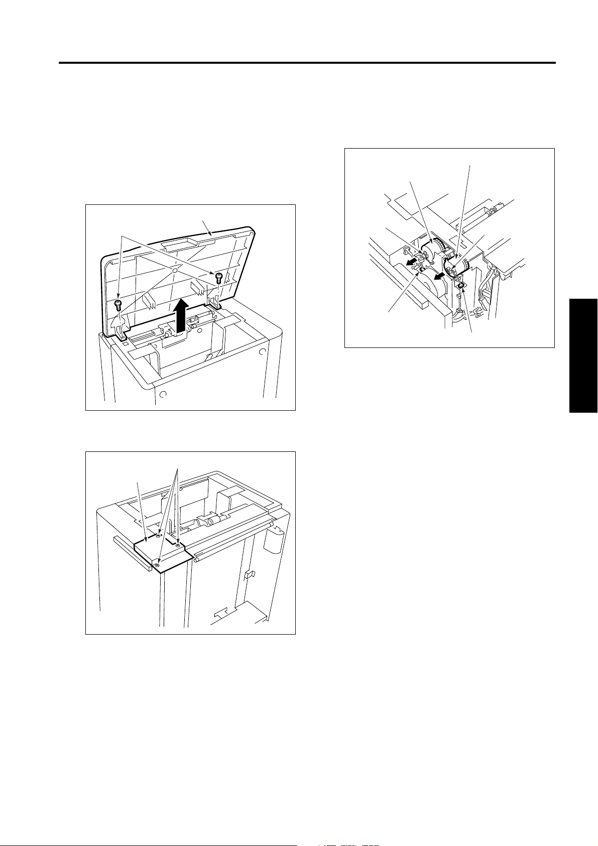
a. Procedure
(1) Open the top cover.
(2) Remove six screws to detach the paper feed
cover B.
To p
cover
Screws
Screws
[2] Cleaning the LT feed PS (PS106)/LT
first paper feed PS (PS107)
Caution:If LT is connected to the main
body, make sure that main body
power plug is disconnected
from the power outlet.
a. Procedure
(1) Looking into the paper exit side of the LCT from
below, and clean sensors through the cavity for
LT feed PS (PS106) and the cavity for LT first
paper feed (PS107) using a blower brush.
Cavity for PS106
Cavity for PS107
Paper
exit
side
3 DIS./ASSEMBLY
Paper feed cover B
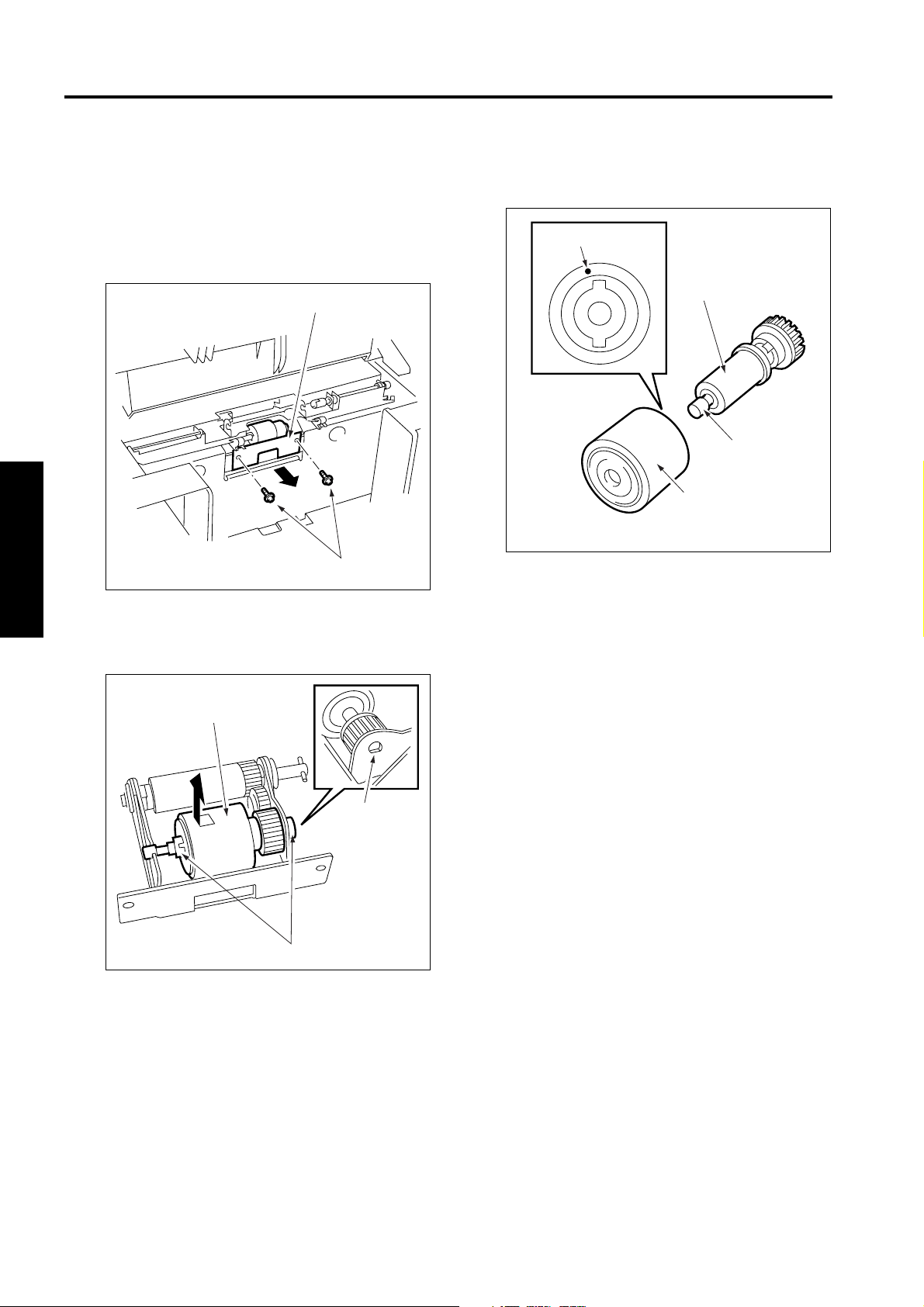
(3) Insert a flat bladed screwdriver in the cavities (in
two locations) for paper dust removing brush to
release the locking lugs, then remove the paper
dust removing brush.
Paper dust removing brush
Cavity
Locking lugs
(4) Clean the paper dust removing brush using a
blower brush.
(5) Reinstall the above parts following the removal
steps in reverse.
3-1
Page 26
C-403/C-404
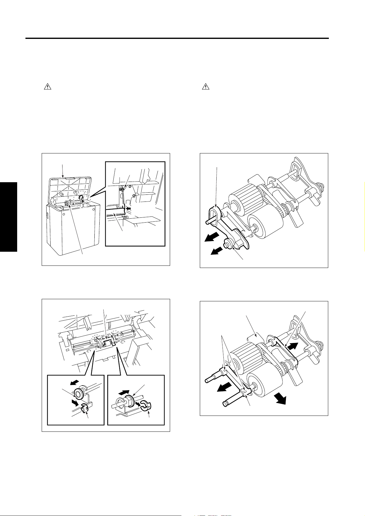
[3] Removing and Reinstalling the Paper
Feed Roller Unit
Caution:If LT is connected to the main
body, make sure that main body
power plug is disconnected
from the power outlet.
a. Procedure
(1) Open the top cover.
(2) Remove the spring from the paper feed roller
unit.
Top cover
Spring
Remove
this.
Paper feed roller unit
3 DIS./ASSEMBLY
[4] Replacing the Paper Feed Roller Rub-
ber/Feed Roller Rubber
Caution:If LT is connected to the main
body, make sure that main body
power plug is disconnected
from the power outlet.
a. Procedure
(1) Remove the paper feed roller unit.
(2) Remove the bearing and paper feed reference
actuator.
Paper feed reference actuator
Paper feed roller unit
(3) After removing two stop rings, remove the two
bearings outward to remove the paper feed roller
unit.
Paper feed roller unit
Bearing
Stop ring
Bearing
Stop ring
Bearing
(3) Remove two stop rings.
(4) Remove two bearings outward to detach the
roller section from the roller fitting.
Roller fitting
Stop rings
Bearing
Bearing
(4) Reinstall the above parts following the removal
steps in reverse.
3-2
Page 27
C-403/C-404
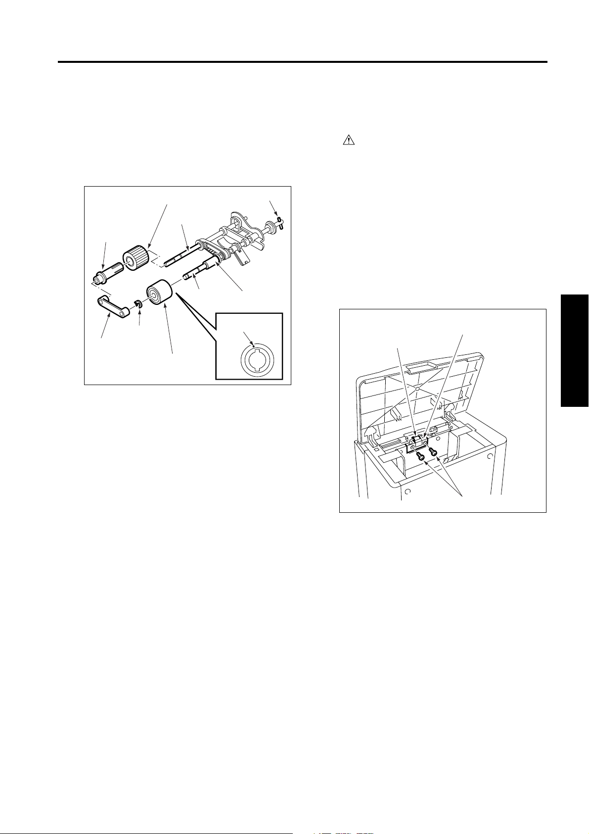
(5) Remove the bearing from the opposite side of the
coupling, then remove the paper feed roller from
the shaft.
(6) Remove the stop ring to pull the feed roller from
the shaft.
(7) Remove the rubber from each roller.
Coupling
Feed roller
Paint mark
Paper feed
roller
Bearing
Paper feed roller rubber
Shaft
Shaft
Stop ring
Feed roller rubber
(8) Reinstall the above parts following the removal
steps in reverse.
Caution1: Make sure rollers and rubber por-
tions are oriented properly when
reinstalling them.
Caution2: Make sure the one-way clutch direc-
tion is correct.
Caution3: Check whether grease or the like is
present on each roller.
[5] Replacing the Double Feed Preven-
tion Roller Rubber
Caution:If LT is connected to the main
body, make sure that main body
power plug is disconnected
from the power outlet.
a. Procedure
Caution: With the power held on, press the LT
tray down switch (SW100) to move the
up/down plate down to the bottom in
advance.
(1) Remove the paper feed roller unit.
(2) Remove two screws to detach the double feed
prevention roller unit cover.
Double feed
Double feed
prevention roller
prevention roller unit cover
Screws
3 DIS./ASSEMBLY
3-3
Page 28
C-403/C-404
(3) Remove two screws to detach the double feed
prevention roller unit.
(5) Remove the double feed prevention roller rubber
from the double feed prevention roller.
Caution: When reinstalling the double feed pre-
vention roller unit, tighten the screws
on the rear side first.
Double feed prevention roller unit
Screws
(6) Reinstall the double feed prevention roller in the
Paint mark
Double feed
prevention roller
Shaft
Double feed
prevention roller
rubber
reverse order of the removal procedure.
3 DIS./ASSEMBLY
(4) Remove two stop rings, fit the shaft into the D-cut
in the fitting, and remove the double feed prevention roller together with the shaft.
Caution1: Make sure the double feed preven-
tion roller rubber is oriented properly
when reinstalling it.
Caution2: Check whether scratch or the like is
Double feed prevention roller
visible on the pet cover for the drive
gear.
Caution3: Check whether grease or the like is
present on double feed prevention
roller.
D-cut
Stop ring
3-4
Page 29
C-403/C-404
[6] Replacing the LT feed MC (MC101)/LT
first paper feed MC (MC102)
a. Procedure
(1) Open the top cover.
(2) Remove the spring from the paper feed roller
unit.
(3) Remove two screws to detach the top cover.
Top cover
Screws
(4) Remove three screws to detach the clutch
replacement cover.
(5) Disconnect two relay connectors (CN765,
CN766) of the clutches.
(6) Remove the stop ring to detach each clutch.
LT first paper feed MC (MC102)
LT feed MC (MC101)
Stop ring
Stop ring
Relay connector
(CN766)
Relay connector (CN765)
(7) Reinstall the above parts following the removal
steps in reverse.
Caution: When installing each MC, make sure
that the stopper of each clutch is on
the predefined position.
3 DIS./ASSEMBLY
Clutch
replacement cover
Screws
3-5
Page 30

C-403/C-404
[7] Replacing the C-403 Up/Down Wires
Caution: With the power held on, press the LT
tray down switch (SW100) to move the
up/down plate down to the bottom in
advance.
a. Procedure
(1) Open the top cover.
(2) Remove the clutch replacement cover.
(3) Remove five screws to detach the right side
cover.
3 DIS./ASSEMBLY
Right side
cover
Screws
Screws
(5) Remove twelve screws to detach the rear cover.
Screw
Screws
Screws
Screws
Rear cover
(6) Remove the five relay connectors (CN749,
CN780, CN781, CN782, CN783) to disconnect
the wiring harness from the up/down motor
mounting assembly.
(7) Remove the E-ring to detach the up/down gear.
(8) Pull the pin from the shaft.
(9) Remove the E-ring to detach the bearing.
(10) Remove three screws to detach the up/down
motor assembly.
(4) After opening the jam access door, remove six
screws to detach the front cover.
Caution: When removing the front cover, close
the jam access door after removing
the screws.
Jam access door
Screws
Right side cover
Screws
Relay connector
Up/down
motor mounting
assembly
Shaft
(CN749)
Screw
Pin
Screw
Bearing
E-ring
Relay
connector
(CN780)
Relay
connector
(CN781)
Relay
connector
(CN782)
Relay
connector
(CN783)
Screw
Up/down
gear
E-ring
3-6
Page 31

(11) Replace the up/down wire following the instruc-
tions in “Removing Up/Down Wires’’ and “Installing Up/Down Wires.’’
Caution: Two sets of four up/down wires with
different length, one set at the front
and the other at the back, are used.
Wires with the same length can be
used either at the front or back if they
are used in the same location.
1323.6mm
Wire A
1250.3mm
Wire B
C-403/C-404
Wire C
Wire D
769.3mm
661mm
3 DIS./ASSEMBLY
3-7
Page 32

C-403/C-404
<Removing the Up/Down Wires>
Wire A
Wire B
Wire B
Wire A
Up/down plate
2. Release the metal
ball to remove wire
C.
18. Release the metal
ball to remove wire
A.
4. Release the metal
ball to remove wire
D.
14. Release the metal
ball to remove wire
A.
7. Release the metal
ball to remove wire
C.
9. Release the metal
ball to remove wire
3 DIS./ASSEMBLY
D.
12. Release the metal
ball to remove wire
B.
Wire C
Wire D
6. Remove the E-ring.
8. Remove the pulley.
10. Remove the pulley.
FRONT
Up/down
shaft
Wire D
Wire C
16. Release the metal
ball to remove wire
B.
1. Remove the E-ring.
3. Remove the pulley.
5. Remove the pulley.
15. Remove the Ering, then remove
the pulley to
release wire B.
11. Remove the E-ring,
then remove the
pulley to release
wire B.
13. Remove the pulley to
release wire A.
3-8
17. Remove the pulley
to release wire A.
Page 33

<Installing the Up/Down Wires>
C-403/C-404
Wire A
Wire B
7. Insert wire A in the
pulleys, then attach a
metal ball.
15. Insert wire C in the
pulleys, then attach a
metal ball.
12. Insert wire D in the
pulleys, then attach a
metal ball.
10. Insert wire B in the
pulleys, then attach a
metal ball.
Wire C
Wire D
13. Insert wire C in the up/
down shaft, attach a
pulley, and secure the
pulley with an E-ring.
14. Wind wire C around
the pulley by 6 turns in
such a manner that the
wire can be pulled
from over the pulley.
Wire B
Wire A
FRONT
Up/down plate
1. Insert wire A in
6. the up/down
shaft, attach
pulleys, then
pull the wire
from under the
pulleys.
Up/down
shaft
20. Insert wire B in the pulleys,
then attach a metal ball.
2. Insert wire A in the pulleys,
then attach a metal ball.
17. Insert wire D in the pulleys,
then attach a metal ball.
5. Insert wire B in the pulleys,
then attach a metal ball.
Wire D
Wire C
3 DIS./ASSEMBLY
18. Insert wire C in the up/
down shaft, attach a
pulley, and secure the
pulley with an E-ring.
19. Wind wire C around
the pulley by 6 turns
in such a manner that
the wire can be pulled
from over the pulley.
6 turns
6 turns
11. Insert wire D in the up/
down shaft, attach a
pulley, and wind wire
D around the pulley by
six turns in such a
manner that the wire
can be pulled from
over the pulley.
6 turns
3. Insert wire B in the up/
8. down shaft, attach a
pulley, and secure the
pulley with E-rings.
4. Pull wire B from under the
9. pulleys.
3-9
16. Insert wire D in the up/
down shaft, attach a
pulley, and wind wire
D around the pulley by
six turns in such a
manner that the wire
can be pulled from
over the pulley.
6 turns
Page 34

C-403/C-404
(12) After installing the up/down wires, make sure the
up/down wires are passed in the grooves in the
[8] Replacing the C-404 Up/Down Wires
a. Procedure
pulleys properly and wires do not run on the
sides of the pulleys. Also make sure the up/down
plate can be moved up and down smoothly by
hand.
Caution: With the power held on, press the LT
tray down switch (SW100) to move the
up/down plate down to the bottom in
advance.
Caution: If the up/down plate does not move up
and down smoothly, reinstall the up/
down wires.
(13) Install the up/down wire drive motor assembly,
up/down gear, and relay connectors, following
the removal steps in reverse.
(14) Remove the E-ring to detach the idle gear.
(1) Remove the clutch replacement cover, side
cover (right), front cover, and rear cover following
the steps (1) to (5) in [7] Replacing the C-403 Up/
Down Wires.
(2) Remove the E-ring.
(3) Remove the five screws to detach the gear cover.
(4) Remove the two bearings.
(15) Rotate the remaining paper detection gear until
the round hole in this gear is aligned with the
Screw
oblong hole in the up/down motor mounting
assembly.
Caution: Align when the up/down plate is in low-
est position.
3 DIS./ASSEMBLY
Up/down motor
mounting assembly
Remaining paper
detection gear
E-ring
Screw
Gear cover
Bearing
Screws
Bearing
Round
hole
Idle gear
E-ring
Oblong
hole
(16) Install the idle gear.
(17) Attach the covers following the removal steps in
reverse.
Caution1: After replacing the up/down wires,
make horizontal and centering
adjustment of the up/down plate.
(Refer to “ADJUSTMENT SECTION.”)
(5) Remove the gear A.
(6) Remove the E-ring to remove gear B.
(7) Remove the detent pin for gear B from the up/
down pulley shaft.
(8) Remove the E-ring and bearing to remove gear
C.
Gear A
Pin
Gear B
Bearing
Up/down pulley shaft
Gear C
E-ring
E-ring
3-10
Page 35

C-403/C-404
(9) Remove the bearing behind gear C.
(10) Remove the E-ring to remove the up/down gear.
(11) Remove the detent pin for up/down gear from the
up/down pulley shaft.
(12) Remove the E-ring to remove gear D.
(13) Remove the E-ring to remove the remaining
paper detection gear.
(14) Remove four relay connectors (CN780, CN781,
CN782, and CN783) to disconnect the wiring
harness from the up/down motor mounting
assembly.
Relay connector
(CN780)
Remaining paper
detection gear
Gear D
E-ring
Relay
connector
(CN781)
Relay connector
(CN782)
Up/down
motor mounting
assembly
(17) Replace the up/down wires following the instruc-
tions in “Removing the Up/Down Wires” and
“Installing Up/Down Wires.”
Caution: Two sets of four up/down wires with
different length, one set at the front
and the other at the back, are used.
Wires with the same length can be
used either at the front or back if they
are used in the same location.
1057.3mm
Wire A
692.1mm
Wire B
1321.7mm
Wire C
1303.1mm
Wire D
3 DIS./ASSEMBLY
Pin
Up/down
gear
E-ring
Up/down pulley shaft
Bearing
Relay
connector
(CN783)
E-ring
(15) Remove the E-ring to remove the bearing.
(16) Remove the six screws to remove the up/down
motor mounting assembly.
Up/down motor mounting assembly
Screws
Bearing
E-ring
Screws
3-11
Page 36

C-403/C-404
<Removing the Up/Down Wires>
Up/down plate
Wire C
Wire D
Wire C
Wire D
14. Release the metal
ball to remove wire
D.
7. Release the metal
ball to remove wire
A.
9. Release the metal
ball to remove wire
3 DIS./ASSEMBLY
B.
12. Release the metal
ball to remove wire
C.
Wire B
2. Release the metal
ball to remove wire
A.
18. Release the metal
ball to remove wire
D.
4. Release the metal
ball to remove wire
B.
16. Release the metal
ball to remove wire
C.
Wire A
1. Remove the E-ring.
3. Remove the pulley.
Wire A
6. Remove the E-ring.
8. Remove the pulley.
10. Remove the pulley.
Wire B
FRONT
11. Remove the E-ring,
then remove the
pulley to release
wire C.
Up/down shaft
13. Remove the pulley to
release wire D.
5. Remove the pulley.
15. Remove the E-ring,
then remove the
pulley to release
wire C.
17. Remove the pulley
to release wire D.
3-12
Page 37

<Installing the Up/Down Wires>
C-403/C-404
Wire C
Wire D
Wire C
Wire D
7. Insert wire D in the
pulleys, then attach a
metal ball.
15. Insert wire A in the
pulleys, then attach a
metal ball.
12. Insert wire B in the
pulleys, then attach a
metal ball.
10. Insert wire C in the
pulleys, then attach a
metal ball.
Wire A
Wire B
13. Insert wire A in the up/down
shaft, attach a pulley, and
secure the pulley with an E-ring.
14. Wind wire A around the pulley
by 6 turns in such a manner
that the wire can be pulled
from over the pulley.
6 turns
11. Insert wire B in the up/down shaft,
attach a pulley, and wind wire B
around the pulley by six turns in
such a manner that the wire can
be pulled from over the pulley.
Up/down plate
FRONT
3. Insert wire C in the up/down
8. shaft, attach a pulley, and
4. Pull wire C from under the
9. pulleys.
Up/down
shaft
1. Insert wire D in the
6. up/down shaft, attach
pulleys, then pull wire
D from under the
pulleys.
secure the pulley with E-rings.
20. Insert wire A in the
pulleys, then attach a
metal ball.
2. Insert wire D in the
pulleys, then attach a
metal ball.
17. Insert wire B in the
pulleys, then attach a
metal ball.
5. Insert wire C in the
pulleys, then attach a
metal ball.
Wire B
Wire A
18. Insert wire A in the up/
down shaft, attach a
pulley, and secure the
pulley with an E-ring.
19. Wind wire A around the
pulley by 6 turns in such
a manner that the wire
can be pulled from over
the pulley.
16. Insert wire B in the up/
down shaft, attach a
pulley, and wind wire B
around the pulley by six
turns in such a manner
that the wire can be
pulled from over the
pulley.
3 DIS./ASSEMBLY
6 turns
6 turns
6 turns
3-13
Page 38

C-403/C-404
(18) After installing the up/down wires, check whether
they are engaged with the pulleys properly and
whether they do not ride over the pulleys. Next,
move the up/down plate manually to check
whether it moves up and down smoothly.
Caution: If the up/down plate does not move
smoothly, remove the up/down wires
and install them again.
(19) Install the up/down motor mounting assembly,
relay connectors, remaining paper detection
gear, gear D, and up/down gear following the
removal steps in reverse.
(20) Rotate the remaining paper detection gear until
the round hole in this gear is aligned with the
oblong hole in the up/down motor mounting
assembly.
Up/down motor
mounting assembly
Remaining paper
detection gear
3 DIS./ASSEMBLY
Oblong hole
Round hole
Caution: Align them when the up/down plate is
at the bottom.
(21) Install gear C.
(22) Attach the other gears, gear cover, and external
covers following the removal steps in reverse.
Caution: After replacing the up/down wires,
make horizontal and centering adjust-
ment of the up/down plate. (Refer to
“ADJUSTMENT SECTION.”)
3-14
Page 39

SERVICE MANUAL
Cover Inserter B
Cover Inserter E
2004.01
Ver. 1.0
Page 40

Page 41

CONTENTS
CONTENTS
SAFETY AND IMPORTANT WARNING ITEMS
Refer to the Di551/Di650/Di5510/Di7210
service manual on page ........................................ S-1
1. OUTLINE
COVER INSERTER B/E PRODUCT
SPECIFICATIONS.....................................................1-1
CENTER CROSS SECTION .....................................1-2
DRIVE SYSTEM DIAGRAM ......................................1-3
FEEDING PROCESS ................................................1-4
[1] Automatic Sheet Feeding
(online operation) ......................................1-4
[2] Manual Sheet Feeding (offline operation) ..1-4
2. UNIT EXPLANATION
EXTERNAL SECTION...............................................2-1
[1] Composition ...............................................2-1
[2] Mechanisms ...............................................2-1
[3] Interlock control ..........................................2-1
PAPER FEED UNIT...................................................2-2
[1] Composition ...............................................2-2
[2] Mechanisms ...............................................2-2
[3] Feed Control...............................................2-3
3. DISASSEMBLY/ASSEMBLY
EXTERNAL SECTION...............................................3-1
[1] Detaching / Re-installing
the External covers.....................................3-1
PAPER FEED UNIT...................................................3-2
[1] Replacing the Paper feed roller and
Feed roller ..................................................3-2
[2] Replacing the Double feed prevention roller
and Torque limiter ......................................3-3
2 UNIT EXPLANATION 1 OUTLINE3 DIS./ASSEMBLY
Page 42

1 OUTLINE2 UNIT EXPLANATION3 DIS./ASSEMBLY
Blank page
Page 43

1
OUTLINE
1 OUTLINE
Page 44

1 OUTLINE
Blank page
Page 45

Cover Inserter B/Cover Inserter E
COVER INSERTER B/E PRODUCT SPECIFICATIONS
[1] Type
Type:
Sheet feeder employing torque-limiter separation
[2] Functions
Automatic sheet feed (online operation):
The Cover Inserter B/E automatically feeds
sheets into the finisher in accordance with
instructions from the main body.
Manual sheet feed (offline operation):
User feeds sheets into finisher by operating the
PI operation panel.
User can select from the following four finishing
modes:
• Single-staple mode (staple at rear)
• Two-staple mode (flat stapling)
• Punch mode (with PK)
• Stitch-and-fold mode (available only if
mounted to the FN-6/10)
• Three-fold mode (available only if mounted
to the FN-6/10)
* Manual sheet feed is only available with the
lower tray.
This is not allowed for wide papers.
[3] Copy Paper
Plain paper:
60 to 90 g/m
paper, recycled paper
Special paper:
• 50 to 59 g/m
paper, recycled paper
• 91 to 200 g/m
paper, recycled paper
Printing paper:
• Double-sided art paper
• Mat coating paper
• High-quality paper
Upper tray copy sizes:
• Metric area
A4, A4R, B5, B5R, A5
• Inch area
8.5
11, 8.5×11R, 5.5×8.5
×
Lower tray copy sizes:
• Metric area
A3, B4, A4, A4R, B5, B5R, A5, F4
wide paper (314mm x 445mm max.)
• Inch area
17, 8.5×14, 8.5×11, 8.5×11R, 5.5×8.5,
11
×
wide paper (314mm x 445mm max.)
2
or 17lbs to 24lbs high-quality
2
or 13lbs to 16lbs high-quality
2
or 24lbs to 45lbs high-quality
Paper staking capacity:
Up to 200 sheets (when using 128 g/m
28lbs-equivalent paper) to max. height of
30mm
Paper curling:
Max. 10 mm
5 sheets
Amount of curl
2
or
[4] Power, Weight, Dimensions
Power source:
24VDC, 5VDC (supplied from FNS)
Maximum power:
30VA
Weight:
Approx. 10.5 kg
External dimensions:
Approx. 511(W)
620(D)×220(H) (mm)
×
[5] Maintenance
Maintenance:
Same as for the main body.
Service life:
Same as the main body.
[6] Operating environment
C (50°F to 86°F)
Temperature: 10 to 30
Humidity: 10 to 80% RH
Note: The information herein may be subject to
change for improvement without notice.
°
1 OUTLINE
1-1
Page 46

Cover Inserter B/Cover Inserter E
CENTER CROSS SECTION
1 OUTLINE
Up/down plate/U
Side guide plate
Paper feed roller
Feed roller
Up/down plate/L
Tray up/down motor/L (M202)
Paper feed roller
Double feed prevention roller
Tray up/down motor/U
(M201)
Conveyance roller /U
Feed roller
Conveyance roller /L
Double feed prevention roller
1-2
Page 47

DRIVE SYSTEM DIAGRAM
Feed roller
Sheet feed SD/U (SD201)
Conveyance MC/U (MC201)
Double feed prevention roller
Conveyance MC/L
(MC202)
Conveyance roller /U
Registration MC
(MC203)
Feed roller
Conveyance roller /L
Double feed prevention roller
Paper feed roller Paper feed roller
PI conveyance motor (M203)
Sheet feed SD/L (SD202)
Cover Inserter B/Cover Inserter E
1 OUTLINE
Feed roller
Paper feed roller
Tray up/down motor/U (M201)
Sheet feed SD/U/L
(SD201/SD202)
FRONT
FRONT
1-3
Tray up/down motor/L (M202)
Page 48

Cover Inserter B/Cover Inserter E
FEEDING PROCESS
[1] Automatic Sheet Feeding (online
1 OUTLINE
operation)
Tray up/down motors/U/L (M201/M202) raise the
Up/down plate/U/L.
When sheet feed SD/U/L (SD201/SD202) and
conveyance MC/U/L (MC201/MC202) come ON,
the drive of PI conveyance motor (M203) is transmitted and the sheets are fed, one by one, by
paper feed, feed, and double feed prevention rollers.
For the fed sheet, a loop is formed at the conveyance rollers /U/L to correct the bend temporarily,
and then the sheet is conveyed.
Sheets are stacked in the FNS as cover sheets
for papers conveyed from the main body, and
then applied with finishing processes.
Feed roller
Tray up/down motor (M201)
Paper feed roller
Up/down plate/U
Conveyance
roller /U
[2] Manual Sheet Feeding (offline opera-
tion)
M201/M202 (tray up/down/U/L) raises the Up/
down plate/L.
When sheet feed SD/U/L (SD201/SD202) and
conveyance MC/U/L (MC201/MC202) come ON,
the drive of PI conveyance motor (M203) is transmitted and all sheets set on the lower tray are fed
into the FNS stacker by paper feed, feed, and
double feed prevention rollers. FNS carries out
finishing processes.
In this case, a loop is formed at the conveyance
roller /L for the sheet and the bend is corrected
temporarily, and then the sheet is conveyed.
Paper feed roller
Up/down plate/L
Feed roller
Tray up/down
motor/L (M202)
Up/down plate/L
Tray up/down motor/L (M202)
Double feed prevention roller
Conveyance roller /L
Double feed prevention roller
Conveyance roller /L
1-4
Page 49

2
UNIT EXPLANATION
2 UNIT EXPLANATION
Page 50

2 UNIT EXPLANATION
Blank page
Page 51

EXTERNAL SECTION
[1] Composition
Connecting cover
Lower cover
Cover Inserter B/Cover Inserter E
Top cover
Release lever
2 UNIT EXPLANATION
Lower tray
[2] Mechanisms
Mechanism Method
Clearing paper jams*1 Release lever
*1 Clearing paper jams
Clear paper jams with the following procedure:
(1) Lift the release lever.
(2) In that status, lift up the upper tray in a slanting
direction.
Top cover
Release lever
(3) Remove paper jams.
Upper tray
Operation panel cover
[3] Interlock control
24V
24V
Interlock control uses MS201 (PI interlock MS)
that detects the opened upper tray.
1. Operation
a. Detecting the opened upper tray
MS201 (PI interlock) is a switch for the interlock.
When opening the upper tray of PI, MS201 goes
OFF and 24V power from FNS CB is shut off.
2. Signals
a. Input signals
(1) 24V, 24V (FNS CB to PIDB)
Input from a DC24V power source
MS201
24V
24V
PIDBFNS CB
2-1
Page 52

Cover Inserter B/Cover Inserter E
PAPER FEED UNIT
[1] Composition
Conveyance MC/U (MC201)
Double feed prevention roller
Tray up/down motor/U
(M201)
Conveyance roller /U
Conveyance MC/L
2 UNIT EXPLANATION
(MC202)
Registration MC
(MC203)
Feed roller
Sheet feed SD/U (SD201)
Paper feed roller
Width regulation plate
Up/down plate/U
Width regulation plate
Feed roller
Conveyance roller /L
Double feed prevention roller
Paper feed roller
[2] Mechanisms
Mechanism Method
Pickup section Upward feeding method,
Oscillated feed roller,
Paper feed roller
Sheet feed section Reverse torque limiter
method,
Double feed prevention
roller.
Torque limiter
PI conveyance motor
(M203)
Sheet feed SD/L (SD202)
Feed roller
Up/down plate/L
Tray up/down motor/L (M202)
Sheet feed SD/U/L
(SD201/SD202)
FRONT
Loop formation Thrust method
Conveyance rollers /U/L
2-2
Page 53

[3] Feed Control
Cover Inserter B/Cover Inserter E
24V
24V
MPI_DRV_SEL
MPI_M_CONT
MPI_M_F/R
MPI_SD_CONT
MPI_MC_CONT
M203 P/S
M203 CLK
M203 LD
M203 F/R
MPI_S_IN1_1
MPI_S_IN2_1
MPI_S_IN2_2
MPI_S_OUT1_1
MPI_S_OUT1_2
MPI_S_OUT2_1
MPI_S_OUT2_2
PS201 IN
PS206 IN
VR201 IN
VR202 IN
FNS CB
MS2
PG
PG
5V
5V
SG
SG
MC203
24V
24V
PG
PG
5V
5V
SG
SG
MPI_DRV_SEL
MPI_M_CONT
MPI_M_F/R
MPI_SD_CONT
MPI_MC_CONT
M203 P/S
M203 CLK
M203 LD
M203 F/R
MPI_S_IN1_1
MPI_S_IN2_1
MPI_S_IN2_2
MPI_S_OUT1_1
MPI_S_OUT1_2
MPI_S_OUT2_1
MPI_S_OUT2_2
PS201 IN
PS206 IN
VR201 IN
VR202 IN
MC203 24V
MC203 DRV
PIDB
M203 P/S
M203 CLK
M203 F/R
M203 LD
24V
24V
M201 DRV1
M201 DRV2
MC201 24V
MC201 DRV
SD201 24V
SD201 DRV
PS201 5V
PS201 IN
PS201 SG
PS202 5V
PS202 IN
PS202 SG
PS203 5V
PS203 IN
PS203 SG
PS204 5V
PS204 IN
PS204 SG
PS205 5V
PS205 IN
PS205 SG
VR201 5V
VR201 IN
VR201 SG
M202 DRV1
M202 DRV2
MC202 24V
MC202 DRV
SD202 24V
SD202 DRV
PS206 5V
PS206 IN
PS206 SG
PS209 5V
PS209 IN
PS209 SG
PS210 5V
PS210 IN
PS210 SG
PS207 5V
PS207 IN
PS207 SG
PS208 5V
PS208 IN
PS208 SG
PS212 5V
PS212 IN
PS212 SG
VR202 5V
VR202 IN
VR202 SG
5V
PG
PG
M203
M201
MC201
SD201
PS201
PS202
Upper tray
2 UNIT EXPLANATION
PS203
PS204
PS205
VR201
M202
MC202
SD202
PS206
PS209
Lower tray
PS210
PS207
PS208
PS212
VR202
M201/M202 (tray up/down/U/L) raises the Up/
down plate/U/L.
When SD201/SD202 (sheet feed/U/L) and
MC201/MC202 (conveyance/U/L) comes ON,
the drive of M203 (PI conveyance) is transmitted
and the sheets are fed one by one by paper feed,
feed, and double feed prevention rollers.
MC203 (registration) controls the drive force
transmitted to the conveyance rollers /U/L, which
forms a loop for the fed sheet.
The related signals are:
PS201/PS206 (PI passage U/L), PS202/PS207
(No sheet/U/L), PS203/PS208 (Sheet setting/U/
L), PS204/PS209 (Tray upper limit/U/L), PS205/
PS210 (Tray lower limit/U/L), PS212 (Sheet size/
L), and VR201/VR202 (Sheet size/U/L).
2-3
Page 54

Cover Inserter B/Cover Inserter E
1. Operation
a. Automatic sheet feeding (online)
(1) When the main body's START button turns ON,
M201/M202 (tray up/down/U/L) are driven in forward, which lifts the Up/down plate/U/L until
PS204/PS209 (tray upper limit/U/L) are activated.
(2) Concurrently, while M203 (PI conveyance) is
driven at low speed, SD201/SD202 (sheet feed/
U/L) and MC201/MC202 (conveyance/U/L)
come ON and sheets are fed into the FNS
stacker.
2 UNIT EXPLANATION
(3) When the last sheet on the Up/down plate/U/L is
fed and PS203/PS208 (sheet setting/U/L) come
OFF, the no-sheet-signal is sent to the main
body, causing the first feed of main body to stop.
After that, when PS202/PS207 (no sheet/U/L)
come OFF, M201/M202 (tray up/down/U/L) are
driven in reverse, which lowers the Up/down
plate/U/L until PS205/PS210 (tray lower limit/U/
L) are activated.
MC201
(conveyance/U)
M201
(tray up/down/U)
PS205
(
tray lower limit/U
M203 (PI conveyance)
MC202 (Conveyance/L)
PS210
(tray lower limit/L)
)
PS202 (no sheet/U)
PS204
(tray upper limit/U)
b. Manual sheet feeding (offline)
Only the lower tray is allowed.
(1) When the PI operation panel's START button
turns ON, M202 (tray up/down/L) is driven in forward, which lifts the Up/down plate/L until PS209
(tray upper limit/L) is activated.
(2) Concurrently, while M203 (PI conveyance) is
driven at low speed, SD202 (sheet feed/L) and
MC202 (conveyance/L) come ON and all sheets
set in the Up/down plate/L fed into the FNS
stacker.
(3) The FNS carries out the required finishing pro-
cesses (stapling, three-folding, etc.).
(4) PS207 (no sheet/L) comes OFF, M202 (tray up/
down/L) is driven in reverse, which lowers the
sheet tray until PS210 (tray lower limit/L) is activated.
z
MC202
M203
(PI conveyance)
M202 (tray up/down/L)
(conveyance/L)
Up/down plate/L
PS210
(tray lower limit/L)
PS207 (no sheet/L)
SD202
(sheet feed/L)
PS209 (tray upper limit/L)
M202
(tray up/
down/L)
PS208
(sheet setting/L)
PS203 (sheet setting/U)
Up/down
plate/U/L
PS207
(no sheet/L)
SD202
(sheet feed/L)
SD201
(sheet feed/U)
PS209 (tray upper limit/L)
c. Sheet conveyance
When the sheet fed from the paper feed unit at
low speed turns PS201/PS206 (PI passage /U/L)
ON, M203 (PI conveyance) changes its rotating
speed to high-speed. At this time, as MC203
(registration) turns OFF, the sheet is pressed
against the conveyance rollers /U/L to form a
loop. MC203 turns ON when a specified time has
passed since PS201/PS206 turned ON, and the
drive force of M203 is transmitted to the conveyance rollers /U/L. This causes the sheet whose
bend is corrected by loop formation to be conveyed into FNS.
When the sheet turns PS206 OFF, MC203 turns
OFF after a specified time. With the same timing,
MC203 changes its rotating speed to low-speed
and comes into feeding operation for the next
sheet.
2-4
Page 55

Cover Inserter B/Cover Inserter E
d. Detection of sheet size
VR201/VR202 (sheet size/U/L) detect the sheet
width.
Sheet length is detected by the combination of
PS203/PS208 (sheet setting/U/L) and PS212
(sheet size/L).
VR201 (sheet size/U)
VR212 (sheet size/L)
VR202 (sheet size/L)
PS208 (sheet setting/L)
PS203 (sheet setting/U)
Width regulation
plates
2. Signals
a. Input signals
(1) PS201 IN (PS201 to PIDB)
Detection signal of sheet passage on upper tray
L: Sheet passed
H: Sheet not passed
(2) PS202 IN (PS202 to PIDB)
Detection signal of no sheet on upper tray
L: Sheet detected
H: Sheet not detected
(3) PS203 IN (PS203 to PIDB)
Detection signal of sheet setting on upper tray
L: Sheet detected
H: Sheet not detected
(4) PS204 IN (PS204 to PIDB)
Detection signal of upper limit lf Up/down plate/U
L: Positioned at upper limit
H: Not positioned at upper limit
(5) PS205 IN (PS205 to PIDB)
Detection signal of lower limit of Up/down plate/U
L: Positioned at lower limit
H: Not positioned at lower limit
(6) PS206 IN (PS206 to PIDB)
Detection signal of sheet passage on lower tray
L: Sheet passed
H: Sheet not passed
(7) PS207 IN (PS207 to PIDB)
Detection signal of no sheet on lower tray
L: Sheet detected
H: Sheet not detected
(8) PS208 IN (PS208 to PIDB)
Detection signal of sheet setting on lower tray
L: Sheet detected
H: Sheet not detected
(9) PS209 IN (PS209 to PIDB)
Detection signal of upper limit of Up/down plate/L
L: Positioned at upper limit
H: Not positioned at upper limit
(10) PS210 IN (PS210 to PIDB)
Detection signal of lower limit of Up/down plate/L
L: Positioned at lower limit
H: Not positioned at lower limit
(11) PS212 IN (PS212 to PIDB)
Detection signal of sheet size on lower tray
L: Sheet detected
H: Sheet not detected
(12) VR201 IN (VR201 to PIDB)
Detection signal of sheet size on lower tray
(13) VR202
Detection signal of sheet size on lower tray
2 UNIT EXPLANATION
2-5
Page 56

Cover Inserter B/Cover Inserter E
(14) M203 LD (M203 to PIDB)
Achieves specified speed of M203
L: Achieves specified speed
H: Not achieves specified speed
(15) MPI_DRV_SEL IN (FNS CB to PIDB)
Switch signal between M201/M202, MC201/
MC202, and SD201/SD202
(16) MPI_M_CONT (FNS CB to PIDB)
Drive control signal of M201/M202
L: ON
H: OFF
(17) MPI_M_F/R (FNS CB to PIDB)
2 UNIT EXPLANATION
Rotating direction signal of M201/M202
L: Tray down
H: Tray up
(18) MPI_SD_CONT (FNS CB to PIDB)
Drive control signal of SD201/SD202
L: ON
H: OFF
(19) MPI_MC_CONT (FNS CB to PIDB)
Drive control signal of M201/M202
L: ON
H: OFF
(20) MC203 P/S (FNS CB to PIDB)
Drive control signal of M203
L: ON
H: OFF
(21) M203 CLK (FNS CB to PIDB)
Clock signal for controlling the rotating speed of
M203
(22) M203 F/R (FNS CB to PIDB)
Rotating direction signal of M203
L: CW
H: CCW
(23) MPI_S_OUT1_1 (FNS CB to PIDB)
Output selecting signal 1 of PS202 to 205
(24) MPI_S_OUT1_2 (FNS CB to PIDB)
Output selecting signal 2 of PS202 to 205
(25) MPI_S_OUT2_1 (FNS CB to PIDB)
Output selecting signal 1 of PS207 to 210,
PS211
(26) MPI_S_OUT2_2 (FNS CB to PIDB)
Output selecting signal 2 of PS207 to 210,
PS211
b. Output signals
(1) M201 DRV1, 2 (PIDB to M201)
Signal for driving M201
(2) MC201 DRV (PIDB to MC201)
Signal for driving MC201
L: ON
H: OFF
(3) SD201 DRV (PIDB to SD201)
Signal for driving SD201
L: ON
H: OFF
(4) M202 DRV1, 2 (PIDB to M202)
Signal for driving M202
(5) MC202 DRV (PIDB to MC202)
Signal for driving MC202
L: ON
H: OFF
(6) SD202 DRV (PIDB to SD202)
Signal for driving SD202
L: ON
H: OFF
(7) M203 P/S (PIDB to M203)
Drive control signal of M203
L: ON
H: OFF
(8) M203 CLK (PIDB to M203)
Clock signal for controlling the rotating speed of
M203
(9) M203 F/R
Rotating direction signal of M203
L: CW
H: CCW
(10) M203 LD (PIDB to FNS CB)
Achieves specified speed of M203
L: Achieves specified speed
H: Not achieves specified speed
(11) MPI_S_IN1_1 (PIDB to FNS CB)
Detection signal from PS202 to PS205
(12) MPI_S_IN2_1 (PIDB to FNS CB)
Detection signal from PS207, PS208, PS209 or
PS210
(13) MPI_S_IN2_2 (PIDB to FNS CB)
Detection signal from PS212
(14) PS201 IN (PIDB to FNS CB)
Detection signal of sheet passage on upper tray
L: Sheet passed
H: Sheet not passed
2-6
Page 57

(15) PS206 IN (PIDB to FNS CB)
Detection signal of sheet passage on lower tray
L: Sheet passed
H: Sheet not passed
(16) VR201 IN (PIDB to FNS CB)
Detection signal of sheet size on upper tray
(17) VR202 IN (PIDB to FNS CB)
Detection signal of sheet size on lower tray
(18) MC203 DRV (PIDB to MC203)
Signal for driving MC203
L: ON
H: OFF
Cover Inserter B/Cover Inserter E
2 UNIT EXPLANATION
2-7
Page 58

2 UNIT EXPLANATION
Blank page
Page 59

3
DISASSEMBLY/ASSEMBLY
3 DIS./ASSEMBLY
Page 60

3 DIS./ASSEMBLY
This section explains how to disassemble and reassemble the machine.
When disassembling and reassembling the machine, follow the precautions given below.
1. Be sure the power cord has been unplugged from the wall outlet.
2. The disassembled parts must be reassembled following the disassembly procedure in reverse unless otherwise specified.
3. Care should be taken not to lose small parts. Care should also be
taken not to install small parts in wrong places.
4. Do not operate the machine before installing all the disassembled
parts completely.
5. Removal of some screws is prohibited in this section. Never loosen
them.
Page 61

EXTERNAL SECTION
Cover Inserter B/Cover Inserter E
[1] Removing / Re-installing the External
covers
Caution:
Make sure that the power cord of the main
body is unplugged from the power outlet.
a. Procedure
(1) Remove cap on the top cover.
(2) Remove four screws to detach the top cover.
Screws
Cap
Top cover
(5) Remove two screws, disconnect the relay con-
nector (CN232), and detach the operation panel
cover.
Relay connector (CN232)
Operation panel cover
(6) Reinstall the above parts following the removal
steps in reverse.
Screw
3 DIS./ASSEMBLY
(3) Remove one screw to detach the connector
cover.
(4) Remove three screws to detach the lower cover.
Screws
Lower cover
Screw
Connecting cover
3-1
Page 62

Cover Inserter B/Cover Inserter E
PAPER FEED UNIT
[1] Replacing the Paper feed roller and
Feed roller
Caution:
Make sure that the power cord of the main
body is unplugged from the power outlet.
a. Procedure
(1) When replacing the paper feed roller and feed
roller for the upper tray, detach the top cover.
(2) Remove the two stop rings, then shift the left and
right bearings outside, and remove the feed roller
unit.
3 DIS./ASSEMBLY
Stop
ring
Bearing
Stop ring
Bearing
(3) Remove actuator, three stop rings, three bear-
ings of the feed roller unit, then slide the roller
shaft in the direction of the allow to remove each
roller.
Paint mark
Rubber
Feed drive belt
Bearing
Rubber
Feed roller
Feed roller
Stop ring
Stop
rings
Paper feed roller unit
Bearing
Actuator
(4) When replacing the paper feed roller and feed
roller for the lower tray, open the upper tray and
perform the steps 2 and 3.
Top cover
Release lever
(5) Reinstall the above parts following the removal
steps in reverse.
Caution: Ensure that the mounting direction of
each roller and rubber is correct.
3-2
Page 63

Cover Inserter B/Cover Inserter E
[2] Replacing the Double feed prevent
roller and Torque limiter
Caution:
Make sure that the power cord of the main
body is unplugged from the power outlet.
a. Procedure
(1) When replacing the double feed prevent roller
and the torque limiter for the upper tray, detach
the top cover.
(2) Detach the paper feed roller unit.
(3) Release the hooks on both sides, remove the
double feed prevention roller assembly by lifting
up, then pull out the shaft, and remove the dou-
ble-feed-prevention roller together with the feed-
reverse gear.
Double-feed prevention roller
(5) When replacing the double feed prevention roller
and the torque limiter for the lower tray, open the
upper unit and perform the steps 2 and 3.
(6) Reinstall the above parts following the removal
steps in reverse.
Caution: Ensure that the mounting direction of
each roller and rubber is correct.
3 DIS./ASSEMBLY
Hooks
(4) Separate the double feed prevention roller and
the torque limiter from the double feed prevention
roller assembly.
Stop rings
Double feed prevention roller
Torque limiter
Notch
3-3
Page 64

3 DIS./ASSEMBLY
Blank page
Page 65

SERVICE MANUAL
EDH-4/EDH-7
2004.01
Ver. 1.0
Page 66

Page 67

CONTENTS
CONTENTS
SAFETY AND IMPORTANT WARNING ITEMS
Refer to the Di551/Di650/Di5510/Di7210 service
manual on page .................................................... S-1
1. OUTLINE
EDH-4/EDH-7 PRODUCT SPECIFICATIONS ..........1-1
CENTER CROSS-SECTIONAL DRAWING ..............1-2
DRIVE SYSTEM DIAGRAM ......................................1-3
ORIGINAL CONVEYANCE PROCESS.....................1-4
[1] Single side original copy mode...................1-4
[2] Double side original copy mode .................1-5
[3] Mixed original copy mode...........................1-6
[4] Z fold original copy mode ...........................1-6
2. UNIT EXPLANATION
EXTERNAL SECTION...............................................2-1
[1] Composition ...............................................2-1
[2] Mechanism .................................................2-1
ORIGINAL FEED / CONVEYANCE / EXIT
SECTION...................................................................2-2
[1] Composition ...............................................2-2
[2] Mechanism .................................................2-2
[3] Original Feed / Conveyance / Scan
Control........................................................2-4
[4] Original Reversal and Conveyance
Control........................................................2-7
[5] Original Size Detection Control ..................2-9
3. DISASSEMBLY/ASSEMBLY
EXTERNAL SECTION...............................................3-1
[1] Removing the RADF ..................................3-1
[2] Reinstalling the RADF ................................3-2
ORIGINAL FEED/CONVEYANCE/EXIT SECTION...3-4
[1] Replacing the Pickup Roller and
Conveyance Roller Rubber ........................3-4
[2] Cleaning the Cleaning Pad.........................3-6
[3] Replacing the Double Feed Prevention
Roller / Double Feed Prevention Roller
Rubber........................................................3-6
2 UNIT EXPLANATION 1 OUTLINE3 DIS./ASSEMBLY
Page 68

1 OUTLINE2 UNIT EXPLANATION3 DIS./ASSEMBLY
Blank page
Page 69

1
OUTLINE
1 OUTLINE
Page 70

1 OUTLINE
Blank page
Page 71

EDH-4/EDH-7 PRODUCT SPECIFICATIONS
EDH-4/EDH-7
[1] Type
Type
Sheet-through type reversible DF
[2] Functions
Original size:
• Metric area
A3 / B4 / A4 / A4R / B5 / B5R / A5 / A5R / B6R
11 x 17 / 8.5 x 14 / 8.5 x 11 / 8.5 x 11R /
5.5 x 8.5 / 5.5 x 8.5R
• Inch area
11 x 17 / 8.5 x 14 / 8.5 x 11 / 8.5 x 11R /
5.5 x 8.5 / 5.5 x 8.5R
A3 / B4 / A4 / A4R / B5 / B5R / A5 / A5R / B6R
• All sizes are detected through the APS.
• Mixing of original sizes possible.
Original type:
Plain original
EDH-4
EDH-7
Special original
Original feed and conveyance ability may be
inferior to the above high quality papers.
The following types of original cannot be used
• Fine quality paper less than 35g/m
• Fine quality paper more than 201g/m
lbs
• OHP film
• Blueprint masters
• Label original
• Offset masters
• Bonded originals
Original curling:
10 mm maximum
50g/m2 to 130g/m2 high quality paper
50g/m2 to 200g/m2 high quality paper
2
or 10 lbs
2
or 54
Original read speed (copies per minute, 600dpi):
Mode Original size Feed speed
Single sided original
Double sided original
Original feed layout:
Face-up placement, centered, U-turn feed/
straight eject, switch-back reversal method
(paper fed in order of 2
double sided original copy).
Original image read position:
At the slit glass section
A4/8.5x11
A4/8.5x11
1 → 4 → 3 during the
→
65 (EDH-4)
70 (EDH-7)
38 (EDH-4)
41 (EDH-7)
[3] Machine Data
Power source:
DC24V / 5V (supplied from the main body)
Max. power consumption:
Less than 120VA
Weight:
Approx. 11.5kg
Machine dimensions:
Unit: mm
570
600
1 OUTLINE
Original
Amount of curl
Maximum number of stacked originals:
2
100 sheets maximum (80g/m
or 22 lbs)
150
[4] Maintenance
Maintenance:
Same as the main body
[5] Operating Environment
Temperature:
10 to 30
Humidity:
10% to 80% RH
Note: The information herein may be subject to
change for improvement without notice.
1-1
C (50°F to 86°F)
°
Page 72

EDH-4/EDH-7
CENTER CROSS-SECTIONAL DRAWING
1 OUTLINE
Double feed prevention roller
Registration roller
Reversal roller
Reverse gate
Original conveyance roller 1
Original conveyance roller 2
Original feed roller
Pickup roller
Original pressing board
Original exit gate
Original feed tray
Original exit reversal roller
Original exit tray
Original exit roller
1-2
Page 73

DRIVE SYSTEM DIAGRAM
EDH-4/EDH-7
1 OUTLINE
Original feed MC (MC301)
Registration roller
Reversal roller
Original exit gate
Original feed motor (M301)
Original feed roller
Pickup roller
Double feed prevention roller
Original exit reversal roller
Original pressing board
Reverse gate
Original conveyance motor
(M302)
Conveyance roller2
Conveyance roller1
Original stopper actuator
(EDH-7)
FRONT
Pressure roller release SD
(SD303)
(EDH-7)
Exit gate drive SD
(SD302)
Reverse gate drive
SD (SD301)
Original exit roller
(EDH-7)
df3221001
1-3
Page 74

EDH-4/EDH-7
ORIGINAL CONVEYANCE PROCESS
1 OUTLINE
The EDH-4/EDH-7 consists of an original feed section, conveyance section, reversal section, and original exit
section.
Original feed section
Conveyance section
Slit glass (Read section)
The original faced up on the original feed tray is
fed from the topmost original. The fed original is
not conveyed to the original glass. Instead, it is
read when it passes the slit glass placed in the
conveyance path.
The EDH-4/EDH-7 operation consists of single
Reversal section
Original exit section
After completing the registration loop, the registration roller re-feeds the original and the original
is conveyed to the read section. The original is
conveyed by the conveyance roller. The scanning starts when the original registration PS
(PS306) turns on.
side original copy mode, double side original
copy mode, mixed original copy mode and Z fold
Registration roller
mode. Each has a different conveyance path.
[1] Single side original copy mode
(single side to single side, single side to double
side)
The original set in the original feed tray is
pressed to the pick up roller by the original pressing board. The pick up roller and original feed
roller pre-feed the original until the original registration PS/1 (PS304) turns ON and original
reaches the registration roller.
Original feed roller
Registration roller
Original registration PS/1
(PS304)
Pickup roller
Original pressing board
Original conveyance
PS (PS306)
Conveyance roller
The original is read when it passes over the slit
glass. The original that has been read is ejected
to the original exit section by the original exit
roller, passing along the circumference of the
original exit guide. The next original is pre-fed if
there is one.
Next original
Original exit roller
Original exit guide
Slit glass
1-4
Page 75

EDH-4/EDH-7
[2] Double side original copy mode
(single side copy, double side copy)
The order by which original is scanned is 2
4 → 3 during the double side original copy
→
mode; the back side is scanned first, then the
front side.
The original set on the original feed tray is pre-fed
by the pickup roller and original feed roller until
the original registration PS/1 (PS304) turns ON
and original reaches the registration roller. Then,
the reverse gate opens, and the registration roller
conveys the original to the reversal section. The
reversal roller and original exit reversal roller feed
the original inside the reversal section.
Original registration PS/1
(PS304)
Registration roller
Original exit reversal
roller
→
1
The reading of the back side of the original starts
when the original conveyance PS (PS306) turns
ON. The original exit gate lowers and the original
is fed to the original exit reversal roller when the
back side is scanned. The pressure on the original exit reversal roller is released for a specified
period of time. The leading edge and the trailing
edge of the original brush against each other at
the original exit reversal roller. The next original
is pre-fed if there is one.
Next original
Original exit reversal
roller
Original exit gate
Conveyance roller
Original conveyance PS
(PS306)
1 OUTLINE
Reversal roller
Reverse gate
The original is conveyed to the edge of the
reverse gate until it stops when the specified time
has passed since the PS304 detects the trailing
edge of the original. The original flips over and
the reverse gate closes. The reversal roller and
the original exit reversal roller turn to the reverse
direction, and feed the original to the read section.
Next original
Original exit reversal
roller
Reversal roller
Reverse gate
The original is conveyed to the original reversal
exit when the back side is scanned. The original
exit gate returns to the original position.
Next original
Original exit reversal
roller
Original exit gate
The original is now reversed again, and the reading of the front side of the original conveyed to the
read section by the reversal roller and the original
exit reversal roller in the same manner as scanning the back side of the original starts.
The original that has been scanned passes
under the original exit gate, and ejected to the
original exit section by the original exit roller. The
1-5
Page 76
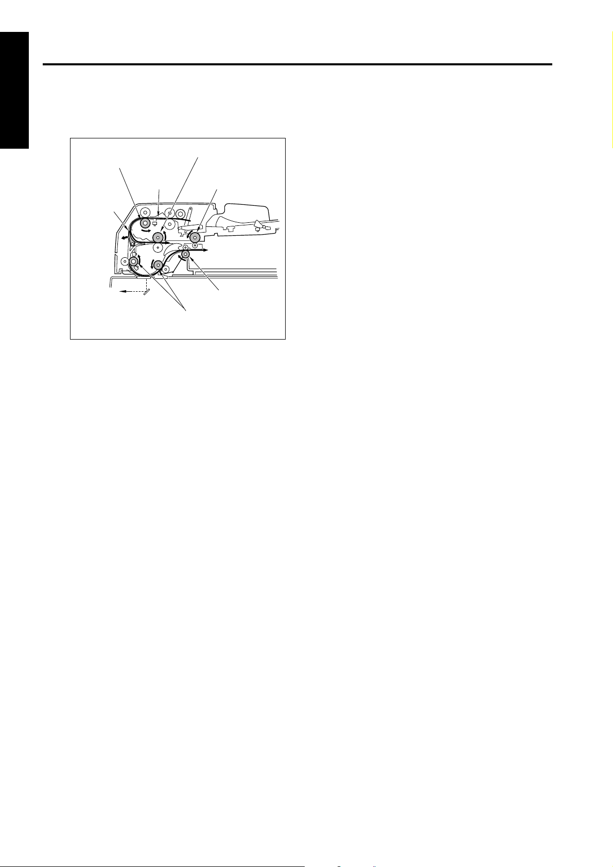
EDH-4/EDH-7
1 OUTLINE
next original is conveyed to the reversal section
if there is one.
[3] Mixed original copy mode
The mixed original copy mode supports both the
same series original and different series origi-
Registration roller
Next original
Reversal roller
Original exit
reversal roller
nals, and the size of the original is determined by
the ON interval of the original registration PS/1
(PS304). In single side original copy mode (with
out AMS) and double side original copy mode,
Reverse gate
the conveyance path of original is same as nor-
mal conveyance path. In single side original copy
mode (with AMS), the conveyance path of origi-
nal is same as that in double side original copy
mode.
For details on size detection, refer to section [5]
Original exit roller
Original Size Detection Control in Section 2. Unit
Explanation.
Conveyance roller
[4] Z fold original copy mode
In the Z fold original copy mode, the length of the
original is determined by the ON interval of the
original registration PS/1 (PS304).
The length is detected for the first sheet of orig-
inal. The conveyance path of the original is the
same as the single side original copy mode and
the double side original copy mode.
1-6
Page 77

2
UNIT EXPLANATION
2 UNIT EXPLANATION
Page 78

2 UNIT EXPLANATION
Blank page
Page 79

EXTERNAL SECTION
[1] Composition
Jam access cover
EDH-4/EDH-7
Original feed unit
Original feed tray
Original exit tray
2 UNIT EXPLANATION
[2] Mechanism
Mechanism Method
Jam removal *1Open / close cover
Original feed unit
Platen guide
*1 Jam removal
Remove the jammed original in the paper feed
section by opening Jam access cover.
Jam access cover
Remove the jammed original in the reversal section by opening Jam access cover and paper
feed unit.
Jam access cover
Original feed unit
Remove the jammed original in the conveyance
section by opening Platen guide.
Platen guide
2-1
Lock
Page 80

EDH-4/EDH-7
ORIGINAL FEED / CONVEYANCE / EXIT SECTION
[1] Composition
Double feed prevention roller
2 UNIT EXPLANATION
[2] Mechanism
Original feed Pickup roller
Double feed prevention
Original conveyance
Original exit Original exit roller
Original conveyance path selection *1
Pickup roller
Original feed roller
Registration roller
Reverse gate drive SD
(SD301)
Exit gate drive SD (SD302)
Pressure roller release SD
(SD303)
Mechanism Method
Original feed roller
Double feed prevention
roller
Original conveyance roller
(two)
Reverse gate
Original conveyance motor (M302)
Original feed MC (MC301)
Original feed motor (M301)
Original feed tray
Original exit tray
*1 Original conveyance path selection
During the double side copy mode, the original
conveyance path is selected at the reverse gate
in order to flip the original over to the other side,
and the original is conveyed to the reversal sec-
tion. The reverse gate drive SD (SD301) is
turned ON / OFF to switch between the reversal
section and the original exit section.
Reverse gate
Original reverse
and feed
Original exit path
Reversal roller
Original exit reversal roller
Original exit gate
selection *2
Original stopper *3 Original stopper actuator
(EDH-7)
Reverse gate
Reverse gate drive SD
(SD301)
2-2
Page 81

EDH-4/EDH-7
*2 Original exit path switching
During the double side copy mode, the up / down
movement of the original exit gate determines
whether to eject the original, or to feed the original to the reversal section to scan it again.
The exit gate drive SD (SD302) turns ON / OFF
during the double side copy mode. To scan the
back side, the original exit gate goes down to
convey the original to the reversal section. When
both sides of the original are read, the original
exit gate lifts to exit the original to the original exit
tray.
Original exit gate
Original exit gate
*3 Original stopper (EDH-7)
When placing originals on the paper feed tray,
the paper feed ability may be lowered if the originals are excessively inserted into the paper feed
section. To prevent such affair, an original stopper actuator is mounted in the paper feed
entrance section.
The original stopper actuator is driven by the
reverse gate SD (SD301) and the setting and
releasing are executed in conjunction with the
open/close operation of the reverse gate.
Original stopper actuator
Reverse gate
Original stopper actuator
Reverse gate
2 UNIT EXPLANATION
Exit gate drive SD
(SD302)
Reverse gate drive SD
(SD301)
df3222001
2-3
Page 82

EDH-4/EDH-7
[3] Original Feed / Conveyance / Scan
Control
24V
SCDBPRCB
24V
24V
24V
24V
DRIVE
SIG
S.G
SIG
S.G
SIG
S.G
SIG
S.G
FM CONT
SIG
P.G
A
A
B
B
A
A
B
B
5V
5V
5V
5V
2 UNIT EXPLANATION
PS304
PS305
PS306
PS307
PS308
MS301
24V2
P.GND
S.GND
DCPS
DF_M1_CLK
DF_M1_F/R
DF_M1_EN
DF_M1_M1
DF_M1_M2
DF_M1_I1
DF_M1_I2
DF_M1_
RETURN
DF_M2_CLK
DF_M2_F/R
DF_M2_EN
DF_M2_M1
DF_M2_M2
DF_M2_I1
DF_M2_I2
DF_M2_
RETURN
DF_FAN_CONT
DF_CL_CONT
DF_M_RESET
5V2
3.3V
S.G
5V
SIG
S.G
5V
SIG
S.G
5V
SIG
S.G
5V
SIG
S.G
5V
SIG
S.G
24V
24V
DF_M2_MOI
DF_FAN_SC_SIG
PS301_SIG
PS302_SIG
PS303_SIG
PS304_SIG
PS305_SIG
PS306_SIG
PS307_SIG
PS308_SIG
PS311_SIG
M
301
M
302
MC301
PS301
PS302
PS303
PS311
FM
301
Original feed is performed by the pickup roller
and original feed roller driven by M301 (original
feed). Original conveyance is performed by the
original conveyance roller driven by M302. Original is fed when MS301 (cover open / close MS)
and PS311 (ADF open / close PS) are turned
ON.
Each of these features is controlled by PRCB
(printer control board) and driven by SCDB
(scanner drive board).
2-4
Page 83

EDH-4/EDH-7
1. Operation
a. Pressing original against roller and pre-feed-
ing original
(1) Pre-feeding the first sheet of original
By pressing the Start button, M301 (original
feed) rotates backwards at high speed (MC301
(original feed MC) is ON) to raise the original
pressing plate. Since M301 rotates backward at
high speed, the original feed starts by the action
of the pick up roller and the original feed roller.
M301 stops when a specified time has passed
after the original has turned PS304 (original registration PS/1) ON.
(2) Pre-feeding the second and subsequent origi-
nals
When the currently scanned original is conveyed
and PS304 (original registration /1) turns OFF
during the single side original copy mode, M301
(original feed) rotates backward at high speed
(MC301 (original feed MC) is ON), the prefeeding of the next original starts. During the double
side original copy mode, M301 rotates backward
at high speed after a specified time when the
scanning of the back side of the first sheet of original has completed, and the prefeeding of the
next original starts. M301 stops after a specified
time after the original has turned PS304 ON.
b. Original conveyance operation
When the control signal is received from the
main body after the pre-feeding operation of the
original has completed, M301 (original feed)
rotates forward at high speed (MC301 (original
feed MC) is ON). The registration roller rotates
and the original is conveyed at high speed.
The forward rotation of M301 releases the pressure on the original pressing plate.
During the single side original copy, the conveyance switches to low speed when the specified
time has passed after PS305 (original registration /2) has turned ON. During the double side
original copy, the reverse gate opens and the
original passes through the reverse gate to be
conveyed to the reversal section at high speed.
(For details on reverse and conveyance control,
refer to [4] Original Reverse and Conveyance
Control.)
c. Scan operation
(1) Single side original copy mode
The low-speed rotation of M302 (original conveyance motor) starts in the same timing as the
conveyance procedure described above, and
the original is conveyed by the conveyance
roller. The scanning starts when the specified
time has passed after PS306 (original conveyance) has turned ON.
(2) Double side original copy mode
The back side of the original is scanned first, then
the front side. The scanning procedure is the
same for both sides. M301 (original feed) rotates
backward at high speed (MC301 (original feed
MC) is ON), and the original is conveyed from the
reversal section to the read section. Then it
switches back to low speed when the specified
time has passed after PS305 (original registration /2) has turned ON. At the same time, M302
(original conveyance) starts rotating to scan the
original.
The scanning operation is the same as for the
single side original copy.
d. Scanning the last sheet of original
When PS301 (last original) turns OFF while
scanning is in progress, currently scanned original is processed as the last original. The prefeed of the original stops, and with PS302 (original setting) turned OFF, the original feed tray is
detected as empty. M301 (original feed) and
M302 (original conveyance) stop when the specified time has passed after the original has
passed through PS303 (original exit) and original
ejection has completed.
e. Original skew detection control
PS307 (original skew /F) and PS308 (original
skew /R) are provided to detect the inclined leading edge of the original during conveyance.
PS307 and PS308 are placed at the front and
back of the pre-scan conveyance path and determine the inclination in interval at which the leading edge of the original turns these switches ON.
A skewed image caused by original inclination is
corrected through image processing and image
data is writen.
2 UNIT EXPLANATION
2-5
Page 84

EDH-4/EDH-7
f. FM301 (original feed motor cooling fan) oper-
ation
FM301 is used to cool M301 so that M301 does
not overheat during operation.
(1) ON timing
At the start of DF.
(2) OFF timing
When M302 is OFF.
2. Signals
a. Input signal
(1) 24V (MS301 to SCDB)
2 UNIT EXPLANATION
Open / close detection signal of Jam access
cover.
[L]: Cover opened.
[H]: Cover closed.
(2) SIG (PS301 to SCDB)
Last sheet of original on the original feed tray
detected.
[L]: Original present.
[H]: No original.
(3) SIG (PS302 to SCDB)
No original on original feed tray detection signal.
[L]: Original present.
[H]: No original.
(4) SIG (PS303 to SCDB)
Original exit detection signal.
[L]: Original present.
[H]: No original.
(5) SIG (PS311 to SCDB)
ADF open / close detection signal.
[L]: ADF closed.
[H]: ADF opened.
(6) SIG (PS304 to SCDB)
Original detected at the entrance of the registration roller.
[L]: Original present.
[H]: No original.
(7) SIG (PS305 to SCDB)
Original detected for double side original copy
mode.
[L]: Original present.
[H]: No original.
(8) SIG (PS306 to SCDB)
Original detected before the scan position.
[L]: Original present.
[H]: No original.
(9) SIG (PS307 to SCDB)
Front side original skew detection signal.
[L]: Original present.
[H]: No original.
(10) SIG (PS308 to SCDB)
Rear side original skew detection signal.
[L]: Original present.
[H]: No original.
(11) DF_FAN_SC_SIG (FM301 to SCDB to PRCB)
FM301 abnormal operation detection signal.
[L]: FM301 normal.
[H]: FM301 abnormal.
(12) DF_M1_CLK (PRCB to SCDB)
M301 control clock.
(13) DF_M1_F/R (PRCB to SCDB)
M301 drive direction control signal.
(14) DF_M1_EN (PRCB to SCDB)
M301 drive IC enable signal.
(15) DF_M1_M1 (PRCB to SCDB)
M301 drive control signal.
(16) DF_M1_M2 (PRCB to SCDB)
M301 drive control signal.
(17) DF_M1_I1 (PRCB to SCDB)
M301 drive electric current control signal.
(18) DF_M1_I2 (PRCB to SCDB)
M301 drive electric current control signal.
(19) DF_M1_RETURN (PRCB to SCDB)
M301 return signal.
(20) DF_M2_CLK (PRCB to SCDB)
M302 control clock.
(21) DF_M2_F/R (PRCB to SCDB)
M302 drive direction control signal.
(22) DF_M2_EN (PRCB to SCDB)
M302 drive IC enable signal.
(23) DF_M2_M1 (PRCB to SCDB)
M302 drive control signal.
(24) DF_M2_M2 (PRCB to SCDB)
M302 drive control signal.
(25) DF_M2_I1 (PRCB to SCDB)
M302 drive electric current control signal.
(26) DF_M2_I2 (PRCB to SCDB)
M302 drive electric current control signal.
(27) DF_M2_RETURN (PRCB to SCDB)
M302 return signal.
(28) DF_M_RESET (PRCB to SCDB)
M301 / M302 drive reset signal.
(29) DF_FAN_CONT (PRCB to SCDB)
FM301 drive control signal.
(30) DF_CL_CONT (PRCB to SCDB)
MC301 drive control signal.
2-6
Page 85

EDH-4/EDH-7
b. Output signal
(1) A, A
(SCDB to M301)
M301 A phase drive signal.
(2) B, B
(SCDB to M301)
M301 B phase drive signal.
(3) A, A
(SCDB to M302)
M302 A phase drive signal.
(4) B, B
(SCDB to M302)
M302 B phase drive signal.
(5) DRIVE (SCDB to M301)
MC301 ON/OFF drive signal.
[L]: MC301 ON
[H]: MC301 OFF
(6) FM CONT (SCDB to FM301)
FM301 ON/OFF drive signal.
[L]: FM301 OFF
[H]: FM301 ON
(7) DF_M2_MOI (SCDB to PRCB)
M302 MOI signal.
(8) SIG (SCDB a PRCB)
FM301 operation detection signal.
(9) PS301_SIG (SCDB to PRCB)
See: Input signal.
(10) PS302_SIG (SCDB to PRCB)
See: Input signal.
(11) PS303_SIG (SCDB to PRCB)
See: Input signal.
(12) PS304_SIG (SCDB to PRCB)
See: Input signal.
(13) PS305_SIG (SCDB to PRCB)
See: Input signal.
(14) PS306_SIG (SCDB to PRCB)
See: Input signal.
(15) PS307_SIG (SCDB to PRCB)
See: Input signal.
(16) PS308_SIG (SCDB to PRCB)
See: Input signal.
(17) PS311_SIG (SCDB to PRCB)
See: Input signal.
[4] Original Reversal and Conveyance
Control
24V
5V
PS304
PS305
MS301
24V2
P.GND
S.GND
DCPS
DF_M1_CLK
DF_M1_F/R
DF_M1_EN
DF_M1_M1
DF_M1_M2
DF_M1_I1
DF_M1_I2
DF_M1_
RETURN
DF_M2_CLK
DF_M2_F/R
DF_M2_EN
DF_M2_M1
DF_M2_M2
DF_M2_I1
DF_M2_I2
DF_M2_MOI
DF_M2_
RETURN
DF_SD1_CONT
DF_SD2_CONT
DF_SD3_CONT
DF_M_RESET
5V2
3.3V
S.G
SIG
S.G
5V
SIG
S.G
24V
24V
PS303_SIG
PS304_SIG
PS305_SIG
The original exit gate which switches the original
exit path is driven by SD302 (exit gate drive). The
reverse gate, which switches the original feed
path during double side original copy mode, is
driven by SD301 (reverse gate drive). SD303
(pressure roller release) releases the pressure
on the original exit reversal roller.
Ejection of the original and conveyance to the
reversal exit are performed by M302 (original
conveyance) which rotates the conveyance
roller and original exit roller. M301 (original feed)
drives the reversal roller and original exit reversal roller to convey the original to the reversal
section. Each of these features is controlled by
PRCB (printer control board) and driven by
SCDB (scanner drive board).
24V
A
A
B
B
24V
24V
A
A
B
B
24V
DRIVE
5V
SIG
S.G
24V
DRIVE
24V
DRIVE
SCDBPRCB
M
301
M
302
SD301
PS303
SD302
SD303
2 UNIT EXPLANATION
2-7
Page 86

EDH-4/EDH-7
1. Operation
a. Original ejection operation
During the single side copy mode and when
copying the front side in the double side copy
mode, the original exit gate lifts upward because
SD302 (exit gate drive SD) is turned OFF. Therefore, scanned original is ejected to the original
exit tray by the action of the original exit roller.
PS303 (original exit PS) detects the original ejection.
b. Reversal operation for double side original
copy
2 UNIT EXPLANATION
(1) The first sheet of original
When PS304 (original registration /1) turns ON
and pre-feed of the original has completed,
SD301 (reverse gate drive) receives a signal
from the main body and turns ON to open the
reverse gate. M301 (original feed) rotates forward (MC301 (original feed MC) is ON), and the
registration roller, reversal roller, and original exit
reversal roller convey the original to the reversal
section at high speed, passing through the
reverse gate. M301 stops when a specified time
has passed after PS304 has detected the trailing
edge of the original. (The original is conveyed to
the reversal section until the trailing edge
crosses over the reverse gate.) During this time,
SD301 turns OFF and the reverse gate closes.
(2) Second and subsequent original
When PS305 (original registration /2) detects the
trailing edge of the front side of the first original,
SD301 (reverse gate drive) turns ON to open the
reverse gate.The second and subsequent originals are thus conveyed to the reversal section in
the same manner as the first original.
c. Feeding the back side
When the reversal operation for the double side
copy mode described above has completed,
high speed backward rotation of M301 (original
feed) (MC301 (original feed MC) is OFF) conveys the original to the read section by the action
of the reversal roller and the original exit reversal
roller. When M301 rotates backward, SD302
(exit gate drive) turns ON to lower the original exit
gate, and the original exit path switches from the
original exit tray to the reversal exit. When the
specified time has passed since PS305 (original
registration /2) is turned ON by detecting the
leading edge of the original, SD303 (pressure
roller release SD) turns ON temporarily accord-
ing to the original size. By SD303’s turning ON,
the pressure on the original exit reversal roller is
released. This enables the leading edge and the
trailing edge of the original to pass each other.
When a specified time has passed since the
back side of the original starts to be scanned,
SD303 turns OFF, at the same time, M301 has
been switched to low speed forward rotation
(MC301 is OFF). The original exit reversal roller
rotates in the reverse direction, and the original
is conveyed to the reversal exit again. As soon as
scanning of the back side of the original has completed, SD302 turns OFF, and after the predefined time, M301 is switched to high speed
rotation. It stops after the specified interval.
d. Feeding the front side of the original
The original which is conveyed to the reversal
section is conveyed to the read section again in
order to scan the front side. Since SD302 (exit
gate drive) is OFF, the scanned original is
ejected to the original exit tray.
2. Signals
a. Input signals
(1) DF_SD1_CONT (PRCB to SCDB)
SD301 ON/OFF control signal.
[L]: SD301 ON
[H]: SD301 OFF
(2) DF_SD2_CONT (PRCB to SCDB)
SD302 ON/OFF control signal.
[L]: SD302 ON
[H]: SD302 OFF
(3) DF_SD3_CONT (PRCB to SCDB)
SD303 ON/OFF control signal.
[L]: SD303 ON
[H]: SD303 OFF
b. Output signal
(1) DRIVE (SCDB to SD301)
SD301 ON/OFF drive signal.
[L]: SD301 ON
[H]: SD301 OFF
(2) DRIVE (SCDB to SD302)
SD302 ON/OFF drive signal.
[L]: SD302 ON
[H]: SD302 OFF
(3) DRIVE (SCDB to SD303)
SD303 ON/OFF drive signal.
[L]: SD303 ON
[H]: SD303 OFF
2-8
Page 87

EDH-4/EDH-7
[5] Original Size Detection Control
24V2
P.GND
5V2
S.GND
DCPS
PS304_SIG
PS309_SIG
PS310_SIG
VR301_SIG
SCDB
PRCB
3.3V
S.G
The size of the original placed in the original feed
tray is detected by PS309 (original size /2),
PS310 (original size /1), and VR301 (original
size VR).
Each of these features is controlled by PRCB
(printer control board) and driven by SCDB
(scanner drive board).
1. Operation
a. Normal copy mode
PRCB detects the original size from the combination of the following signals:
(1) Drum axis direction size detection
A guide plate is connected to VR301 (original
size VR) and the resistance value varies with the
position of the guide plate. This is used to determine the vertical dimension of the original.
(2) Original feed direction size detection
The horizontal dimension of the original is
detected with the ON/OFF combination of
PS309 (original size /2) and PS310 (original size
PS/1).
b. Mixed / Z fold copy mode original size detec-
tion
Size detection during mixed and Z fold copy
modes are performed as follows:
(1) Drum axis direction size detection
The vertical dimension of the largest original is
determined by the position of the guide plate.
SIG
S.G
SIG
S.G
3.3V
SIG
S.G
SIG
S.G
5V
5V
5V
PS309
PS310
VR301
PS304
(2) Original feed direction size detection
The ON interval of PS304 (original registration /
1) after the original passes the registration roller
is used to determine the horizontal dimension of
each original.
(3) Original feed direction size detection operation
When the original is fed from the registration
roller, in single side original copy mode(when
AMS is not used) and double side original copy
mode, the conveyance path of original is same
as normal conveyance path.
In single side original copy mode (when AMS is
used) and Z fold copy mode, the conveyance
path of original is same as that in double side
original copy mode, passing the reverse gate
and reverse section.
In each case, the ON interval of PS304 (original
registration /1) is measured and used to detect
the length of the original.
In single side original copy mode (when AMS is
used), the original is not read before magnification rate is decided. Therefore, the conveyance
path of original is same as that in duble side original copy mode, so that PS304 detects the length
of the original.
In Z fold original copy mode, the length of the first
original is detected.
PS304 (Original registration/1)
Registration roller
Reverse gate
Original exit reversal
roller
Reversal roller
2 UNIT EXPLANATION
2-9
Page 88

EDH-4/EDH-7
c. Allowed size combination
( : Same size, : Same series, : Different
series, X: Mixing prohibited, -: Not supported)
(1) AB series *1
2 UNIT EXPLANATION
*1 Memory switch in the key operator mode
(2) Inch series *2
Reference original (maximum-size
original detectable with guide plate)
A3 A4 B4 B5
A3
A4
B4
B5
A4R
A5
B5R
XX -
A5R
XXXXXXX -
B6R
XXXXXXX
-------
-------
A4R
A5
B5R A5R B6R
-----
-----
---
---
needs to be changed to use the inch series.
2. Signals
a. Input signals
(1) SIG (PS309 to SCDB)
Original horizontal dimension detection signal.
[L]: Original present.
[H]: No original.
(2) SIG (PS310 to SCDB)
Original horizontal dimension detection signal.
[L]: Original present.
[H]: No original.
(3) SIG (VR301 to SCDB)
Original vertical dimension detection signal.
b. Output signal
(1) PS309_SIG (SCDB to PRCB)
See: Input signal.
(2) PS310_SIG (SCDB to PRCB)
See: Input signal.
(3) VR301_SIG (SCDB to PRCB)
See: Input signal.
Reference original (maximumsize original detectable with
guide plate)
11 x 17
8.5 x 11
8.5 x 14
8.5 x 11R
8.5 x 5.5
8.5 x 5.5R
11 x 178.5
8.5 x 148.5 x
x 11
----
----
XXXXX
11R
8.5 x
5.5
8.5 x
5.5R
-
-
-
*2 Memory switch in the key operator mode
needs to be changed to use the AB series.
2-10
Page 89

3
DISASSEMBLY/ASSEMBLY
3 DIS./ASSEMBLY
Page 90

3 DIS./ASSEMBLY
This section explains how to disassemble and reassemble the machine.
When disassembling and reassembling the machine, follow the precautions given below.
1. Be sure the power cord has been unplugged from the wall outlet.
2. The disassembled parts must be reassembled following the disassembly procedure in reverse unless otherwise specified.
3. Care should be taken not to lose small parts. Care should also be
taken not to install small parts in wrong places.
4. Do not operate he machine before installing all the disassembled parts
completely.
5. Removal of some screws is prohibited in this section. Never loosen
them.
Page 91

EXTERNAL SECTION
EDH-4/EDH-7
[1] Removing the RADF
Caution:
Make sure power cord of the main unit has
been unplugged from the wall outlet.
a. Procedure
(1) Remove the rear cover. (See the external section
of the main body.)
(2) Remove two screws to detach the two stoppers.
ScrewsScrews
(4) Remove four connectors (CN612 to CN615) from
the scanner drive board (SCDB) on the main
body.
Connector
(CN614)
Scanner drive board
(SCDB)
Connector
(CN615)
Connector
(CN613)
Connector
(CN612)
(5) Remove four screws to detach the cable conduit.
3 DIS./ASSEMBLY
Stopper1 Stopper2
(3) Open the RADF to the upright position.
RADF
Cable conduit
Screws(4)
(6) Draw the cable to the top of the main body.
3-1
Page 92

EDH-4/EDH-7
(7) Close the RADF. Remove three screws to detach
3 DIS./ASSEMBLY
(8) Open the RADF to the upright position.
(9) Remove two screws to detach the spacer and
(10) Holding the RADF, remove two screws to detach
each of two fixing plates.
Fixing plate Fixing plate
Screw Screws(2)
attachment from the left fixing plate.
two fixing plates and remove the RADF from the
main body.
Caution: When fixing plates are removed, the
RADF may fall down to the rear side.
Be sure to hold the RADF.
[2] Reinstalling the RADF
Caution:
Make sure power cord of the main unit has
been unplugged from the wall outlet.
a. Procedure
(1) Place the RADF on the top of the main unit and
loosely secure each of the two fixing plates with
two screws.
(2) Secure the attachment and spacer to the left fix-
ing plate, and loosely secure it with two screws.
(3) Remove two screws to detach the original stop-
per plate (left).
Original stopper plate
Screw
(left)
Screw
2
(tighten temporarily)
Screw
(tighten temporarily)
Screws
(tighten temporarily)
Fixing
plate
Screw
Fixing
plate
Attachment
Spacer
Fixing
plate
Screws(2)
Spacer
Screw
Attachment
Fixing plate
Screw
(4) Follow the removal procedure in reverse, install
the cable conduit and four relay connectors
(CN612 to CN615).
3-2
Page 93

EDH-4/EDH-7
(5) Install two RADF positioning jigs in the mounting
holes of the original stopper plates (left).
(6) Close the RADF to mate the reference holes and
RADF positioning jigs.
(7) Install three screws to secure each of the two fix-
ing plates with three screws following the
removal procedure in reverse.
(8) Open the RADF and tighten all of the four screws
to secure the two fixing plates.
Reference hole (round)
Reference hole
(oval)
RADF positioning jigs
RADF positioning jigs
(11) Close the RADF and check whether both stopper
pieces on the RADF-side touch the slit glass.
Stopper piece Stopper piece
Screws(2)
Top cover
(left)
(12) If both stopper pieces do not touch the slit glass
at the same time, make adjustments using
adjusting screws A and B alternately.
(13) Perform steps 11 and 12 repeatedly until the two
stopper pieces touch the slit glass at the same
time.
3 DIS./ASSEMBLY
(9) Remove the RADF positioning jigs and install the
original stopper plate (left) with two screws.
(10) Remove two screws and uninstall the top cover
(left).
Adjusting screw B Adjusting screw A
(14) For further installation, follow the removal proce-
dure in reverse.
(15) Open and close angle of RADF can be changed
from 70 degrees to 40 degrees when the stopper
is attached to opposite direction.
3-3
Page 94

EDH-4/EDH-7
ORIGINAL FEED/CONVEYANCE/EXIT SECTION
[1] Replacing the Pickup Roller and Con-
veyance Roller Rubber
In the case of the EDH-4
Caution:
Make sure power cord of the main unit has
been unplugged from the wall outlet.
a. Procedure
(1) Open the Jam access cover.
(2) Remove three stop rings, shift each of the two
bearings outward and detach them.
(3) Remove the pickup roller assembly to detach the
pickup roller.
(4) Remove the pickup roller rubber from the pickup
roller.
3 DIS./ASSEMBLY
Stop ring
Bearing
Stop ring
Pickup roller
Pickup roller rubber
Bearing
Stop ring
(8) Remove the original feed roller rubber from the
original feed roller.
Jam access cover
Sensor arm
Original feed
roller
Stop ring
Gear
(with a pin)
Stop
ring
Original feed roller rubber
D-cut unit
Stop
rings
Bearing
Original feed roller
shaft
Paint mark
Pickup roller
Jam access
cover
(5) Remove four stop rings, and shift the gear (with
a pin) and bearing outward.
(6) Shift the original feed roller assembly to the left
until it stops and lift it up to remove it.
(7) Remove the gear (with a pin) and remove the
original feed roller.
(9) Reinstall the above parts following the removal
procedure in reverse.
Caution1: Make sure that the original feed roller
is installed in the correct direction.
Caution2: Install the D-cut shaft of the original
feed roller assembly while inserting it
in the receiver side.
Caution3: Make sure not to damage the sensor
arm during installation.
3-4
Page 95

EDH-4/EDH-7
In the case of the EDH-7
Caution:
Make sure power cord of the main unit has
been unplugged from the wall outlet.
b. Procedure
(1) Open the Jam access cover.
(2) Remove two stop rings, release the two bear-
ings.
(3) Detach the original feed roller unit.
Original feed roller unit
(4) Remove two stop rings and two bearings to
detach the pickup roller.
(5) Remove the pickup roller rubber from the pickup
roller.
(6) Remove a stop ring, two bearings and a spring to
detach the pickup roller.
(7) Remove the pickup roller rubber from the pickup
roller.
Arrow
Bearing
Stop ring
Pickup roller
Stop rings
3 DIS./ASSEMBLY
Stop rings
Bearings
df3223001
Spring
Bearings
Original feed
roller
Bearing
D-cut shaft
Paint mark
df3223002
(8) Reinstall the above parts following the removal
steps in reverse.
Caution1: Make sure that the original feed roller
and the pickup roller are installed in
the correct direction.
Caution2: Install the D-cut shaft of the original
feed roller unit while inserting it in the
receiver side.
Caution3: Make sure that the spring is hooked
in correct position during installation.
3-5
Page 96

EDH-4/EDH-7
[2] Cleaning the Cleaning Pad
Caution:
Make sure power cord of the main unit has
been unplugged from the wall outlet.
a. Procedure
(1) Open the Jam access cover.
(2) Remove one screw to detach the cleaning pad.
(3) Using a blower brush, clean the cleaning pad.
Cleaning pad
Registration idler
roller
Jam access cover
3 DIS./ASSEMBLY
[3] Replacing the Double Feed Preven-
tion Roller / Double Feed Prevention
Roller Rubber
Caution:
Make sure power cord of the main unit has
been unplugged from the wall outlet.
a. Procedure
(1) Open the Jam access cover.
(2) Open the retaining clip and remove the double
feed prevention roller.
(3) Remove the double feed prevention roller rubber
from the double feed prevention roller.
Jam access cover
Screw
(4) Reinstall the above parts following the removal
steps in reverse.
Double feed prevention roller rubber
Double feed prevention
roller
(4) Reinstall the above parts following the removal
procedure in reverse.
Caution: Make sure that the double feed pre-
vention roller is installed in the correct
direction.
3-6
Page 97

SERVICE MANUAL
FN-115/FN-7
2004.01
Ver. 1.0
Page 98

Page 99

CONTENTS
CONTENTS
SAFETY AND IMPORTANT WARNING ITEMS
Refer to the Di551/Di650/Di5510/Di7210
service manual on page ................................................ C-1
1. OUTLINE
FN-115/FN-7 PRODUCT SPECIFICATIONS.......... 1-1
CENTER CROSS SECTION ................................... 1-3
DRIVE SYSTEM DIAGRAM.................................... 1-4
[1] Paper Conveyance Drive ............................ 1-4
[2] Stacker Drive .............................................. 1-5
[3] Folding Drive (FN-7 only) ............................ 1-6
PAPER CONVEYANCE PROCESS .......................1-7
[1] Paper Conveyance Process ....................... 1-7
[2] Non-Sort Mode............................................ 1-8
[3] Sort, Group Mode ....................................... 1-9
[4] Sub-tray Mode ..........................................1-10
[5] Staple Mode .............................................. 1-11
[6] Booklet Mode (FN-7 only) .........................1-13
2. UNIT EXPLANATION
EXTERNAL SECTION ............................................ 2-1
[1] Composition ................................................2-1
[2] Mechanisms ................................................ 2-1
CONVEYANCE SECTION ...................................... 2-2
[1] Composition ................................................2-2
[2] Mechanisms ................................................ 2-3
[3] M1 (FNS Conveyance) Control ................... 2-7
[4] Gate Control................................................ 2-9
[5] M13 (Stacker Entrance) Control ............... 2-12
[6] M5 (Alignment Plate/Upper) Control ......... 2-14
[7] M15 (Alignment Plate/Lower) Control
(FN-7 only) ................................................ 2-15
[8] M2 (Roller Shift) Control ........................... 2-16
[9] M7 (Paper Exit Roller) Control .................. 2-17
[10] SD4 (Paper Exit Opening) Control............ 2-19
[11] M8 (Paper Exit Opening) Control.............. 2-20
STAPLER UNIT..................................................... 2-21
[1] Composition ..............................................2-21
[2] Mechanisms .............................................. 2-22
[3] Stapler Control ..........................................2-26
MAIN TRAY UNIT ................................................. 2-30
[1] Composition ..............................................2-30
[2] Mechanisms .............................................. 2-30
[3] Main Tray Up/Down Control...................... 2-31
FOLDING UNIT (FN-7 ONLY)............................... 2-32
[1] Composition ..............................................2-32
[2] Mechanisms .............................................. 2-33
[3] Folding-Unit Control ..................................2-34
1 OUTLINE
2 UNIT EXPLANATION
3 DIS./ASSEMBLY
3. DISASSEMBLY/ASSEMBLY
EXTERNAL SECTION ............................................ 3-1
[1] Removing and Reinstalling
the Rear Cover............................................3-1
[2] Removing and Reinstalling
the Front Cover ........................................... 3-1
[3] Removing and Reinstalling
the Top Cover .............................................3-1
Page 100

CONTENTS
1 OUTLINE
2 UNIT EXPLANATION
3 DIS./ASSEMBLY
[4] Removing and Reinstalling
the Paper Exit Cover................................... 3-2
[5] Removing and Reinstalling
the Main Tray .............................................. 3-2
[6] Removing and Reattaching
the Front Side Cover................................... 3-3
[7] Removing and Reinstalling
the Paper Exit Stopper Plate.......................3-3
PAPER FEED UNIT ................................................ 3-5
[1] Replacing a Paper Exit Roller
(Sponge Roller)........................................... 3-5
[2] Removing and Reinstalling
the Paper Exit Unit/Shift Unit ...................... 3-5
[3] Removing and Reinstalling
the Stacker/Stapler Unit .............................. 3-8
STAPLER UNIT..................................................... 3-11
[1] Exchanging the clincher (FN-7 only) ......... 3-11
[2] Removing and Reinstalling a Stapler
(For FN-115) ............................................. 3-12
[3] Removing and Reinstalling a Stapler
(For FN-7) .................................................3-12
MAIN TRAY SECTION.......................................... 3-14
[1] Removing and Reinstalling
the Up-Down Stay..................................... 3-14
[2] Exchanging the Up-Down Wire ................. 3-14
FOLDING UNIT (FN-7 ONLY)............................... 3-16
[1] Removing and Reinstalling
the Folding Unit......................................... 3-16
[2] Removing and Reinstalling
the Adjustment Cover ............................... 3-17
 Loading...