

Page 1

SETUP INSTRUCTIONS
FN-113
FINISHER
Di551/Di650
NOTES
•Keep all packing materials out of the reach of children.
•Before setting up, be sure to unplug the power cord of the machine.
4698-7744-03 © MINOLTA CO., LTD. Printed in Japan
Page 2
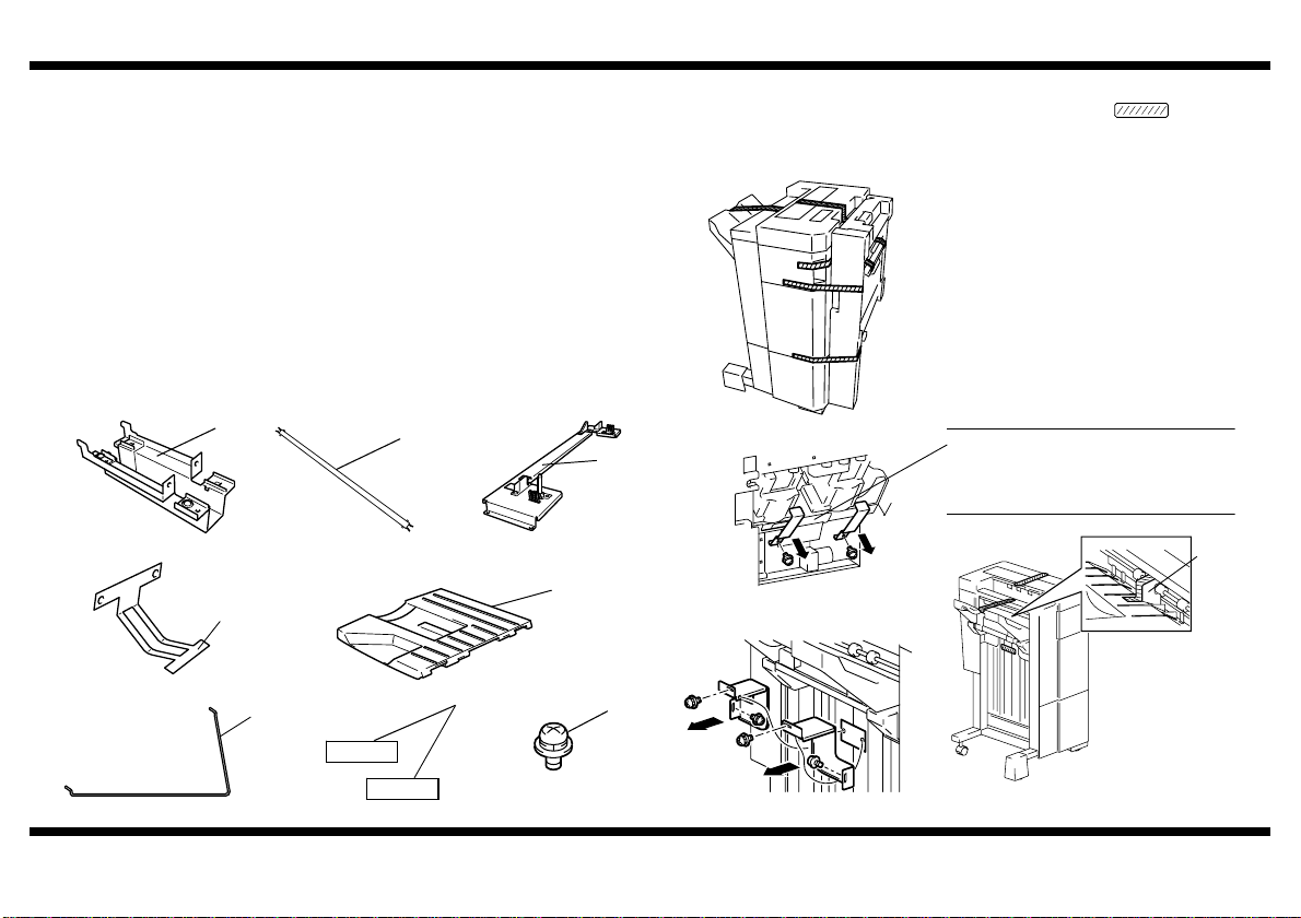
Components
NOTE
■
1. Feeder Attachment..................................................................................1
2. Pipe .........................................................................................................1
3. Fixing Bracket..........................................................................................2
4. Ground Plate ...........................................................................................1
5. Tray .........................................................................................................1
6. Wire Form................................................................................................1
7. Label........................................................................................................2
8. Screw ......................................................................................................8
9. Setup Instructions....................................................................................1
10. Cover.......................................................................................................1
FINISHER
Remove tape and fixing brackets.
: Tape
1. Open the vertical transport section of the
Finisher and remove tape and fixing brackets
from the Stapling Unit.
4698U003AA
4698-7744-03
1
4698U019AA 4698U002AA
2
C4611U005AA
5
4
4643U006AA
7
9646-0408-13
4643U010AA
6
4643U032AA
4698U004AA
3
Do not remove this part.
Use a mini-screwdriver to remove this
fixing bracket.
Cushion
4643U005AA
8
4698U020AA
4643U003AA
– 1 –
Page 3
NOTES
NOTE
•
Make sure that the Finisher is installed on a level surface.
•
Once the Finisher has been installed, do not move it unless absolutely necessary.
If it becomes absolutely necessary to move the Finisher, remove the Pipe both
from it and the machine. After the Finisher has been relocated, attach the Pipe
back again by following the steps given in “Attaching the Pipe.”
•
When moving the Finisher, press the side opposite to the Tray to prevent the Finisher from toppling over.
FINISHER
■
4698U021AA
4698U022AA
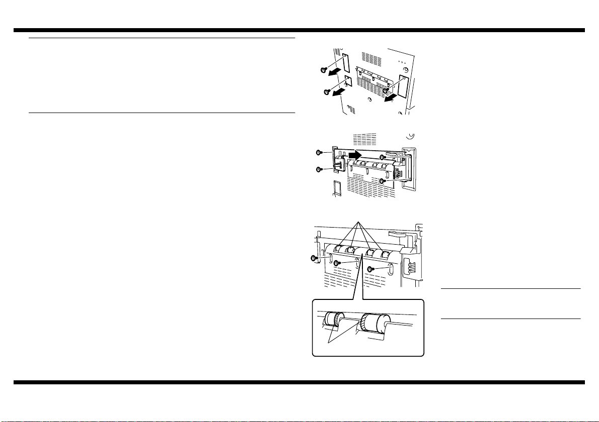
Attaching the Positioning Pin, Fixing Brackets, and Pipe
1. Remove the Left Covers (at three locations)
of the machine.
2. Install Fixing Bracket A.
Exit Rollers
3. Remove the Exit Roller Cover (three
screws).
4. Cut the inner Treaded Rubber Collars (4pcs.)
of each Exit Roller.
5. Reinstall the Exit Roller Cover (three screws)
which has been removed in step 3.
Make sure that the cover is doweled into
position.
4698-7744-03
Inner Side
4698U115AB
– 2 –
Page 4

4698U024AA
NOTE
4698U025AA
Ground Plate
6. Install the Feeder Attachment and Ground
Plate at the bottom on the left side of the
machine.
NOTE
Make sure of the correct direction of the
Feeder Attachment when installed. Check
that the rear of the Feeder Attachment is
hooked onto the inner side of the machine.
7. Fit one end of the Pipe into the mounting
guide on the Finisher Tray side and insert the
Pipe until a click is heard.
NOTE
At this time, do not press the Finisher up
against the machine, yet.
8. Slide the other end of the Pipe into the
Feeder Attachment installed in step 6.
FINISHER
■
4698U026AB
Adjusting the Position of the Finisher
1. Slowly move the Finisher toward the
machine and check the followings:
Alignment between the locations shown of
•
Fixing Bracket A mounted on the machine
and the stamped marks on the Finisher (at
the front and rear)
If the parts are not properly aligned with
each other , perf orm th ese st eps t o make an
adjustment.
2. Slowly move the Finisher away from the
machine and open the Vertical Transport
Section of the Finisher.
4698N025AB
4643U019AB
4698-7744-03
<When Removing the Pipe>
Using the tabs on the Finisher side, unlock the
Pipe and pull it out from the mounting guide.
Then, remove the Pipe together with the Feeder
Attachment installed in step 3. Next, pull the
Pipe out of the Feeder Attachment.
4698U009AA
3. Remove the Lower Front Cover (two screws)
of the Finisher.
4643U021AB
– 3 –
Page 5

FINISHER
4643U020AA
Locking Bolt
Adjusting Bolt
4643U022AB
4698U027AA
4698-7744-03
4. Pull up and remove the caster covers (two).
Locking Bolt
Adjusting Bolt
7. After the check has been made, tighten the
upper locking bolts of the casters (at four
places), while holding the lower adjusting
bolts in position.
8. Reinstall the parts which have been
removed.
4643U029AA
Connecting the Hookup Cord
5. Holding the lower adjusting bolt of the caster
in position, loosen the upper locking bolt.
Then, turn the lower adjusting bolt to adjust
the height.
■
Connect the two connectors of the Hookup
•
Cord of the Finisher at the locations shown.
Then, screw the cover of the Hookup Cord
with care not to allow any of the wires to be
wedged by the cover.
<Two in the rear>
If the Positioning Pin is higher
: Turn the bolt clockwise.
If the Positioning Pin is lower
4698U010AA
: Turn the bolt counterclockwise.
<Two at the front>
If Fixing Bracket A is higher
: Turn the bolt clockwise.
If Fixing Bracket A is lower
: Turn the bolt counterclockwise.
4698U011AA 4698U012AA 4698U028AA
6. Press the Finisher against the machine and
check that clearance between the two is
a
equal at points a and b.
NOTE
If the clearance at a is not equal that at b,
b
readjust with the casters.
– 4 –
Page 6

Installing the Tray and Wire Form
■
Install the Tray and Wire Form that come with
•
the Finisher at the locations shown.
Install the cover furnished with the Finisher.
•
(For the mounting screw, use the screw that
has been removed in step 1 on p. 2.)
4643U024AA
4643U017AA 4698U035AB
Affixing the Labels
■
Affix the labels that come with the Finisher.
1. Label (for the copier)
4698U014AA
Label (for the electronic document handler)
Cover
FINISHER
4643U034AA
4643U035AA
(For copier)
(For electronic document handler)
4698U015AA
4698-7744-03
– 5 –
Page 7

Setting the software DIP switches (For U.S.A. and Canada Only)
NOTE
■
1. Plug the power cord of the machine in the
power outlet and turn ON the Main Power
Switch and Power Switch.
2. Access the “25-mode” screen. (Refer to the
Service Manual for the procedure.)
3. Touch “Software SW setting.”
4656U049CA
FINISHER
4698U037CA
6. Touch to select the switch bit number.
7. Select “1” using the ▲ or ▼ key on the right
or directly enter it from the 10-Key Pad.
If the 10-Key Pad is used to enter the bit
number, first highlight the bit number on the
right and then enter the number
4698U036CA
4698-7744-03
4. Touch to select the DIP switch number.
5. Select “22” using the ▲ or ▼ key on the left
or directly enter it from the 10-Key Pad.
NOTE
If the 10-Key Pad is used to enter the DIP
switch number, first highlight the DIP switch
number on the left and then enter the
number
8. Select ON for the switch.
4698U038CA
– 6 –
Page 8

4698U036CA
FINISHER
9. Se lect the DIP switch numb er aga in.
10.Select “22” using the ▲ or ▼ key on the left
or directly enter it from the 10-Key Pad.
NOTE
If the 10-Key Pad is used to enter the DIP
switch number, first highlight the DIP switch
number on the left and then enter the
number
11.Touch to select the switch bit number.
Checking the Hole Positions for Hole Punch
■
1. Plug the power cord of the machine and turn
ON the Power Switch.
2. Load the 1st Drawe r with A4-size or Lettersize crosswise paper.
3. Touch “OUTPUT MENU.”
4698U032CA
4. Touch “PUNCH” to highlight it.
4698U039CA
4698U040CA
4698-7744-03
12.Select “2” using the ▲ or ▼ key on the right
or directly enter it from the 10-Key Pad.
NOTE
If the 10-Key Pad is used to enter the bit
number, first highlight the bit number on the
right and then enter the number
13.Select ON for the switch.
14.Touch “RETURN.”
15.Turn OFF and ON the Power Switch of the
machine.
4698U033CA
5. Touch the desired hole punch position.
6. Touch “OK.”
4698U034CA
7. P r ess the Start key.
4002O280CB
– 7 –
Page 9

4643U031AA
NOTE
FINISHER
8. Fold the copy in half to check that holes are
in correct alignment with each other.
Specifications: 0 ± 2 mm
NOTE
If the specifications are not met, adjust the
hole positions for Hole Punch.
Adjusting the Hole Positions for Hole Punch
■
1. Open the Top Cover of the Finisher and
loosen the screw that secures the Hole
Punch Guide Plate.
Slide the green handle to the front or rear to
adjust the position of holes for Hole Punch.
4643U025AA
2. Tighten the screw which has been loosened
in step 1.
Make a copy again and check for correct
hole positions. If the specifications are not
still met, readjust.
4643U031AA
3. After the adjustment has been completed,
close the Top Cover.
4698-7744-03
– 8 –
 Loading...