

Konica Minolta FK-514 Installation Manual
E-1
FK-514 Fax Kit
INSTALLATION MANUAL
A883-9552-00
Applied Machines: C658/C558/C458/C368/C308/C258
COLOR MFP: 65 ppm/55 ppm/45 ppm/36 ppm/30 ppm/25 ppm
Product Code: A79J/A79K/A79M/A7PU/A7PY/A7R0
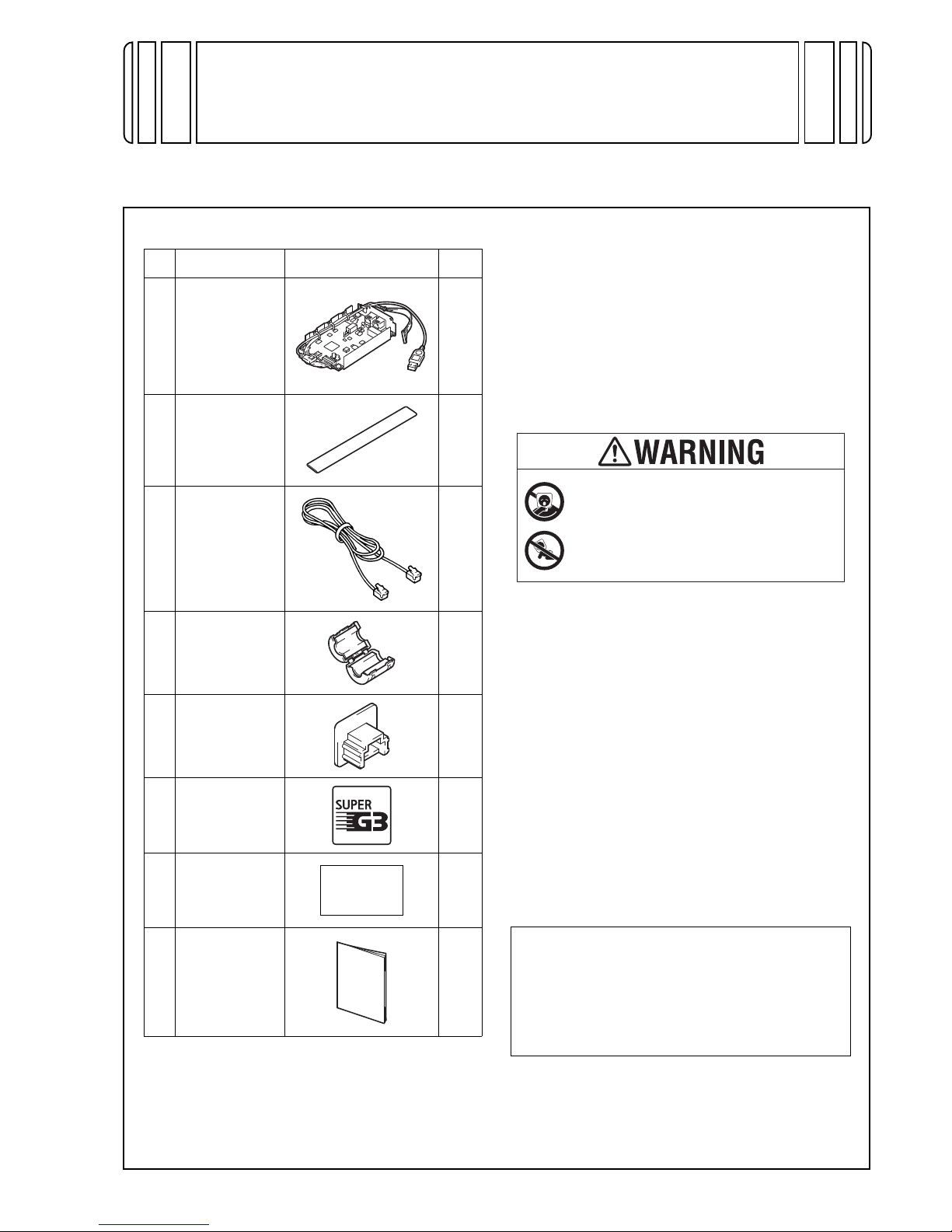
1. Accessory parts
*1
This part is used only when installing this option
to models C658/C558/C458.
*2
When installing a Line 1, use the two gaskets.
When installing a Line 2, use three of the four
gaskets supplied with the Fax Kits for the Line 1
and Line 2.
*3
Depending on the applicable marketing area, the
modular cable may have a ferrite core.
*4
Not included depending on the applicable marketing area.
Note:
• This manual provides the illustrations of the
accessory parts and machine that may be
slightly different in shape from yours. In that
case, instead of the illustrations, use the
appearance of your machine to follow the
installation procedure. This does not cause any
significant change or problem with the procedure.
• If none of the later steps instruct you to use the
parts including screw and cover that you
removed following the instructions described in
this manual, discard them.
2. Installation procedures
No. Name Shape Q’ty
1. Fax kit
1
2.
Gasket
*1*2
2
3. Modular cable
*3
1
4.
Ferrite core
*4
1
5. Modular cover
1
6. Label (Super
G3 label)
*4
1
7.
Label
*4
1 set
8. Installation
manual
1 set
<Installations to models C658/C558/C458>
Follow the installation procedures starting on page
E-2.
<Installations to models C368/C308/C258>
Follow the installation procedures starting on page
E-9.
Keep this bag away from babies and
children. Do not use in cribs, beds,
carriages, or playpens.
The thin film may cling to nose and
mouth and prevent breathing. This bag is
not a toy.
E-2
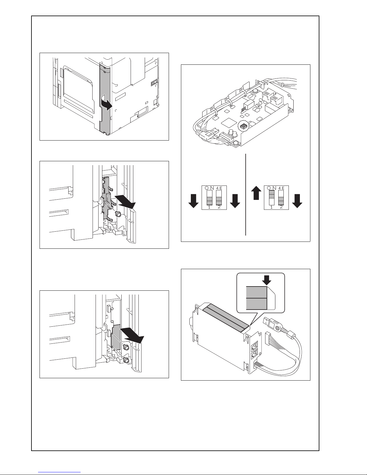
<Installations to models C658/C558/C458>
(1) Turn OFF the power switch and unplug the
power cord from the power outlet.
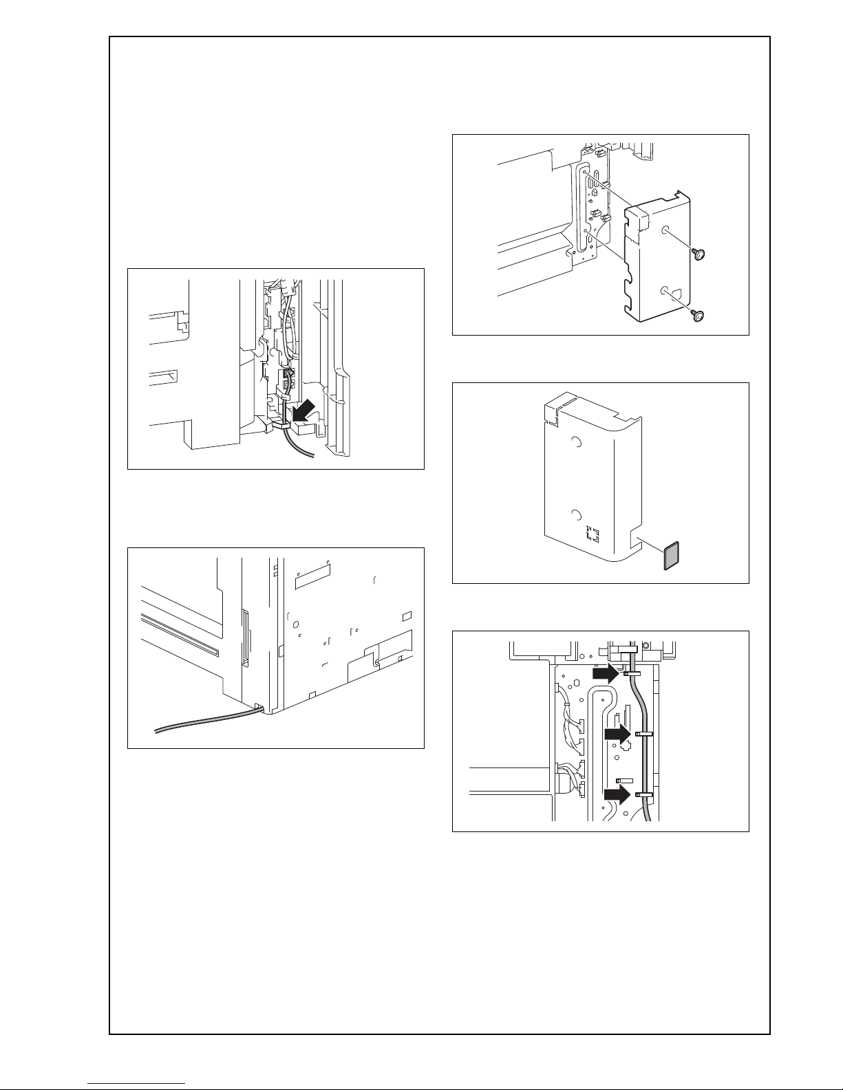
(2) Open the rear right cover.
(3) Remove the connector cover at the lower portion
inside the cover. (One screw)
(4) Remove the shield cover (FAX1) from the lower
under side, inside the door. (Two screws)
Note:
When installing a second fax kit, remove the shield
cover (FAX2) from the upper side.
(5) Make sure that the fax kit switch keys are placed
in positions as shown in “Line 1” below.
Note:
When installing a second fax kit, flip the fax kit
switch keys into positions as shown in “Line 2”
below.
(6) Attach the two supplied gaskets on the under-
side of the fax kit (Line1) as shown in the illustration.
<Line 1> <Line 2>
E-3
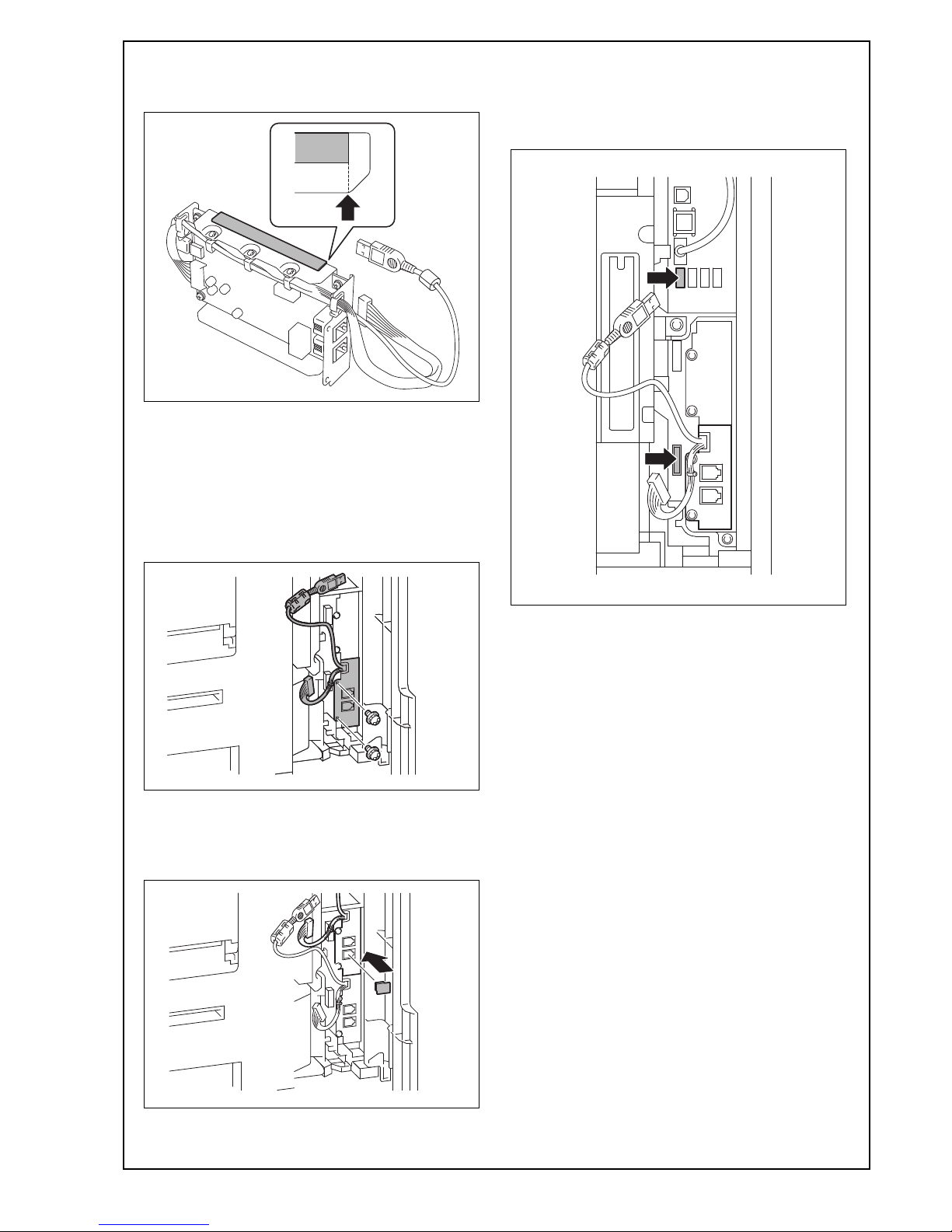
<Only when adding Line 2>
(7) Attach one supplied gasket on the top of the fax
kit (Line 1) as shown in the illustration.
(8) Insert the fax kit into the under socket (FAX1)
and secure it with the two screws removed in
step (4).
Note:
• Be careful not to pinch the harness between
plates.
• When installing a second fax kit, insert the FAX
kit into the upper socket (FAX2).
Note:
When installing a second fax kit, insert the supplied modular cover into the modular jack (TEL) for
“Line-2.”
(9) Connect each of the two connectors of the fax kit
to the corresponding port of FAX1.
Note:
When installing a second fax kit, connect the two
connectors to respective ports of FAX2.
E-4
(10) Route the fax kit harness and the USB cable as
shown in the illustration below.
<Line 1>
<Line 2>
(11) Reinstall the connector cover that has been
removed in step (3).(One screw)
Note:
• Fit the connector cover protrusion in the portion
of the machine shown in the illustration below.
• Be careful not to pinch the harness.
• Wind the USB cable of the Line 2 around the
two protrusions as shown in the illustration.
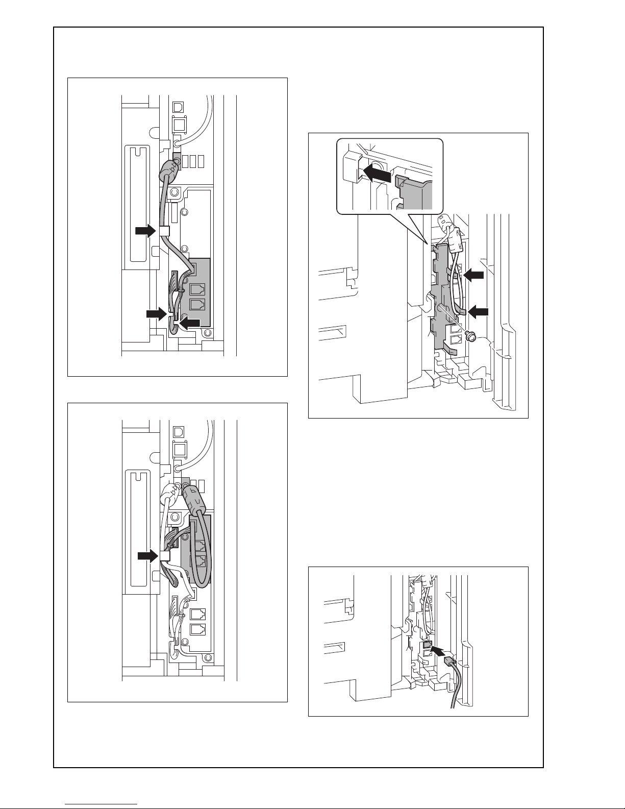
<Routing of the modular cable>
a. When the ferrite core is not installed to the
supplied modular cable
(1) Insert the supplied modular cable in the modular
jack (LINE).
Note:
If the user is connected with a key telephone system or a private branch exchange (PBX), do not
connect the modular cable to where other than an
analog line.
E-5
<Only when using the telephone line>
(2) Insert the modular cable of the telephone line to
the modular jack (TEL) of the fax kit (Line 1).
<Only when installing line 2>
(3) Insert the supplied modular cable in the modular
jack (LINE).
Note:
If the user is connected with a key telephone system or a private branch exchange (PBX), do not
connect the modular cable to where other than an
analog line.
(4) Place the modular cable in the harness guide.
<When adding no paper feed options/desk or when
using the Desk DK-705>
(5) Pass the modular cable into the hole in the lower
portion of the rear right cover.
<When using the Paper Feed Cabinet PC-415/PC215/PC-115 or desk DK-510>
(5) Perform the following steps.
a) Remove the rear right cover from the paper
feed cabinet or the desk. (Two screws)
b) Remove the knockout from the rear right cover
using nippers.
c) Route the modular cable through the three wire
saddles.
 Loading...