

Page 1

SERVICE MANUAL
Models
7115F/7118F
Fax Unit (FK-117)
APRIL 2002
FSM-7115F/7118F
KONICA BUSINESS TECHNOLOGIES, INC.
Page 2

Page 3

7115F/7118F
SERVICE MANUAL
APRIL 2002
Fax Unit (FK-117)
Page 4

IMPORTANT NOTICE
Because of the possible hazards to an inexperienced
person servicing this equipment, as well as the risk of
damage to the equipment, Konica Business Technologies strongly recommends that all servicing be performed by Konica-trained service technicians only.
Changes may have been made to this equipment to
improve its performance after this service manual was
printed. Accordingly, Konica Business Technologies,
Inc., makes no representations or warranties, either
expressed or implied, that the information contained in
this service manual is complete or accurate. It is understood that the user of this manual must assume all risks
or personal injury and/or damage to the equipment while
servicing the equipment for which this service manual
is intended.
Corporate Publications Department
© 2002, KONICA BUSINESS TECHNOLOGIES, INC.
All rights reserved.
Printed in U.S.A.
Page 5

CONTENTS
1. Specificatio ns ... ....... ........ ........ ....... .... ........ ....... ........ ........ ....... .... ........ ....... .....1
2. Panel Desc rip ti on . ... ........................... ........................... ............... .... ............... .4
3. FAX CPU BLOCK DIAGRAM ..........................................................................9
4. ASSEMBLY / DIASSEMBLY ...........................................................................11
4-1. Fax Control ler Board Assem b ly and Disassem bl y ....................... ............1 1
(1) With Printer Controller Board ...........................................................11
(2) Without Pri nte r Co nt rol ler Board ............... .... .... ............... .... ............1 4
4-2. NCU Controller Board Assembly / Disassembly ......................................18
4-3. PWB-C Board Assembly / Disassembly ..................................................20
(1) With Fax Cont rol le r Board ..... .... .... ... ................ .... ... ................ ... .... .20
(2) With Fax and Printer Controller Board .............................................23
(3) With Printer Controller Board ...........................................................26
4-4. PWB-A Board Assembly / Disassembly ..................................................29
(1) With Fax or Printer Controller Board ...............................................29
4-5. Speaker and Ba tte ry Asse mb ly / Dis ass em b ly . .... ............... .... .... .... ........31
4-6. Fax Panel As se mbly / Disassemb ly .................. ............................... ........34
5. ADJUSTMENT ............ .... .... .... ............... .... .... ... ................ .... ... .... .... ............... .35
5-1. ADJUST JUMPER SWITCH ON NCU BOARD .......................................35
5-2. Upgrading Fax Co nt rol le r Firm war e ....... ... .... ................ ... .... ............... .... .36
(1) Upgrading Proc e dur e Using RS- 2 32C Inte rfa ce ............. .... .... ... .....36
(2) Upgrad in g P roc edure Using Teleph on e Li ne
(from fax mach in e to fax ma ch in e) ... .... .... .... ............... .... .... ............3 8
(3) Action Take n When Firm wa r e Upg rad in g Fai ls ................... .... ... .....40
(4) Upgrading Proc e dur e Using RS- 2 32C Inte rfa ce ............. .... .... ... .....41
6. Service Mod e Fun c tion ...................... .... ............... .... ............... ................ ... .....43
6-1. Descriptio n .......... ............ ........... ........ ........... ............ ........... ............ ........43
(1) HOW TO ENTER INTO SERVICE MODE ....................... ............... .43
(2) KEY DEFINITION ............................................................................43
(3) FUNCTIO N ITEMS ..........................................................................44
(4) Setting Proce du re ....... ............... .... ... ................ .... ... .... ............... .... .44
6-2. SERVICE’S CHOICE ...............................................................................45
(1) MARKETING AR EA ............................................. ............... ............46
(2) SHIPMENT DESTINATION .............................................................47
(3) MAINTENANCE COUNTER ............................................................47
(4) IU LIFE STOP MODE ......................................................................48
(5) ID ADJUST ......................................................................................48
(6) VG ADJUST ...................... ............... ................ ............... ............... .48
(7) LEADING EDGE ERASE .............. ............... ............... ............... .....49
(8) TRAILING EDGE ERASE ............................. ............... ............... .....49
(9) VERTICAL EDG E E RASE . ............... .... ................ ... ................ ... .....49
(10) LOOP ADJUST (TRAY1), (TRAY 2-5), (BYPASS) ..........................49
(11) PRIORITY FLS ................................................................................50
(12) TX SPEED .......................................................................................50
(13) RX SPEED ......................................................................................50
(14) TX LEVEL ........................................................................................50
(15) RX LEVEL .......................................................................................51
iii
Page 6

(16) DTMF LEVEL ..................................................................................51
(17) CNG LEVEL .............................. ............... ............... ........................5 1
(18) CED LEVEL .....................................................................................52
(19) ECM MO DE .... ............... ................ .............................. ............... .....52
(20) CODING SCHEME ............................................... ............... ............52
(21) REPORT DESTINATION ................................................................53
(22) TONER EMPTY REPORT .............................................................. .54
(23) IU LIFE REPORT .......... .......................................... ........................54
(24) MAINTENANCE REPORT ..............................................................54
(25) PROTOC OL REPORT .............. ............... .... ............... .... ............... .54
(26) CUSTOMER ID .................................................... ...........................54
6-3. ADJUST ....... ........... ............ ....... ............ ........... ............ ........... ........... .....5 5
(1) PRN MAIN REGIST Ad1 .................................................................55
(2) PRN SUB REG IST Ad2 .............................................................. .....56
(3) CCD M AIN ZOOM Ad3 ....................................................................56
(4) CCD SUB ZOOM Ad4 .....................................................................57
(5) CCD MAIN REGIST Ad5 ... ..............................................................57
(6) CCD SUB REGIST Ad6 ...................................................................58
(7) ADF SUB ZOOM Ad7 ......................................................................58
(8) ADF MAIN REGIST Ad8 ..................................................................59
(9) ADF SUB REGIST Ad9 ...................................................................59
(10) ATDC GAIN Ad10 ......................................... ...................................60
(11) Model Set tin g Ad1 1 .... ............... .... ... .... ................ ... .... ............... .... .60
(12) Serial number Ad12 ....................... ... ................ .... ............... .... ........60
6-4. COUNTER ... ................... ................... ................... ................... ................ 61
(1) Total Coun ter ...... ............... .... ............... ................ ... ................ ... .....61
(2) Size Counter ... .... .... .... ............... .... ... ................ .... ... .... ............... .... .61
(3) PM counte r ................. ............... ............... ............... ........................61
(4) Maintenanc e coun te r ......... .... ............... .... .... .... ............... .... .... ........62
(5) Supplies Life C ount er ............ ............... .... .... ............... .... .... ............62
(6) Applicati on Cou nter ........... .... ............... ................ ... ................ ... .....62
(7) Misfeed Counte r . .... ............... .... .... ... ................ .... ... ................ ... .... .62
(8) Trouble co u nte r .......... ... ................ ... ................ ............... .... ............6 3
(9) Paper Size Counter .........................................................................64
6-5. Display . ............... ................ ............... ............... ............ ............... ............ 6 5
6-6. FAX SET ..................................................................................................66
(1) PAPER FEED TEST ................................. .......................................66
(2) PROCESS CHECK .........................................................................66
(3) ATDC SENSOR ADJUST .............. .......................................... ........67
(4) PRINT TEST PATTERN ..................................................................67
(5) ADF FEED TEST .............................................................................67
(6) COPY ADF GLASS AREA ..............................................................68
(7) CCD M OVE T O HOME ...................................................................68
(8) UPLOAD FIRMWARE ......................................................... ............68
(9) FAX RES. COPY TEST ...................................................................68
6-7. SOFT SWITCH ........................................................................................69
6-8. REPORTING ........................................................................................... 70
iv
Page 7

(1) SERVICE DATA LIST ......................................................................70
(2) ERROR CODE LIST .............. .......................................... ................73
(3) T.30 PROTOCOL LI ST .. .... .... .... ............... .... .... .... ............... .... ... .... .74
6-9. Administrator number registration ............................................................77
6-10.Fixed z oo m change ............ ............... ............... ............... .... ............... .....78
6-11.FACTORY TEST .....................................................................................79
6-12.CLEAR DATA ................. .......................................... ...............................79
(1) DRAM CLEAR ....................... ............... ................ ...........................79
(2) SRAM CLEAR ............... ................ ... ................ ............... ............... .79
(3) TOTAL COUN T ................. .... ............... .... ............... .... ............... .....79
(4) PM COUNTER .................. ............... ............................... ............... .79
(5) MEMORY CLEAR ...........................................................................80
(6) TOTAL CLEAR ...................... .... ............... ............... .... ............... .... .80
6-13.SECURITY ..............................................................................................81
(1) Total Coun ter coun ti ng .. ................ ... ................ ............... .... ............8 1
(2) Size counter count ing .................... ... .... ................ ... .... .... ............... .82
(3) Plug-in coun te r cop ying En ab le /Dis a bl e ........... ............... .... .... ........82
(4) Machine co un te r ............ .... ............... .... ................ ............... .... ........82
7. Soft Switch Set ................................................................................................83
7-1. Descriptio n .......... ............ ........... ........ ........... ............ ........... ............ ........83
7-2. Default setting ..........................................................................................83
(1) Country for each Marketing area .......... ................ ... .... ............... .... .83
7-3. Default softs w itch setting for ea ch M ark e t ar ea .... ............... .... ............... .84
7-4. Soft Switch definition ...............................................................................86
(1) SOFT SWITCH: 01 ..........................................................................86
(2) SOFT SWITCH: 02 ..........................................................................87
(3) SOFT SWITCH: 03 ..........................................................................88
(4) SOFT SWITCH: 04 ..........................................................................89
(5) SOFT SWITCH: 05 ..........................................................................90
(6) SOFT SWITCH: 06 ..........................................................................91
(7) SOFT SWITCH: 07 ..........................................................................92
(8) SOFT SWITCH: 08 ..........................................................................93
(9) SOFT SWITCH: 09 ..........................................................................94
(10) SOFT SWITCH: 10 ..........................................................................95
(11) SOFT SWITCH: 11 ..........................................................................96
(12) SOFT SWITCH: 12 ..........................................................................97
(13) SOFT SWITCH: 13 ..........................................................................98
(14) SOFT SWITCH: 14 ..........................................................................99
(15) SOFT SWITCH: 15 ..........................................................................100
(16) SOFT SWITCH: 16 ..........................................................................100
(17) SOFT SWITCH: 17 ..........................................................................101
(18) SOFT SWITCH: 18 ..........................................................................102
(19) SOFT SWITCH: 19 ..........................................................................103
(20) SOFT SWITCH: 20 ..........................................................................104
(21) SOFT SWITCH: 21 ..........................................................................105
(22) SOFT SWITCH: 22 ..........................................................................106
(23) SOFT SWITCH: 23 ..........................................................................107
v
Page 8

(24) SOFT SWITCH: 24 ..........................................................................107
(25) SOFT SWITCH: 25 ..........................................................................108
(26) SOFT SWITCH: 26 ..........................................................................109
(27) SOFT SWITCH: 27 ..........................................................................110
(28) SOFT SWITCH: 28 ..........................................................................111
(29) SOFT SWITCH: 29 ..........................................................................112
(30) SOFT SWITCH: 30 ..........................................................................113
(31) SOFT SWITCH: 31 ..........................................................................114
(32) SOFT SWITCH: 32 ..........................................................................114
(33) SOFT SWITCH: 33 ..........................................................................115
(34) SOFT SWITCH: 34 ..........................................................................116
(35) SOFT SWITCH: 35 ..........................................................................117
(36) SOFT SWITCH: 36 ..........................................................................118
(37) SOFT SWITCH: 37 ..........................................................................119
(38) SOFT SWITCH: 38 ..........................................................................120
(39) SOFT SWITCH: 39 ..........................................................................121
(40) SOFT SWITCH: 40 ..........................................................................122
(41) SOFT SWITCH: 41 ..........................................................................123
(42) SOFT SWITCH: 42 ..........................................................................123
(43) SOFT SWITCH: 43 ..........................................................................124
(44) SOFT SWITCH: 44 ..........................................................................124
(45) SOFT SWITCH: 45 ..........................................................................125
(46) SOFT SWITCH: 46 ..........................................................................126
(47) SOFT SWITCH: 47 ..........................................................................127
(48) SOFT SWITCH: 48 ..........................................................................127
(49) SOFT SWITCH: 49 ..........................................................................128
(50) SOFT SWITCH: 50 ..........................................................................129
(51) SOFT SWITCH: 51 ..........................................................................130
(52) SOFT SWITCH: 52 ..........................................................................131
(53) SOFT SWITCH: 53 ..........................................................................131
(54) SOFT SWITCH: 54 ..........................................................................132
(55) SOFT SWITCH: 55 ..........................................................................133
(56) SOFT SWITCH: 56 ..........................................................................133
(57) SOFT SWITCH: 57 ..........................................................................134
(58) SOFT SWITCH: 58 ..........................................................................134
(59) SOFT SWITCH: 59 ..........................................................................135
(60) SOFT SWITCH: 60 ..........................................................................136
(61) SOFT SWITCH: 61 ..........................................................................137
(62) SOFT SWITCH: 62 ..........................................................................138
(63) SOFT SWITCH: 63 ..........................................................................138
(64) SOFT SWITCH: 64 ..........................................................................139
8. Fax Protoc ols ... ............... ............... ................ .............................. ............... .....140
8-1. G3 ECM (G3 Error Correction Mode) ......................................................140
8-2. Line Contro l ........ .... ............... .... ............... ................ .... ............... ............141
(1) Procedure of G3 mode c omm un ic ation ........ ............... .... .... ............1 41
9. Error Code .......................................................................................................142
9-1. Reception .................................................................................................142
9-2. Transmission ...........................................................................................144
vi
Page 9

SAFETY PRECAUTIONS
SAFETY PRECAUTIONS
Installation Environment
Safety considerations usually are directed toward
machine design and the possibility of human error. In
addition, the environment in which a machine is operated must not be overlooked as a potential safety
hazard.
Most electrical equipment is safe when installed in a
normal environment. However, if the environment is
different from what most people consider to be normal, it is conceivable that the combination of the
machine and the room air could present a hazardous
combination. This is because heat (such as from
fusing units) and electrical arcs (which can occur
inside switches) have the ability to ignite flammable
substances, including air.
When installing a machine, check to see if there
is anything nearby which suggests that a potential hazard might exist. For example, a laboratory
might use organic compounds which, when they
evaporate, make the room air volatile. Potentially dangerous conditions might be seen or smelled. The
presence of substances such as cleaners, paint thinners, gasoline, alcohol, solvents, explosives, or similar items should be cause for concern.
If conditions such as these exist, take appropriate
action, such as one of the following suggestions.
know what effect may be caused by altering any
aspect of the machine’s design. Such changes have
the potential of degrading product performance and
reducing safety margins.
For these reasons, installation of any modification not
specifically authorized by Konica Business Machines
U.S.A., Inc., is strictly prohibited.
The following list of prohibited actions is not all-inclusive, but demonstrates the intent of this policy.
• Using an extension cord or any unauthorized
power cord adapter.
• Installing any fuse whose rating and physical size
differs from that originally installed.
• Using wire, paper clips, solder, etc., to replace or
eliminate any fuse (including temperature fuses).
• Removing (except for replacement) any air filter.
• Defeating the operation of relays by any means
(such as wedging paper between contacts).
• Causing the machine to operate in a fashion other
than as it was designed.
• Making any change which might have a chance
of defeating built-in safety features.
• Using any unspecified replacement parts.
• Determine that the environment is controlled
(such as through the use of an exhaust hood) so
that an offending substance or its fumes cannot
reach the machine.
• Remove the offending substance.
• Install the machine in a different location.
The specific remedy will vary from site to site, but the
principles remain the same. To avoid the risk of injury
or damage, be alert for changes in the environment
when performing subsequent service on any machine, and take appropriate action.
Unauthorized Modifications
Konica equipment has gained a reputation for being
reliable products. This has been attained by a combination of outstanding design and a knowledgeable
service force.
The design of the equipment is extremely important.
It is the design process that determines tolerances
and safety margins for mechanical, electrical, and
electronic aspects. It is not reasonable to expect
individuals not involved in product engineering to
General Safety Guidelines
This equipment has been examined in accordance
with the laws pertaining to various product safety
regulations prior to leaving the manufacturing facility
to protect the operators and service personnel from
injury. However, as with any operating device, components will break down through the wear-and-tear of
everyday use, as will additional safety discrepancies
be discovered. For this reason, it is important that the
technician periodically performs safety checks on the
equipment to maintain optimum reliability and safety.
The following checks, not all-inclusive, should be
made during each service call:
CAUTION: Avoid injury. Ensure that the equipment is
disconnected from its power source before continuing.
• Look for sharp edges, burrs, and damage on all
external covers and copier frame.
• Inspect all cover hinges for wear (loose or bro-
ken).
• Inspect cables for wear, frays, or pinched areas.
vii
Page 10

SAFETY PRECAUTIONS
• Ensure that the power cord insulation is not dam-
aged (no exposed electrical conductors).
• Ensure that the power cord is properly mounted
to the frame by cord clamps.
• Check the continuity from the round lug (GND) of
the power cord to the frame of the copier -- ensure
continuity. An improperly grounded machine can
cause an electrically-charged machine frame.
Safeguards During Service Calls
Confirm that all screws, parts, and wiring which are
removed during maintenance are installed in their
original positions.
• When disconnecting connectors, do not pull the
wiring, particularly on AC line wiring and high
voltage parts.
• Do not route the power cord where it is likely to
be stepped on or crushed.
• Carefully remove all toner and dirt adhering to any
electrical units or electrodes.
• After part replacement or repair work, route the
wiring in such a way that it does not contact any
burrs or sharp edges.
• Do not make any adjustments outside of the
specified range.
Applying Isopropyl Alcohol
Care should be exercised when using isopropyl alcohol, due to its flammability. When using alcohol to
clean parts, observe the following precautions:
• Remove power from the equipment.
• Use alcohol in small quantities to avoid spillage
or puddling. Any spillage should be cleaned up
with rags and disposed of properly.
• Be sure that there is adequate ventilation.
• Allow a surface which has been in contact with
alcohol to dry for a few minutes to ensure that the
alcohol has evaporated completely before applying power or installing covers.
Summary
It is the responsibility of every technician to use professional skills when servicing Konica products. There
are no short cuts to high-quality service. Each piece
of equipment must be thoroughly inspected with respect to safety considerations as part of every routine
service call. The operability of the copier, and more
importantly, the safety of those who operate or service
the equipment, are directly dependent upon the conscientious effort of each and every technician.
Remember...when performing service calls, use good
judgment (have a watchful eye) to identify safety
hazards or potential safety hazards that may be present, and correct these problem areas as they are
identified -- the safety of those who operate the equipment as well as those who service the copier depend
on it!
viii
Page 11

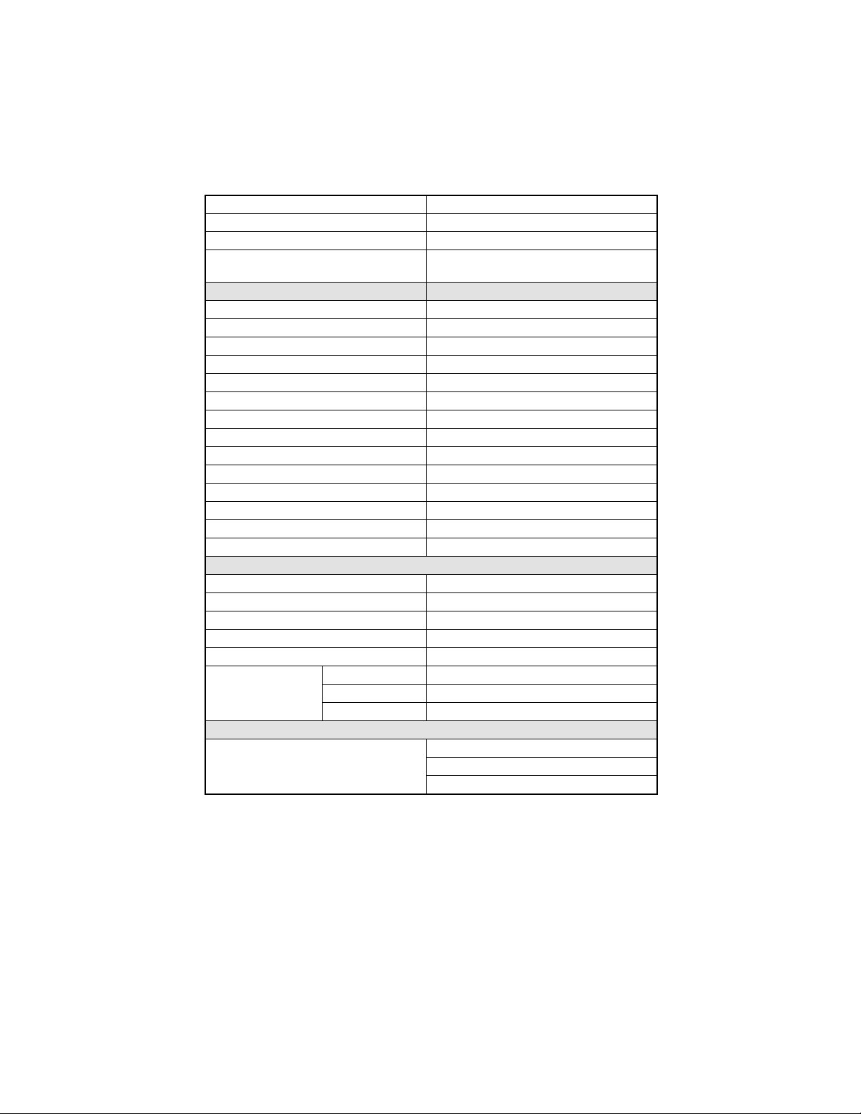
1. Specifications
Item Specifications
General
Protocol (Compatibility) Group3
Multi access Yes
Applicable line PSTN, PABX
Maximu m da t a rat e (bp s) 33.6k bp s, Auto m atic fall back
Coding scheme MH/MR/MMR/JBIG
Dual line No
Intern et fax Option
Error correction mode (ECM) Yes (FAX NIC required)
Standar d memory 4 MB
Option al memory 8 MB
Transmission
Max. Docu ment (Origi nal) size A3
Transmission speed
Broadcasting
3.0 sec.
ITU-T No.1, 33.6k with JBIG (A4-L)
143 Loca tio n per sessio n
Function Location
One to uc h key 27
Speed dial 100
On the fly (Ten ke y) 16
Total 143
Memory TX Yes
Quick me m o r y TX Yes
ADF TX Yes
Manual TX Yes
Timer TX Yes
Polling TX Yes - 30 files
Book TX Yes
Confidential mailbox TX Yes
Sub-address [SUB] capability Yes
Password [PWD] capability Yes
Relay initiate Yes
Relay broadcast Yes
Batch TX Yes
F code function Yes
1
Page 12

Item Specifications
Standa r d: 20 3 × 98 dpi / 8 × 3.85 dpm
TX resolution
Receiving
Max. recording paper size A3
Confidential mailbox RX Yes
Selective polling re ception Yes
Memory RX Yes
Memory RX mode Yes
RX reduction Yes
RX mode Auto/Manual
Printing mode
Footer Yes
RX resolution
Dialing
One-to uc h 27 key
Auto D i al
Auto redial Yes
Last redial Yes
Chain dial Yes
Combination dial Yes
Phone Book Yes
On-ho ok dial Yes
Scanning
Scanner type CCD
Size of document A5 - A3
Max. effective scan width
Maximum numbe r o f st acked orig inals 50 page s
Contra st contr ol Normal/ Dark/Li gh t
Gray scale 256 levels
Recording
Printer type Laser
Speed dial 100
Program mi ng dial 4 key (No.24 - No. 27 )
Group dia l 27
Fine: 203 × 196 dpi / 8 × 7.7 dpm
S-Fin e: 40 6 × 392 dpi / 16 × 15.4 dpm
100%
Bottom cut
Auto re du ction (70% - 10 0% )
Standa r d: 20 3 × 98 dpi / 8 × 3.85 dpm
Fine: 203 × 196 dpi / 8 × 7.7 dpm
S-Fin e: 40 6 × 392 dpi / 16 × 15.4 dpm
4896 pixels per scanning line length of 300 mm ±
1%
2
Page 13
Item Specifications
Printing resolution 600(H) × 600 (V) dpi
Smoothing Yes
Continuous printing sp eed
Report
TX confirmation report Yes
TX error report Yes
RX result report Yes
Activity report Yes
Memory data list Yes
Memory image list Yes
Key setting list Yes
Broadcast result report Yes
Relay broadcast report Yes
Machine status list Yes
Consum a ble or d er report Yes
PCL configuration page (for printer option) Yes
PCL font list (for printer option) Yes
Backup RAM lost report Yes
Other Features
Speaker Yes
Daylight saving time Yes
Ext.phone connector Yes
RTC backup 2.5 years
Multi-c opy 99 pa ge s
No toner Yes
Substitute receiving
PC Function
RS232 Por t func ti on
No paper Yes
Paper jam Yes
15 pp m ( 71 15F)
18 ppm (7118F)
LSD initial set
Class 1 function
TWAIN scanner function
3
Page 14
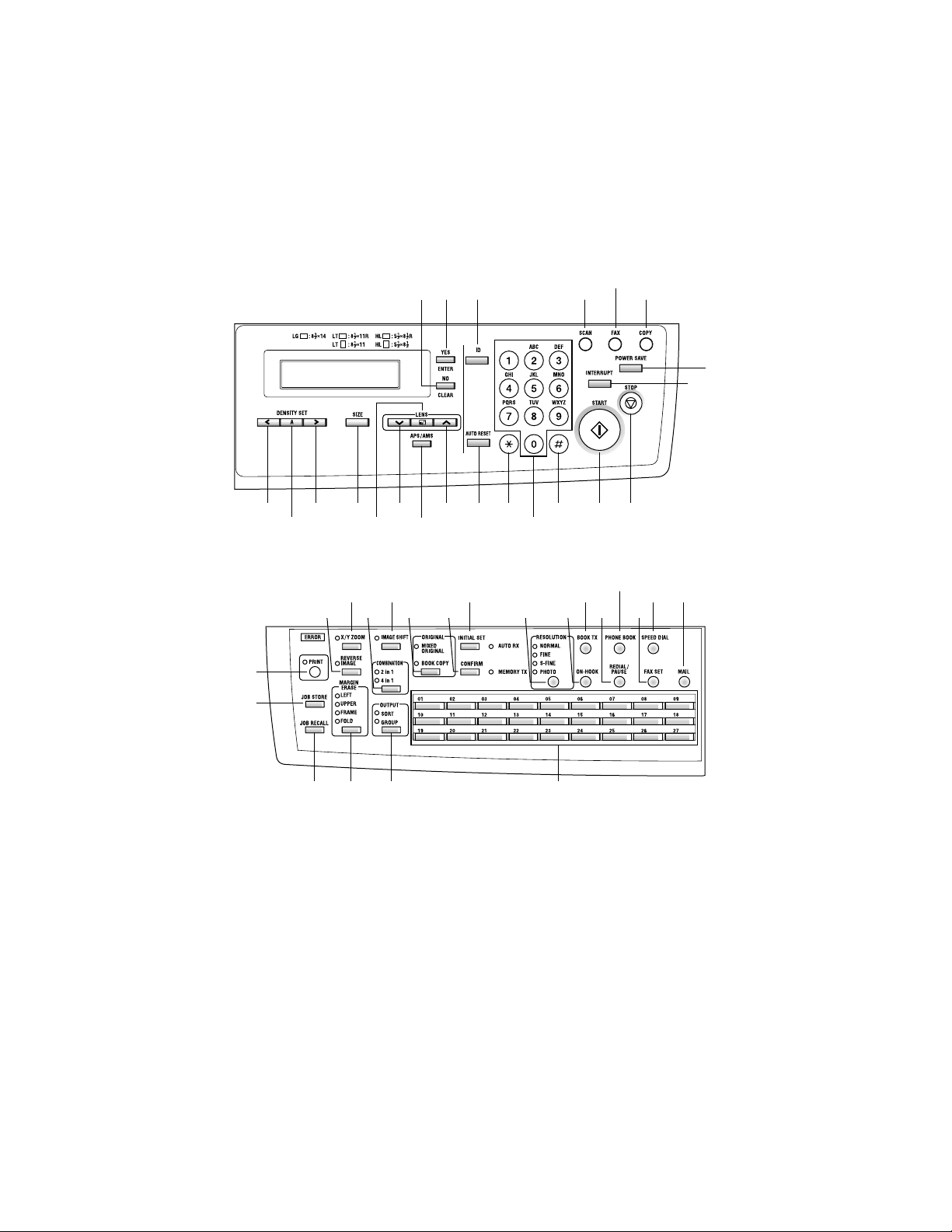
2. Panel Descr ipt ion
Except Europe Area
11
1291314
10
8
7
22
43
42
21 16
37
40 39 23
41
5315171920
18
4
16
2
27
293235
25 24
26283031333438 36
4
Page 15
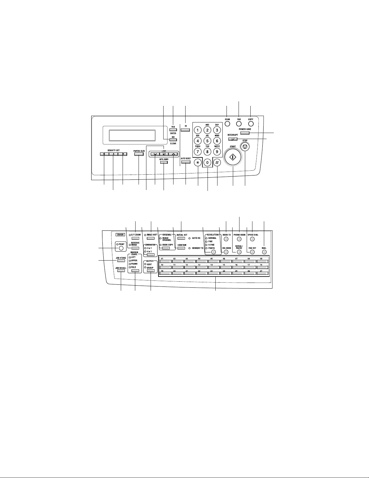
Europe Area
11
1291314
10
8
7
22
43
42
21 16
37
40 39 23
41
18
315171920
4
165
2
27
293235
25 24
26283031333438 36
5
Page 16
Key Function
No. Key Function
1 Start Key
2Stop Key
3Auto Reset Key
4 KEYPAD
5 Tone Key Send tone signal.
6 Extern al Key External / Intern al function.
7 Interrupt Key Sets the copier into, or lets it leave the Interrupt mode.
POWER SAVE
8
Key
9ID Key
10 Co py Key Chan g e pa ne l di splay to Copy mode.
Start s a fax transmis sion .
Starts copying.
Stops the fax transmission or reception.
Stops the multi-page copy operation.
Return to the initial setting
Initial: Copy mode
Number of Copies 1
Zoom ratio: Full size
Copy Func tion: Ini t ia l se tt i ng by us er
Density : Initia l setting by us er
Copy mod e: Initia l se tt i ng by us er
Paper source: I ni ti a l se t ti ng by us er
Initial: Fax m ode
Date, Time, Memory volume, Mes-
Standby:
Under communication
RX in Memory:
RX in Mailbox:
Machine Error : Error message
Substitute RX in Memory: D isplay of memory RX
Number of RX pages: Content of error
Timer TX in Memory Display of standby and T
Polling TX in Memory Display of standby and P
Input fax number.
Input num er a l i n registration of name.
Input speed dial number.
Specify fax function o r initial set item.
Sets the copier into the Energy Saver mode.
If default of Personal id e nti fic a tio n is ON , it chang e s from t he
present section and is made a section number input screen.
sage prompting of the document
loading.
Communication status, Remote Station’s ID, Memory vol um e, Me ss a ge
prompting of the document loading.
Number of RX pages, Memory volume, Message prompting of the document lo ading.
Display of Mailbox RX, Memory volume, Message prompting of the document lo ading.
6
Page 17

No. Key Function
11 Fax Key Change panel display to Fax mode.
12 Scan Key Change panel display to Scan mode.
13 YES / ENTER Key Validate the item and number or character entered.
14 No/Clear Key
15
16
LENS Key, Up and
Down Keys
17
18 APS / APM Key Press to select either Auto Paper or Auto Size.
PAPER SIZE Key
19
(SIZE Key)
20
DENSITY Key, left
21
and right Keys
22
23 One-touch Dial Keys
24 Ma il Key
25 Spe ed Dial Key Call Speed dial.
26 FAX SET Key Call Fax communication function.
TEL BOOK Key
27
(PHONE BOOK Key)
28 Redeal/Pause Key
Clear number or character entered.
Back to the previous display.
Used to select a preset enlargement or reduction ratio.
With each press, a zoom ratio between ×0.50 and ×2.00 in
0.01 increments is selected.
Used to specify the selection above or below in setting
scree ns and m e nus.
Press to select the paper size.
Used to specify the scanning density of copies.
Used to spec if y the s el ec ti on at th e left or r ig ht in setting
screens.
1. One-touch di al 01 - 27
2. Gro up dial 01 - 27
3. Program dial 24 - 27
4. Input @ in registration of name.
5. Input “.” (dot signal) in registration of name.
6. Input “_” in registration of name.
7. Input “+” in registration of dial number.
8. Input “-” (minus signal) in registra t io n of dial number.
9. Input symbols in registration of name.
10. Input Europe an font in r e gistrati on of name.
11.When e nt e ring a n u mbe r or c ha rac t er, delete the char ac ter
or the plac e w ith cursor.
12. When entering a number or character, insert a space in
the place with cursor.
Change the function of One-touch key to either selection of
the registered destina tion or inpu t of cha r ac ter.
Retrieval and call R e gistered dial.
Call the last di aling numbe r.
When entering the dial numb er, ins ert a pause functio n in th e
place wit h cur sor.
7
Page 18

No. Key Function
29 Book TX Key Call book TX function.
30 ON- H O O K Key Press t o ans we r the call. Press again to hang up .
31 Resolution Key Select the resolution and the image mode for transm ission.
32 Initial Set Key
33 Confirm Key
34 Or iginal Key
35 IMAGE SHIFT Key Press to select the File Margin mode.
36 COMBINATION Key Press to select the Copy mode.
37 X/Y Zoom Key
38 REVERSE IMAGE Key
39 OUTPUT Key Press to select the finishing function.
ERASE Key
40
(MARGIN ERASE Key)
41 Job Reca ll Key
42 JOB STORE Key
43 PRINT Key / indicator
Set mac hi ne s ta tus, initia l set tin g for copy, Fax ope rations
and regis ter dials.
Display communication result.
Display machine counter.
Print repor t.
Select the Book Document ( page-by-p age)/Bo ok docum ent
(Spread).
Press t o make a copy with different zoo m ratios set for X
(horizontal) and Y (vertical) directions.
Press to copy an original with the o riginal ton al arrange ments r eversed.
Press to select the erase position.
Press to recall eit her one of the two jobs previously store d in
memory.
Press to select the Job Input mode. Two different jobs can
be programmed.
Lit while data received from personal computer is being
printed.
Blinks while data is being transferred.
For details, refer to the Printer Controller User Manual.
8
Page 19
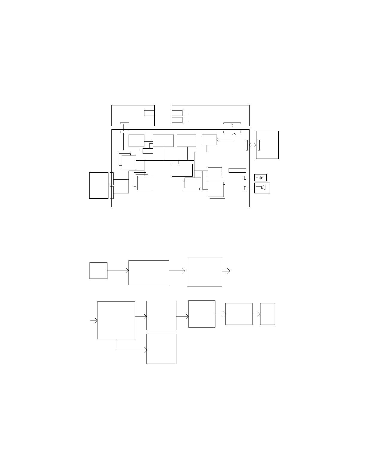
3. FAX CPU BLOCK DIAGRAM
FAX NIC
BOARD
JP5
OPTION
8MB
DRAM
Board
JP4
CN1
CN2
U1 U17 U40
NS32FX
164AV
25
U8/9
SRAM
32KX8
-70
2 Pices
U12/13/52
1. Memory TX Data Flow
CCD
PWB-C SDRAM
4MX16
JBIG FILE
FILE BUFFER
RTC
DRAM
1MX16b
3 Pices
RJ45
ASIC
NS32FX200
-25
U14
TEL
LINE
A/D BUS
DRAM
CONTROL
ASIC
NCU BOARD
CODEC
PM-22C
-33
FLASH
512KX16
-90
U4/61
U12/ U13/ U52
FAX CP U
EDO DRAM
FILE
MEMORY
MODEM
FM336
U27
U23
S-ASIC
EPROM
64KX8
-70
2 Pices
U5/6
CN1
Serial
CN6
CN5
COPIER
BOARD
JP2 JP14
BATTERY
CN3
CN7
SPEAKER
4507M503AC
U40
FAX PM-22C
ENCODE TTI
DECODE JBIG
ENCODE MH
MR...
U12/ U13/ U52
FAX CPU
DRAM
ENCODE
TEMP
BUFFER
FAX CPU
DRAM
DECODE
TEMP
BUFFER
U12/ U13/ U52
DRAM
FRAME
BUFFER
U12/ U13/ U52
9
MODEM
FM336
U23
NCU
4507M504AC
Page 20
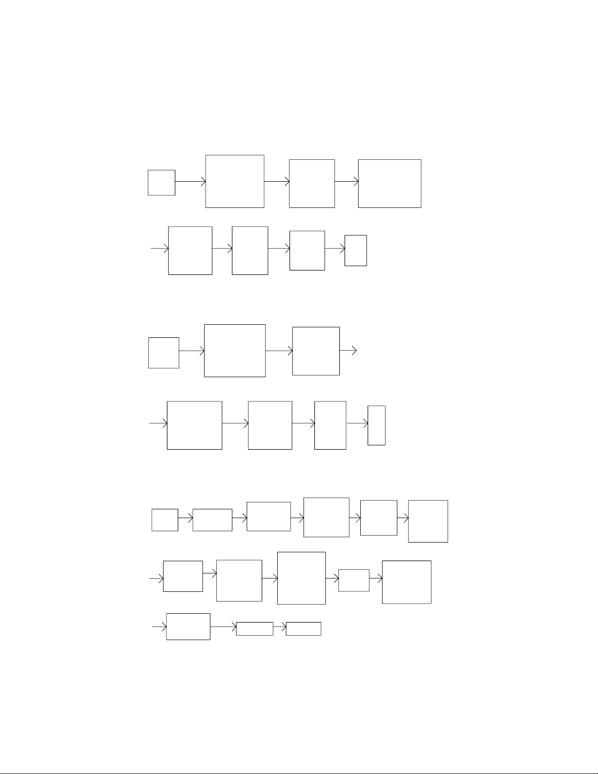
2. Hook TX Data Flow
PWB-C SDRAM
CCD
4MX16
IMAGE DATA
PO BUFFER
U12/ U13/ U52 U12/ U13/ U52
FAX CPU
EDO DRAM
TEMP
BUFFER
DRAM
FRAME
BUFFER
3. TWAIN and C LASS1 Data F low
PWB-C SDRAM
4MX16
CCD
FAX PM- 22C
ENCODE
MH CODE
IMAGE DATA
PO BUFFER
U40 U12/ U13/ U52 U27
FAX CPU
EDO DRAM
TEMP
BUFFER
U12/ U13/ U52
FAX CP U
SCAN
BUFFER
U23
MODEM
FM336
U12/ U13/ U52
FAX CP U
SCAN
BUFFER
S-ASIC
FAX PM-22
ENCODE TTI
ENCODE IMAGE
DATA MH MR...
NCU
PC
U40
4507M505AC
4507M506AC
4. RX (NON ECM, MH or MR) an d Print out Data Flow
U12/ U13/ U52
SOFTWARE
DECODE
IMAGE
DATA
U12/ U13/ U52
FAX CP U
EDO DRAM
PRINT
TEMP
BUFFER
ENGINE
NCU
U12/ U13/ U52
EDO
FILE
MEMORY
IMAGE
ASIC
U23
MODEM
FM336
U40
PM-22
DECODE
IMAGE
DA TA
C-ASIC
U12/ U13/ U52
DRAM
FRAME
BUFFER
10
U12/ U13/ U52
DECODE
TEMP
BUFFER
U17
FX200
PWB-C
SDRAM
FAX PAGE
BUFFER
U40
PM-22
DECODE
IMAGE
DATA
4507M508AC
Page 21
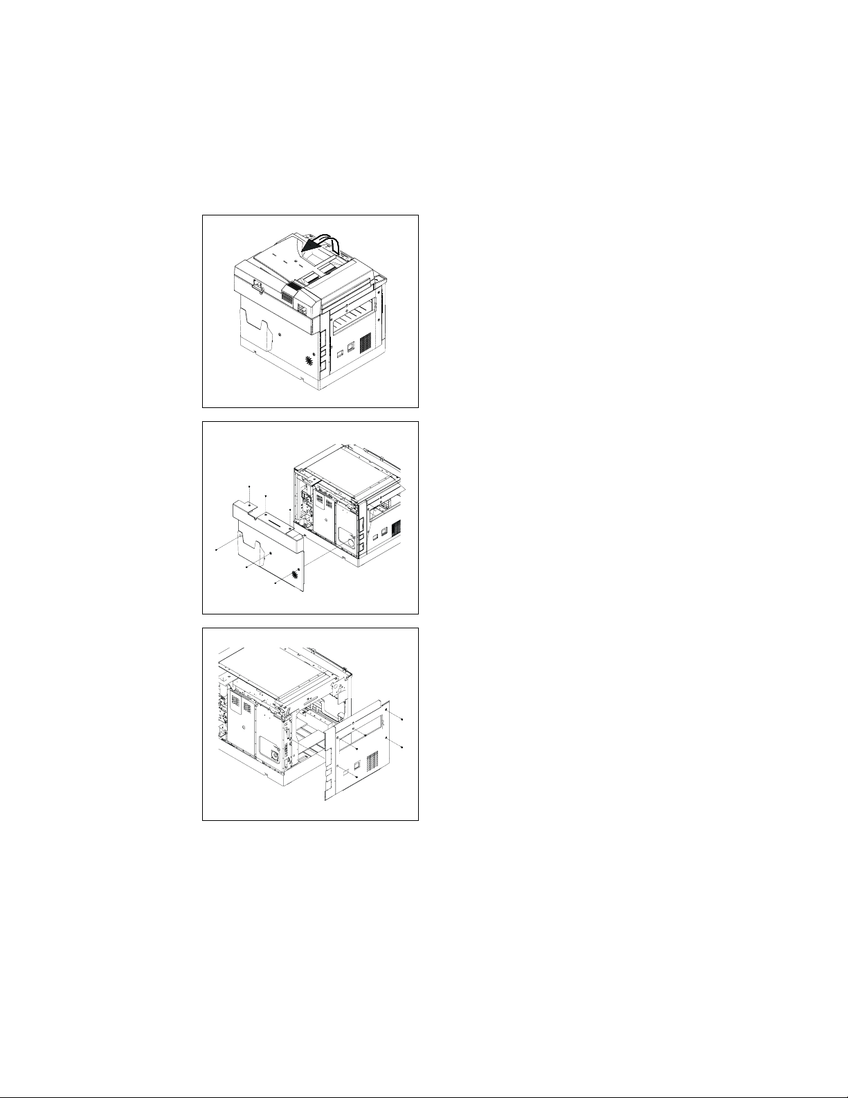
4. ASSEMBLY / DIASSEMBLY
e
4-1. Fax Controller Board Assembly and Disassembly
(1) With Printer Controller Board
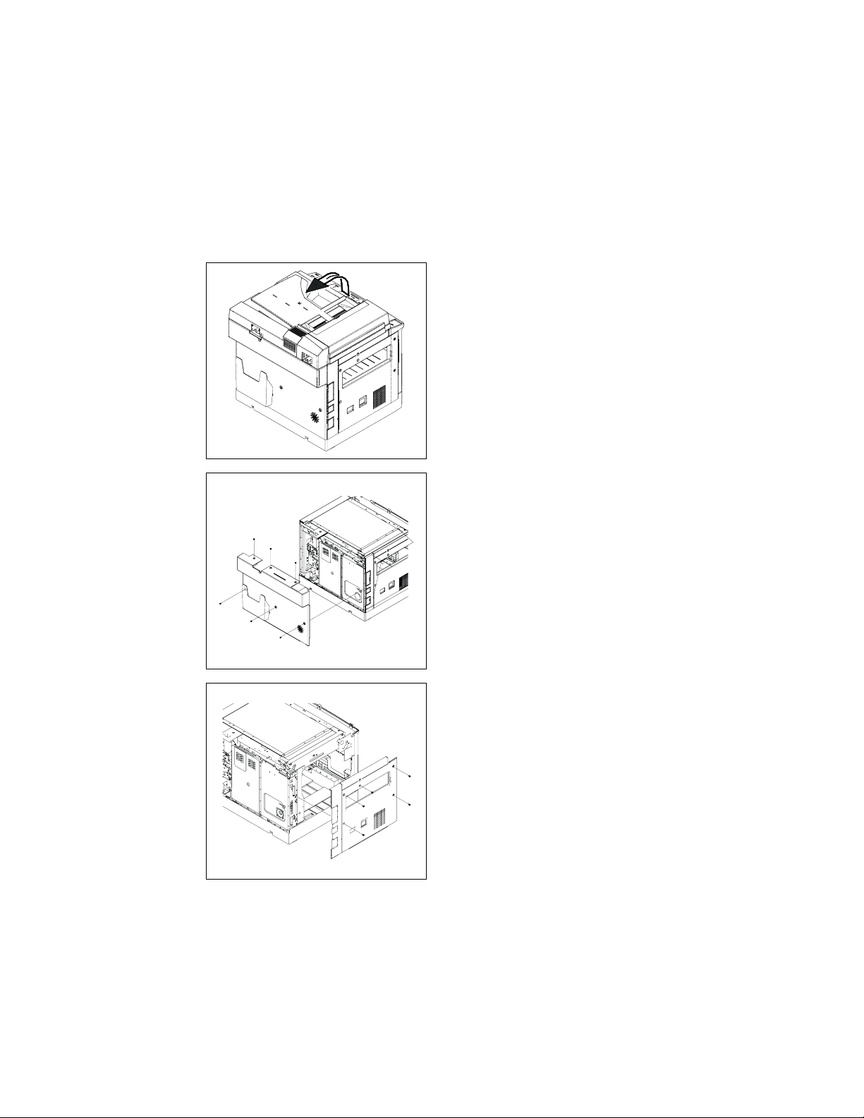
1. Turn off the power switch and remove th
power cord, then rais e the Auto m atic
Document Feeder.
4507D501AA
2. Re move the 6 screw s to r em ove the
Rear Cover and remove the Automatic
Document Feeder.
4507D502AA
4507D503AA
3. Re move the 5 screws to rem ove the Left
Cover.
11
Page 22
4507D504AA
4507D505AA
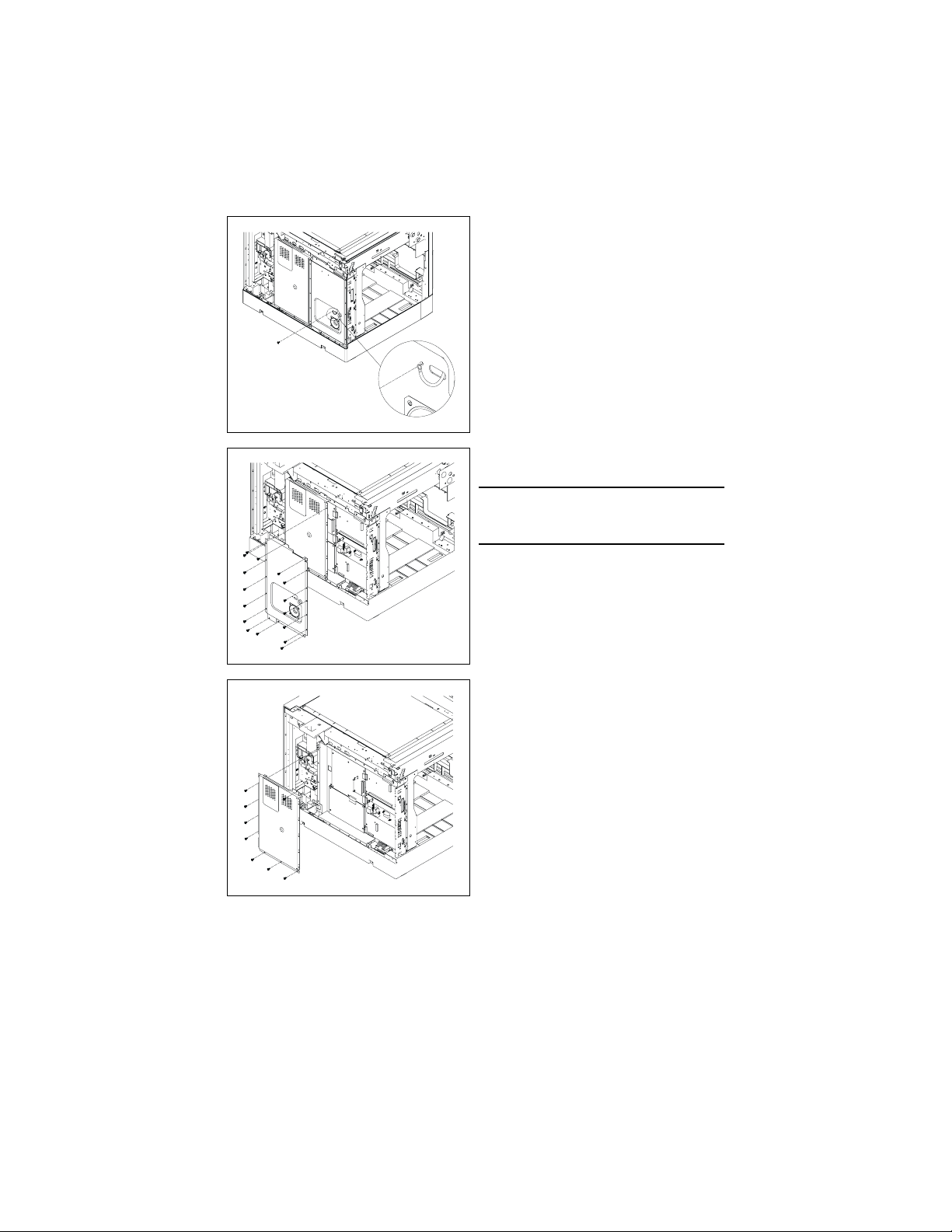
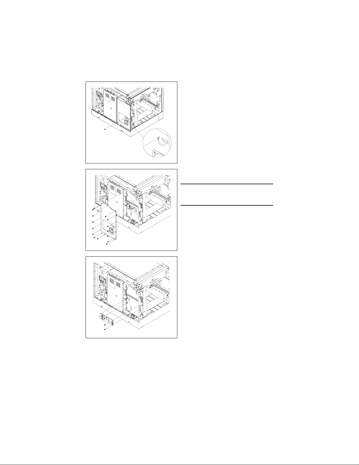
4. Re move the screw for th e gr ound wire of
the NCU Controller Board.
5. Remove the 16 screws to remove the
Fax Shield C over As sembly.
NOTE
• Remove the Speaker Connector before
removing the Fax Shield Cover Assembly.
4507D506AA
6. Re move the 8 screw s to r em ove the
Shield C over Assembly.
12
Page 23
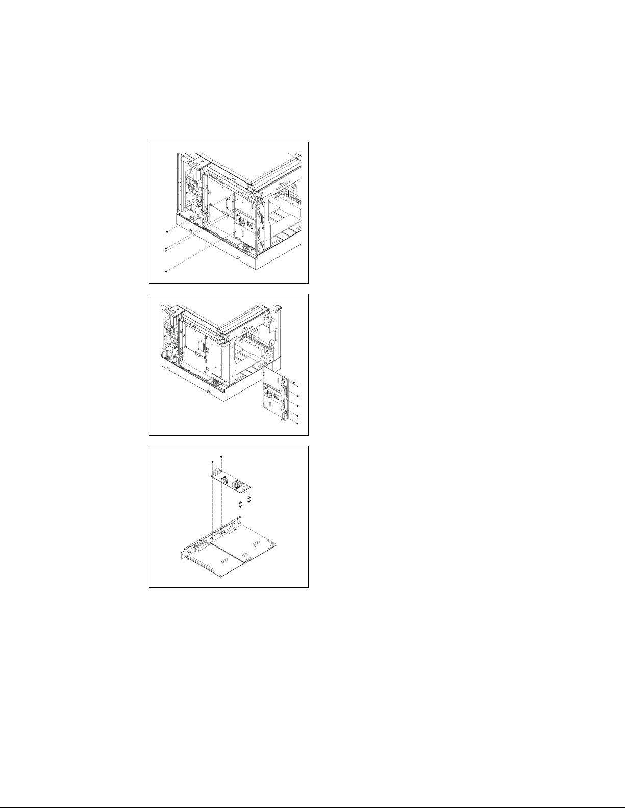
4507D507AA
4507D508AA
7. Re move the 4 screw s for the Printer
Contro ller Board an d the Fax Contr olle
Board.
8. Remove the Battery C o nnector.
9. Re move the 6 screw s to r em ove the I/F
Bracket Assembly.
4507D509AA
10. Remove the 2 sc r ew s an d the 2 PW B
Supports to re move the NCU Controller
Board.
13
Page 24
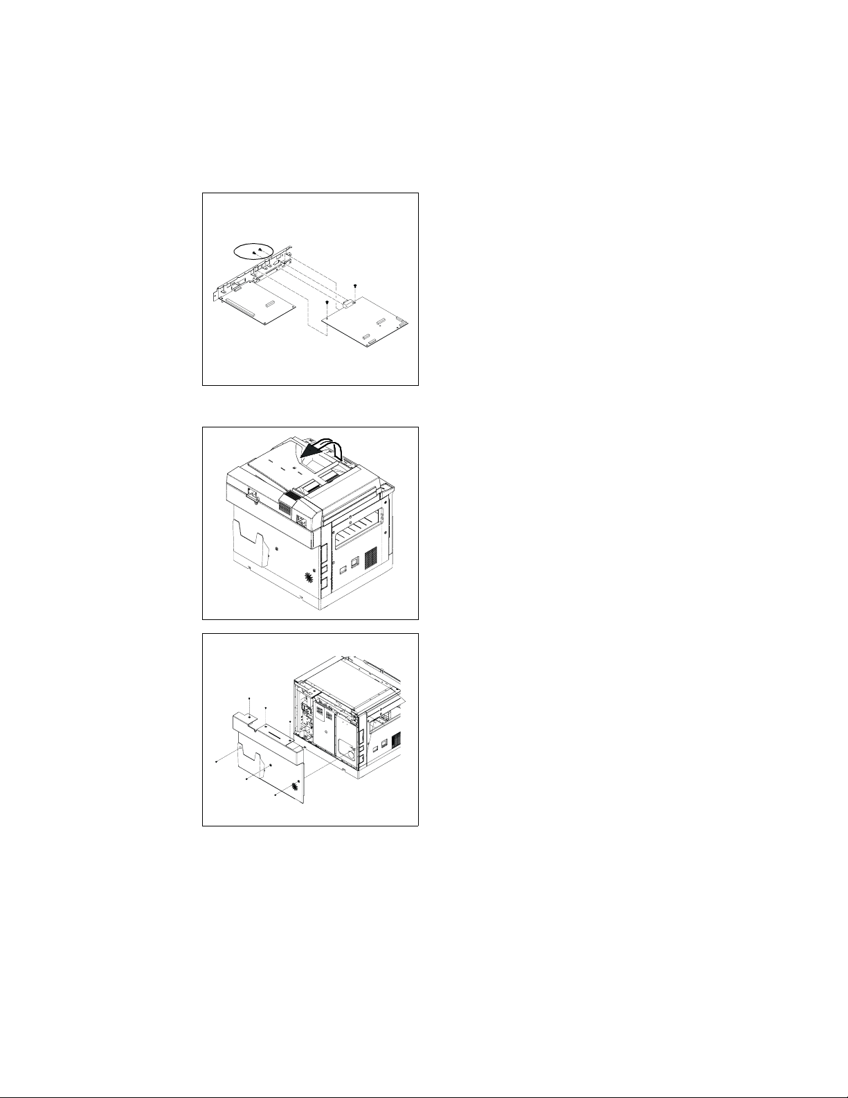
Shoulder Screws
e
4507D507AA
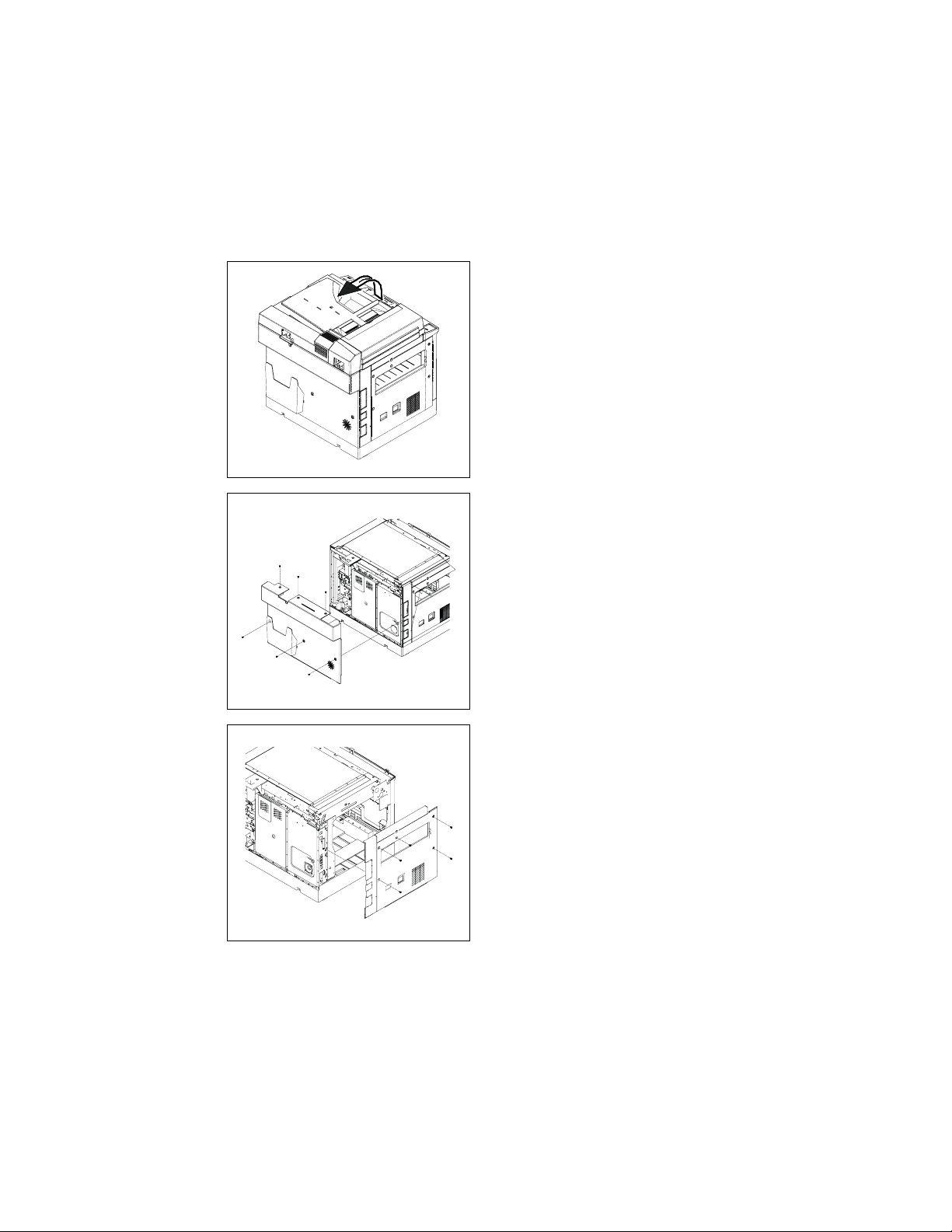
(2) Without Printer Controller Board
11. Remove th e 2 screws, the 2 shoulder
screws to remove the Fax Controller
Board.
1. Turn off the power switch and remove th
power cord, then rais e the Auto m atic
Document Feeder.
4507D501AA
4507D502AA
2. Re move the 6 screw s to r em ove the
Rear Cover.
14
Page 25

4507D503AA
4507D504AA
3. Re move the 5 screws to rem ove the Left
Cover.
4. Re move the screw for th e gr ound wire of
the NCU Controller Board.
4507D505AA
5. Remove the 16 screws to remove the
Fax Shield C over As sembly.
NOTE
• Remove the Speaker Connector before
removing the Fax Shield Cover Assembly.
15
Page 26
4507D506AA
4507D511AA
6. Re move the 8 screw s to r em ove the
Shield C over Assembly.
7. Re move the 2 screw s for the Fax C o n troller Board.
8. Remove the Battery C o nnector
4507D512AA
9. Re move the 6 screw s to r em ove I/ F
Bracket Assembly.
16
Page 27
Shoulder Screws
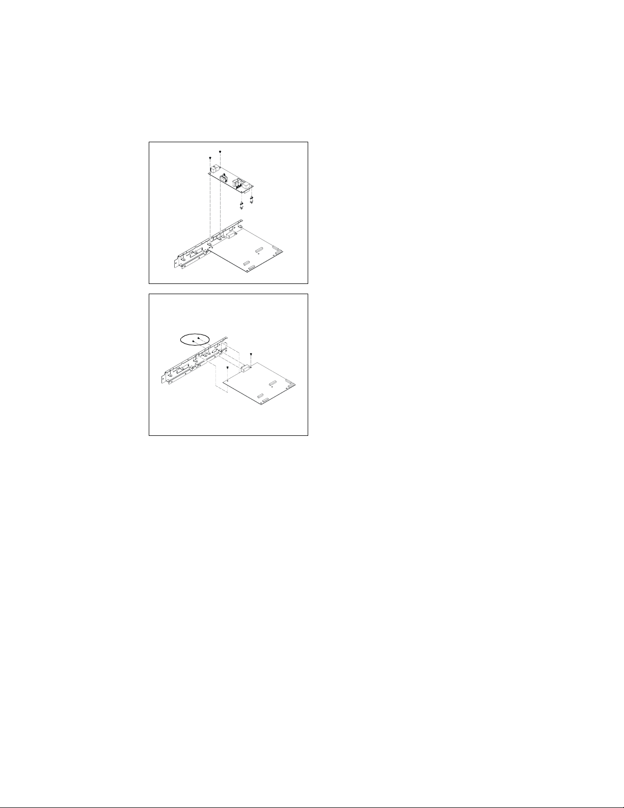
10. Remove the 2 sc r ew s an d 2 PW B Supports to remove the NCU Controller
Board.
4507D513AA
11. Remove th e 2 screws, the 2 shoulder
screws to remove the Fax Controller
Board.
4507D514AA
17
Page 28
4-2. NCU Controller Board Assembly / Disassembly
e
1. Turn off the power switch and remove th
power cord, then rais e the Auto m atic
Document Feeder.
4507D501AA
2. Re move the 6 screw s to r em ove the
Rear Cover.
4507D502AA
4507D503AA
3. Re move the 5 screws to rem ove the Left
Cover.
18
Page 29
4507D504AA
4507D505AA
4. Re move the screw for th e gr ound wire of
the NCU Controller Board.
5. Remove the 16 screws to remove the
Fax Shield C over As sembly.
NOTE
• Remove the Speaker Connector before
removing the Fax Shield Cover Assembly.
4507D515AA
6. Re move the 2 screw s an d the 2 P WB
Supports to re move the NCU Controller
Board from the Fax Controller Board.
19
Page 30
4-3. PWB-C Board Assembly / Disassembly
e
(1) With Fax Controller Board
1. Turn off the power switch and remove th
power cord, then rais e the Auto m atic
Document Feeder.
4507D501AA
2. Re move the 6 screw s to r em ove the
Rear Cover.
4507D502AA
4507D503AA
3. Re move the 5 screws to rem ove the Left
Cover.
20
Page 31

4507D504AA
4507D505AA
4. Re move the screw for th e gr ound wire of
the NCU Controller Board.
5. Remove the 16 screws to remove the
Fax Shield C over As sembly.
NOTE
• Remove the Speaker Connector before
removing the Fax Shield Cover Assembly.
4507D506AA
6. Re move the 8 screw s to r em ove the
Shield C over Assembly.
21
Page 32

4507D511AA
4507D512AA
7. Re move the 2 screw s for the Fax C o n troller Board.
8. Remove the Battery C o nnector.
9. Re move the 6 screw s to r em ove the I/F
Bracket Assembly.
4507D516AA
10. Remove all co nnectors on the PWB-C
Board.
11. Remove the 6 s c rew s to r em ove the
PWB-C Board.
22
Page 33

(2) With Fax and Printer Controller Board
e
4507D501AA
1. Turn off the power switch and remove th
power cord, then rais e the Auto m atic
Document Feeder.
2. Re move the 6 screw s to r em ove the
Rear Cover.
4507D502AA
4507D503AA
3. Re move the 5 screws to rem ove the Left
Cover.
23
Page 34

4507D504AA
4507D505AA
4. Re move the screw for th e gr ound wire of
the NCU Controller Board.
5. Remove the 16 screws to remove the
Fax Shield C over As sembly.
NOTE
• Remove the Speaker Connector before
removing the Fax Shield Cover Assembly.
4507D507AA
6. Re move the 4 screw s for the Fax C o n troller Boar d an d the Printer Co ntro ller
Board.
7. Remove the Battery C o nnector.
24
Page 35

4507D508AA
4507D516AA
8. Re move the 6 screw s to r em ove the I/F
Bracket Assembly.
9. Re move all conn ec to r s on th e P WB-C
Board.
10. Remove the 6 s c rew s to r em ove the
PWB-C Board.
25
Page 36

(3) With Printer Controller Board
e
4507D501AA
1. Turn off the power switch and remove th
power cord, then rais e the Auto m atic
Document Feeder.
2. Re move the 6 screw s to r em ove the
Rear Cover.
4507D502AA
4507D503AA
3. Re move the 5 screws to rem ove the Left
Cover.
26
Page 37

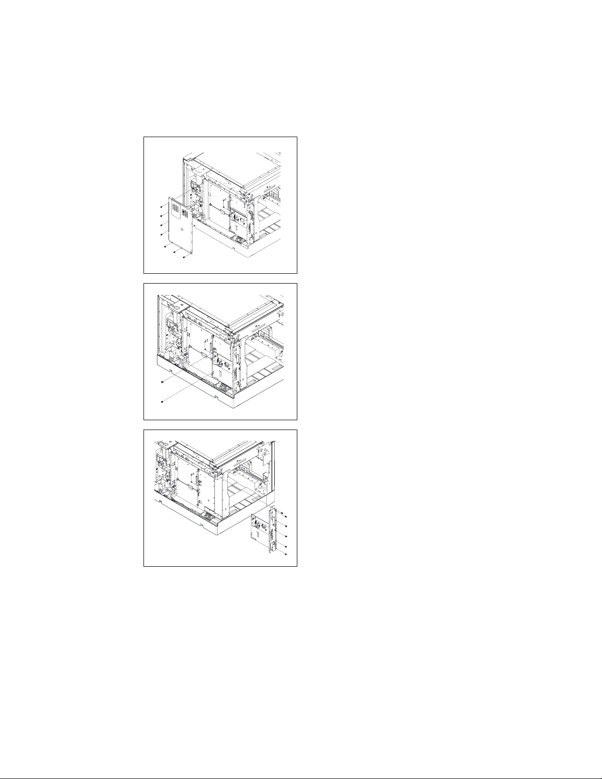
4507D517AA
4507D506AA
4. Remove the 16 screws to remove Fax
Shield C over.
5. Re move the 8 screw s to r em ove the
Shield C over Assembly.
4507D528AA
6. Re move the 2 screw s for the Printer
Controller Board.
27
Page 38

4507D518AA
4507D516AA
7. Re move the 6 screw s to r em ove the I/F
Bracket Assembly.
8. Re move all conn ec to r s on th e P WB-C
Board.
9. Re move the 6 screw s to r em ove the
PWB-C Board.
28
Page 39

4-4. PWB-A Board Assembly / Disassembly
e
(1) With Fax or Prin te r Controller Boar d
1. Turn off the power switch and remove th
power cord, then rais e the Auto m atic
Document Feeder.
4507D501AA
2. Re move the 6 screw s to r em ove the
Rear Cover.
4507D502AA
4507D503AA
3. Re move the 5 screws to rem ove the Left
Cover.
29
Page 40

4507D504AA
4507D505AA
4. Re move the screw for th e gr ound wire of
the NCU Controller Board (With Fax
Controller Board only)
5. Remove the 16 screws to remove the
Fax Shield C over As sembly.
NOTE
• Remove the Speaker Connector before
removing the Fax Shield Cover Assembly.
(With Fax Controller Board only)
4507D506AA
6. Re move the 8 screw s to r em ove the
Shield C over Assembly.
30
Page 41

7. Re move all conn ec to r s on th e P WB-A
e
Board (except for PJ20).
8. Re move the 4 screw s to r em ove the
PWB-A Board.
4507D522AA
4-5. Speaker and Battery Assembly / Disassembly
1. Turn off the power switch and remove th
power cord, then rais e the Auto m atic
Document Feeder.
4507D501AA
4507D502AA
2. Re move the 6 screw s to r em ove the
Rear Cover.
31
Page 42

4507D503AA
4507D504AA
3. Re move the 5 screws to rem ove the Left
Cover.
4. Re move the screw for th e gr ound wire of
the NCU Controller Board.
4507D505AA
5. Remove the 16 screws to remove the
Fax Shield C over As sembly.
NOTE
• Remove the Speaker Connector before
removing the Fax Shield Cover Assembly.
32
Page 43

4507D524AA
4507D525AA
6. Re move the 4 screw s to r em ove the
Speaker.
7. Remove the Battery Connector for the
Battery.
8. Re move the 2 screw s to r em ove the Battery Fix Plat e and the Bat tery.
33
Page 44

4-6. Fax Panel Assembly / Disassembly
• Remove the 4 screws to remove the Fax Controller Panel Assembly
NOTE
• Remove the 2 connectors on the Fax Controller Board.
34
4507D526AA
Page 45

5. ADJUSTMENT
5-1. ADJUST JUMPER SWITCH ON NCU BOARD
• Make the correct settings of the jumper switches at six places on the NCU Board according to the applicable marketing area.
• Wh en the NCU Boar d has been replaced, check that the jumper switches are set as
shown below.
JP1
3 2 1
JP2
1
2
3
Setting --- 1,2 Setting --- 2,3
✽ Country Classification Jumper Switch Setting
Type JP1 ~ JP6 Country
USA, Canada, singapore, Malaysia, Hong Kong,
Russia, Iran, Bahrain, Qatar, Poland, Slovakia,
STD 12,12,12,12,23,23
CTR-21 12,23,23,23,12,12
Australia 12,23,12,12,23,23 Australia, China.
South Africa 23,23,12,12,23,23 South Africa.
China 12,12,12,12,23,12 China
Croatia, Czevh, Slovenia, Baltic, Romania,
Ukraine, Ku wait, P h il ipp in e, Taiwan, UAE, Korea,
New Zealand.
Finland, Iceland, Liec htenstein, Luxe mbourg,
Norway, Sweden, Belgium, Cyprus, Denmark,
F rance, Greece, Ireland, Ita ly, Netherlands,
Swit zerland, Germany, U.K, Portugal, Spain,
Turkey, Hungary, Austria.
3 2 1
JP6
1
2
3
1
2
3
1
2
JP3
3
1
2
3
1
2
3
4507D529AA
JP4
JP5
4507D530AA
35
Page 46

5-2. Upgrading Fax Controller Firmware
(1) Upgrading Procedure Using RS-232C Interface
1. Turn OFF the Power Switch.
2. Connect the Fax Board to the host computer using the RS-232C cable (Straight cable:
terminated in female 9 pin D-Sub connection on both ends).
3. Turn ON the Power Switch.
4. Start the host computer and run “DOS prompt” or “command prompt.”
5. Che ck th e nam e of the se r i al port t o be u sed.
NOTE
• COM1 or COM2 is usually set.
The ports that can be used can be checked with the device manager of Windows.
6. Using the DOS mode command, set the mode for the serial port. If the port used is
COM1, type C:\>mode com1:19,n,8,1 and then press the Enter key.
7. Check that the follo wing message appears, indicating th at the com1 device setting pro-
cedure is completed.
COM1: 19200,n,8,1-
8. Usi ng the C opy comman d, se nd the source file t o t h e Fax Boa r d.
type C:\>copy /b XXX.bin COM1 and then press the En ter key.
36
Page 47

9. The followi ng message appears on the Message Pane l and transfer of firmw ar e data is
started. (Wait until data transfer is completed.)
FIRMWARE DOWNLOAD
Data tra ns fer started
4507D531AC
Approx. 15 min.
FIRMWARE DOWNLOAD
Data transfer completed
4507D532AC
PROGRAM FLASH
4507D534AC
10. The following message appears on the Message Panel, indicating that the firmware has
been properly upgraded.
* PROGRAM COMPLETE *
CHANGE JP5-PJ8
4507D534AC
11. Type “exit” and then press the Enter key.
C:\>exit
12. Make sure that the host computer exits from “DOS prompt” or “command prompt.”
13.Turn OFF and then ON the Power Switch.
37
Page 48

(2) Upgrading Procedu r e Usin g Telephone Line (from fax m ach ine to fax m ach ine)
NOTE
• The firmware transmitter fax machine must be loaded with the latest version of the firmware. If the fi rmware is no t upgra ded, do th at by following th e “Upgrading Procedure
Using RS-232C Interface” described in the previous section.
<Setti ng s ma de on the fa x machine (receiver) to be upgraded>
Select “FULL” for REMOTE MONITOR of the Administrator Mode.
NOTE
• For the REMOTE M ONITOR setting, see “6-9 Administrator number registration.”
1. Press the [INITIAL SET] Key.
2. Press the [Down] Key three times.
ADMN. MANAGEMENT? OK=YES / or 1-3
3. Press the [YES] Key.
ADMN. NO= - - - - - -
4. Enter the Administrator number then press [YES] Key.
NOTE
• Default Administrator number is “000000”.
5. Press the D ow n Key two times, then pr e ss [YES] Key.
3 REMOTE MONITOR? OK=YES
6. Select “Full” using r i gh t/ l eft Key, and press the [YE S ] key.
<Firmw are trans mission procedure (transmitter operat ion)>
1 Set the fir m ware transmitte r fax m ac hi ne in to the Servi ce m od e.
INITIAL SET, Stop, 0, 0, Stop, 0, 1
2. Select “5. FAX SET” or “5. FUNCTION” by pressing the [Up] or [Down] K ey. Then press
[YES] Key.
3. Select “UPLOAD FIRMWARE” by pre ssing the [Up] or [Down] Key. Then press [Yes]
Key.
4. Type the telephone number, to which the firmware receiver fa x machine is connected.
(The relevant one touch dial number may be used if the telephone number has been
previous ly programm ed in it.)
NOTE
• Up to 16 telephone numb ers can be specified sim ult aneously for the firmware r eceiver
fax machi ne.
38
Page 49

5. Press the [Start] key. This starts transfer of the data.
The Mess a ge Panel of the tr an sm itter fax mac hine displays t he same sc re en as tha t
appear in g during ordinary faxing.
When th e da t a tran sf er is completed, the ordinary standby screen reappears on the
Message Panel.
<Operation of receiver after reception of firmware data>
1. Th e firmware rec e iver fax ma ch in e r ec ei ves th e firmware da ta .
The following message appears on the Message Panel, indicating that transfer of firmware data is st a rted.
NOTE
• Do not use an y of the pri nter and copier func tions until upgrading of firmware is completed.
FIRMWARE DOWNLOAD
4507D531AC
FIRMWARE DOWNLOAD
PROGRAM FLASH ROM
“ PLEASE WAIT! ”
Data tran s fer started
Approx. 15 min.
Data transfer completed
4507D532AC
Firmware being uploaded
4507D534AC
2. The following message appears on the Message Panel of the firmware receiver fax
machin e, indicating that upgrading of the firmware is completed.
PROGRAM COMPLETE
POWER SUPPLY OFF/ON
4507D534AC
3. Turn OFF and ON the Power Switch of the firmware receiver fax machine.
39
Page 50

(3) Action T aken When Firm ware Upgrading Fails
• Take the following action when upgradin g of f ir m wa re is not comple te ly p roperly.
CN6
U4
FlashROM
JP5
JP8
JP6
1
1
1
1
2
3
2
2
2
3
3
3
JP7
U61
Flash
ROM
U6
Service
Download
BIOS
U5
Service
Download
BIOS
4507D535AA
Service Download BIOS U5 and U6
(Parts No. : 27BE9701*)
1. Turn OFF the Power Switch.
2. Change the setting for jumper switches JP5 to JP8 on the Fax Board from “2-3” to “1-2.”
1
2
3
2
2
2
3
3
3
JP8JP7JP6JP5
1
2
3
1
1
1
2
2
2
3
3
3
4507D536AA
JP8JP7JP6JP5
1
1
1
3. Mount “Service Download BIOS U5 and U6” on memory sockets U5 and U6 on the Fax
Board.
4. Connect the Fax Board to the host computer using the RS-232C cable (DB-9 connec-
tor).
5. Start the host computer and start “DOS prompt” or “command prompt.”
6. Turn ON the Power Sw itc h. The Me s sa ge Panel will sh ow t he following m es sage.
WAIT PROGRAM
4507D534AC
40
Page 51

(4) Upgrading Procedure Using RS-232C Interface
1. Turn OFF the Power Switch.
2. Connect the Fax Board to the host computer using the RS-232C cable (Straight cable:
terminated in female 9 pin D-Sub connection on both ends).
3. Turn ON the Power Switch.
4. Start the host computer and run “DOS prompt” or “command prompt.”
5. Che ck th e nam e of the se r i al port t o be u sed.
NOTE
• COM1 or COM2 is usually set.
The ports that can be used can be checked with the device manager of Windows.
6. Using the DOS mode command, set the mode for the serial port. If the port used is
COM1, type C:\>mode com1:19,n,8,1 and then press the Enter key.
7. Check that the follo wing message appears, indicating th at the com1 device setting pro-
cedure is completed.
COM1: 19200,n,8,1-
8. Usi ng the C opy comman d, se nd the source file t o t h e Fax Boa r d.
type C:\>copy /b XXX.bin COM1 and then press the En ter key.
41
Page 52

9. The followi ng message appears on the Message Pane l and transfer of firmw ar e data is
started. (Wait until data transfer is completed.)
FIRMWARE DOWNLOAD
Data tra ns fer started
4507D531AC
Approx. 15 min.
FIRMWARE DOWNLOAD
Data transfer completed
4507D532AC
PROGRAM FLASH ROM
* PLEASE WAIT! *
4507D534AC
10. The following message appears on the Message Panel, indicating that the firmware has
been properly upgraded.
PROGRAM COMPLETE
POWER SUPPLY OFF/ON
4507D534AC
11. Type “exit” and then press the Enter key.
C:\>exit
12. Make sure that the host computer exits from “DOS prompt” or “command prompt.”
13.Turn OFF and then ON the Power Switch.
14. Change the setting for jumper switches JP5 to JP8 on the Fax Board from “1-2” to “2-3”
(to retur n to the initial setting ) .
15. Remove “Service Download BIOS U5 and U6” from memory sockets U5 and U6 on the
Fa x Boar d.
16. Turn ON the Power Switch.
42
Page 53

6. Service Mode Function
6-1. Description
(1) HOW TO ENTER INTO SERVICE MODE
• Press the foll ow ing keys in this order to enter the Service mo de:
INITIAL SET, STOP, 0, 0, STOP, 0, 1.
NOTE
• After exiting the Service mode, be sure to turn OFF and ON the Power Switch.
(2) KEY DEFINITION
Key Definition
Left Key Scroll Ba ck war d, M ove C u r s or Left
Right Key Scroll Forward, Move Cursor Right
Up Key Scroll Backward
Down Key Scroll Forward
Start Start Operation
Yes Enter the selected Mode
No/Panel R es e t
Stop
One Touch Key Function Index
Numeric Key Data Entry
Exit and return to next item
43
Page 54

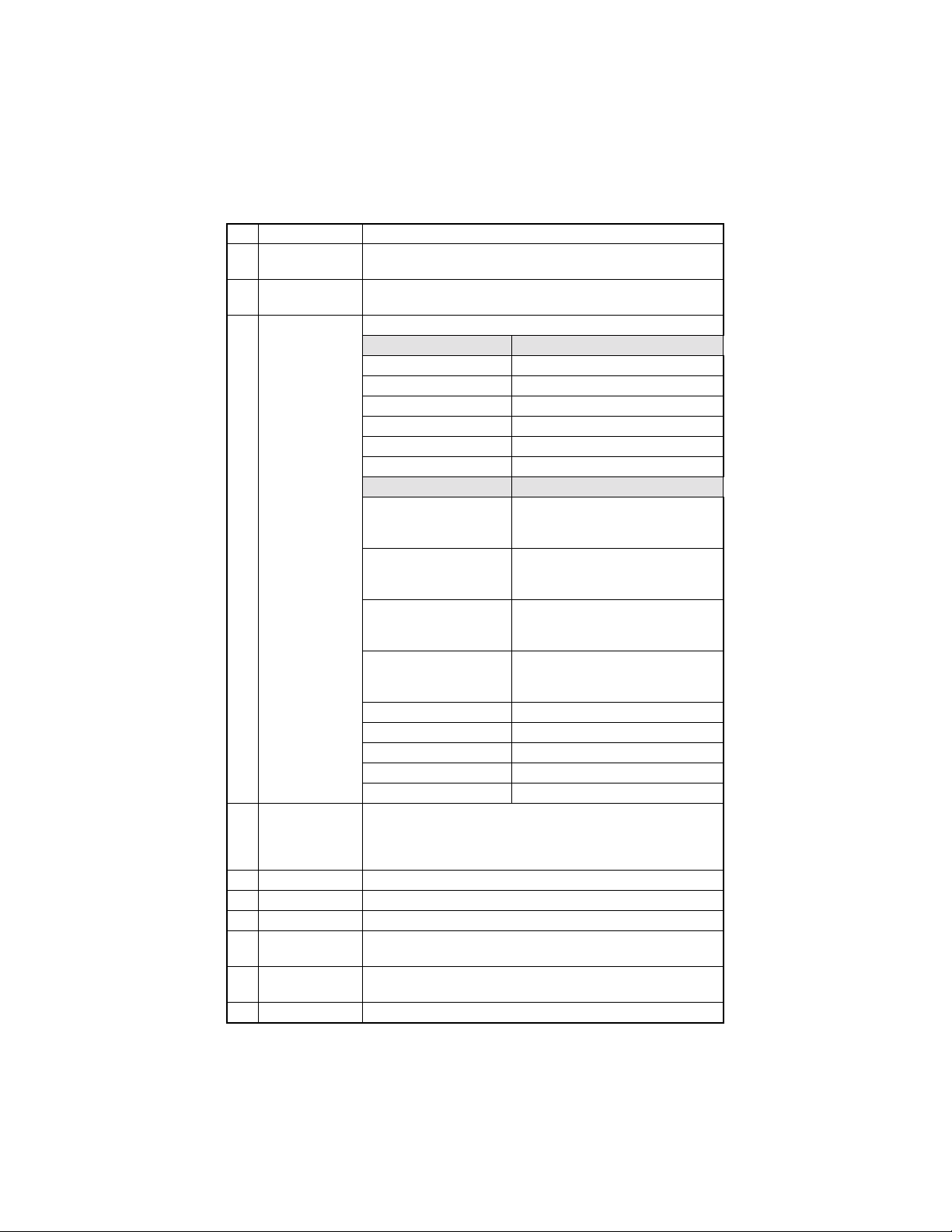
(3) FUNCTION ITEMS
No. Function Items displayed on the LCD panel
1 SERVICE’S CHOICE
2 ADJUST
3 COUNTER
4 DISPLAY
5 FUNCTION
6 SOFT SWITCH
7REPORT
8 ADMIN. REGISTRATION
9 FIXED ZOOM CHANGE
10 FACTORY TEST
11 CLEAR DATA
12 SECURITY
(4) Setting Procedure
1. Cal l the Service mode t o t h e sc re e n.
2. Using the [Up] or [Do wn] key, select th e d e sired function.
3. Press the Yes key to validate the function selected in step 2.
✽ Use the N o key to undo the previou s selectio n of the funct ion.
4. For individual selection of subfunctions, use [Left] or [Right] key, or [Up] or [Down] key.
5. Press the Yes key to validate the selection.
44
Page 55

6-2. SERVICE’S CHOICE
• T h e fol low i ng functi on items are available.
No. Function items displayed on the LCD panel
1 MARK ETING AREA
2 SHIPMENT DESTINATION
3 MAINTENANCE COUNTER
4 IU LIFE STOP MODE
5 ID ADJUST
6 VG ADJUST
7 LEADI N G ED G E ERASE
8 TRAILING EDGE ERASE
9 VERTICAL EDG E ERASE
10 LOOP ADJUST (TRAY 1)
11 LOOP ADJUST (TRAY 2-5)
12 LOOP ADJUST (BYPASS)
13 PRIORITY FLS
14 TX SPEED
15 RX SPEED
16 TX LEVEL
17 RX LEVEL
18 DTMF LEVEL
19 CNG LEVEL
20 CED LEVEL
21 E C M MO DE
22 CODING SCHEME
23 REPORT DESTINATION
24 TONER EMPTY REPORT
25 I U LIFE REPO RT
26 MAINTENANCE REPORT
27 PROTOCOL REPOR T
28 CUSTOMER ID
45
Page 56

(1) MARKET ING AREA
• Set the marketing area.
• I f you change the marke t in g a rea, the sof t swi tc h (1-64) will change a ut omatically.
MARKETING AREA Setting Proce du re
Use the on e t ou ch key, or [Up] or [Down ] key to selec t any nu m be r fro m 1 to 27 .
One Touch Marketing area One Touch Marketing ar ea
1
2 U.S.A. 16 GREECE
3 TAIWAN 17 ISRAEL
4SPAIN18AUSTRIA
5ITALY19GERMANY
6 BELGIUM 20 FRANCE
7 NORWAY 21 UNITED KINGDOM
8 SWEDEN 22 AUSTRALIA
9 NETHERLANDS 23 CHI NA
10 FINLAND 24 NEW ZEALAND
11 DENMARK 25 KOREA
12 SWITZERLAND 26 CZECH
13 IRELAND 27 SLOVAK
14 PORTUGAL
Use the [Up] or [Down] key to sele ct the number.
No. Marketing a rea No. M arketing area
28 HUNGARY 38 HONG KONG
29 UKRAINE 39 PHILIPPINES
30 BALTIC 40 THAILAND
31 WEST EUROPE 41 INDONESIA
32 SLOVENIJA 42 OMAN
33 POLAND 43 UAE
34 ROMANIA 44 QATAR
35 RUSSIA 45 BAHRAIN
36 SINGAPORE 46 KUWAIT
37 MALAYSIA 47 SAUDI ARABIA
STANDARD
(Factor y use only)
15 SOUTH AFRICA
48 JAPAN
46
Page 57

(2) SHIPMENT DESTINATION
• Set the shippi ng destination.
No. Description
1JAPAN
2 INCH
3METRIC
4CHINA
• Default :
Sales Country Default Sales Countr y Default
Europe METRIC Korea METRIC
South Africa/ Australia METRIC China CHINA
Argentina METRIC US A/ Cana da INCH
Philippines METRIC Taiwan METRIC
(3) MAINTENANCE COUNTER
• T h e se t ting range of count value is 0-999999 .
• It is used as guideli ne s fo r the number of copier to be made before th e next mai ntenance
time.
• S e le ct the coun ting method of the main t e na nc e co unter.
Setting Procedure
1. Select the setting value using the [Left] or [Right] key.
2. Press the Yes key.
✽ When 1 or 2 is selected for the setting value, the count value entry screen automatically
appears.
3. Type the count value from the 10-Key Pad.
4. Press the Yes key.
Setting value Meaning Specification Default
0 NO COUNT Nothing ❍
1 PERMITS COPYING Display “M1”
2 INHIBITS COPYING Display “CALL SERVICE (M1)”
• W h en count val ue becomes zero , a minus count is performed. It is countable to -9 99 9 9.
47
Page 58

(4) IU LIFE STOP MODE
• The machine enters the IU Life Stop mode as soon as the count of the IU Life Counter
reaches the life value which is calculated by an internal counter.
• T h e in itial value of t h e IU Life C o un t er is 4 0,000.
• The IU Life Stop mode offers the following setting parameters:
Setting Value Description Default
Copying inhibited
“M2” is displayed w h en the IU Life C o unter reach e s
STOP
CONTINUOUS
• When “Continuous” is selected, the IU Life Counter continues counting down e ven after it
has re ad “0” and counts dow n to -99999 . In this case, h owever, pr int quality is not gu a ranteed.
(5) ID ADJUST
• Adjust the printi ng density. The setting v alues are as f ollows.
Setting Value Default
-3
-2
-1
40,000.
The message “Call Servi ce (M 2)” is displayed and the
print cycl e i s stop pe d wh en the IU Li f e C oun t er r e aches
50,000.
Copying permitted
“M2” is displayed and the print cycle is continued when
the IU Life Counter reaches 40,000.
0 ❍
1
2
3
❍
(6) VG ADJUST
• Vary the Vg voltage to adjust image density.
• The function is used when a fog or a void occurs.
• Increase the setting value to eliminate void.
• Decrease the setting value to eliminate fog.
Setting value De fault
-2
-1
0 ❍
1
2
48
Page 59

(7) LEADING E DGE ERAS E
• E rase the lea ding edge image , the erase width ranging from zero to 5 mm.
Setting value De fault
0 mm
1 mm
2 mm
3 mm
4 mm ❍
5 mm
(8) TRAILING EDGE ERASE
• Erase the trailing edge image, the erase width ranging from zero to 5 mm.
Setting value Default
0 mm
1 mm
2 mm
3 mm
4 mm ❍
5 mm
(9) VERTICAL EDGE ERASE
• E rase the rear and fro nt edges of the image.
Setting Value Default
0 mm
1 mm
2 mm
3 mm
4 mm ❍
5 mm
(10) LOOP ADJUST (TRAY1), (TRAY 2-5), (BYPASS)
• Adjust the length of the loop to be formed in paper before the Synchronizing Roller.
• W h en a skew or misfeed occurs.
• Can adjust for MP, Bypass and Tray 2 to Tray 5, setting value as below. (Unit=mm)
No.
Setting Value
1 2 3 4 5 6 7 8 9 10 11 12 13 14 15
-3.9 -3.3 -2.8 -2.2 -1.7 -1.1 -0.6 0 0.6 1.1 1.7 2.2 2.8 3.3 3.9
49
Page 60

(11) PRIORITY FLS
• Set the size of FLS. (F4 size)
Contents Default
330 x 203
330 x 210 ❍
330 x 216
330 x 220
337 x 206
(12) TX SPEED
• Transmit start speed setting. Choose the mode from among the following. Default is V.34
33600.
Mode Speed Default
V.34 33600, 31200, 28800, 26400, 24000, 21600, 19200, 16800 ❍
V.17 14400, 12000, 9600, 72 00
V.33 14400, 12000
V.29 9600, 7200
V.27 4800, 2400
(13) RX SPEED
• Reception start speed setting. Choose the mode from among the following. Default is
V.34 3360 0.
Mode Speed Default
V.34 33600, 31200, 28800, 26400, 24000, 21600, 19200, 16800 ❍
V.17 14400, 12000, 9600, 72 00
V.33 14400, 12000
V.29 9600, 7200
V.27 4800, 2400
(14) TX LEVEL
• PSK/FSK signal output l evel.
Setting Value Default
-2 dbm
.
.
-9 dbm ❍
.
.
-17 dbm
50
Page 61

(15) RX LEVEL
• Reception sensitivity level.
Setting Value Default
-36 dbm
.
.
-43 dbm ❍
.
.
-49 dbm
(16) DTMF LEVEL
• D u al tone outp ut level.
Setting Value Default
-2 dbm
.
.
-10 dbm ❍
.
.
-17 dbm
(17) CNG LEVEL
• C alling to ne ou t put level.
Setting Value Default
-2 dbm
.
.
-11 dbm ❍
.
.
-17 dbm
51
Page 62

(18) CED LEV EL
• Answer tone output level.
Setting Value Default
-2 dbm
.
.
-11 dbm ❍
.
.
-17 dbm
(19) ECM MODE
• Se lect err or correction mod e.
Setting Value Description Default
ON
OFF Any error is ignored during communication.
(20) CODING SCHEME
• Select compression method in TX/RX mode.
Setting Value Default
JBIG ❍
MMR
MR
MH
When an error occurs during communicati on, re-send
the frame where the error occurs.
❍
52
Page 63

(21) REPORT DESTINATION
• E n t er the telephone numb er for which the r e port is to be p rodu ced.
• Fax number specifications: An up-to-20-digit number that may consist of “0-9”, “ * ”, and
“#”. (0-9, #, *)
• W h en any of the following cond itions happe ns, the report is sent to the destination .
1. Toner-empty condition
(Refer to (22) TONER EMPTY REPORT)
2. The IU Life Counter exceeds the specifications.
(Refer to (23) IU LIFE REPORT)
3. The Mai ntenance C ounter reaches a preset value.
(Refer to (24) MAINTNANCE REPORT)
✽ The re port will be produced at a timing of 20 m i n., 24 hour s , 48 hou rs, a nd 7 2 ho urs aft e r
any of t he above conditions has occurred until the condition disappears.
✽ If two or more conditions occur, only one report will be p roduced.
<Report sample>
SERVICE REPORT
NAME: ABC
TEL: 886-3-4733507
DATE: APR.10.2001 12:20
The FAX’s fo llowing condition appears, the machine may not
work correctly, the Fax already sent a report to your dealer
automatically. They will contact you soon.
Toner status : Empty or Full
Maintenance counter : 125
Supplies life counter : 39938
53
Page 64

(22) TONER EMPTY REPORT
• Select to generate a report to a specific destination when toner empty (Copying inhibited)
status occurs in the engine.
Setting Value Description Default
OFF Not to generate report. ❍
ON Generat e a r e port to report destination.
(23) IU LIFE REPORT
• Select to generate the report when IU LIFE COUNTER becomes out of life, with the condition that the setting value of the counter is set to “STOP”.
Setting Value Description Default
OFF Not to generate a report. ❍
ON Generate a report to destination.
(24) MAINTENANCE REPORT
• Select to ge ne r ate t he repor t when Maintenanc e co un ter beco m es ze ro, with the condition that the setting v alue of th e counter is se t to “2”.
Setting Value Description Default
OFF Not to generate report. ❍
ON To generate a rep ort to repo rt de stination .
(25) PROTOCOL REPORT
• Print communica tion report. Choose one from among the following.
Setting Value Description Default
OFF Disable T.30 commu n ication report. ❍
ON Print T.30 communication report.
ON (ERROR) Print T.30 communication report when an error occurs.
(26) CUSTOMER ID
• Select to the maker name of this machine.
Setting Value Description Default
1KONICA ❍
2Other
54
Page 65

6-3. ADJUST
• Following table lists a ll the adjustm ent items available for the machine.
No. Indication on LCD Description
1 PRN MAIN REGIST Ad1 Adjust print start position in the CD direction for MP Tray.
2 PRN SUB REGIST Ad2 Adjust print start position in the FD direction.
3 CCD MAIN ZOOM Ad3 Adjust horizontal the zoom ratio in the CD direction.
4 CCD SUB ZOOM Ad4 Adjust the zoom ratio in the FD direction.
5 CCD MAIN REGIST Ad5 Adjust scan start position in the FD direction.
6 CCD SUB REGIST Ad6 Adjust scan start position in the CD direction.
7 ADF SUB ZOOM Ad7 Adjust ADF zoom ratio in the FD direction.
8 ADF MAIN REGIST Ad8 Ad jus t ADF start read ing po siti on in the CD dir e cti on.
9 ADF SUB REGIST Ad9 Adjust ADF start reading position in the FD direction.
10 ADTC GAIN Ad10 ATDC sensor Gain Ma nual adjustment .
11 MODEL SETTING Ad11
12 SERIAL NU M BER Ad12
(1) PRN MAIN REGIST Ad1
• Adjust the CD start po sition while pr inting using TRAY1.
• I t is used when the PH Unit ha s been replaced .
• Pre ss S TART key to copy for test.
• Press YES key to adjust setting..
Setting Value Contents Default
60 -4.0 m m
61 -3.9 m m
62 -3.8 m m
.
.
98 -0.2 m m
99 -0.1 m m
100 0 mm ❍
101 +0.1 mm
102 +0.2 mm
.
.
138 +3.8 mm
139 +3.9 mm
140 +4.0 mm
This test is for factory adju st me nt only and s ho ul d NOT
be used.
.
.
.
.
55
Page 66

(2) PRN SUB R EGIST Ad2
• A d ju st the FD start posi tio n w hil e printing us in g T RAY1.
• I t is used when the PH Unit ha s been replaced .
• Pre ss S TART key to copy for test.
• Press YES key to adjust setting.
Setting Value Contents Default
67 -6.14 mm
68 -5.95 mm
69 -5.77 mm
.
.
98 -0.37 mm
99 -0.19 mm
100 0 mm ❍
101 +0.19 mm
102 +0.37 mm
.
.
130 +5.58 mm
131 +5.77 mm
132 +5.95 mm
133 +6.14 mm
(3) CCD MAIN ZOOM Ad3
• Adjust CD zoom ratio during CCD scanning.
• It is used when the PH Unit or CCD Unit has been replaced.
• P ress START key to copy for tes t.
• Press YES key to adjust setting.
Setting Value Contents Default
97 -1.2 %
98 -0.8 %
99 -0.4 %
100 0 ❍
101 +0.4 %
102 +0.8 %
103 +1.2 %
.
.
.
.
56
Page 67

(4) CCD SUB ZOOM Ad 4
• Ad just vertical zoom ratio while CCD scanning.
• It is used when the PH Unit or the Scanner Drive Cables have been replaced, or when
the Scann er has been re m oved.
• P ress START key to copy for tes t.
• Press YES key to adjust setting.
Setting Value Contents Default
97 -1.2 %
98 -0.8 %
99 -0.4 %
100 0 ❍
101 +0.4 %
102 +0.8 %
103 +1.2 %
(5) CCD MAIN REGIST Ad5
• Ad just CD start position while CCD scanning.
• It is used when the PH Unit or CCD Unit has been replaced.
• Pre ss S TART key to copy for test.
• Press YES key to adjust setting.
Setting Value Contents Default
20 -8.0 m m
21 -7.9 m m
22 -7.8 m m
.
.
98 -0.2 m m
99 -0.1 m m
100 0 mm ❍
101 +0.1 mm
102 +0.2 mm
.
.
178 +7.8 mm
179 +7.9 mm
180 +8.0 mm
.
.
.
.
57
Page 68

(6) CCD SUB REGIST Ad6
• Ad just FD start position while CCD scanning.
• It is used when the PH Unit or the Scanner Drive Cables have been replaced, or when
the Scann er has been re m oved.
• Pre ss S TART key to copy for test.
• Press YES key to adjust setting.
Setting Value Contents Default
60 -4.0 m m
61 -3.9 m m
62 -3.8 m m
.
.
98 -0.2 m m
99 -0.1 m m
100 0 mm ❍
101 +0.1 mm
102 +0.2 mm
.
.
138 +3.8 mm
139 +3.9 mm
140 +4.0 mm
(7) ADF SUB ZOOM Ad7
• Adjust FD zoom ratio while ADF scanning.
• It is used when th e machine is set up, the PH Unit or Scann e r Dr iv e Cables have be e n
replaced, or the Scanner has been removed.
• Pre ss S TART key to copy for test.
• Press YES key to adjust setting.
Setting Value Contents Default
87 94.8 %
88 95.2 %
89 95.6 %
.
.
100 100 % ❍
101 100.4 %
102 100.8 %
.
.
111 104.4 %
112 104.8 %
113 105.2 %
.
.
.
.
.
.
.
.
58
Page 69

(8) ADF MAIN REGIST Ad8
• Adjust FD start position while ADF scanning.
• It is used when the machine is set up, or the PH Unit or CCD Unit has been replaced.
• Pre ss S TART key to copy for test.
• Press YES key to adjust setting.
Setting Value Contents Default
20 -8.0 m m
21 -7.9 m m
.
.
99 -0.1 m m
100 0 mm ❍
101 +0.1 mm
.
.
179 +7.9 mm
180 +8.0 mm
(9) ADF SUB REGIST Ad9
• Adjust FD start position while ADF scanning.
• It is used when t he PH Uni t or Scan ne r Drive Cables hav e been re plac ed , o r th e S ca nner
has be en r emoved.
• Pre ss S TART key to copy for test.
• Press YES key to adjust setting.
Setting Value Contents Default
50 -5.0 m m
51 -4.9 m m
52 -4.8 m m
.
.
98 -0.2 m m
99 -0.1 m m
100 0 mm ❍
101 +0.1 mm
102 +0.2 mm
.
.
148 +4.8 mm
149 +4.9 mm
150 +5.0 mm
.
.
.
.
.
.
.
.
59
Page 70

(10) ATDC GAIN Ad10
• Adjust the ATDC Sensor voltage.
• It is used when an IU of ano th er mac hi ne is to be us ed or the T/C cont rol vo lt a ge is to be
changed.
• The value, to which ATDC Sensor Automatic Adjustment has been adjusted, is to be the
setting value.
Setting Value Contents Default
123 5.39V
124 5.43V
125 5.48V
.
.
154 6.75V
155 6.79V ❍
156 6.84V
.
.
184 8.06V
185 8.11V
186 8.15V
(11) Model Setting Ad11
No. Default
1 ❍
2
.
.
.
.
(12) Serial number Ad12
• This test is for factory adjustment only and should NOT be used.
60
Page 71

6-4. COUNTER
• T h e follow ing cou nters can be shown on d isplay.
No. Indication on LCD
1 TOTAL COUNTER
2 SIZE COUNTER
3 PM COUNTER
4 MAINTENANCE COUNTER
5 SUPPLIES LIFE COUNT
6 APPLICATION COUNTER
7 MISFEED COU NTER
8 TROBLE COUNTER
9 PAPER SIZE COUNTER
(1) Total Counter
• Display the count of the Total Counter.
• The count system for the Total Counter is set by 6-13. SECURITY
(2) Size Counter
• Display the count of the Size Counter.
• The count system for the Size Counter is set by 6-13. SECURITY
(3) PM c ou nte r
• C o un t s th e freq uency of us e of eac h of the diffe rent parts of the copier.
• The count should be cleared when the corresponding PM part is replaced. (see 6-
12.CLEAR DATA)
• The element to count is as follows.
No. PM counter Indication on LCD
1 Bypass Tray BYPASS
2MP TRAY 1
3Tray 2 TRAY 2
4Tray 3 TRAY 3
5Tray 4 TRAY 4
6Tray 5 TRAY 5
7ADF ADF
8IR IR
9 Ozone Filter OZONE
10 Paper Dust Remover CLEANING
61
Page 72

(4) Mainte nance counter
• Displays the current count val ue of the Maintenance Counter.
(5) Su ppl ies L ife Counter
• Displays the current count value of the Supplies Life Counter.
(6) Application Counter
• Displays the current count value of the Application Counter.
No. Indication on LCD Description
1 COPY PRINT
2 FAX PRINT
3 REPORT PRINT
4PC PRINT
5TX PAGE
(7) Misfeed Counter
• Count the number of times a misfeed occurs.
• A sheet of paper left in the machine is not counte d.
No. Description Indic ation on LCD
1 Bypass Tray BYPASS
2 MP Tray TRAY 1
3Tray 2 TRAY 2
4Tray 3 TRAY 3
5Tray 4 TRAY 4
6Tray 5 TRAY 5
7 Paper pick-up/transport PICK-UP/TSPT
8 Fuser FUSER
9 Separator SEPARATOR
10 ADF (Take-up) ADF (PICK-UP)
11 ADF (Transport) ADF (TSPT)
12 ADF (Ex it) ADF (EXIT)
• Total number of copies made in copy mode.
• I t counts at the ti me of disc harge of a printed page.
• N u mber of pr in ted pages for Fax RX.
• I t counts at the ti me of disc harge of a printed page.
• Total number of printed pages for reports.
• I t counts at the ti me of disc harge of a printed page
for report.
• Total number of printed pages produced from PCL6.
• I t counts at the ti me of disc harge of a printed page.
• Tot al number of Fax TX pages.
• Transmitting number of sheets counts at the time of
the completi on of tran smit t in g.
62
Page 73

(8) Trouble count er
• Count the number of times a Trouble occurs.
No. Counter nam e Indication on LCD
1 Main motor error. [C0000]
2 Fuser fan error. [C0045]
3 Power fan error. [C004E]
4 Toner bottle motor error. [C0070]
5 Transfer voltage error. [C0210]
6 Warm up error. [C0500]
7 Low Temp. error. [C0510]
8 High Temp. error. [C0520]
9 Home sensor error. [C0650]
10 Separator motor error. [C0B60]
11 Shift motor error. [C0B80]
12 ATDC sensor abnormal. [C0F32]
13 ATDC adjustment abnormal. [C0F33]
14 ASIC/ Memory error. [C1200]
15 Polygon mirror motor error. [C1300]
16 HSYNC Detect error. [C13F0]
17 EE PROM Error. [C1468]
18 IR Lamp malfunction. [C14A3]
19 Communi c ation wit h option error . [C133B]
20 Modem error. [C133C]
21 ROM checksum error. [C133D]
• Service call troubleshooting
Service cal l Detection Timing Action
It is not possible to c ommu ni c ate w i th the Printer
[C133B]
[C133C]
[C133D]
✽ Refer to the S ervice Han db ook of the co pie r for t he troubles other than the above -m en -
tioned.
Board with in a predetermined period of time during a print cycle.
An error is de tec t e d of the mode m chip on the
Fax Board when the Power Switch is turned ON.
An error is detect ed of the fl ash ROM chip on the
Fax Board when the Power Switch is turned ON.
Change the Printer
Board or the Control
Board.
Change the Fax Board.
Change the Fax Board.
63
Page 74

(9) Paper Size Counter
• C o un t s th e num be r of she ets of paper use d ac co rding to the s ize an d ty pe.
No. Paper Size Indication
1A3L A3L
2B4L B4L
3A4L A4L
4A4C A4C
5B5L B5L
6B5C B5C
7A5L A5L
8A5C A5C
9 FLSL FLSL
10 11 × 17L 11 × 17L
11 11 × 14L 11 × 14L
12 Leg al L LEGAL L
13 Letter L LETTER L
14 Letter C LETTER C
15 Invoice L INVOICE L
16 Invoice C INVOICE C
17 Other OTHER
18 APS PAPER APS PAPER
19 NOT APS PAPER NOT APS PAPER
20 FI XED PAPER FIXED PAPER
21 OHP OHP
22 THICK PAPER THICK PAPER
64
Page 75

6-5. Display
No. Indication on LCD Description
1 TONER DE NSITY LEVEL Display th e ATDC sensor output (T/C ratio).
2 PROCESS CONTROL Show Vg and Vb value from engine.
3 FAX ROM VER. Display the FAX ROM version.
4 FAX RAM SI ZE Di sp lay t h e FAX Total m emory size.
5 COPIER RAM SIZE 16 or 32 MB for Copier memory.
• Version Information string for FNIC (I-FAX).
6 FNIC VER.
7 PCL PRINTER VERSION
8 PCL PRINTER RAM SIZE
9 SER I A L N O. M ai n bod y Show mach in e se r i al number.
10 PNIC (Printer NIC) VER.
11 ENGINE F/W VER. Show Engine ROM Ver.
• If the optional FNIC kit is not mounted, this
item is not availabl e.
• Version Information string for P/C.
• If the optional print e r kit is not mounted,
“NOT AVAILABLE” is displayed.
• Memory size for PCL printer.
• If the optional print e r kit is not mounted, this
item is not availabl e.
• Show “NOT AVAILABLE” if no PNIC kit.
• If no PNIC is installed, “NOT AV AILABLE” is
displayed.
65
Page 76

6-6. FAX SET
No. Indication on LCD Description
1 PAPER FEED TEST Printing paper feedin g test from selected Tray.
Select output of HV.
2 PROCESS CHECK
3 ATDC SENSOR ADJUST Automatic adjustment of ATDC sensor.
4 PRINT TEST PATTERN Printing a pre-determined test pattern.
5 ADF FEED TEST ADF feeding test.
6 COPY ADF GLASS AREA Copy ADF glass area image.
7 CCD MOVE TO HOME Moving Scanner to home position.
8 UPLOAD FIRMWARE Uploading firmware to remote side machine.
9 FAX RES. COPY TEST Fax resolution copy test.
(1) PAPER FEED TEST
• Correct paper passage (paper transport path) is checked without involving any printing
action.
• Select the paper source.
• Paper passage operation is checked.
• Scanning is not carried out.
• Perform a paper transport check until the paper tray is empty.
• Start by the start key and stop with a stop key.
• It cannot be operated at the time of warming up.
• It cannot operate when paper is set on the Single Bypass Tray.
• The counter does not count during test.(Total-counter etc. )
This test is for facto ry adjustm e nt on ly a nd s ho ul d
NO T be used.
(2) PROCESS CHECK
• This test is for factory adjustment only and should NOT be used.
66
Page 77

(3) ATDC SENSOR ADJUST
• Automatic adjustment of ATDC sensor is performed.
• This test is used when the copier is set up, developer is changed, and the IU is replaced.
• A djus tmen t is star t ed wi th the YES key.
• S top automa ti cally after adjust ment. It is possible t o stop with the “Stop” key in the
midd le of the adjustm e nt sequ ence.
(4) PRINT TEST PATTERN
• Prints the tes t pattern.
• S elect the tray to be used.
• Select the pattern (either pattern 1 or pattern 2).
pattern 1
• This functi on is u sed to iden ti fy the specific func tional unit, either the engine or the IR,
which is responsible for an image problem that has occurred.
• The following are the specific operations.
• Scanning is not carried out.
• It cannot operate at th e time of warming up.
• Start with the “Start” key and stop with the “Stop” key.
• It cannot be operated if paper is set on a Single Bypass Tray.
• A pr in t i ng paper source can be selec ted w ith “Paper” key, except Bypass tray
[single /m ulti]. In the case of FAX model, sele c t the print ing paper source on the
screen of the function mode.
• The counters do not count. (Total-counter etc.)
(5) ADF FEED TEST
• Paper passage operation of ADF is checked.
• Scanning is not carried out.
• Perfor m s an ADF document pass age test un t i l all of the set docume nt ar e fe d.
• The test does not start if document is not loaded.
• S tart with the start key and stop wit h s to p key.
pattern 2
67
Page 78

(6) COPY ADF GLASS AREA
• Check to see if the glass within the scan area is scratchy or dirty.
<Operation>
1. Place a gray chart (O.D.=0.3) on the glass.
2. The Scanner moves from the standby position to a point 2 mm to left of the ADF scan-
ning po sit ion.
3. Th e S ca nner starts rea ding the gr ay chart as i t moves to th e r ight.
4. The machine produces two prints (to distinguish dirt on the glass from printer image
noise).
(7) CCD MOVE TO HOME
• This function is used for securing the Scanner in position for shipment.
• The Scanner moves from the standby position to the left.
• Use the Start key to move the Scanner to the left and the Stop key to return it back to the
standby position .
(8) UPL OAD FIRMWARE
• Download firmware from this machine to remote side, after setup of remote side location.
• Machine w i ll dial automa t ic ally and c opy the EPROM d a ta to remote side ma chine.
• For details, refer to ADJUSTMENT.
(9) FAX RES. COPY TEST
• Se lect CCD FAX or ADF FAX.
• T h e page to be transmitte d is automaticall y p r in t ed.
• T h e da ta w il l not be transm itt e d to the machine on the other en d.
68
Page 79

6-7. SOFT SWITCH
• Refer to the chapter of soft switch for the explanation of soft switch.
SERVICE MODE
6.SOFT SWITCH
• KEY DEFINITION FOR SOFTSWITCH
Key Definition
↓ Soft Switch Number Forward.
↑ Soft Switch Number Backward.
YES Update Soft Switch by current setting.
NO/STOP Exit Soft Sw itc h sett ing
• 1-27 of the soft switch numbers uses and selects an one-
ONE TOUCH
touch key.
• 28-64 of the soft switch numbers uses and selects ↓ key.
YES
SOFT SWITCH
#01=00000000
69
Page 80

6-8. REPORTING
• T h e follow i ng li st is selected, and press YES key.
• After press the Auto Res et key, the list is autom ati ca ll y pr inted.
No. Indication on LCD
1 SERVICE DATA LIST
2 ERROR CODE LIST
3 T.30 PROTOCOL LIST
(1) SERVICE DATA LIST
• Print service data list report and Error log history list.
• After press the Auto Res et key, the list is autom ati ca ll y pr inted.
• S e rvice D a t a list includes t he following i t em s :
1. Report title
2. Soft switch list
3. Communication history and counter
4. Mailbox ID & Password
5. Relay BOX ID and Password
6. RX in memory password
7. Admin. password
8. Section number password
9. ROM ID
• E rr o r l og hi s tory list inc lu de s the following ite m s:
No. Item Description
1 In dex I ndex number from 0 - 9999
2 Error Error code number
3 Maker NSF fram e ma ker code
4 Tele. Remote side or TX side telephone number for that transaction
70
Page 81

1. SERVICE DATA LIST)
NAME:DALLAS
TEL :1234567
DATE:JUL.02’1998 11:55
MARKETIN G AREA=STANDARD
-- SOFT SWITCH -SW01-SW16 00 20 81 0C 00 00 07 61 00 81 10 80 10 00 01 03
SW17-SW32 00 00 68 00 80 06 00 00 00 28 00 A7 14 68 00 00
SW33-SW48 C0 02 10 8A 00 C1 01 08 04 80 80 04 00 02 00 89
SW49-SW64 01 00 01 88 30 B0 F8 15 08 00 08 24 0F 00 80 07
--COMMUNICATION HISTORY & COUNTER -000000: ECM RX TIME 000000: ECM TX TIME
000001: G3 RX TIME 000000: G3 RX PAGE
000000: V.17 14.4K 000000: V.17 12K
000000: V.33 14.4K 000000: V.33 12K
000000: V.17 9.6K 000000: V.17 7.2K
000000: V.29 9.6K 000000: V.29 7.2K
000000: V.27 4.8K 000001: V.27 2.4K
000000: G3 TX TIME 000000: G3 TX PAGE
000000: V.17 14.4K 000000: V.17 12K
000000: V.33 14.4K 000000: V.33 12K
000000: V.17 9.6K 000000: V.17 7.2K
000000: V.29 9.6K 000000: V.29 7.2K
000000: V.27 4.8K 000000: V.27 2.4K
000007: V.34 RX TIME 000007: V.34 RX PAGE
000002: 33.6K 000005: 31.2K
000000: 28.8K 000000: 26.4K
000000: 24.0K 000000: 21.6K
000000: 19.2K 000000: 16.8K
000000: 9.6K 000000: 7.2K
000000: 4.8K 000000: 2.4K
000001: V.34 TX TIME 000015: V.34 TX PAGE
000001: 33.6K 000006: 31.2K
000000: 28.8K 000000: 26.4K
000000: 24.0K 000000: 21.6K
000000: 19.2K 000000: 16.8K
000000: 9.6K 000000: 7.2K
000000: 4.8K 000000: 2.4K
000007: JBIG TX TIME 000007: JBIG RX TIME
000000: TOTAL COUNTER 000000: SIZE COUNTER
000000: MAINTENANCE COUNTER 000000: SUPPLIES COUNTER
000000: COPY PRINT 000000: FAX PRINT
000000: REPORT PRINT 000000: PC PRINT
-- MAILBOX ID & PW -NO.0 ID= PW= NO.1 ID= PW= NO.2 ID= PW=
NO.3 ID= PW= NO.4 ID= PW= NO.5 ID= PW=
NO.6 ID= PW= NO.7 ID= PW= NO.8 ID= PW=
NO.9 ID= PW=
-- RELAY BOX ID & PW -NO.0 ID= PW= NO.1 ID= PW= NO.2 ID= PW=
NO.3 D= PW= NO.4 ID= PW=
-- SECTION PASSWORD -NO.1 : NO.2 : NO.3 : NO.4 : NO.5 :
NO.6 : NO.7 : NO.8 : NO.9 : NO.10:
NO.11 : NO.12 : NO.13 : NO.14 : NO.15:
NO.16 : NO.17 : NO.18 : NO.19 : NO.20:
RX IN MEMORY:
ADMIN.PASSWORD:
-ROM ID 06/14/2000 V0.25-3
SERVICE DATA LIST
71
Page 82

2. ERROR LOG HISTORY LIST
The follow in g tabl e is th e er ro r log hi story. The table keep s th e las t 40 re cords onl y.
ERROR LOG HISTORY LIST
Index Error Maker Tele
0001 : 0070 49EE 88634733507
0002 : 00A0 49EE
0003 : 0070 0000
0004 : 0070 0000
0005 : 0070 0000
0006 : 0070 0000
0007 : 0070 0000
0008 : 0070 0000
0009 : 0070 0000
0010 : 0070 0000
0011 : 0070 0000
0012 : 0070 0000
0013 : 0070 0000
0014 : 0070 0000
0015 : 0070 0000
0016 : 0070 0000
0017 : 0070 0000
0018 : 0070 0000
0019 : 0020 49EE 123
0020 : 0070 0000
NSF signal 3rd. and 4th byte Keep 20 digits of TSI or CSI
72
Page 83

(2) ERROR CODE LIST
• P r int out erro r code as follow in g tabl e.
ERROR CODE TABLE
CODE ERROR TIMES CODE ERROR TIMES CODE ERROR TIMES
0001 00000000 0002 00000000 0003 00000000
0004 00000000 0005 00000000 0006 00000000
0007 00000000 0008 00000000 0009 00000000
000A 00000000 000B 00000000 000C 00000000
000D 00000000 000E 00000000 000F 00000000
0010 00000000 0011 00000000 0012 00000000
0013 00000000 0014 00000000 0015 00000000
0016 00000000 0017 00000000 0018 00000000
0019 00000000 001A 00000000 001B 00000000
001C 00000000 001D 00000000 001E 00000000
001F 00000000 0020 00000000 0021 00000000
0022 00000000 0023 00000000 0024 00000000
0025 00000000 0026 00000000 0027 00000000
0028 00000000 0029 00000000 002A 00000000
002B 00000000 002C 00000000 002D 00000000
002E 00000000 002F 00000000 0030 00000000
0031 00000000 0032 00000000 0033 00000000
0034 00000000 0035 00000000 0036 00000000
0037 00000000 0038 00000000 0039 00000000
003A 00000000 003B 00000000 003C 00000000
003D 00000000 003E 00000000 003F 00000000
0040 00000000 0041 00000000 0042 00000000
00000000 00000000 00000000
00000000 00000000 00000000
00000000 00000000 00000000
00000000 00000000 00000000
00000000 00000000 00000000
00F7 00000000 00F8 00000000 00F9 00000000
00FA 00000000 00FB 00000000 00FC 00000000
00FD 00000000 00FE 00000000 00FF 00000000
73
Page 84

(3) T.30 PROTOCOL LIST
• Print out T.30 or V8 protocol after communication.
1. SESSION NUMBE R
2. FUNCTION NAME
3. DESTINATION NAME/TELEPHONE NUMBER
4. COMMUNICATION DATE & TIME
5. TOTAL PAGE NUMBER FOR THIS SESSION
6. COMMUNICATI ON DURATION
7. COMMUNICATION SPEED AND ECM MO DE
8. COMMUNICATION RESULT
9. T.30 COMMAND SENT BY LOCAL FAX
10. T.30 COMMAND RECEIVED FROM REMOTE FAX
11. T.30 FRAME THAT INCLUDE ADDRESS & CONTROL & DATA
74
Page 85

1. V.17 COMMUNICATION
0
PROTOCOL MONITOR REPORT
NAME: ABC
TEL:886 3 473350 7
DATE: APR.10’97 12:2 0
SESSION FUNCTION NO DESTINA T ION STATION DATE TIME PAGE MODE RESULT
0001 TX 01
ABC
22345678901234567890
ECM-
12
OK
TX RX DATA
NS F FF 03 20 00 00 00 00 00 00 00 00 00 00 00 00 00 00 00 00 00 00 00 00 00
CS I FF 03 40 00 00 00 00 00 00 00 00 00 00 00 00 00 00 00 00 00 00 00 00 00
DIS F F 13 00 00 00 00 00
NS S F F 03 00 00 00 00 00 00 00 00 00 00 00
DCS FF 13 00 00 00 00 00 00 00 00 00
TC F 00 00 00 00 00 00 00 00 00 00 00
CF R FF 13 84
PIX
EO P FF 13 B F 2F 00 00 41
M CF FF 13 8C
DCN FF 13 FB
TRAINING
PHASE
DATA PHASE
75
Page 86

2. V.34 COMMUNICATION
PROTOCOL MONITOR REPORT
NAME: ABC
TEL:886 3 473350 7
DATE: APR.10’97 12:2 0
SESSION FUNCTION NO DESTINA T ION STATION DATE TIME PAGE MODE RESULT
0001 TX 01
ABC
22345678901234567890
OCT.2
7
17:19 008
ECM-
12
OK
TX RX DATA
ANS
CM
JM
CJ
V.8 PROTOCOL
NSF NSS FF 03 20 00 00 00 00 00 00 00 00 00 00 00 00 00 00 00 00 00 00 00 00 00
CSI DCS FF 03 40 00 00 00 00 00 00 00 00 00 00 00 00 00 00 00 00 00 00 00 00 00 00
DIS TCF FF 13 00 00 00 00 00
FF 03 00 00 00 00 00 00 00 00 00 00 00
FF 13 00 00 00 00 00 00 00 00 00
PIX
EOP FF 13 84
CFR DCN
FF 13 BF 2F 00 00 41
MCF FF 13 8C
FF 13 FB
TRAINING
PHASE
DATA PHASE
76
Page 87

6-9. Administrator number registration
• The administrator number (0 to 999999) required for the Administrator mode of Initial Set
is programmed or ch anged.
• T h e ad mi nistrato r mo d e ha s the followin g three modes.
1. AUTO SHUT OFF:
Select wheth er to enable or disa ble the auto pow er- o f f function.
2. COPY TRACK:
2.1 Copy track mode
2.2 Access No. REG.
2.3 Copy track data
3. Rem o t e mo ni t o r
Setting value Description Default
LIMITED Enable remote monitor function limitedly ❍
FULL Enable remote monitor function fully
OFF Disable remote monitor function
77
Page 88

6-10. Fixed zoom change
• Alter the fixed zoom ratios.
• Change the fixed zoom ratios for two steps of enlargement, and two steps of reduction.
• By the Shipment Destination, the setting range is as follows.
Metric
Initial fixed zo om ra tio Set tin g rang e
Reduction 2 (70 %) 51 % --- 70 %
Reduction 1 (81 %) 71 % --- 99 %
Enlargement 1 (115 %) 101 % - 140 %
Enlargement 2 (141 %) 141 % - 199 %
Inch
Initial fixed zo om ra tio Set tin g rang e
Reduction 2 (64 %) 51 % --- 64 %
Reduction 1 (78 %) 65 % --- 99 %
Enlargement 1 (121 %) 101 % --- 128 %
Enlargement 2 (129 %) 129 % --- 199 %
China
Initial fixed zo om ra tio Set tin g rang e
Reduction 2 (70 %) 51 % --- 70 %
Reduction 1 (81 %) 71 % --- 99 %
Enlargement 1 (115 %) 101 % - 140 %
Enlargement 2 (141 %) 141 % - 199 %
78
Page 89

6-11. FACTORY TEST
• This test is for factory adjustment only and should NOT be used.
6-12. CLEAR DATA
No. Indicatio n on LCD Description
1 DRAM CLEAR Delete all image memory.
2 SRAM CLEAR Clear all user data.
3 TOTAL COUNTER Not use
4 PM C O U N TER Delete P M counter o ne by one.
5 MEMORY CLEAR All the contents of memory are cleared.
6 TOTAL C L EAR Not use
7 MAINTENANCE COUNTER Delete maintenance counter.
8 SUPPLIES LIFE COUNTER Delete the supplies counter.
9 APPLICATION COUNTER Delete applicati on count er o ne by one.
10 MISFEED COUNTER Delete various MISFEED counter one by one.
11 TROUBLE COUNTER Delete trouble counter one by one.
12 PAPER SIZE COUNTER Delete paper size counter one by one.
(1) DRAM CLEAR
• C le ar all data in the memory file and make all m em o ry space avail abl e. The us e r data is
not affected.
(2) SRAM CLEAR
1. Clear user setting data.
2. Clear Fax registration data.
3. Clear all data in the memory, same as clear DRAM.
4. Reset Date/time to January 1 st. 2000.
5. Clear all counters.
6. Reset all setting item to default setting b ased on the current country code (before clear).
NOTE
• Adjust data will be restored after clear SRAM.
(3) TOTAL COUNT
• Not use
(4) PM COUNT ER
• D isplay content of PM counter. P re ss YES key to clear counter.
79
Page 90

(5) MEMORY CLEAR
• A ll the contents o f memory ar e cleare d, the memory contain the contents memorized by
the nonvola tile memor y a r e cl ea red except an el ec tr o ni c co unter.
• T h e follow i ng items are cleare d (initializ ation):
User choice
Service choice
Adjustment data
Initial Set (Except Copy Track MODE, ACCESS No., and COPY TRACK DATA.)
Security mode
Copy mode information
FATAL informatio n
Jam compensation information
Image da ta information
The Content of program registration
(6) TOTAL CLEAR
• A ll electron ic counters are cleare d.
• T h e follow i ng items are cleare d (initializ ation).
To tal counter
Size counter
PM counter
Maintenance counter
Supplies life counter
Counter by application
Misfeed counter
Trouble c ounter
Paper size counter
Section to tal c ou nter
Acces No.
80
Page 91

6-13. SECURITY
• To enter security, press STOP and 9 on the function menu.
STOP, 9
SERVICE MODE
1. SERVICE’S CHOICE
Set up for an item involved in customer’s expense calculation
No. Indication on LCD
1 TOTAL COUNTE R
2 SIZE COUNTER
3 PLUG-IN COUNTER
4 MACHINE COUNTER
(1) Total Counter counting
Set up t h e co un t syst em for tot a l co un t e r.
Setting value Contents Default
0 1 count per 1 copy cycle ❍
1 Mult i pl e co unt-up
2 Mult i pl e co unt-up
12. SECURITY
TOTAL COUNTER
81
Page 92

(2) Size counter counting
• Select the size of paper to be counted by the Size counter.
Setting value Contents Default
0 No count
1 A3 L / Le dg er L ❍
2 A3 L / B4 L / Ledger L / Legal L
3 A3 L / B4 L / FLS / Ledger L / Legal L / 11 x 14 L
• In the case of the custom size paper, when the minimum pape r length (CD/FD) of the
conten t s of size cou n ter count mo de is exceeded, the m achine c onsiders it as setting
size.
e.g. in the case of Size counter count mode = “2”
If CD [custom size] is more than 216 mm (Legal width), and FD [custom size] is more
than 356 mm (Legal length), the machine considers it as setting size.
The count method
Size counter count m ode Except setting size Setting Size
Total counter count mode 0 1 2 0 1 2
Total counte r ααββ
Size counter γααβ
α : 1 count β : 2 count γ : It does not count
(3) Plug -in coun ter copying Enable/Disable
• Select to enable or disable copying according to status of the Plug-in counter.
Setting value Contents Default
Enable
Disable
Permits copying even when the Plug-in Counter
is not plugged in.
Inhibits copying when the Plug-in Counter is not
plug ged in.
❍
(4) Machine counter
Setting value Contents Default
Enable
Disable
Permits copying even when the Machine counter
is not plugged in.
Inhibi t s co p y ing w h en the Machi ne coun te r i s n ot
plug ged in.
❍
82
Page 93

7. Soft Switch Set
7-1. Description
• This mac hine is provid ed w i th a t ota l of 64 sof t sw itc h es u se d for mak ing va r i ou s adjustments. The initial values can be changed, defined to comply with the requirements
unique to each indi vidual country.
• The initial settings of the soft switches can be changed according to the marketing area .
The sett i ng s ca n be chang ed w h en :
The marke t i ng area cod e is se t in the Service mode.
The mar ke ting area code is se t u s ing the RSD i nitial set software.
SRAM is cleared using the Service mode. In this case, the initial settings are
determined according to the current marketing area code.
• The bit status can be changed by the following methods:
1. Use S o f t Switch available as a S e rvice Mo de functi on.
2. Use the RSD s o ft war e functi on .
7-2. Default setting
(1) Country f or each Marketing area
NOTE
• A different country may be applicable depending on the communications standard.
Marketing area Country
SINGAPORE, MALAYSIA, HONGKONG, PHILIPPINE,
SETTING IN
ACCORDANCE
WITH EACH
COUNTRY
U.S.A U.S.A, CANADA
WEST EUROPE
THAILAND, INDOSIEA , OMAN, UAE, QATAR, BAHRAIN, KUWAIT,
SAUDIABRABIA, RUSSIA, ROMANIA, POLAND, SLOVENIJA,
BALTIC, UKRAINE, HUNGAR Y, SOLOVAK, CZECH, KOREA,
CHINA, ISRAEL, AUSTRALIA, SOUTH AFRICA, NEW ZERLAND,
JAPAN, TAIWAN.
OR
SETTING IN
ACCORDANCE
WITH EACH
COUNTRY
GERMANY GERMANY (Rem ark: With DTS default Sett ing)
FINLAND, NORWA Y, SWEDEN,BELGIUM, DENMARK, FRANCE,
GREECE, IRELA ND, NETHERLA NDS, U.K., G ERM ANY, AUSTRIA,
PORTUGAL, ITALY, SPAIN .
83
Page 94

7-3. Default softswitch setting for each Market area
Marketing area
SETTING IN
ACCORDANCE
WITH EACH
U.S.A
(CANADA)
COUNTRY
BIT 8 7 6 5 4 3 2 1 8 7 6 5 4 3 2 1 8 7 6 5 4 3 2 1 8 7 6 5 4 3 2 1
SW01 0 0 0 0 0 0 0 0 0 0 0 0 0 0 0 0 0 0 0 0 0 0 0 0 0 0 0 0 0 0 0 0
SW02 0 0 1 0 0 1 0 0 0 0 0 0 0 0 0 0 0 0 1 0 0 0 0 0 0 0 1 0 0 0 0 0
SW03 1 0 0 0 0 0 0 0 1 0 0 0 0 0 0 0 1 0 0 0 0 0 0 0 1 1 0 0 0 0 0 0
SW04 0 0 0 0 1 1 0 0 0 0 0 0 1 1 0 0 0 0 0 0 1 1 0 0 0 0 0 0 1 1 0 0
SW05 0 0 0 0 0 0 0 1 0 0 0 0 0 0 0 0 0 0 0 0 0 0 0 1 1 1 0 0 0 0 0 1
SW06 0 0 0 0 0 0 0 0 0 0 0 0 0 0 0 0 0 0 0 0 0 0 0 0 0 0 0 0 0 0 0 0
SW07 0 0 0 0 0 1 1 1 0 0 0 0 0 1 1 1 0 0 0 0 0 1 1 1 1 0 0 0 0 1 1 1
SW08 0 1 1 0 0 0 0 1 0 1 1 0 0 0 0 1 0 1 1 0 0 0 0 1 1 1 1 0 0 0 0 1
SW09 0 0 0 0 0 0 0 0 0 0 0 0 0 0 0 0 0 0 0 0 0 0 0 0 0 1 1 1 0 1 0 0
SW10 1 0 0 0 0 0 0 1 1 0 0 0 0 0 0 1 1 0 0 0 0 0 0 1 1 1 0 0 1 1 1 1
SW11 0 0 0 0 0 0 0 0 0 0 1 0 0 0 0 0 0 0 0 0 0 0 0 1 0 0 1 0 0 0 0 1
SW12 1 0 0 0 0 0 0 0 1 0 0 0 0 0 0 0 1 0 0 0 0 0 1 0 1 0 0 1 0 1 1 0
SW13 0 0 0 1 0 0 0 0 0 0 0 1 0 0 0 0 0 0 0 1 0 0 0 0 1 0 0 1 0 1 0 0
SW14 0 0 0 0 0 0 0 0 0 0 0 0 0 0 0 0 0 0 0 0 0 0 0 0 0 0 0 0 0 0 0 0
SW15 0 0 0 0 0 0 0 1 0 0 0 0 0 0 0 1 0 0 0 0 0 0 0 1 0 0 0 0 0 0 0 1
SW16 0 0 0 0 0 0 1 1 0 0 0 0 0 0 1 1 0 0 0 0 0 0 1 1 0 0 1 0 0 0 1 1
SW17 0 0 0 0 0 0 0 0 0 0 0 0 0 0 0 0 0 0 0 0 0 0 0 0 0 0 0 0 0 0 0 0
SW18 0 0 0 0 0 0 0 0 0 0 0 0 0 0 0 0 0 0 0 0 0 0 0 0 0 0 0 0 0 0 0 0
SW19 0 1 1 0 1 0 0 0 0 1 1 0 1 0 0 0 0 1 1 0 1 0 0 0 0 1 1 0 1 0 0 0
SW20 0 0 0 0 0 0 0 0 0 0 0 0 0 0 0 0 0 0 0 0 0 0 0 0 0 0 0 0 0 0 0 0
SW21 1 0 0 0 0 0 0 0 1 0 0 0 0 0 0 0 1 0 0 0 0 0 0 0 1 0 0 0 0 0 0 0
SW22 0 0 0 0 0 1 1 0 0 0 0 0 0 1 1 0 0 0 0 0 0 1 1 0 0 0 0 0 0 1 1 0
SW23 0 0 0 0 0 0 0 0 0 0 0 0 0 0 0 0 0 0 0 0 0 0 0 0 0 0 0 0 0 0 0 0
SW24 0 0 0 0 0 0 0 0 0 0 0 0 0 0 0 0 0 0 0 0 0 0 0 0 0 0 0 0 0 0 0 0
SW25 0 0 0 0 0 0 0 0 0 0 0 0 0 0 0 0 0 0 0 0 0 0 0 0 0 0 0 0 0 0 0 0
SW26 0 0 1 0 1 0 0 0 0 0 1 0 1 0 0 0 0 0 1 0 1 0 0 0 0 0 1 0 1 0 0 0
SW27 0 0 0 0 0 0 0 0 0 0 0 0 0 0 0 0 0 0 0 0 0 0 0 0 0 0 0 0 0 0 0 0
SW28 1 0 1 0 0 1 1 1 1 0 1 0 0 1 1 1 1 0 1 0 0 1 1 1 1 0 1 0 0 1 1 1
SW29 0 0 0 1 0 1 0 0 0 0 0 1 0 1 0 0 0 0 0 1 0 1 0 0 0 0 0 1 0 1 0 0
SW30 0 1 1 0 1 0 0 0 0 1 1 0 1 0 0 0 0 1 1 0 1 0 0 0 0 1 1 0 1 0 0 0
SW31 0 0 0 0 0 0 0 0 0 0 0 0 0 0 0 0 0 0 0 0 0 0 0 0 0 0 0 0 0 0 0 0
SW32 0 0 0 0 0 0 0 0 0 0 0 0 0 0 0 0 0 0 0 0 0 0 0 0 0 0 0 0 0 0 0 0
SW
SW34 0 0 0 0 0 0 1 0 0 0 0 0 0 0 1 0 0 0 0 0 0 0 1 0 0 0 0 0 0 0 1 0
SW35 0 0 0 1 0 0 0 0 0 0 0 1 0 0 0 0 0 0 0 1 0 0 0 0 0 0 0 1 0 0 0 0
1 1 0 0 0 0 0 0 1 1 0 0 0 0 0 0 1 1 0 0 0 0 0 0 1 1 0 0 0 0 0 0
33
WEST
EUROPE OR SET-
TING IN ACCOR-
DANCE WITH
EACH COUNTRY
GEMANY
84
Page 95

Marketing area
SETTING IN
ACCORDANCE
WITH EACH
U.S.A
(CANADA)
COUNTRY
SW36 1 0 0 0 1 0 1 0 1 0 0 0 1 0 1 0 1 0 0 0 1 0 1 0 1 0 0 0 1 0 1 0
SW37 0 0 0 0 0 0 0 0 0 0 0 0 0 0 0 0 0 0 0 0 0 0 0 0 0 0 0 0 0 0 0 0
SW38 1 1 0 0 0 0 0 1 1 1 0 0 0 0 0 1 1 1 0 0 0 0 0 1 1 1 0 0 0 0 0 1
SW39 0 0 0 0 0 0 0 1 0 0 0 0 0 0 0 0 0 0 0 0 0 0 0 0 0 0 0 0 0 0 0 1
SW40 0 0 0 0 1 0 0 0 0 0 0 0 1 0 0 0 0 0 0 0 1 0 0 0 0 0 0 0 1 0 0 0
SW41 0 0 0 0 0 0 0 0 0 0 0 0 0 0 0 0 0 0 0 0 0 0 0 0 0 0 0 0 0 0 0 0
SW42 0 0 0 0 0 0 0 0 1 0 0 0 0 0 0 0 0 0 0 0 0 0 0 0 0 0 0 0 0 0 0 0
SW43 0 0 0 0 0 0 0 0 0 0 0 0 0 0 0 0 0 0 0 0 0 0 0 0 0 0 0 0 0 0 0 0
SW44 0 0 0 0 0 1 0 0 0 0 0 0 0 1 0 0 0 0 0 0 0 1 0 0 0 0 0 0 0 1 0 0
SW45 0 0 0 0 0 0 0 0 0 0 0 0 0 0 0 0 0 0 0 0 0 0 0 0 0 0 0 0 0 0 0 0
SW46 0 0 0 0 0 0 1 0 0 0 0 0 0 0 1 0 0 0 0 0 0 0 1 0 0 0 0 0 0 0 1 0
SW47 0 0 0 0 0 0 0 0 0 0 0 0 0 0 0 0 0 0 0 0 0 0 0 0 0 0 0 0 0 0 0 0
SW48 1 0 0 0 1 0 0 1 1 0 0 0 1 0 0 1 1 0 0 0 1 0 0 1 1 0 0 0 1 0 0 1
SW49 0 0 0 0 0 0 0 1 0 0 0 0 0 0 0 1 0 0 0 0 0 0 0 1 0 0 0 0 0 0 0 1
SW50 0 0 0 0 0 0 0 0 0 0 0 0 0 0 0 0 0 0 0 0 0 0 0 0 0 0 0 0 0 0 0 0
SW51 0 0 0 0 0 0 0 0 0 0 0 0 0 0 0 0 0 0 0 0 0 0 0 0 0 0 0 0 0 0 0 0
SW52 0 0 0 0 0 0 0 0 0 0 0 0 0 0 0 0 0 0 0 0 0 0 0 0 0 0 0 0 0 0 0 0
SW53 0 0 0 0 0 0 0 0 0 0 0 0 0 0 0 0 0 0 0 0 0 0 0 0 0 0 0 0 0 0 0 0
SW54 1 0 1 1 0 0 0 0 1 0 1 1 0 0 0 0 1 0 1 1 0 0 0 0 1 0 1 1 0 0 0 0
SW55 0 0 0 0 0 0 0 0 0 0 0 0 0 0 0 0 0 0 0 0 0 0 0 0 0 0 0 0 0 0 0 0
SW56 0 0 0 0 0 0 0 0 0 0 0 0 0 0 0 0 0 0 0 0 0 0 0 0 0 0 0 0 0 0 0 0
SW57 0 0 0 0 0 0 0 0 0 0 0 0 0 0 0 0 0 0 0 0 0 0 0 0 0 0 0 0 0 0 0 0
SW58 0 0 0 0 0 0 0 0 0 0 0 0 0 0 0 0 0 0 0 0 0 0 0 0 0 0 0 0 0 0 0 0
SW59 0 0 0 0 0 0 0 0 0 0 0 0 0 1 0 1 0 0 0 0 0 0 0 1 0 0 0 0 0 0 0 1
SW60 0 0 1 0 0 0 0 1 0 0 1 0 0 0 0 1 0 0 1 0 0 0 0 1 0 0 1 0 0 0 0 1
SW61 0 0 0 0 1 1 1 1 0 0 0 0 1 1 1 1 0 0 0 0 1 1 1 1 0 0 0 0 1 1 1 1
SW62 0 0 0 0 0 0 0 0 0 0 0 0 0 0 0 0 0 0 0 0 0 0 0 0 0 0 0 0 0 0 0 0
SW63 1 0 0 0 0 0 0 0 1 0 0 0 0 0 0 0 1 0 0 0 0 0 0 0 1 0 0 0 0 0 0 0
SW64 0 0 0 1 0 0 0 0 0 0 0 1 0 0 0 0 0 0 0 0 0 0 0 0 0 0 0 1 0 0 0 0
WEST
EUROPE OR SET-
TING IN ACCOR-
DANCE WITH
EACH COUNTRY
GEMANY
85
Page 96

7-4. Soft Switch definition
V
(1) SOFT SWITCH: 01
Bit
No.
8
7 0
6 0
5 0
4
3 0
2 0
1 0
Designation Function
Speed \ Bit No. 8 7 6 5
V.17 14400 0 0 0 0
V.17 12000 0 0 0 1
TX START SPEED
(Select transmit start
speed for V.17 mode)
RX START SPEED
(Select receivi ng start
speed for V.17 mode)
V .17 9600 0 0 1 0
V.17 7200 0 0 1 1
V.33 14400 0 1 0 0
V.33 12000 0 1 0 1
V.29 9600 0 1 1 0
V.29 7200 0 1 1 1
V.27 4800 1 0 0 0
V.27ter 2400 1 0 0 1
Speed \ Bit No. 4 3 2 1
V.17 14400 0 0 0 0
V.17 12000 0 0 0 1
V.17 9600 0 0 1 0
V.17 7200 0 0 1 1
V.33 14400 0 1 0 0
V.33 12000 0 1 0 1
V.29 9600 0 1 1 0
V.29 7200 0 1 1 1
V.27 4800 1 0 0 0
V.27ter 2400 1 0 0 1
Initial
Setting
0
0
86
Page 97

(2) SOFT SWITCH: 02
Bit
No.
8
7 0
6
5 Reserved 0
4 Reserved 0
3
4 0
1Sent N.G Page
• Bit 1: If this bit is set to ‘0’, N.G indi ca tes ou r side det ec te d RTN s igna l from ot her en d . In
• Bit 2-3: In G3 mode, if error line for each page meets the criteria setting, receiving
• Bit 6: If this bit is set to ‘0’, the header select function can not be changed by user, only
Designation Function
Time between
Phase C to Phas e D
signal
Header TX selection O p en to use r
Transmit RTN signal
Level criteria
this case machine can resend the same page up to three or just one time, and this
use for G3 mode on ly.
machine will send RTN signal, in this case, some machine will resend the same
page again. The retry times depend on transmission side.
change able by se rviceman in se rvice mode.
Bit 8 Bit 7 Rx Insensitivity
0 0 70 msec
0 1 120 msec
1 0 180 msec
1 1 60 msec
0: No
1: Yes
Bit 3 Bit 2 Percent age of error line level
0 0 10%
0 1 15%
1 0 20%
1 1 25%
0: Send N.G pa ge an d up to 3 t ime s fo r that pag e
1: Not resend that N.G page for G3 mode
Initial
Setting
0
1
0
0
87
Page 98

(3) SOFT SWITCH: 03
Bit
No.
8
7
6
5 Reserved 0
4 RX level setting 0
3 0
2 0
1 0
Designation Function
Send out NSF fr ame
with station ID
Number of Pause
within phone number
Re-dial prohibit for
NO ANSWER
1: Yes
0: No
0: No limitati o n
1: Max. up to 2 “P” within inputte d tel ep ho ne nu m
ber
0: Cont i nue t o dia l
1: Not allow e d to re- d ia l if no any FAX signal or
detected busy tone after dialing
Bit 4 Bit 3 Bit 2 Bit 1 RX level
0 0 0 0 -43 dBm
0 0 0 1 -44 dBm
0 0 1 0 -45 dBm
0 0 1 1 -46 dBm
0 1 0 0 -47 dBm
0 1 0 1 -48 dBm
0 1 1 0 -49 dBm
0 1 1 1 -42 dBm
1 0 0 0 -41 dBm
1 0 0 1 -40 dBm
1 0 1 0 -39 dBm
1 0 1 1 -38 dBm
1 1 0 0 -37 dBm
1 1 0 1 -36 dBm
Initial
Setting
1
0
0
• Bit 8: If this bit is set to 1, the answer machine will send the machine name (which is that
set in INITIAL USER DATA of Initial Set Mo de) by NSF frame after connection.
• B i t 7: C an input Pause key t o insert pause t i me between digits, this can put m or e than
one “P” at t he end of acces s telephone number during calling to o ther parties by
using PBX system.
88
Page 99

(4) SOFT SWITCH: 04
Bit
Designation Function
No.
8 Reserved 0
7 Reserved 0
6 Reserved 0
5 Reserved 0
Visible alarm
4
for RTN signal
(LCD)
Audible al arm
3
for RTN signal
2 Reserved 0
Polarity change
1
detection
• Bit 3: The alarm lasts for 3 seconds after a negative signal is detected in G3 mode.
• Bit 4: The display message will stay put on the LCD for 3 seconds or un t il next incoming
T30 signal.
0: No
1: Yes
0: No
1: Yes
0: Not to detect phase reverse during dialing & calling
1: Detect line phase reverse during dialing & calling
Initial
Setting
1
1
0
89
Page 100

(5) SOFT SWITCH: 05
Bit
No.
8
7 0
6
5 0
4 Dial pulse
3 Reserved 0
2
1 0
Designation Function
Bit 8 Bit 7 Timing (ms)
Push Button On/Off
Timin g (PB)
Relation Between
Dialed No. and No.
of Dial Pulse
Dial P u lse Make
Ratio Select (MR)
0 0 on:100/off:140
0 1 on 70/off:70
1 0 on 70/off:140
1 1 on:90/off:90
Bit 6
Bit 500
# 1192 x
# 2283 x
# 3374 x
# 4465 x
# 5556 x
# 6547 x
# 7738 x
# 8829 x
# 9 9 1 10 x
# 0 10 10 1 x
0: 20 PPS
1: 10 PPS
MR 33% 40% 30% X
Bit 2001 x
Bit 1010 x
1
0
0
1
1
1
Initial
Setting
0
0
0
1
90
 Loading...