

Page 1

p
User Manual
Di251f/Di351f
www.minoltaeuro
e.com
The essentials of imaging
Page 2

Contents
1 Introduction
1.1 We Want You to Be a Satisfied Customer ..................................1-1
1.2 Preserving the Environment . . . ..................................................1-2
Takeback and Reutilisation.............................................................1-2
What is E ne r g y Sta r®? ............ ......................................... ..............1 -2
Use of Recycled Paper......................... .......... .......... .......... ............1-2
Dispose of Ni-MH batteries in an environmentall y fr iendly manner.1-3
1.3 G u i d e to th is M a nua l....... ..............................................................1 -4
How Is this Manual Structured?......................................................1-4
A Brief Explanation of the Conventions used in this Manu al........ .. .1-6
A Brief Explanation of Important Concepts and Symbols...............1-8
2 Getting to Know Your System
2.1 System overview...........................................................................2-1
Di251f/Di351f (external). .................................................................2-1
Di251f/Di351f (internal) ...................................................................2-4
2.2 O p t io n a l E qu i p me n t................................................... ...................2-5
Origin a l C o ver OC-3....... ............ ................................................... ..2-5
Automatic Document Feeder AF-9...... .......... .. .......... .. .......... .. ........2-6
Duplexing Document Feeder AFR-17...... .. .......... .. .. .......... ............ .2-7
Finisher FN-109/FN-110.................................................................2-8
Option Tray JS-100.........................................................................2-9
Mailbin Finisher FN-504 ............. .................... .. .......... .. .......... .. ....2-10
Internal Finisher for Offset Tray OT-102.......................................2-11
Sorte r JS-201.................................................................. ..............2 -1 1
Duplex Unit AD-15 ........................................................................2-12
Paper Drawer PF-118/PF-119. .....................................................2-13
Large Cap a c ity C as s e tt e P F -1 1 7..................................................2-14
Copy Table....................................................................................2-15
Paper Feed Cabinet......................................................................2-15
Extended memory.............. .. .......... .......... .......... ..................... ......2-15
Printer Controller Pi3502...............................................................2-15
2.3 The Safe Use of Your System....................................................2-16
Laser Safety..................................................................................2-21
Intern a l La s e r R a di a tio n. ... .. ..........................................................2-21
Noise Emission.............................................................................2-22
Safet y L a bel ............................................................... ...................2-23
Data on th e M anu fa c tu rer's Name P la te ..... ..................................2 -2 6
Di251f/Di351f IVZ-1
Page 3

2.4 Tr a ns p o r tin g th e Sys te m ....... .. ................................ .................. 2-27
2.5 Se t tin g up th e Sys te m................................................................ 2-2 7
Environmental Requirements.......................... .......... ...................2-27
Instal la tion Site ............ ................................................................. 2-2 7
Space Requirements for the System............................................ 2-28
Storing Supplies ........................................................................... 2-28
2.6 Connecting the power cord and phone cable..........................2-29
Connecting the phone cab le.............................. .......... .......... .......2-29
Connecting the power cord..... .................... .. .......... .. .......... .. ........2-29
2.7 Switching the system on and off ..............................................2-30
Switching the System On .............................................................2-30
Switching the System Off .............................................................2-31
2.8 Control Panel Keys and Indicators.............. .............................2-32
Overvi ew .. ..... .. ..... ..... .. ..... ..... ..... ... .... ..... ... ..... .... ..... ... ..... .... ... ..... . 2 -32
The Touch Screen........................................................................2-34
Impo rta n t Ic o n s in th e D is p la y ......... .. ...........................................2-35
2.9 The Touch Screen ................. .. .......... .. .. .......... .. .................... .. ...2-36
Operating the Touch Screen ........................................................ 2-36
The "Auto" Priority Screen............................................................ 2-37
The "Copier" Priority Screen......................................................... 2-39
The "Fax " P rio rity Screen ...... ... .. ......................................... ......... 2-41
2.10 Adding P ap e r ......... .. ......................................... .......................... 2-4 4
Filling the 1st Drawer.................................................................... 2-45
Filling the 2nd Drawer...................................................................2-47
Filling the PF-119 Paper Drawer (Optional) ............. ....................2-49
Filling the PF-118 Paper Drawer (Optional) ............. ....................2-51
Filling the PF-117 Large Capacity Cassette (Optional)................2-54
Placing Paper onto the Single Feed Tray.....................................2-56
2.11 Replacing the Toner Bottle........................................................ 2-57
2.12 Replacing the Imaging Unit ....................................................... 2-60
2.13 Replacing the Staple Cartridge................................................. 2-63
Finish e r F N -1 0 9.. .. ... ............................................................ ......... 2-64
Finish e r F N -1 1 0.. .. ... ............................................................ ......... 2-66
Mailbin Finisher FN-504 ...............................................................2-68
2.14 Changing the Stamping Unit (Optional)................................... 2-70
2.15 Shutt in g Down the Syst em .... .................................................... 2-71
2.16 Please Observe these Precautions...........................................2-72
2.17 Proper Use of Your System....................................................... 2-72
3 Initial Steps . . .
IVZ-2 Di251f/Di351f
Page 4

3.1 Step-by-step Instructions on Creating a Copy...........................3-1
3.2 Step-by-step instructions on sending a fax ...............................3-4
3.3 Entering the Access Number.......................................................3-6
3.4 Checking the Current System Settings.......................................3-7
3.5 Entering the Number of Copies ...................................................3-8
3.6 Starting a copy or fax job.............................................................3-8
3.7 Interrupting the Copy Cycle.........................................................3-9
3.8 Stopping/deleting the current job..............................................3-10
Stoppi n g / D el e tin g th e Co py C yc le ....... .. ... ....................................3-10
Deleting a Fax Cycle.....................................................................3-11
3.9 Resetting the System to its Default Settings................. ...........3-12
3.10 Usi ng th e Doc u me n t F e ed e r s ......... ............ ...............................3-1 3
Copying Originals using the Automatic Document Feeder...........3-14
Processing Originals using the Duplexing Document Feeder.......3-16
Feeding Originals of Different Sizes......... .. .......... .. .......... .......... .. .3-19
Loading 2in1 Originals for Page Separation................................ .3-21
3.11 Pla ci n g Or ig in a ls o n the G la s s .... ... ......................................... ..3-2 2
Paper Originals and Transparent Originals3-22
Books and Bound Originals...........................................................3-24
3.12 Usi ng Me m o r y Re ca l l..................................................................3-2 5
3.13 Oth e r Fu n c t io n s ......... .. ................................................... ............3-2 6
Automatic Drawer Switching.........................................................3-26
Automatic Reset of System Settings.............................................3-26
Energy Save Mode........................................................................3-26
Auto Shut Off (Sleep Mode) ..........................................................3-26
Automatic Shut- o ff fo r th e Background LCD Light....... .................3-26
Auto Co py S ta rt....... .. ....................................................................3-27
4 Customizing Your Copy
4.1 B a s ic S et ti n g s ......... ...................... ................................................4-1
Enabling Auto Paper Select Mode..................................................4-2
Selecting a Paper Drawer Manual ly.... .. .......... .. .................... .. .. ......4-3
Specifying the Paper Type for the 1st Drawer ................................4-4
Defining a Custom Paper Size for the 1st Drawer..........................4-6
Storing Custom Paper Sizes for the 1st Drawer .............................4-8
Loading a Saved Paper Size for the 1s t Drawer................ ...........4-11
Specifying the Paper Type for the Single Feed Tray................. ...4-13
Specifying the Paper Siz e for the Single Feed Tray................. ....4-13
Storing a Custom Paper Size for the Si ngle Feed Tray............. .. .4-15
Loading a Saved Paper Size for the Single Feed Tray.... .......... .. .4-17
Di251f/Di351f IVZ-3
Page 5

Enabling Auto Size ....................................................................... 4-18
Selecting a Fixed Zoom Factor..................................................... 4-19
Selecting a Zoom Factor using the Arrow Keys ...........................4-20
Specifying a Proportional Zoom Factor....................... .................4-21
Specifying an Unproportional Zoom Factor..................................4-23
Saving Proportional Zoom Factors.................. .......... ...................4-25
Loading Saved Zoom Factors......................................................4-27
Non-sorted Copies........................................................................4-28
Sort/Group Cop ie s... .. ................................ ................................... 4-2 9
Stapling Copies ............................................................................ 4-31
Punc hi n g Co p ie s ..... ................................................... .................. 4-40
4.2 Or ig i n al > C o py F un c t io n s.... ............ ........................................... 4-42
Selec ti ng a Cop y Mo d e .... ............................................................ 4-45
Specifying the Alignment of the Original....................................... 4-47
Copying Originals with File Margins .............................................4-48
Copying Books ............................................................................. 4-50
Copying 2in1 Originals .................................................................4-55
4.3 Density Settings ......................................................................... 4-57
Toggling Auto Exposure ............................................................... 4-58
Making Copies Lighter or Darker..................................................4-59
Changing the Density Mode............. .......... .. .......... .......... .. ..........4-60
4.4 Auxiliary Functions....................................................................4-61
Inser tin g a Cov e r S h ee t.. .. ............................................................ 4-62
Inserting Separator Pages.... .. .......... .. .......... .......... .. .......... .. ........4-65
OHP Inte r le a ving ..... .. ................................................... ................ 4-6 8
Adding a Margin to Your Copy .....................................................4-71
Erasing a Margin or Frame around Your Copy.............................4-73
Duplicating Images onto a Copy................................................... 4-75
Printing Background Record Numbers.........................................4-79
Separate Scan..............................................................................4-81
5 Combining Copy Functions
5.1 Or ig i n al : 1 -s id e d , C o py: 1-sided .... ... ............................... ........... 5-3
5.2 Or ig i n al : 1 -s id e d , C o py: 2-sided .... ... ............................... ........... 5-7
5.3 Or ig i n al : 2 -s id e d (F ile M a rg in le ft ), Copy: 1-s ided. .. .......... .. ... . 5-11
5.4 Or ig i n al : 2 -s id e d (F ile M a rg in le ft ), Copy: 2-s ided. .. .......... .. ... . 5-15
5.5 Or ig i n al : 2 -s id e d (F ile M a rg in a bo v e ), Cop y : 1 -s id e d... ........... 5-19
5.6 Or ig i n al : 2 -s id e d (F ile M a rg in a bo v e ), Cop y : 2 -s id e d... ........... 5-23
6 Instructions for the Fax Unit
6.1 Fax Document Size....................................................................... 6-1
IVZ-4 Di251f/Di351f
Page 6

Sending Fax Documents using a Document Feeder.......... ........... .6-2
6.2 E n t er in g D at a...... ... ................................................... .....................6-3
Conventions for Data Entry.............................................................6-3
Entering Text...................................................................................6-3
6.3 Ways of Sending Documents.......................................................6-4
6.4 Send a Fax Document from Memory...........................................6-5
. . . if loading the fax document onto the original glass ...................6-5
. . . if loading the fax document into the document feeder..............6-7
6.5 Activity Report – Status................................................................6-8
Viewi n g the St a tu s o f th e Current Trans mis sion... .. ............. ...........6-8
Delet e the Cur re n t S ca n , D ia l o r Tr a nsfer. ...................... ................6 -9
6.6 Activity Report – Bulletin Board................................................6-10
View the Polling List......................................................................6-10
Printing the Content s of a Document on the Polling List...............6-12
Deleting a Document from the Polling List....................................6-13
6.7 Activity Report – Transmissions ...............................................6-14
Viewing a List of Send Jobs....................... .......... .......... ...............6-14
Resending a Failed Send Job................................ .. .......... .......... .6-15
Printing a Progress Repor t f or a Curr ent Send Job........... ...........6-16
Changing the Destina ti on of a Send Job...... .......... .. .......... ...........6-17
Deleting a Send Job.................. .. .......... .. .......... .......... .. .......... .. ....6-18
6.8 Activity Report – Receive................... .. .......... .......... .. .......... .. ....6-19
Viewing a List of Receive Jobs .....................................................6-19
Deleting a Receive Job.................................................................6-20
Rerequesting a Receive Job............ .......... .......... .......... .. .......... ...6-21
6.9 Activity Report – Box..................................................................6-22
Viewing a List of Documents Stored in the Mailbox......................6-22
Printing the Contents of a Document in the Mailbox.....................6-23
Delete a Document from the Mailbox............................................6-24
Send a Document from the Mailbox...... .......... .......... .......... .. ........6-25
6.10 Failed Send Jobs ........................................................................6-26
6.11 What is the F CODE? ..................................................................6-27
7 Operating the fax unit
7.1 O n e Tou c h ..... ............................................................. ...................7-1
Dialling indiv idual destinations using OneTouch..................... .. ......7-1
Broadcast Faxing using OneTouch.................................................7-3
Calling up the Fax Program ............................................................7-4
Combine Call Num be r s with Chain Dial........................................ ..7-6
Dialling individual destinati ons using on-hook dial....................... .. .7-8
Starting relay bro adcasting using one-touch.................... ...............7-9
Di251f/Di351f IVZ-5
Page 7

7.2 Abbreviated dialling ................................................................... 7-11
Dialling individual numbers using speed dialing.......... .......... .......7-11
Broadcast Faxing using Abbreviated Dialling...............................7-13
7.3 10-Key Dialling............................................................................7-15
Dialling individual destinations using the 10-Key Pad................ ..7-15
Broadcast Faxing using the 10-Key Pad ...................................... 7-16
7.4 Qu a l ity an d si z e red u c tion....... ... ............................................... 7 -1 8
Adjusting the Transfer Quality (Resolution).................................. 7-18
Set Con tra s t............................................... ................................... 7-2 0
Switc h in g Auto m a ti c R e d uc ti o n On /O f f ........................................ 7 -2 2
Defining the Scan Area................................................................. 7-24
7.5 Fax Menu – Set 1 ........................................................................ 7-2 6
Real- time Transfe r... ...................... ............................................... 7 -2 6
Sending Priority............... .............................................................7-28
Timed Transfer (delayed sending)................................................7-29
Send Reduction.................. .. .......... .. .. .......... ............ .......... .. ........7-31
2-sided Sending......................... .......... .. .......... .......... ...................7-33
Applying Stamps (Optional)..........................................................7-35
7.6 Fax Menu – Set 2 ........................................................................ 7-3 7
Send/do not Send Identification....................................................7-37
Send a Recipient ID..................... .......... .. .......... .. .......... .......... .....7-39
Printing a TX Report.....................................................................7-41
Creating a Remote Copy.............................................................. 7-42
Sending a Password........ .. .......... .......... .. .......... .. .......... ...............7-44
7.7 FAX Menu – Bulletin Board .......................................................7-45
Preparing a Document in a Secure Bul letin Board Box................7-45
Preparing a Document in a Secure Reci pient Bulletin Board Box 7-48
Retrieving a Document from a Secure
Bulletin Board Mailbox.................................................................. 7-49
7.8 Fax Menu – Applica ti o n s .... ...................... ................................. 7-53
Preparing a Document for Free Request......................................7-53
Retrieving a Document .................................................................7-55
8 Specific System Settings
8.1 Input – User's Choice...................................................................8-2
User’s Cho i ce [1 /6 ] ...... .......................................... ......................... 8-4
User’s Cho i ce [2 /6 ] ...... .......................................... ......................... 8-5
User’s Cho i ce [3 /6 ] ...... .......................................... ......................... 8-8
User’s Cho i ce [4 /6 ] ...... .......................................... .......................8-10
User’s Cho i ce [5 /6 ] ...... .......................................... .......................8-12
User’s Cho i ce [6 /6 ] ...... .......................................... .......................8-14
8.2 Input – Fax Input......................................................................... 8-15
IVZ-6 Di251f/Di351f
Page 8

Abbrev ia ted Dial.................. ................................................... .......8 -1 7
OneTouch .....................................................................................8-25
Index .............................................................................................8-36
Setting up fax programs and groups........................... .. .......... ......8-38
Relay groups.................................................................................8-51
Self abbr.#............................ .. .......... .......... .. .......... .. .......... .......... .8-54
Bulle tin B oard..... ...................... .....................................................8 -5 6
Account Input........ .......... .................. ........... .......... .. .................. ...8-59
8.3 Count............................................................................................8-63
8.4 Job Recall............. .. .......... .. .......... .. .......... .. .................... .. .......... .8-65
Saving a Copy Job Program.........................................................8-65
Checking the Settin g s of a Copy Job Pro g ra m ... .. ............ ............8-6 7
Recalling a Stored C o py Job Pr o gr a m...... .. ...................... ............8-6 9
Deleting a Stored Copy Job Program ...........................................8-71
8.5 User Management .......................................................................8-73
Confirmation Beep ........................................................................8-74
Alarm Bee p ..... ... ...................................................................... .....8-7 5
Line Mo ni to r V o lu m e .... .. ...............................................................8 -7 5
Panel Cleaning....... .......... ..................... .. .......... .......... .. .......... ......8-76
Dehumidify....................................................................................8-77
Toner Replenisher.........................................................................8-77
8.6 A d min. Manage m e n t.. ......................................... ........................8 -7 8
Administrator Set...........................................................................8-82
Copy Track....................................................................................8-83
Account Input........ .......... .................. ........... .......... .. .................. ...8-95
Initial Setting................................................................................8-100
Receive Setting...........................................................................8-102
Fax Transmission Settings..........................................................8-105
Account Counter......................... .......... .......... .......... .. .......... ......8-107
Report Settings............... .................... .. .. .......... .................... .. ....8-108
Report Print............................ .....................................................8-109
8.7 Report.........................................................................................8-110
Report 1...................... .. .......... .. .......... .. .......... .. .......... .. .......... .. ..8-112
Report 2...................... .. .......... .. .......... .. .......... .. .......... .. .......... .. ..8-113
9 Troubleshooting
9.1 If You are not Sa ti s fie d w it h Yo u r C op y . . . . ...............................9-1
9.2 If a Message Appears on the Touch Screen. . ...........................9-4
9.3 Error during a fax transmission ..................................................9-5
9.4 If a Malfunction Code Appears . . . ..............................................9-7
9.5 If a paper jam is in dic a ted . . . ..... ... ............................................. 9 -8
Di251f/Di351f IVZ-7
Page 9

Main Un it ......................... ............................................................ 9-10
Singl e F eed Tr a y ......... ...................... ...........................................9-14
Duplex Unit................................................................................... 9-16
Duplexing Document Feede r AFR-9.......... .. .............................. ..9-18
Automatic Document Feede r AFR-7.......... .. ............ ....................9-20
Finish e r F N -1 0 9.. .. ... ................................................... .................. 9-22
Finish e r F N -1 1 0.. .. ... ................................................... .................. 9-26
Mailbin Finisher FN-504 ...............................................................9-30
Finisher for Offset Tray/Sorter JS-201.......................................... 9-34
9.6 Ho w to R el e as e a Sta p le Ja m .................................................... 9-37
Finish e r F N -1 0 9............................................................................ 9-3 8
Finish e r F N -1 1 0............................................................................ 9-4 0
Mailbin Finisher FN-504 ...............................................................9-42
9.7 These Functions Cannot Be Combined!.......................... ........9-45
Basic Settings............................................................................... 9-46
Orig.>Copy Settings .....................................................................9-49
Density.......................................................................................... 9-53
Auxiliary Functions ....................................................................... 9-54
Other............................................................................................. 9-56
10 Appendix
10.1 Care of the Unit...........................................................................10-1
Cleaning .......................................................................................10-1
Cleaning the Touch Screen.......................................................... 10-3
Cleaning the Automatic Document Feeder................................... 10-5
10.2 System M a in t e nan c e .............. .................................................... 10-6
10.3 Specifications .............................................................................10-7
Di251f/Di351f................................................................................10-7
Duplexing Document Feeder AFR-17 .................. .. .......... .. .. ........10-9
Automatic Document Feeder AF-9............. .......... .. .......... ..........10-10
Large Capacity Cassette PF-117 ...............................................10-10
Paper Tray PF-118/PF-119........................................................10-11
Duplex Unit AD-15...................................................................... 10-11
Finish e r F N -1 0 9..........................................................................10-12
Finish e r F N -1 1 0..........................................................................10-14
Option Tray JS-100 ....................................................................10-15
Mailbin Finisher FN-504 .............................................................10-16
Sorte r JS-201 ............................................................................. 10-18
Finisher for Offse t Tra y OT-100 (only Di251f)............... .............10-19
10.4 Paper S iz e Ta b le s .... .. .......................................... ..................... 10-20
Metric..........................................................................................10-20
Inch.............................................................................................10-20
IVZ-8 Di251f/Di351f
Page 10

10.5 Zoom Factor Tables..................................................................10-21
Metric..........................................................................................10-21
Inch .............................................................................................10-22
10.6 CE L abe l (Declara ti o n of C on f o rmity) ........ .............................10-2 3
10.7 Certifications on the Manufacturer’s Name Plate ..................10-24
Certifications for Devices with the CE Label...............................10-25
10.8 Directory of Abbreviations.......................................................10-26
10.9 Index...........................................................................................10-27
Di251f/Di351f IVZ-9
Page 11

IVZ-10 Di251f/Di351f
Page 12

Introduction
1 Introduction
1.1 We Want You to Be a Satisfied Customer
Thank you for choosing a Minolta multi-purpose system.
To ensure the best perfo rmance and effective use of your system, this
manual provides information on the following topics:
G Getting to Know Your System
G Initial Step s . . .
G Customizing Your Copy
G Combining Functions
G Setting up the Fax Unit
G Using Utility
G Troubleshooting.
Please read this manual carefully before using your system and keep it
handy at all times.
For further infor ma ti on and assistance, please contact:
G your Minolta Technical Representative;
G the Minolta Hotline, Tel.: 0800/ 64665 82 (free of charge) and
G our Web site, http://www.minolta.com.
Please keep the serial number (l ocated on the system’s rating plate) a nd
the system’s date of pur chase handy to ensure fast, accurat e assistance
in the event of difficulties.
. . . because we want you to be a satisfied customer.
1
Di251f/Di351f 1-1
Page 13

1
1.2 Preserving the Environment . . .
Minolta support s the challenge of preserving t he environment and does all
that it can to active ly par ticipate in prev enting and resolving ecological
problems.
Our production is certified under ISO 9000 (q uality management) and
ISO14001 (environment management).
Takeback and Reutilisa ti on
Used systems, empty toner and drum units and used toner and drum units
are taken back by a local MINOLTA partner and processed for recycling
and reutilisation of materi als. For more information, call 0800/6 4665 82
(toll free).
Introduction
What is Energy Star
After long periods of idl eness, Energy Star
Saver Mode or turn themsel ves off. This function can reduce the annual
energy costs for the unit by up to 60%.
Systems with a high copying speed automatical ly switch to 2-sided
copying mode. This red uces the paper costs and th e volume of paper
consumed.
Did you know that manufacturing a sheet of paper requi res 10 times as
much energy as making a copy ?
The conservation of paper thus also has a direct global effect on the
conservation of energy.
This system complies with the Energy Star
Use of Recycled Paper
This system is suited for processing recycled paper that meets the
requirements o f ENV 12281 or DIN 193 09. For details, consult your local
MINOLTA partner.
®
?
®
systems switch to Energy
®
energy efficiency criteria.
1-2 Di251f/Di351f
Page 14

Introduction
Dispose of Ni-MH batteries in an environmentally friendly manner.
This system is equipped wit h Ni- M H batt eri es to maintain memory.
Dispose of used batteri es according to local or dinance.
1
Di251f/Di351f 1-3
Page 15

1
1.3 Guide to this Manual
How Is this Manual Structured?
If you are not sure where to l ocate the i nformation you need, please refer
to this section. The following table will help you. For detailed information
on specific issues, refer to the index at the end of the manual.
No. Chapter Description
1 Introdu cti on This c hapt er cont a in s i ntr od uc tor y i nfor m atio n
2 Getting to Know Your
System
3 Initial Steps . . . This chapter prov ides you with the knowledge
4 Customiz in g Your Copy This chapt er e xpl ai ns the ef fect i ve use of yo ur
5 Combining copy
functions
6 Instructions for the Fax
Unit
7 Operating the fax unit This chapter explains the effective use of the
Introduction
pertaining to the effective use of this manual.
This chapter is provided to familiarize you with
your syst em an d its featu res. I t desc ribes such
subjects as:
• Syste m ov erview
• Safe and re lia bl e us e of t he sy ste m
• Setting up the system
• Switc hi ng the sy s t e m on and off
• Filling the paper drawers
• Changing the toner cartridge
needed for using your system, such as:
• Step-by-step Instructions on Copying Your
Documents
• Step-by-step instructions on sending a fax
• Starting a copy or fax job
• Stopping a copy or fax job
• Loading origi nals
system 's copy fu nctions, for example:
• Basic settings
• Original>Copy settings
• Image de nsity settings
• Auxiliary function s
This chapter includes tables that help you
achie ve the copy result s yo u aim for.
This chapter provides some basic information
on using the fax unit, such as:
• Size of the fax submittal
• Entering da ta
• Monitoring fax jobs (Activity Report)
fax unit's featu res , for ex amp le :
• One-to uch dial
• Abbreviated dial (Ab br.#)
• Manual dial
1-4 Di251f/Di351f
Page 16

Introduction
1
No. Chapter Description
8 Specific system setti ngs This chapter shows you how to configure the
system to meet your requir ements. It
describes such subjects as:
• Changing the User's Choice settings
• Setting up one-touch dialling
• Setting up abbreviated dialling
• Setting up fax programs
• Checking the me ter count
• Carrying out administ rative tasks
9 Troubleshooting This chapter contains instructions to help you
recogn iz e err o r s and res ol ve them:
• If you are not satisfied with your copy
• Error codes
• Clear ing a paper misfe ed
• Clearin g a sta pl e jam
10 Appendix The appendix co ntains a collection of useful
supplementary information such as:
• Care of the unit
• Specifications
• Paper size tables
• Zoom factor tables
• Index
Di251f/Di351f 1-5
Page 17
1
Introduction
A Brief Explanation of the Convention s used in this Manual
A variety of conventions and types of illustr ations are used for special
emphasis in this manual. The following examples show the most
important conventions and how to respond to t hem .
DANGER
This is a danger warning!
The danger warning poin ts out a danger of potentially serious injury or
death. Neglect ing the danger warning can lead to serio us personal i njury.
➜ The arrow marks the precautionary measure requ ired to avoid the
danger.
WARNING
This is a warning!
The warning poi nts out a hazardous s ituatio n for per sons and/or products.
Neglecting the war ning can lead to persona l injur y and/or ser ious damage
to the system.
➜ The arrow marks the precautionary measure requ ired to avoid the
danger.
CAUTION
This is a caution!
The caution poi nts out a po tential and d angerous situation. Neglecti ng the
caution can lead to personal injury and/or system damage.
➜ The arrow marks the precautionary measure requ ired to avoid the
danger.
1-6 Di251f/Di351f
Page 18
Introduction
[START] Such as the [START] button on the control panel
ERROR Touch screen message with the text ERROR
➜ Single action to be performed
A list begins:
G These bullets indicate a list.
G Lists with bullets do not have any specific order.
❍ Where a li st with white bu llets follows a list with bl ack bullet s, the white
❍
G This is the end of the list.
1
2
or the [START] key on touch sc reen
(followed by no other st eps)
bullets are ranked bel ow the bl ack bullets.
Step 1 of a sequence of actions
Step 2 of a sequence of actions
This is additional assistance.
?
➜ The action describ ed here is
sure to achieve the results you
want.
1
This illustra tes what needs
to be done.
Step 3 of a sequence of actions
3
❍ This bullet indicates a list within
a sequence of actions.
❍
✎
This is a helpful hint
Texts highlighted in this manner provid e useful tips.
Di251f/Di351f 1-7
Page 19
1
Introduction
A Brief Explanation of Important Conce pts and Symbols
Terms such as original, copy, lengthwise and crosswise, which are used
to describe var ious items, h ave their own, c learly defined meanings. The
most important of these terms are defined below.
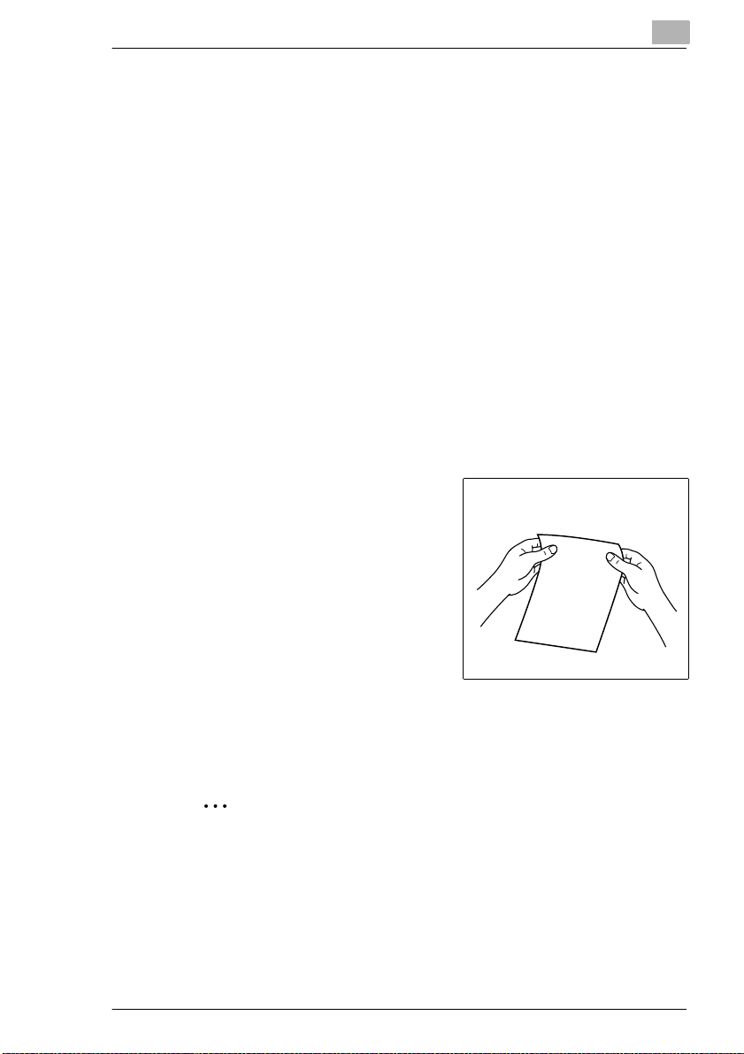
Original and copy
The original is the document being duplicat ed by the copy cycle.
Original
(document to be copied)
Copy cycle
enlarge,
shrink,
sort,
staple,
punch
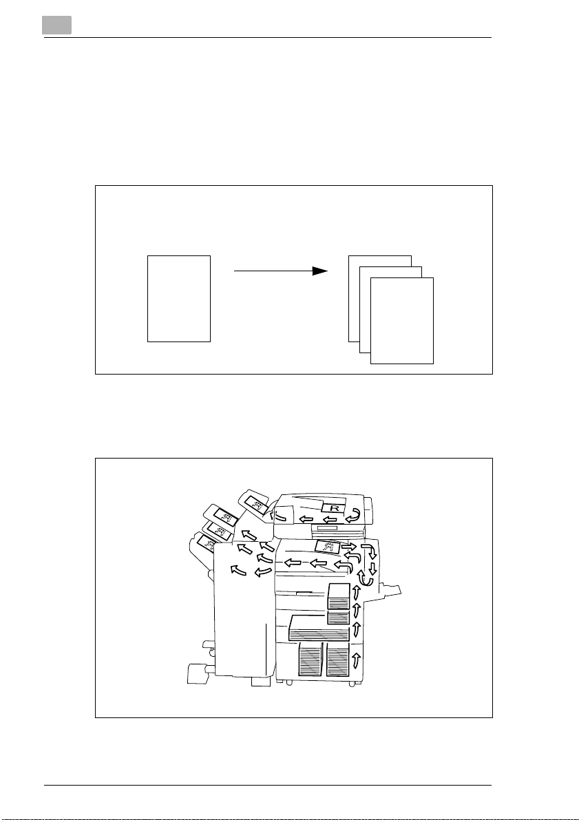
Feeding direction
The feeding dir ection is the path the paper takes through the co pier. The
feeding direction is shown by the arrows in the fol lowing illustr ation.
(copy of the ori ginal document)
Copy
1-8 Di251f/Di351f
Page 20
Introduction
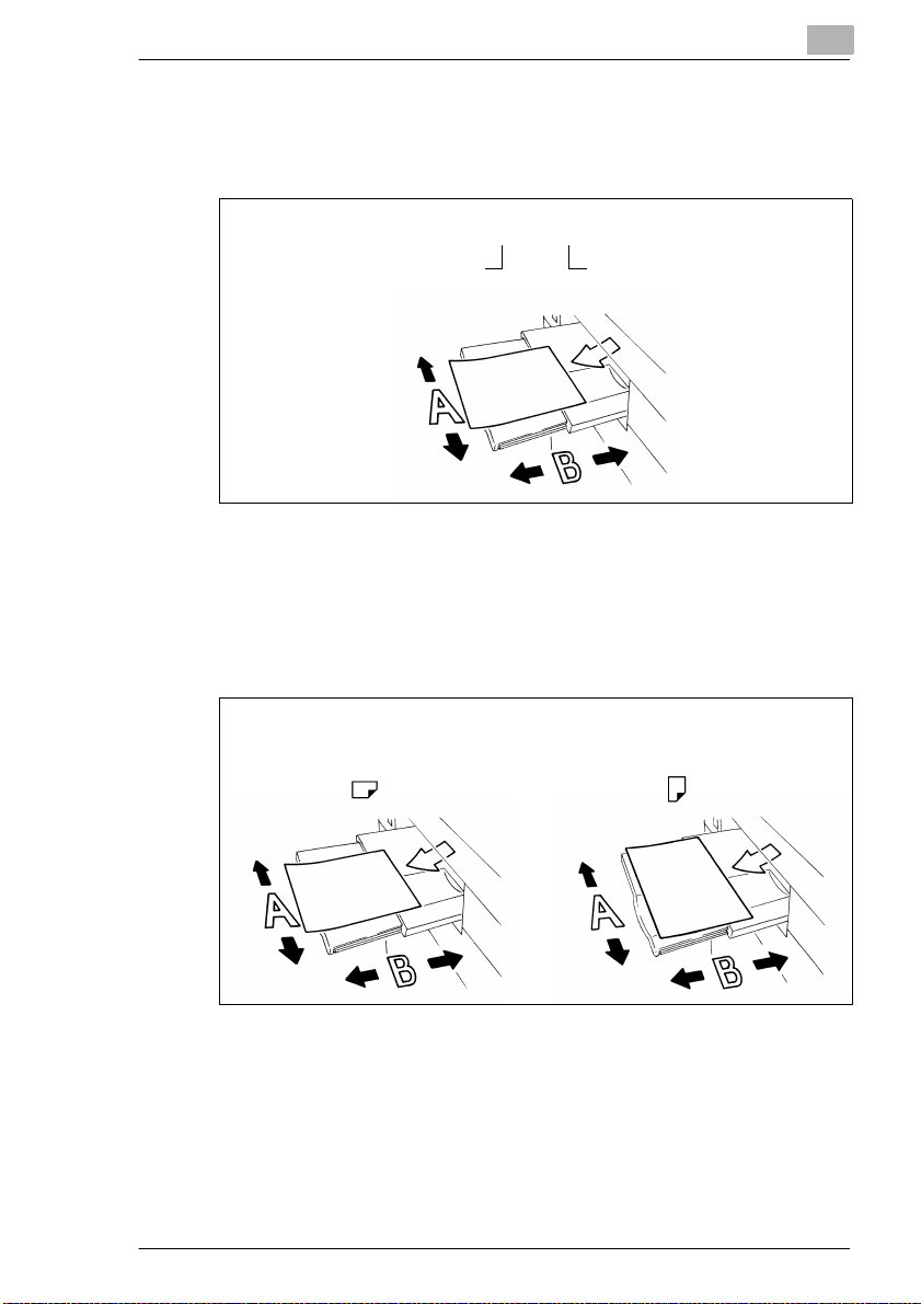
Width and length
When paper sizes are giv en, the first value is al ways the width of the paper
(side A). The second value i s the l ength of the paper (side B).
1
21 x 29.7 cm
Width of the paper
(side A)
Lengthwise and crosswise
If side A of the paper format is shor ter than side B, this is referr ed to as
lengthwise.
If side A of the paper format is longer than side B, this is referred to as
crosswise.
Length of the paper
(side B)
21 x 29.7 cm 29.7 x 21 cm
Lengthwise Crosswise
Abbreviation s are f requently placed after the paper sizes to indicate
lengthwise or crosswise more accurately:
G Lengthwise: L such asA4 L
G Crosswise: C such asA4 C.
Di251f/Di351f 1-9
Page 21

1
Introduction
1-10 Di251f/Di351f
Page 22
Getting to Know Your System
2 Getting to Know Your System
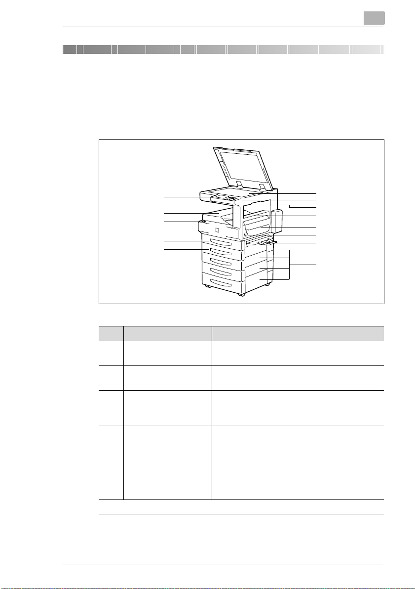
2.1 System Overview
Di251f/Di351f (external)
2
10
11
12
13
6
7
8
9
1
2
3
4
5
Item Name Description
1 Control Panel The control p anel has keys and indicators for
operating the system.
2 Standard Output Tray Receives the created copies, faxes and
printouts (max. 100 sheets of plain paper).
3 Power Switch The power switch is located beneath the cover.
Use the po wer swit ch to switch the system on
and off.
4 1st Paper Drawer
(Universal drawer)*
. . . continued on next page
* Universal paper drawers are variable in size and the operator can set them to hold different
sizes of paper.
This tray holds up to 250 sh eets of standard
paper (80g/m
paper.
• The LED blinks:
The paper drawer is almost empty.
• The LED is on, not blinking:
The paper drawer is empty.
2
) or up to 50 sheets of special
Di251f/Di351f 2-1
Page 23
2
Getting to Know Your System
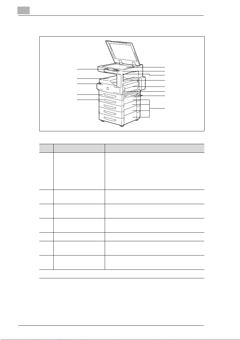
Di251f/Di351f (external)
1
2
3
4
5
Item Name Description
5 2nd Paper Drawe r This pa per drawer holds up to 500 sheet s of
standard paper (80g/m
• The LED bl inks:
The paper drawer is almost empty.
• The LED is on, not blinkin g:
The paper drawer is empty.
6 Original Glass Place the original face do wn on the original
glass.
7 Contrast Control Knob Use the cont rast control kn ob to change the
contrast on the touch screen.
8 Total Counter The counter shows the number of copies made
by the sy stem.
9 Upper Right Door Open thi s cover to clear a p aper misfeed.
10 Right Door (R1) Open this door t o change the imag ing uni t or
clear a paper jam.
11 La tc h for the Ri gh t
Door (R1)
. . . continued on next page
Pull this latc h t o op en the r ig ht do or (R 1).
6
7
8
9
10
11
12
13
2
).
2-2 Di251f/Di351f
Page 24
Getting to Know Your System
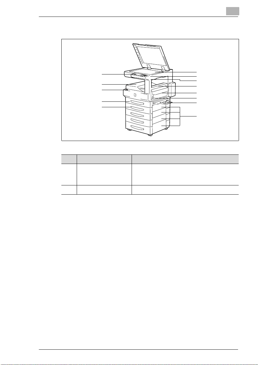
Di251f/Di351f (external)
2
10
11
12
13
6
7
8
9
1
2
3
4
5
Item Name Description
12 Single Feed Tray Use the si ngle feed tray to manually feed
indivi du al sheets, suc h as spec ia l pa pe r (OH P
sheets, thick paper, etc.) into the system.
13 Lower Right Doors Open these covers to clear paper misfeeds.
Di251f/Di351f 2-3
Page 25
2
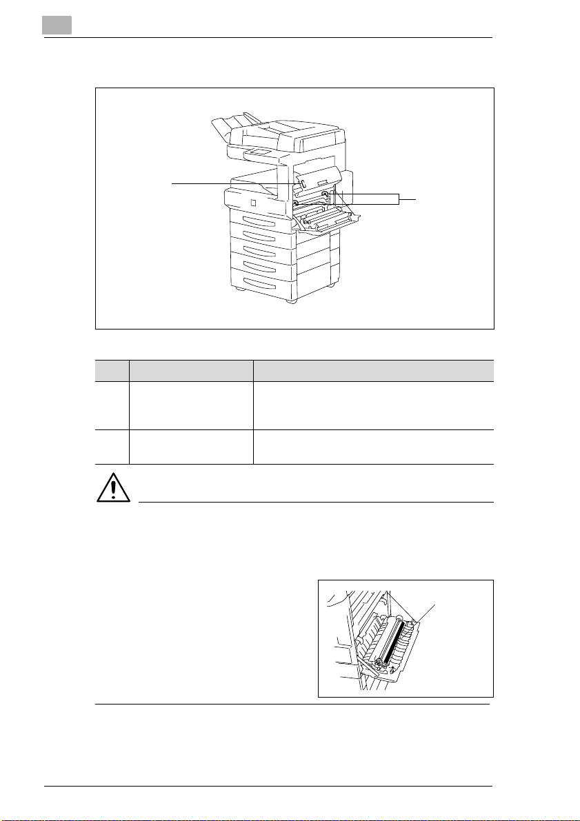
Di251f/Di351f (internal)
1
Item Name Description
1 Opening Button for the
Upper Right Door
Push this button to open the upper right door
and remove a pape r jam.
Getting to Know Your System
2
2 Gree n H oo ks Pull thes e hooks to remo ve the im aging unit
when you need to ch ange it.
CAUTION
Improper handling can affect the function of the system.
When the right door is open, the image transfer roller is accessible. If
touched, the function of this roller can be i mp aired.
➜ Never touch the image transfer
roller.
Image
transfer
roller
2-4 Di251f/Di351f
Page 26
Getting to Know Your System
2.2 Optional Equipment
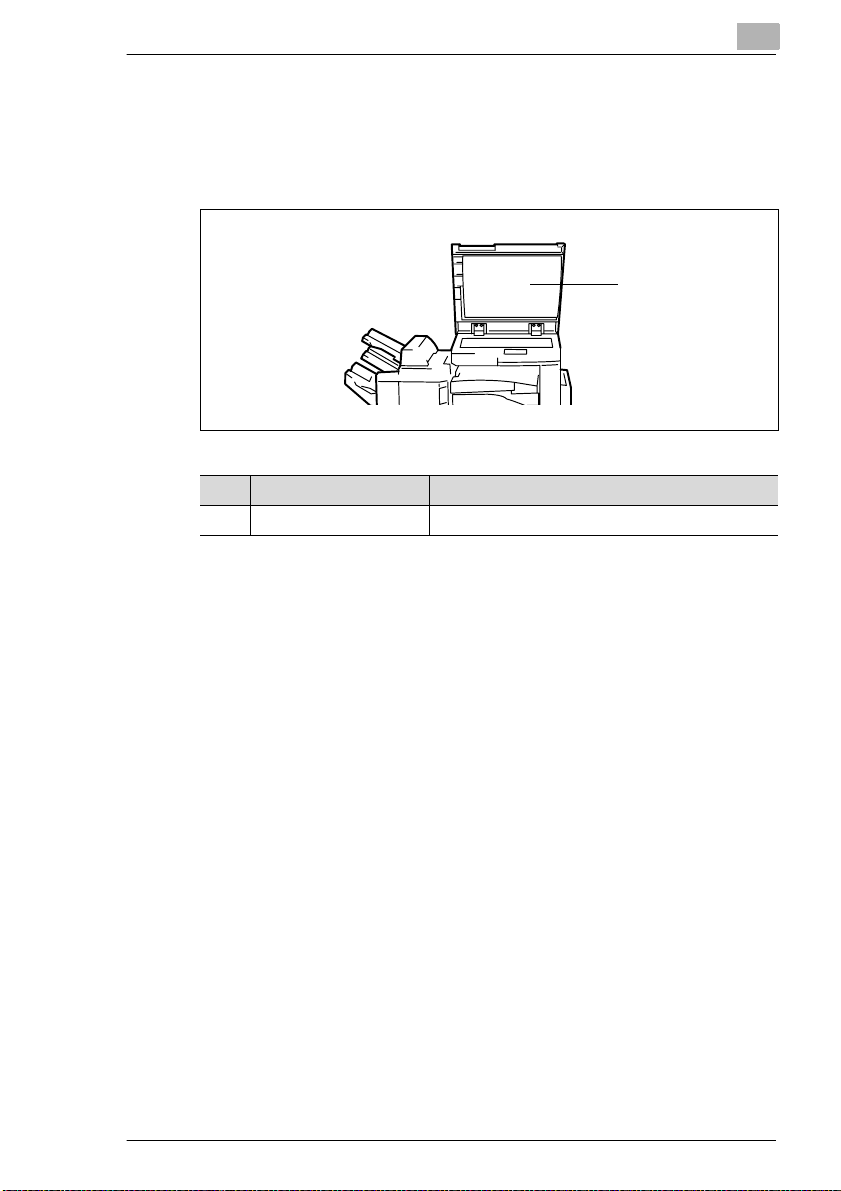
Original Cover OC-3
The original cover holds an original placed on the original glas s.
Item Name Description
1 Original Pad Holds an original placed on the original glass.
2
1
Di251f/Di351f 2-5
Page 27
2
Getting to Know Your System
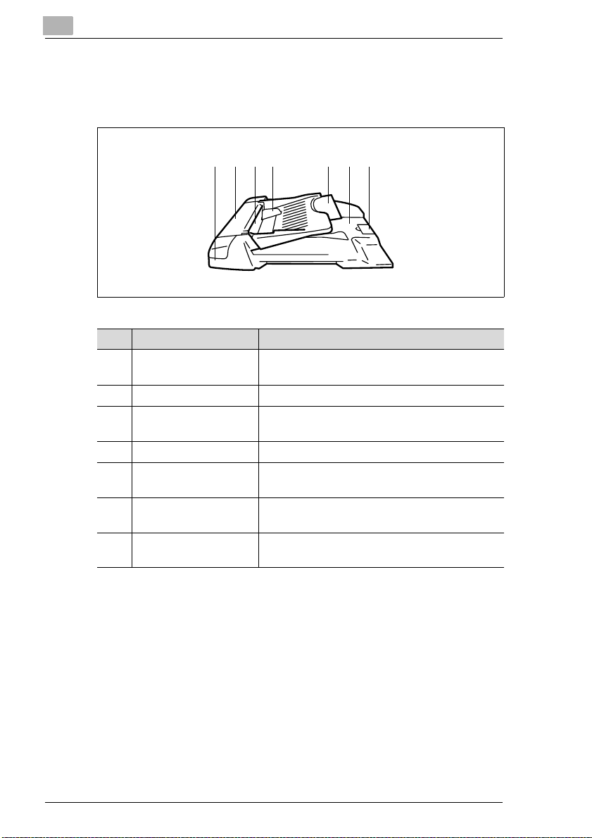
Automatic Document Feeder AF-9
The automatic do cument feeder ca n feed up to 70 ori ginal s in su cces sion
automatically.
21 3 5 74 6
Item Name Description
1 Status Indica to r Lights gree n w hi le a n ori gi na l is bei ng sc an ne d.
2 Original Misfeed Door Open this cover to cle ar a paper misfeed.
3 Document Feeder Place the originals on the document feeder with
4 Document Guide Plate Set the document guid es to the origina l size.
5 Document Feed Tray
Extender
6 Document Exit Unit Receives the originals after they have been
7 Original Stopper Pull up the stopper when processing large-s ize
Lights red if a malfunction has occurred.
the side to be scanned face up.
Pull out this extender when processi ng largesize originals.
scanned.
originals.
2-6 Di251f/Di351f
Page 28
Getting to Know Your System
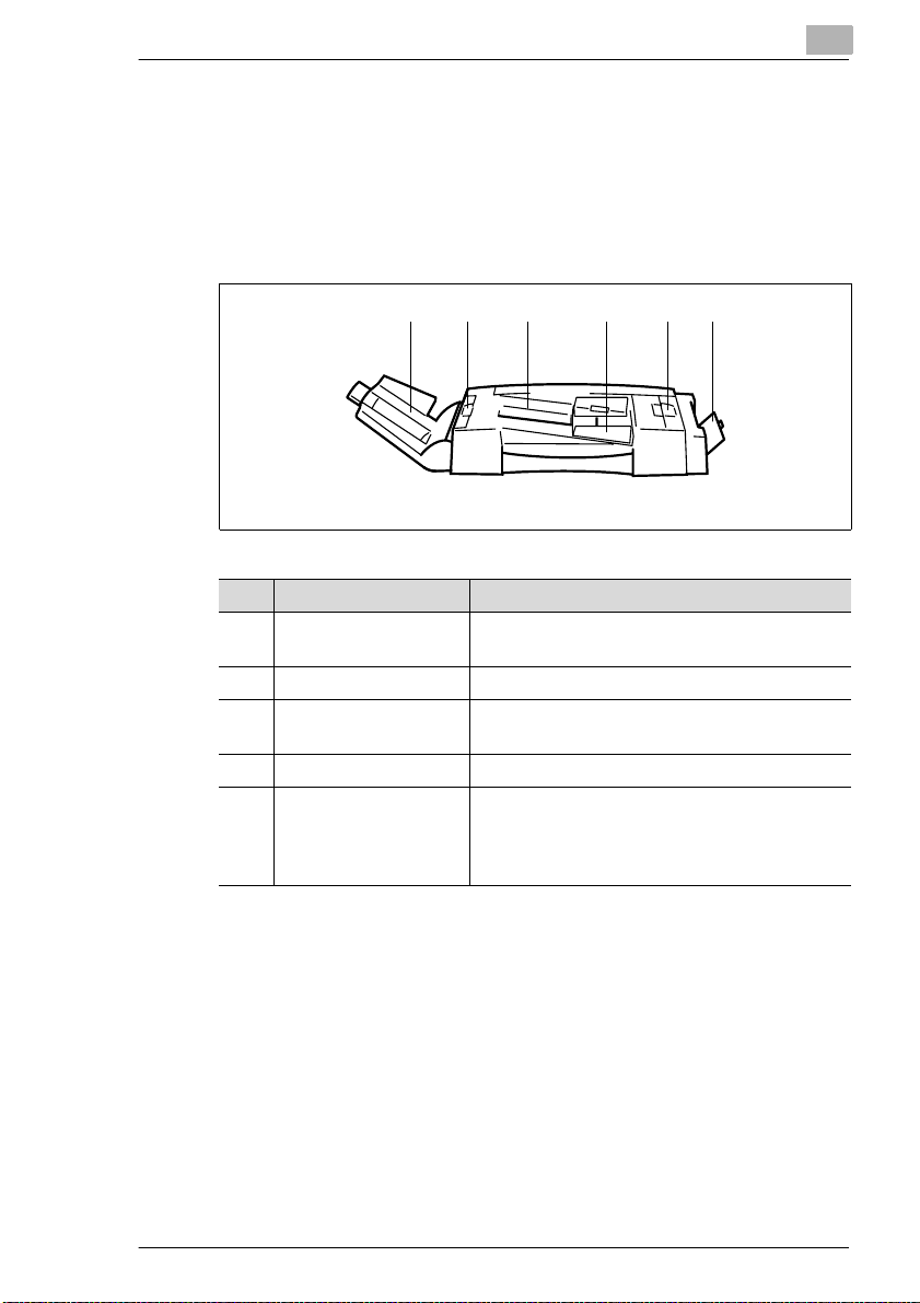
Duplexing Document Feeder AFR-17
The automatic do cument feeder can feed up to 50 ori ginal s in su cces sion
automatically. If two-sided originals are being copied, the duplexing
document feeder can also turn them over.
The single feed tray can be used for automatically feeding very thin or
heavy originals.
Item Name Description
1 Document Exit Unit Receives the originals after they have been
2 Original Misfeed Doors Open these covers to clear paper misfeeds.
3 Document Feeder Place the originals on the document feeder with
4 Document Guide Pla te Set the d ocument guides to the original size.
5 Sin gle Feed Tray
(SADF)
2
21 2 3 4 5
scanned.
the side to be scanned face up.
The sing le fe ed tra y allo w s yo u to pr o ce s s
thinner or thicker originals than with the
docume nt feeder . However, the originals must
be fed one by one.
Di251f/Di351f 2-7
Page 29
2
Getting to Know Your System
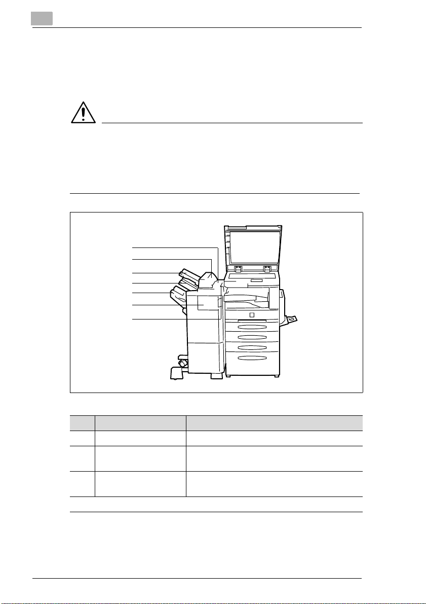
Finisher FN-109/FN-110
The finishers ena ble controlled finishing and stacking of printouts. The
finishers can sort , group and staple print outs. The FN-109 finisher also
permits punching printouts.
CAUTION
Damage to the system by improperly estimating the space re quired
The offset trays of a finisher move downward during the print cycle.
Objects below the offset trays may seriously damage them.
➜ Do not place any objects below t he offset trays of the fini sher.
1
2
3
4
5
6
7
Item Name Description
1 Upper Cover Open this cover to clear a paper misfeed.
2 Door for the Option
Tray
3 Option Tray (Optional)* This tray receives printouts that were sent to it
. . . continued on next page
* The option tray is an optional unit for the FN-109 and FN-110 finishers. The option tray can
be used only in combination with a printer controller.
Open this door to clear a paper ja m located in
the area of t he opti on tr ay .
from a PC.
2-8 Di251f/Di351f
Page 30
Getting to Know Your System
Finisher FN-109/FN-110
1
2
3
4
5
6
7
Item Name Description
4 Top Offset Tray Receives pri ntouts m ade on st andard o r heavie r
5 Bottom Offset Tray The printouts sorted with the offset function are
6 Front Door (FN4) Open the front door to clear a pa per misfeed.
7 Recessed Grip Use the recessed grip to pull the finisher away
2
paper.
fed out here.
from the system.
Option Tray JS-100
The option tray is an optional accessory for the FN- 109 and FN-110
finisher. The opti on tr ay can be used only in combination with a printer
controller for creating separate printouts.
Di251f/Di351f 2-9
Page 31

2
Getting to Know Your System
Mailbin Finisher FN-504
The finisher enables c ontrolled f inishin g and stack ing of pr intouts. Use the
finisher to sort, group, punch and stapl e pri ntouts.
(Only possible if a printer controller is installed.)
The printouts ca n be output t o one of five t rays assi gne d using a PC. The
printouts can be sorted, grouped or punche d.
45
3
2
1
Item Name Description
1 Five Copy Trays These trays receive the printouts that are
2 Bottom Offset Tray The printouts sorted with the offset function are
3 Top Offset Tray Receives pr intout s made on standar d or heavi er
4 Cover Panel for the
Upper T ray
5 Cover for the Stapler
Unit
6 Recessed Grip Use the recessed grip to pull the fin isher aw ay
assigned to them.
fed out here.
paper.
Open thi s cover to clear a paper misfeed.
Open this panel to clear a staple jam or
replenish staples.
from the system.
6
2-10 Di251f/Di351f
Page 32

Getting to Know Your System
Internal Finisher for Offset Tray OT-102
This finisher allows printouts to be output sorted or grouped.
Sorter JS-201
The sorter allows printouts to be output sort ed or gro uped.
2
Di251f/Di351f 2-11
Page 33

2
Getting to Know Your System
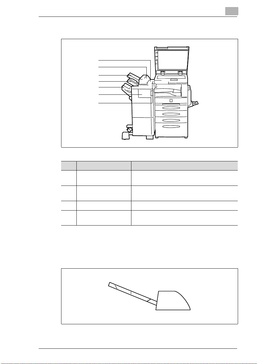
Duplex Unit AD-15
The duplex unit can turn the printed shee ts over for double-si ded printing.
A3L to A5 paper can be processed with the duplex unit.
2
1
Item Name Description
1 Dup le x Unit Th e duplex unit auto m at i c all y turns paper ov er
to enab le doub le-sided printing.
2 Latch Pull this latch to open the duplex unit and clear
a paper misfeed.
2-12 Di251f/Di351f
Page 34

Getting to Know Your System
Paper Drawer PF-118/PF-119
With an additiona l paper tray, you can increase th e paper capacit y of your
system.
Item Name Description
1PF-118
Paper D rawer
(Universal drawer)*
1PF-119
Paper D rawer
* Universal paper drawers are variable in size and the operator can set them to hold different
sizes of paper.
1
This paper drawer holds up to 500 sheets of
standard paper (80g/m
• The LED blinks:
The paper drawer is almost empty.
• The LED is on, not blinking:
The paper drawer is empty.
This paper drawer holds up to 500 sheets of
standard paper (80g/m
• The LED blinks:
The paper drawer is almost empty.
• The LED is on, not blinking:
The paper drawer is empty.
2
).
2
).
2
Di251f/Di351f 2-13
Page 35

2
Getting to Know Your System
Large Capacity Cassette PF-117
The large capacity cassette increases the paper capacity of the system.
The large capacit y cassette holds up to 2,500 sheets of plain paper
2
(80g/m
). The large capacit y cabinet is designed to hold A4C paper.
1
Item Name Description
1 Large Capacity
Cassette
The large capacity cassette holds up to 2,500
sheets of plain paper (80g/m
2
).
2-14 Di251f/Di351f
Page 36

Getting to Know Your System
Copy Table
Use the table to adjust the height of the syst em , for exampleto connect a
finisher.
Paper Feed Cabinet
Use the cabinet t o adjus t the hei ght of the sys tem, for ex ampleto connect
a finisher.
2
Memory Expansion Module
The memory expansion modul e can increase the system me mo ry by
8MB, 16 MB or 32MB.
If you process material that requires a large amount of system memory,
you may want to increase the system memory, which allows the system
to process more data cont inuously.
Printer Controller Pi3502
The printer c ontroller allows the system to be used as a computer printer.
Di251f/Di351f 2-15
Page 37

2
2.3 The Safe Use of Your System
The improper use of your system may result in health hazards, electrical
shock or even f ires. Please obse rve the f ollowing p rec aution s for the saf e
use of your system.
DANGER
Incorrect handling of the system can result in fi re and/or electri cal
shock!
The system is equipped wi th hi gh-voltage components. Incorrect use of
the system may result in fire or electrical shock. Observe the following
safety precaut ions to prevent injury and system damage.
➜ Never use flammable sprays, liquids or gases near the system.
➜ Never remove any safety equipment.
➜ Never make structural modifications to the system.
➜ Connect the system to the power supply using only the power cord
provided.
➜ Ensure that the power sup ply provides the corre ct supply voltage for
the system.
➜ Never unplug the system with wet hands.
➜ Do not place coffee cups, bot tles or other contain ers with liquids on the
system. In the event that liquids are accidentally introduced into the
system, switch the system off immediately. Unplug the power cord.
Consult your technical representative.
➜ Never insert pap er clips, st aples or ot her small pieces of metal in to the
openings of the system . If me tal objects are accidentally introduc ed
into the system in spite of all precautions, switch the system off
immediately. Unplug the power cord. Consult your technical
representative.
➜ Do not dispose of empty toner bottles into an open fire.
➜ Do not touch areas designated with safety labels.
➜ Store supplies, such astoner, out of the reach of children.
➜ Make sure the system has a stable base and cannot tip over.
Getting to Know Your System
DANGER
Incorrect handling of the power cable can result in fire and/or
electrical shock!
The system is equippe d with high- voltage c omponents . Incorrect handlin g
2-16 Di251f/Di351f
Page 38

Getting to Know Your System
of the system’s power cable may cause damage to the cable. This could
result in fire and/or cause electrical shock. Observe the following safety
precautions to prevent injury and syste m damage.
➜ Be sure that the power cabl e is not damaged . If it becomes damaged ,
switch off the system immediately. Unplug t he power cord. Consult
your technical representative.
➜ Do not pull directly on the power cable itself when unplugging the
power cord from the power outlet.
➜ Do not move the system unless it is unplugged.
➜ Never place heavy objects on the power cable.
➜ Do not pull or bend the power cable.
➜ Do not place the system on cables belongi ng to other devices.
➜ Ensure that no cables of other devi ces get pinched in the system.
➜ Be sure that the power cord sits correctly in the power outlet.
➜ Be sure that the power outlet is visible and accessible at all times.
➜ Do not use any extension cords. If you require an extension cord to
connect the system to a power supply, contact your technical
representative.
➜ Never connect the system to a multiple-socket extension cord.
➜ Unplug the power cord at least once a year . Cl ean off any dust that
may have accumulated on or around the contacts.
2
Di251f/Di351f 2-17
Page 39

2
Getting to Know Your System
DANGER
System overheating can result in fire and/or electrical shock!
The system is equipped wi th hi gh-voltage components. Incorrect use or
faulty operat ion of the system may cau se the system to overh eat. Observe
the following safety precautions to prevent injury and system damage.
➜ Switch the sy stem of f immediat ely i f i t beco mes un usual ly h ot. Unp lu g
the power cord. Consult your technical representative.
➜ Switch the sys tem off i mmediately if smoke co mes out of it. Unplu g the
power cord. Consult your t echnical representative.
➜ Switch the system off immediate ly if it emits an unusual odor. Unplug
the power cord. Consult your technical representative.
➜ Switch the system off i mmediatel y if it is dam aged in an y way. Unplug
the power cord. Consult your technical representative.
➜ Always unplug the power cord when the system is not going to be used
for a long time.
➜ Make sure the ventil ation slots on the system are not covered.
2-18 Di251f/Di351f
Page 40

Getting to Know Your System
CAUTION
Incorrect handli ng can cause damage to the system!
Incorrect handling can cause damage to the sys tem. Observe the
following safety precautions to prevent system damage.
➜ Never place objects of more than 3 kg on the system.
➜ Do not lean on the touch screen.
➜ Never place objects on the touch screen.
➜ Do not copy clipped or stapled paper , car bon-backed originals or
aluminum-coated paper.
➜ Never open any doors while the system is faxing or copying.
➜ Do not turn the system off while it is faxing or copying.
➜ Do not drop the toner unit or imaging drum.
➜ Do not throw the toner unit or imaging drum.
➜ Use the system only for the tasks described in this manual.
CAUTION
A negligible amount of ozone is genera ted during the print cycle.
The ozone given off by the system is not hazardous to health, but it may
smell unpleasant . For a comfortable, heal thy and safe operating
environment, it is recomm ended that the room be well vent il ated.
➜ Locate the system in a well-ventilated room.
2
Di251f/Di351f 2-19
Page 41

2
Getting to Know Your System
CAUTION
External influences can cause damage to the system and system
supplies!
Observe the following safety precauti ons to prevent syste m damag e.
➜ Do not subject the system to vibrations.
➜ Do not subject the system or its supplies to extreme changes in
temperature or humidity.
➜ Use only distilled water for humidifiers run in the same room as the
system.
➜ Be sure to maintain the ambient conditions required for system
operation.
➜ Be sure the e nvi ronment in whi ch the sy st em and i ts suppl ies ar e k ept
is free of dust, soot, steam, sprayed water or any other potentially
damaging influen ces.
➜ Never bring any magneti sed object near the system.
➜ Never place objects of more than 3 kg on the system.
➜ Do not place toner units or imaging drums near floppy disks,
timepieces or other objects that are sensitive to magnetism .
➜ Always store toner unit s in a horizontal posi ti on.
➜ Do not subject toner uni ts, i maging drums or other sy st em supplie s to
direct sunlight, high temperatur es or dampness.
➜ Do not remove the protective packaging from supplies until you use
them.
2-20 Di251f/Di351f
Page 42

Getting to Know Your System
Laser Safety
This system is equip ped wit h a laser. If the system is operated in
accordance with th e instructions in t his manual, the laser poses no
possibility of danger.
The laser radiation is completely confined within the machine housing.
The laser beam cannot escape the housing at any time of oper ation.
This system is certif ied as a Class 1 laser product. This means that the
system does not generate any hazardous laser radiation.
Internal Laser Radiation
Mean radiant power at the laser aperture of the print head unit:
Di251f 19.5 µW
Di351f 27.8 µW
Wavelength:
Di251f 770 - 795 nm
Di351f 775 - 795 nm
This system oper ates u sin g a Clas s I IIb lase r di ode t hat em its a n invi sibl e
laser beam. The las er diode and scanni ng polygon mirror are incorporated
in the print head unit.
The print head unit is NOT A FIELD SERVICE ITEM. It may not be opened
under any circumstances.
2
Print he ad
The illustration to the left shows the location of the print head withi n the
system .
The illustrati on to the right shows the laser aper ture on the print head.
(Illustrat ed here with the right door open and the im aging unit removed.)
Di251f/Di351f 2-21
Laser Aperture
Page 43

2
Getting to Know Your System
DANGER
Hazardous laser radiation!
Operating the system in a manner that does not conform to t he
descriptions pr ovi ded in t his manua l c an lead t o the re lease of haz ardous
radiation.
➜ Operate the system only i n accordance with the instructions provided
in this manual.
This is a semiconductor laser system .
The maximum radiation capacity of the laser diode is:
Di251f 5mW
Di351f 15 mW.
The wavelength is:
Di251f 770 - 795 nm
Di351f 775 - 795 nm
Noise Emission
Device Noise Control Regul ations 3 GSGV, 1/18/199 1: The acoustic
noise at the operator’s workplace is equal to or less than 70dB(A),
according to EN 27779.
2-22 Di251f/Di351f
Page 44

Getting to Know Your System
Safety Lab el
Safety labels indicate hazard areas.
➜ Use this operating manual to familiarise yourself with the hazards
before carrying out any activity in a hazard area.
Safety label on the heating unit
The safety label is l ocated insi de the system at the posi tion marked below.
2
WARNING
Danger of burning from the heating unit!
The system heating uni t may reach temperatures of up to 120°C.
➜ Never touch the heating unit.
➜ Do not touch areas designated with thi s sym bol: : .
Di251f/Di351f 2-23
Page 45

2
Getting to Know Your System
Safety Label inside the syst em
The safety label is l ocated insi de the system at the posi tion marked below.
DANGER
Danger! High Voltage!
Improper operat ion of the system can result in personal injury caused by
electric shoc k.
➜ Operate the system only i n accordance with the instructions provided
in this manual.
2-24 Di251f/Di351f
Page 46

Getting to Know Your System
Safety label on the back of the syste m
The safety label is located on the back of the system at the position
marked below.
CLASS 1 LASER PRODUCT
LASER KLASSE 1
PRODUCT
DANGER
Hazardous laser radiation!
Improper operation of the system can result i n release of dangerous
radiation.
➜ Operate the system only in accordance wit h the instr uctions prov ided
in this manual.
2
Di251f/Di351f 2-25
Page 47

2
220-240
1250-1400
50-60
6
Di251f
MINOLTA CO.,LTD
0000003
MADE IN CHINA
N87
220-240
1250-1400
50-60
6
Di351f
MINOLTA CO.,LTD
0000003
MADE IN CHINA
N87
Getting to Know Your System
Data on the Manufacturer’s Name Plate
The manufacturer’s name plate for the system is located on the back of
the system at the position marked below.
Di251f
Di351f
The following data are pr ovided on the manufacturer’s name plate:
Model n ame
Power req uirement da ta
Max. power consumption Rated current data
Certifications
Serial number of the system
Manufacturer Country where
manufactured
For further infor mation on the certificat ions on the manufactu rer’s name
plate, see page 10-24 .
Write down the model name and serial number, which are speci fied on the
type label, in the table bel ow.
Model:
2-26 Di251f/Di351f
Serial No.:
Page 48

Getting to Know Your System
2.4 Transporting the System
If you need to transport the system, please consult your technical
representative.
2.5 Setting up the System
Environmental Requirements
The optimal environm ental requirements of the system are as follows.
G Temperature from 10°C to 32°C
(maximum fluctuat ion of 10°C per hour)
G Humidity of 15% to 85%
(maximum fluctuat ion of 10% per hour).
Installation Site
The installation site must meet the followi ng requirements:
G An area that is dry and free of dust
G A level surface free of undue vibrations
G Free from flammable gases such as ammonia
G Provision for good ventilation
G A location away from curtai ns or other easily ignited materials
G Away from personnel so that n o one is subject ed to the direct exhaust
air of the system.
The system must be protected from the following influences:
G Splashing liquids
G Direct sunlight
G Strong temperature fl uctuations
G Direct airflow from heating or air conditioning units.
2
Di251f/Di351f 2-27
Page 49

2
Getting to Know Your System
Space Requirements for the System
Be sure to al low a clear ance of 150 mm or more behin d the unit. This will
ensure good vent i lation. Furthe rmor e, al low a c lea rance of about 310mm
between the right side of the cabinet and the wall to provi de sufficient
access for changing the toner bottle .
Scale: mm
1670
1484
Front view Side view
1058
This information i s applicable to the basic system, includin g AFR-17, FN504, PF-118, PF-119 and AD-15.
Storing Supplies
Ensure that supplies are stored:
G In their sealed original packagi ng m aterials
G Protected f rom direct sunlight and heat sources
G In a cool, dry, dust-free location
G Out of the reach of chil dren.
WARNING
Toner can be hazardous to your health!
Toner is harmful if swallowed.
➜ If you get any toner on you r hands, i mmediately was h them th oroughly
with soap and cold water.
2-28 Di251f/Di351f
Page 50

Getting to Know Your System
2.6 Connecting the power cord and phone cable
Connecting the phone cable
Plug the standard phone li ne
1
connector into the jack on the
system.
Connect the TAE connect or to the
2
phone jack on the left “N” slot.
Connecting the power cord
The system needs a reliable, consistent power supply. Please cal l your inhouse technical support if required.
The allowable values for the power supply and the frequency range can
be found in the technical information. For more i nformation, see
page 10-7.
➜ Plug the power cord into the corresponding jack on the system and
into the wall outlet.
N
F
2
N
Di251f/Di351f 2-29
Page 51

2
Getting to Know Your System
2.7 Switching the system on and off
Switching the System On
➜ Press the power switch to the ON
position.
The [START] indicat or key on the
control panel is red.
After a few seconds the following
message is shown on the touch
screen:
"Now warming up. Ready to scan".
The indicator on the control panel
button lights green. If you start a
cycle, the printouts are output automatically after the warm up phase
has elapsed.
✎
Warm up time!
At an ambient temperature of 23°C, the Di251f requires about
60 seconds to warm up. The Di351f requires about 70 seconds to
warm up.
ON
OFF
After switching on the system, all functions are at their defau lt settings.
When the system is shipped, the following default settings appl y:
G Number of printouts: 1
G Paper Feed: Auto Paper Mode
G Zoom Factor: ×1.000
G Exposure: Auto Exposur e M ode (Text Mode)
G Finishing: Non-sort
G Copy mode: From 1-sided original to 1-sided copy.
You can change the default settings in the User's Choice. For more
information, see page 8-1 and the following pages.
2-30 Di251f/Di351f
Page 52

Getting to Know Your System
Switching the System Off
➜ Press the power switch to the OFF
position.
The touch screen indi cator is no
longer lit up. The system is switche d
off.
✎
Help save energy!
The system has several energy-saving functions:
Energy Save Mode:
Energy save mode is automati cally activated approximately 15
minut e s afte r the last acti vi ty .
Auto Shut Off (Sleep M o d e ):
The system is switched to sleep mode approx imately 60 minut es after
the last activit y. In sleep mode, the system uses less power than in
Energy Save mode.
2
ON
OFF
The idle time before ener gy save mode is automat icall y acti vated can
be changed in the User’s Choice settings. For more informatio n, see
page 8-8 and the following pages.
Di251f/Di351f 2-31
Page 53

2
Getting to Know Your System
2.8 Control Panel Keys and Indicators
Overview
1235
4
1213
Item Name Element Description
1 Touch Screen – Touch-sensitive control panel
2 Utility Key Use t his to call up various utilities.
3 Mode Check Key with
4 Pause Key Use this to set a dial pause.
5Copy mode Key with
6 Fax/scan mode Key with
7 Keypad Keys Setting values
8 Only active if administrator numbers have been set up:
Access
(Access Mode Key)
9 Interruption Key with
. . . continued on next page
indicator
indicator
indicator
Key Use to confirm a specified access
indicator
Calls up an overview of the current
system settings an d calls up the copy
program functions.
Activate copy mode.
• Indicator lights up:
Copy mode is active.
Use this to start fax or scan mode.
code.
Interruption of a copy cycle.
• Indicator lights up:
Copy cycle is interrupted.
10
11
6
7
8
9
2-32 Di251f/Di351f
Page 54

Getting to Know Your System
2
1235
4
6
7
8
9
10
11
1213
Item Name Element Description
10 C (Clear ) Key Delete values and settings using the
11 Panel Reset Key Resets system to default settings.
12 Stop Key Stops a copy or sc an cycle.
13 Start Key with
indicator
numeric keypad.
Start s a cycle.
• Indica tor lights up gree n:
The system is ready for operation.
• Indicator li gh ts up red:
The system is not ready for
operation.
Di251f/Di351f 2-33
Page 55

2
Getting to Know Your System
The Touch Screen
When you switch the system on or r eset the system, a priori ty screen is
displayed. There are three priority screens. You can specify ac cording to
your needs which priority screen appears in the User’s Choice setting s.
For more information, see page 8-14.
Priority screen Indicator on the Touch Screen
Auto
For additional
information, see
page 2-37.
Copier
For additional
information, see
page 2-39.
Fax
For additional
information, see
page 2-41.
2-34 Di251f/Di351f
Page 56

Getting to Know Your System
Important Icons in the Display
Display Panel Meaning
Scan The document is being read.
Waiting for redial The system is waiting for a redial.
Dialling The fax number is being dialed.
Receiving The system is receiving a fax.
Sending The system is sending a fax.
Copying Copies are being created.
Printin g Printo ut s ar e bein g cr e a t ed .
Protected document A protected document is in the mailbox.
Waiting for call The system is wa iting for a call.
Broadcast A document is saved as a broadcast
Receiving data from PC Data are being loaded into the system
Data not receiv ed PC print data stu ck in me m ory .
2
document.
from a PC.
Waiting for pr int job A document is being prepared for
Auto Receive OFF The system is set to manual receiv e.
No paper Load paper into the system.
No toner Replace the toner bottle.
Drum used up Replace the imaging unit.
Service Call customer service for regular
Access restriction The system is available only after
printing.
servicing.
entering a valid access number.
Di251f/Di351f 2-35
Page 57

2
2.9 The Touch Screen
Operating the Touch Screen
CAUTION
Incorrect handling can cause damage to the system!
The touch screen surface is glass. Incorrect handling can cause damage
to the touch screen.
➜ Never place heavy objec ts on the touch screen.
➜ Always touch the surface of the touch screen carefully.
➜ Do not press hard on the surface.
➜ Do not bring pointed object s into contact with the surfa ce of the touch
screen.
The system is equipped wi th a to uch screen. A touch screen is a display
that is sensitiv e to the touch. You can use the touch screen to adjust
system settings and control cycles.
➜ You can select a function or make settings by l ightly touchi ng a key on
the touch screen.
Getting to Know Your System
✎
Touch screen displays may be different!
The displays on the touch screen partly depend o n the equi pm ent of
the system. The displ ays shown in this user manual may be slightly
different from the displays on your syst em .
2-36 Di251f/Di351f
Page 58

Getting to Know Your System
The "Auto" Priority Screen
Item Name Element Description
1 Display Panel Indicator Shows messages and entered
2One-touch
destinations/fax
programs
3 Copy program Key Calls up the first copy job program.
4 Supplementary
display
2
1
2
3
4
numbers.
Key Calls up the first four one-t ouch
destinations or fax programs.
Indicator Displays free system memory.
Key for calling up the job list.
Displays icons pertaining to the current
system status.
Di251f/Di351f 2-37
Page 59

2
Getting to Know Your System
If you have set the stan dard screen to "Auto," the system recognises
whether you are copying or faxing by your input on the numeric keypad.
By default, the Auto sc reen displays the fi rst four fax progr ams and the first
copy job program. This setting can be customised for you by a technical
representative.
➜ Di251f
Entering a one or two-digit number
activates copy mode.
Entering a number consisting of
three or more digits activates fax
mode.
➜ Di351f
Entering a one t o three-digit num ber
activates copy mode.
Entering a number c onsisti ng of four or m ore digits act ivates f ax mode.
✎
Fax mode or copy mode?
Press the [FAX/SCAN M ODE] or [COPY M ODE] but ton on the co ntr ol
panel to switch to the desi red mode.
2-38 Di251f/Di351f
Page 60

Getting to Know Your System
The "Copier" Priority Screen
Item Name Element Description
1 Index Keys Opens an index card with specific
2 Display Panel Indicator Shows messages and the number of
3 Basics menu Keys Recalls the basic copier settings.
4 Current settings Indicator Indicates current copier settings.
5 Supplementary
display
2
1
2
3
4
5
copier settings .
• Basics
• Original > Copy
• Density
• Auxiliary functions
copies.
• Paper
• Zoom
• Finishing
Indicator Displays free system memory.
Key for calling up the job list.
Displays icons pertaining to the current
system status.
Di251f/Di351f 2-39
Page 61

2
Getting to Know Your System
The "Copier" default screen contains f our tab keys.
You can switch between four setting screens usin g these tab keys.
Settings Screens Indicator on the Touch Screen
Basics
For more information,
see page 4-1.
Orig.>Copy
For more information,
see page 4-42.
Density
For more information,
see page 4-57.
Auxiliary
For more information,
see page 4-61.
2-40 Di251f/Di351f
Page 62

Getting to Know Your System
The "Fax" Priority Scre en
2
1
6
2
3
4
5
Item Name Element Description
1 Index Keys Opens an index card with specific
copier settings .
• One-touch
• Abbr.#
• 10-key Dialling
• Qualit y & re du ct i o n
• FAX menu
2 Special dial mode Keys Use these keys to select a special dial
mode (on-hook dial, chain dial) .
3 Index Keys Use to sel ect the ta b pag e. Th ese ke ys
call up a tab list for sele cting a tab
page.
4One-touch
destinations/fax
programs
5 Supplementary
display
6 Display Panel Indicator Displays the dialled phone number.
Keys Call up one-t ouch de stina tion s and fax
programs.
Indicator Displays free system memory.
Key for calling up the job list.
Displays icons pertaining to the current
system status.
Di251f/Di351f 2-41
Page 63

2
Getting to Know Your System
The "Fax" default screen contains five tab keys.
You can switch between five setting screens using these tab keys.
Settings Screens Indicator on the Touch Screen
One-Touch
For additional
information, see
page 7-1.
Abbr.#
For additional
information, see
page 7-11.
10-Key Dialling
For additional
information, see
page 7-15.
Quality & Reduction
For additional
information, see
page 7-18.
2-42 Di251f/Di351f
Page 64

Getting to Know Your System
Settings Screens Indicator on the Touch Screen
FAX menu
For additional
information, see
page 7-26.
2
Di251f/Di351f 2-43
Page 65

2
2.10 Adding Paper
If the currently se lected paper drawer is empty . . .
G A message is displ ayed on the touch screen.
G The current pr ocess is stopped.
G The empty drawer blinks.
➜ Add copy paper to the empty paper tray. An interrupted fax or print
cycle is then resumed automatical ly. To resume a copy cycle, you
have to press the [START] button on the control panel.
Getting to Know Your System
✎
Receiving a fax if paper runs out or jams:
If paper runs out or jams while receiving a fax, the data are
automa tically writt e n to sy s te m m e mo ry. If memory is full , th e
incoming fax is aborted. Further faxes cannot be received unti l
sufficient memory becomes availabl e. If the paper jam is cleared or
paper replenish ed, the fax is automaticall y printed from memory .
2-44 Di251f/Di351f
Page 66

Getting to Know Your System
Filling the 1st Drawer
The 1st drawer is a universal drawer.
The universal drawe rs can be set for different paper sizes.
Note the following important information!
Capacity: 250 sheets of plain paper (80g/m
Types of pape r : Plain pa per, recycle d pa pe r (60 g/ m
Paper sizes: A3L to A5 (fixed setting)
CAUTION
Incorrect use can cause the system to malfunction!
Touching the f eed rolle rs in the paper drawer s can soil their surf aces. Thi s
can cause incorrect feeding.
➜ Never touch the feed roller.
50 sheet s of spec ial paper
2
Thick pa per (91g/m
OHP transparencies, labels
up to 160g/m2)
2
)
2
up to 90g/m 2)
2
Carefully pull the paper drawer out
1
as far as it will go.
Press the paper lifting plate down
2
until it lock s .
Di251f/Di351f 2-45
Feed roller
Page 67

2
Position the paper between the
3
paper size guides. The side that is
to be printed must be up.
Did you load special paper
?
(OHP films, labels, etc. )?
➜ Before starting the printout,
be sure to set the correct paper
type. For more information,
see page 4-4.
Ensure that the maximum paper
4
filling height is not exceeded (see
mark on insi de of t he paper drawer ).
Adjust the paper guides to fit the
5
size of the loaded paper exactly.
Did you load a custom paper
?
size?
➜ Before starting the printout,
be sure to set the
paper size. For more
information,
see page 4-6.
Getting to Know Your System
Close the paper drawer carefully.
6
2-46 Di251f/Di351f
Page 68

Getting to Know Your System
Filling the 2nd Drawer
This paper drawer is desig ned to hol d one paper size.
This drawer can be modified by a technical representative to hold a
different paper size.
Note the following important information!
Capacity: 500 sheets of plain paper (80g/m
Types of pape r : Plain pa per, recycle d pa pe r (60 g/ m
Paper sizes: A3L to A5 (fixed setting)
CAUTION
Incorrect use can cause the system to malfunction!
Touching the f eed rolle rs in the paper drawer s can soil their surf aces. Thi s
can cause incorrect feeding.
➜ Never touch the feed roller.
2
Thick pa per (91g/m
OHP transparencies, labels
up to 160g/m 2)
2
)
2
up to 90g/m 2)
2
Carefully pull the paper drawer out
1
as far as it will go.
Press the paper lifting plate down
2
until it lock s .
Di251f/Di351f 2-47
Feed roller
Page 69

2
Position the paper between the
3
paper size guides. The side that is
to be printed must be up.
Ensure that the maximum paper
4
filling height is not exceeded (see
mark on insi de of t he paper drawer ).
Close the paper drawer carefully.
5
Getting to Know Your System
2-48 Di251f/Di351f
Page 70

Getting to Know Your System
Filling the PF-119 Paper Drawer (Optional)
This paper drawer is desig ned to hol d one paper size.
This drawer can be modified by a technical representative to hold a
different paper size.
Note the following important information!
Capacity: 5 00 she et s of st an da r d pa pe r
Types of pape r : Plain pa per, recycle d pa pe r (60 g/ m
Paper sizes: A3L to A4 (fixed setting)
CAUTION
Incorrect use can cause the system to malfunction!
Touching the f eed rolle rs in the paper drawer s can soil their surf aces. Thi s
can cause incorrect feeding.
➜ Never touch the feed roller.
Carefully pull the paper drawer out
1
as far as it will go.
2
up to 90g/m 2)
Feed roller
2
Press the paper lifting plate down
2
until it lock s .
Di251f/Di351f 2-49
Page 71

2
Position the paper between the
3
paper size guides. The side that is
to be printed must be up.
Ensure that the maximum paper
4
filling height is not exceeded (see
mark on insi de of t he paper drawer ).
Close the paper drawer carefully.
5
Getting to Know Your System
2-50 Di251f/Di351f
Page 72

Getting to Know Your System
Filling the PF-118 Paper Drawer (Optional)
This paper drawer is a universal drawer.
The universal drawe rs can be set for different paper sizes.
Note the following important information!
Capacity: 5 00 she et s of st an da r d pa pe r
Types of pape r : Plain pa per, recycle d pa pe r (60 g/ m
Paper sizes: A3L to A4 (variable setting)
CAUTION
Incorrect use can cause the system to malfunction!
Touching the f eed rolle rs in the paper drawer s can soil their surf aces. Thi s
can cause incorrect feeding.
➜ Never touch the feed roller.
Carefully pull the paper drawer out
1
as far as it will go.
2
up to 90g/m 2)
Feed roller
2
Press the paper lifting plate down
2
until it lock s .
Di251f/Di351f 2-51
Page 73

2
Adjust the side paper guides to fit
3
the size of the paper.
How do the paper guides come
?
out?
➜ Gently push the paper guides
toward the system and l ift the far
end out of its guide.
Position the paper between the
4
paper size guides. The side that is
to be printed must be up.
Ensure that the maximum paper
5
filling height is not exceeded (see
mark on insi de of t he paper drawer ).
Getting to Know Your System
1
2
4
3
Adjust the side paper guides to fit
6
the size of the loaded paper.
Close the paper drawer carefully.
7
2-52 Di251f/Di351f
Page 74

Getting to Know Your System
Filling the PF-117 Large Capacity Cassette (Optional)
This paper drawer is desig ned to hol d one paper size.
This drawer can be modified by a technical representative to hold a
different paper size.
Note the following important information!
Capacity: 2,500 sheets of plain paper (80g/m
Types of pape r : Plain pa per, recycle d pa pe r (60 g/ m
Paper sizes: A4 C, LetterC, B5C<
Carefully pull the paper drawer out
1
as far as it will go.
2
)
2
up to 90g/m 2)
2
First insert paper into the right half
2
of the paper dr awer. The side that is
to be printed must be up.
Position the long sid e of the paper
3
stack at the right-hand side of the
paper drawer.
Ensure that the maximum paper
4
filling height is not exceeded (see
mark on inside of the paper dr awer).
Di251f/Di351f 2-53
Page 75

2
Place another stack of paper into
5
the left half of the paper drawer. The
side that is to be printed must be up.
Position the long side of the paper
6
stack at the left-hand side of the
paper drawer.
Ensure that the maximum paper
7
filling height is not exceeded (see
mark on insi de of t he paper drawer ).
Close the paper drawer carefully.
8
Getting to Know Your System
2-54 Di251f/Di351f
Page 76

Getting to Know Your System
Placing Paper onto the Single Feed Tray
Use the single feed tray t o feed individual sheet s, such as special paper
into the system.
Note the following important information!
Capacity: 1 sheet
Types of pape r : Plain pa per, recycle d pa pe r (60 g/ m
Paper sizes: Max. size 297× 432 mm
Load the original int o the document feeder. If necessary, make
1
additional settings.
Lower the single feed tra y.
2
Set the guide plates for the paper
3
width.
Thick pa per (91g/m
OHP transparencies, labels
Min. si ze 90 × 140 mm
2
up to 160g/m 2)
2
up to 90g/m 2)
2
Place the paper directly onto the
4
tray. The side that is to be printed
must be down.
Specify the paper size for type.
5
For more in formation , se e
page 4-13.
Start a copy cycle by touching
6
[START]. A print or fax cycle will
start automatically.
How can I create multiple pr int outs of special paper?
?
➜ The 1st drawer can also process special paper. Load the special
paper into the 1st drawer. Using this drawer, you do not have to
load each sheet separat ely. For more information, see page 4-4.
Di251f/Di351f 2-55
Page 77

2
2.11 Replacing the Toner Bottle
Use only the toner bottles suitable for this system. Original accessories
and materials guar antee the best output qual it y and m inimum
maintenance. For further information, consult your technical
representative.
Toner bottle almost empty Toner bottle empty
When the toner bottle is alm ost empty . . .
G A message is displ ayed on the touch screen.
G You can still pri nt, but the printouts wil l become lighter and lighter..
➜ When this occurs, replace the toner bottle as soon as possible.
Getting to Know Your System
When the toner bottle is empty . . .
G A message is displ ayed on the touch screen.
G The current pr int process is stopped.
➜ When this occurs, replace the toner bottle . An interrupted fax or pri nt
cycle is then resumed automatical ly. To resume a copy cycle, you
have to press the [START] button on the control panel.
✎
Protecting the envi ronm ent . . .
Dispose of the used toner bottle in an environmentally friendly
manner. For more inform ati on, see page 1-2.
2-56 Di251f/Di351f
Page 78

Getting to Know Your System
WARNING
Toner can be hazardous to your health!
Toner is harmful if swallowed.
➜ If you get any ton er on your han ds, immediat ely wash t hem thoroughl y
with soap and cold water.
➜ Do not drop the t oner bottle from a height of more than 1m. This may
damage the toner bottle. Toner may escape from the bottle.
Swing the cover for the toner unit
1
down.
Carefully pull the toner bottle out.
2
Is the bottle st uck o r hard t o pull
?
out?
The cover for the toner unit
opened while the toner bott le
was turning.
➜ Close the cover. Wait until the
toner bottle stops turning. Then
you should be able to remove
the bottle.
2
Tap the new toner bottle against a
3
hard surface
to loosen any clumps of to ner.
Di251f/Di351f 2-57
Page 79

2
Shake the new toner bottle a few
4
times.
Carefully remove the seal from the
5
toner bottle.
Position the new toner bot tl e
6
in the toner bottle holder. Be sure
the side labelled "UP" on the toner
bottle is pointed upwa rds when
doing so.
Getting to Know Your System
Close the cover of the toner bott le.
7
The system will begin to refill the
toner supply. Do not switch it off
during this period. Do not open any
doors on the system.
✎
Printouts still too light?
If printouts are still too light immediately after replacing the toner bottle,
you can activate the toner repleni sher fun ction. For more inf ormati on,
see page 8-77.
2-58 Di251f/Di351f
Page 80

Getting to Know Your System
2.12 Replacing the Imaging Unit
When the service life of the imaging unit has run out . . .
G A message is displayed on the touch screen.
G You can still make printouts, but the quality of them cannot be
guaranteed.
➜ Replace the imaging unit as soon as possible.
2
✎
Protecting the environm ent . . .
Dispose of the used imaging unit in an environmentally friendly
manner. For more inform ati on, see page 1-2.
CAUTION
Danger of burning from the heating unit!
The system heating uni t may reach temperatures of up to 120°C.
➜ Do not touch the system's heatin g
unit.
Di251f/Di351f 2-59
Page 81

2
Getting to Know Your System
WARNING
Incorrect handling can cause damage to the system!
When the right door (R1) is open, electrical contacts are within reach.
Touching the contacts can cause an electrostatic dischar ge, resulting in
damage to the system.
➜ Do not touch the electrical cont acts.
Open the right door (R1).
1
electrical contacts
Carefully pull the used imagi ng unit
2
out by the green hooks.
Take hold of the handle of the used
3
imaging unit an d lift it carefull y out of
its holder.
Shake the new imaging
4
unit a few times back
and forth while holding it
horizontally.
2-60 Di251f/Di351f
Page 82

Getting to Know Your System
Align the green marks on the
5
imaging unit with the marks on the
system. Put the new imagi ng unit
into th e h older.
Take the imaging unit by the gr een
6
hooks. Push the imaging unit into
the holder until it cli cks into place.
Close the right door (R1).
7
2
Di251f/Di351f 2-61
Page 83

2
2.13 Replacing the Staple Cartridge
Use only the staple cartridges suitable for this system. Original
accessories and materials guarantee the best quality and minimum
maintenance. For further information, consult your technical
representative.
When a staple cartridge is empty . . .
G A message is displ ayed on the touch screen.
G You can continue printing without the stapling feature.
➜ Replace the staple cartridge.
Getting to Know Your System
2-62 Di251f/Di351f
Page 84

Getting to Know Your System
Finisher FN-109
The FN-109 finisher has two staple units.
Hold the recessed grip at the top of
1
the finisher. Pull the finisher
carefully from the system.
Open the cover at the right of the
2
finisher (FN7).
Rotate the green dial to the lef t to
3
move the staple units to th e centre
position.
2
Pull the empty staple unit carefully
4
from the holder.
Staple unit 1Staple unit 2
Di251f/Di351f 2-63
Page 85

2
Press the correspondingly marked
5
position on the stapler unit.
This releases the upper part of the
stapler unit. You can now re mo ve
the empty staple magazine.
Position a new staple cartridge.
6
Carefully remove the seal from the
staples.
Position the staple unit back in the
7
holder.
The staple uni t should click into the
holder.
Getting to Know Your System
Close the right cover (FN7) of the
8
finisher.
Slide the finisher carefully back to
9
the system.
2-64 Di251f/Di351f
Page 86

Getting to Know Your System
Finisher FN-110
The FN-110 finisher has one staple unit.
Hold the recessed grip at the top of
1
the finisher. Pull the f i nisher carfu lly
from the system.
There is a green dial on the right of
2
the finisher. Rotate the green dial to
the left to move the staple uni t to t he
centre position.
Pull the staple unit carefull y from the
3
holder.
2
Staple unit 1
Remove the empty staple cartridge
4
from the staple unit.
Di251f/Di351f 2-65
Page 87

2
Position a new staple cartridge.
5
Carefully remove the seal from the
staples.
Position the staple unit back in the
6
holder.
Slide the finisher carefully back to
7
the system.
Getting to Know Your System
2-66 Di251f/Di351f
Page 88

Getting to Know Your System
Mailbin Finisher FN-504
The mailbin finisher is equipped with a staple r unit.
Push and hold the button. While
1
holding it, turn it co unterclockwise t o
open the cover of the stapler unit.
Pull the stapler unit out of its bay.
2
Press the green lever down. Pull the
3
stapler unit out.
2
Remove the empty staple cartridge
4
from the staple unit.
Di251f/Di351f 2-67
Page 89

2
Position a new staple cartridge.
5
Carefully remove the seal from the
staples.
Position th e staple cartridge i nto the
6
staple unit.
Align the arrows with each other.
7
Position the staple unit back in the
holder bay.
Getting to Know Your System
Push and hold the button. While
8
holding it, turn it clockwise to close
the cover of the stapler unit.
2-68 Di251f/Di351f
Page 90

Getting to Know Your System
2.14 Changing the Stamping Unit (Optional)
If the stamp becomes to light, the stamping unit is used up. Should this
occur, change the stamping unit.
Lift the document feed tr ay of the
1
automatic document f eeder.
Push the stamping unit down and
2
pull it carefully out.
2
Install a new stamping unit.
3
Close the automatic document
4
feeder again.
Di251f/Di351f 2-69
Page 91

2
2.15 Shutting Down the System
When shutting down the system for long periods of time, follow these
instructions:
G Remove the power plug from the outlet.
G Store the syst em in a dry , dust -free room.
G Ensure that the system is not subject to vibrations.
Prot ect the sy stem fr om:
G Splashing liquids
G Direct sunlight
G Strong temperature fluctuations
G Direct airflow from heating or air conditioning units.
Getting to Know Your System
2-70 Di251f/Di351f
Page 92

Getting to Know Your System
2.16 Please Observe these Precautions
. . . when using your system:
G Never place object s of more than 3 kg on the system.
G Never open any doors or turn the system off while running jobs.
G Never bring magneti sed objects or use flammable sprays near the
system.
G Never use sharp objects inside the open system.
2.17 Proper Use of Your System
The system may only be used for the tasks descr ibed i n this manu al. Any
other applications are considered inappropriate.
Using the system incorrectly can lead to serious personal injury and/or
damage to products and articles. Claims and liability and/or guarantees
are voided by damage incurred through incor rect use.
Certain types of documents may not be copied for further use or with t he
intent to pass copies of such documents off as the original.
These include:
G Money
G Stamps (cancelled or uncancelled)
G Personal identification cards
G Vehicle registration documents
G Copyrighted mater ials (witho ut the permis sion of the copyr ight holder ).
If you are not sure whether a cer tai n document may be copied, please
consult the relevant public authori ti es.
2
Di251f/Di351f 2-71
Page 93

2
Getting to Know Your System
2-72 Di251f/Di351f
Page 94

Initial Steps . . .
3 Initial Steps . . .
3.1 Step-by-step Instructions on Creating a Copy
Using the copy featur es of this system, you can cr eate copies using a wide
range of option s. Always maintai n a specifi c sequence when se lecting t he
modes. You can then be certain that you have not forgott en anything.
Press [COPY MODE] on the con trol
1
panel to activate copy m ode.
Load the originals:
2
❍ Load the originals face-up into
the automatic document feeder.
Or
❍ Lift the original co ver. Place the
original face down on the
original glass.
3
Pay attention to the foll owing:
?
Not all documents can be
processed using the doc um ent
feed t r ay.
➜ Never load stapled or clipped
originals into the document fee d
unit.
➜ For more infor ma ti on, see page
3-13.
Di251f/Di351f 3-1
Page 95

3
Change any one of the basic
3
settings, if necessary:
❍ Paper
❍ Zoom
❍ Fi nishing
For more infor mation, see pa ge 4- 1.
If necessary, cha nge the
4
Original>Copy settings, e.g.:
❍ 1- sided > 1-sided
❍ 2- sided > 1-sided
❍ Book > 2-sided
For more in fo rmation, se e
page 4-42.
If necessary, cha nge the Density
5
settings, such a s:
❍ Aut o Exposure
❍ M anual Exposure
❍ Density Mode
For more in fo rmation, se e
page 4-57.
Initial S te p s . . .
If necessary, select an Auxiliary
6
funct ion, such as:
❍ Cover
❍ File Margin
❍ Distrib ution #
For more in fo rmation, se e
page 4-61.
3-2 Di251f/Di351f
Page 96

Initial Steps . . .
From the numeric keypad, set the
7
desired number of copies to be
made.
❍ Di251f: max. 99 copies
❍ Di351f: max. 999 copies
?
➜ Press [C] on the control panel.
Start the copy cycle by touching
8
[START].
?
➜ Press [STOP] on the control
3
Did you enter an incorrect
number?
Enter the number of copies again.
Do you want to cancel the copy
cycle?
panel.
Di251f/Di351f 3-3
Page 97

3
Initial S te p s . . .
3.2 Step-by-step instructions on sending a fax
Use the system’s fax feature to send faxes. Always maintain a specific
sequence when selecting the modes. You can then be certain that you
have not forgotten anything.
Press [FAX/SCAN MODE] on the
1
control panel to acti vate fax mode.
Load the originals:
2
❍ Load the originals lengthwise
and face-up into the docum ent
feeder.
Or
❍ Lift the original cover. Place the
original lengthwise and facedown on the original glass .
Pay attention to the following:
?
Not all documents can be
processed using the document
feed t r ay.
➜ Never load stapled or clipped
originals int o the document fee d
unit.
➜ For more information, see page 3- 13.
If necessary, cha nge the fax
3
settings, e.g.:
❍ Quality
❍ Contrast
❍ Reduction/ Area
For more information, see page 7-
18.
3-4 Di251f/Di351f
Page 98

Initial Steps . . .
Dial the fax number for the destination, for
4
example:
❍ via 10-key Dialling
❍ via Abbreviated Dialling
❍ vi a O ne-To uc h Dialli ng
For more information, see page 7-1.
Start sending the fax by pushing
5
[START].
The scanning cycle begi ns. A tone
is made when the f ax has be en sent
successfull y. If an er ror occur s while
the fax is being sent, a transfer log
is printed.
?
➜ Press the [ACTIVITY REPORT] button located in the lower lef t of
➜ For more information, see page 6-9.
3
Do you want to canc el th e sca n,
dial or send process?
the display.
Select the desired process.
Press the [DELETE] button.
Di251f/Di351f 3-5
Page 99

3
3.3 Entering the Access Number
If a copying is t o be rec orded on your system, you have to e nter an acces s
code to unlock the system before you can use it to make copies or send
faxes.
The following touch sc reen indica tor prompts yo u for your access number.
Enter the access code using the
1
numeric keypad.
Did you enter an incorrect
?
number?
➜ Press [C] on the control panel.
Enter the access number again.
Initial S te p s . . .
Press [KEY] on the control pan el to
2
confirm your inpu t.
The priority screen is displayed on
the touch screen. Th e system is
enabled.
➜ Press [KEY] before leaving the
system. This secures the system
again.
3-6 Di251f/Di351f
Page 100

Initial Steps . . .
3.4 Checking the Current System Settings
Check the current sys tem settings before st arting large copy or fax jobs.
Press [COPY MODE] on the control panel to activate copy mode.
1
or
Press the [FAX/SCAN MODE] button on the control panel
to switch to fax mode.
Press [MODE CHECK] on the
2
control panel.
An overview of the current system
settings is shown.
only if necessary
3
Touch a key to change the
corresponding set ting.
Press [EXIT] to confir m
4
the copy settings.
or
Press the [ENTER] button to
confirm the fax setti ngs.
The priority screen appears
again.
Copy mode
3
Fax mode
(Example: Quality/ Reduction)
Di251f/Di351f 3-7
 Loading...