

KONICA MINOLTA Di251, Di351 Service Manual

Di251 / Di351
SERVICE MANUAL
[GENERAL]
4011-7990-11

INDEX (GENERAL)
GENERAL
MECHANICAL/ELECTRICAL

GENERAL

CONTENTS
1. SAFETY INFORMATION .................................................................................G-1
2. SPECIFICATION .............................................................................................G-6
3. PRECAUTIONS FOR INSTALLATION ............................................................G-9
3-1. Installation Site ........................................................................................G-9
3-2. Power Source ..........................................................................................G-9
3-3. Grounding ................................................................................................G-9
4. PRECAUTIONS FOR USE ..............................................................................G-10
4-1. To ensure that the copier is used in an optimum condition .....................G-10
4-2. Operating Environment ............................................................................G-10
4-3. Power Requirements ...............................................................................G-10
4-4. Note .........................................................................................................G-10
5. HANDLING OF CONSUMABLES ....................................................................G-11
6. OTHER PRECAUTIONS .................................................................................G-12
7. SYSTEM OPTIONS .........................................................................................G-13
i
1. SAFETY INFORMATION
Laser Safety
CAUTION: The use of controls, adjustment s or performance of procedures
other than those specified in this manual may result in hazardous radiation
exposure. Because of this, Minolta strongly recommends that you operate
your copy machine only as described in this docum enta tion.
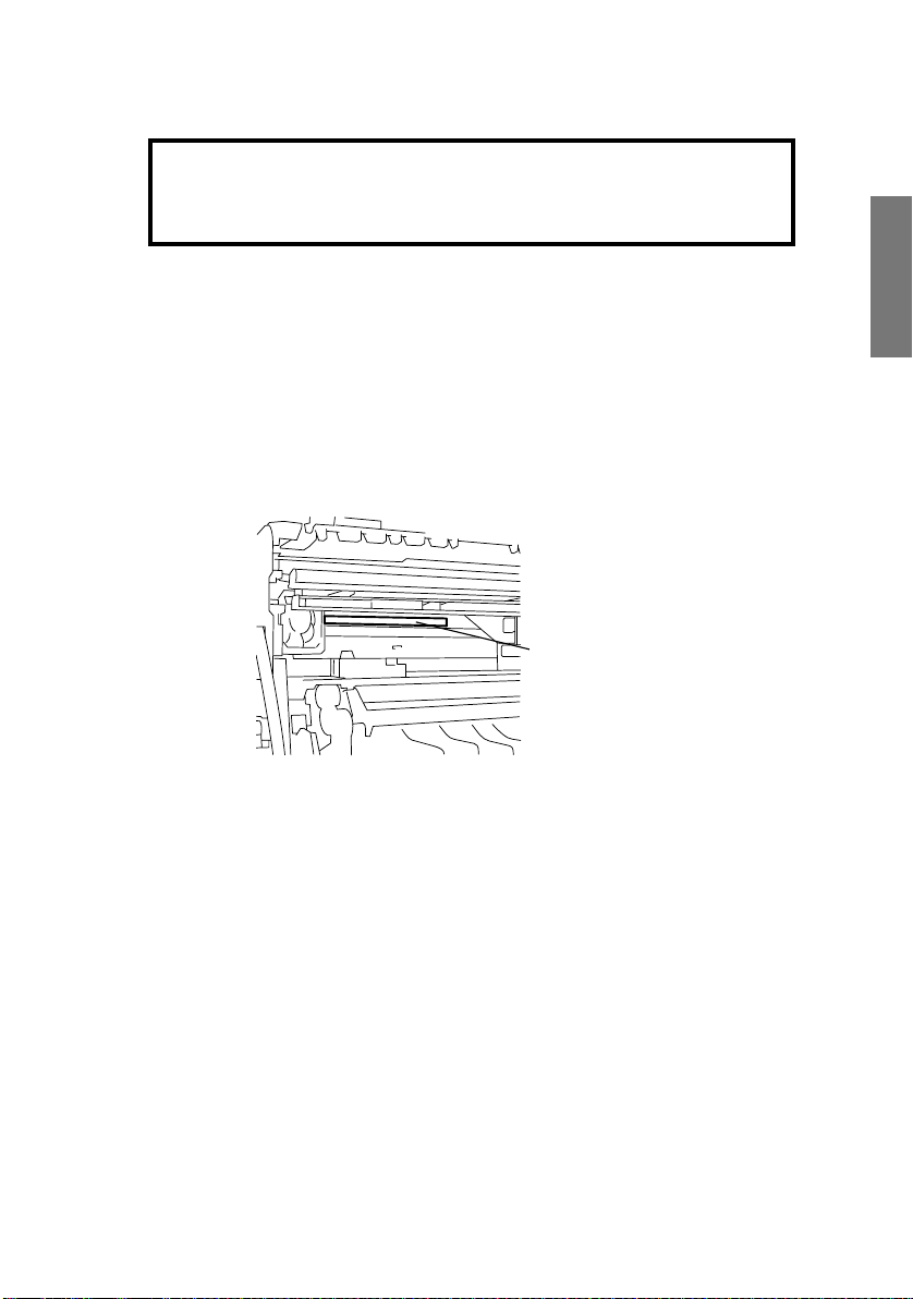
Internal Laser Radiation
MaximumAverageRadiation Power: 19.5 µW (Di251)/27.8 µW (Di351) at laser aperture of
the print head unit
Wavelength: 770-795 nm (Di251)
775-795 nm (Di351)
This productemploys a Class 3b Laser Diode that emits an invisible laser beam.
The Laser Diode and Scanning Polygon Mirror are incorporated in the print head unit.
The print head unit is NOT A FIELD SERVICE ITEM.
Therefore, the print head unit should not be opened under any circumstances.
Laser Aperture of
the Print Head Unit
1166O263AB
This figure shows the view inside the Right
Door with the I maging Unit removed.
CDRH re gulation
This copier is certified as a Class I Laser product under the Radiation Performance Standard according to the Food, Drug and Cosmetic Act of 1990. Compliance is mandatory for
Laser products marketedin t he United Statesand is reported to the Centerfor D evices and
RadiologicalHealth (CDRH) of t he U.S. Food and Drug Administration of the U.S. Departmentof Health and Human Ser vices (DHHS). This means thatthe devicedoes not produce
hazardouslaser radiation.
G-1

The la bel shown to page G-4 indicates compliance with the CDRH regulations and must be
attached to laserproducts marketed in the United States.
CAUTION: Use of controls,adjustments or performance of proceduresother than those
specified in this manual may result in hazardous radiationexposure.
This is a semiconductor laser.The maximum power of the laser diode is 5 mW (Di251)
15 mW (Di351) and the wavelength is 770-795 nm (Di251)/775-795 nm (Di351).
For Europe
CAUTION: Use of controls,adjustments or performance of proceduresother than those
specified in this manual may result in hazardous radiationexposure.
This is a semiconductorlaser. The maximum power of t he laserdiode is 5 mW (Di251)
15 mW (Di351) and the wavelength is 770-795 nm (Di251)/775-795 nm (Di351).
For Denmark
ADVARSEL
Usynlig laserstråling ved åbning, når sikkerhedsafbrydere er ude af funktion.
Undgå udsættelse forstråling.Klasse 1 laser produkt der opfylderIEC60825 sikkerheds
kravene.
Dansk: D ette er en halvlederlaser.Laserdiodens højeste styrke er 5 mW (Di251)
15 mW (Di351) og bølgelængden er 770-795 nm (Di251)/775-795 nm (Di351).
For Finland
LUOKAN 1 LASERLAITE
VAROITUS
Laitteen käyt täminen muulla kuin tässä käyttöohjeessa mainitulla tavalla saattaa altistaa
käyttäjän turvallisuusluokan 1 ylittävälle näkymättömälle lasersäteilylle.
VARO
Avattaessa ja suojalukitus ohitettaessa olet alttiina näkymättomälle lasersäteilylle. Älä
katso säteeseen.
Tämä on puolijohdelaser.Laserdiodin suurin teho on 5 mW (Di251)/15mW (Di351) ja
aallonpituuson 770-795 nm (Di251)/775-795nm (Di351).
For Sweden
KLASS 1 LASER APPARAT
VARNING
Om apparaten används på annat sätt än i denna bruksanvisning s pecificerats, kan
användarenutsättas för osynlig laserstrålning,som överskridergränsen f ör laserklass 1.
G-2

VARNING
Osynlig laserstråining när denna del är öppnad och spärren är urkopplad. Betrakta ej
stråien.
Det här är en halvledarlaser. Den maximala effekten för laserdioden är 5 mW (Di251)
15 mW (Di351) och våglängdenär 770-795 nm (Di251)/775-795 nm (Di351).
For Norway
ADVERSEL
Dersom apparatetbrukes på annen måte enn spesifisert i denne bruksanvisning,kan
brukeren utsettes för unsynlig laserstrålning, som overskrider grensenfor laser klass 1.
Dette en halveder laser.Maksimal effekttill laserdiode er 5 mW (Di251)/15 mW (Di351)
og b
φlgelengde er 770-795 nm (Di251)/775-795 nm (Di351).
Laser Safety Label
A laser safety label is attached to the outside of the copy machine as shown below.
Manufacturer’s
Name Plate
Laser safety label
CLASS 1 LASER PRODUCT
LASER KLASSE
1 PRODUKT
1166O252BA
The Manufacturer’s Name Plate is affixed at the position illustrated ab ove.
Please write down the Model Name and Serial No. of your copier here.
Model:
Serial No.:
G-3
4015O020AB

Label inside copy machine
The following laser safety label will be attached inside the copy machine as shown below.
Please read the following for your own protection.
Caution
Openingthe coverindicatedby the Caution labelmay exposeyouto harmful laserradiation
which could cause damage or loss of eyesight. Do not open the coverwhen the power is
on.
1166O234AA
G-4

ALL Areas
Danger of explosion if battery is incorrectly replaced.
Replace only with the same or equivalent type recommended by the manufacturer.
Dispose of used batteries according to the manufacturer’s instructions.
Germany only
Explosinsgefahr bei unsachgemäßen austauschder batterie.
Ersatz nur durch denselben oder einen vom hersteller empfohlenen ähnlichentyp.
Entsorgunggebrauchter batterien nach angaben des herstellers.
CAUTION
VORSICHT!
Denmark only
Lithiumbatteri - Eksplosionsfare ved fejlagtig håndtering Udskiftning må kun ske med batteri af samme fabrikat og type.
Levér det brugte batteri tilbage t il leverandøren.
Norwayonly
Eksplosjonsfare ved feilaktig skifte av batteri.
Benyttsamme batteritype eller en tilsvarende type anbefalt av apparatfabrikanten.
Brukte batterier kasseres i henhold til fabrikantens instruksjoner.
Sweden only
Explosionsfaravid felaktigt batteribyte.
Använd samma batterityp eller en ekvivalent typ som rekommenderas av
apparattillverkaren.
Kasseraanvänt batteri enligt fabrikantens instruktion.
Finland only
Paristo voi räjähtää, los s e on virheellisesti asennettu.
Vaihda paristo ainoastaan laitevalmistajan suosittelemaantyyppiin.
Hävitä Käytetty paristo valmistajan ohjeiden mukaisesti.
ALL Areas
“Replace only with the same or equivalenttype recommended by the manufacturer.
Dispose of used IC Package accordingto the manufacturer’s instructions.”
ADVARSEL!
ADVARSEL
VARNING
VAROlTUS
CAUTION
Germany only
”Austausch nur durch denselben oder einen vom Hersteller empfohlenen,gleichwertigen
typ.Entsorgung gebrauchter Batterien nach A ngaben des Herstellers.
VORSICHT!
G-5

2. SPECIFICATION
TYPE
ORIGINAL SCANNING SYSTEM
PHOTOCONDUCTOR
COPYING SYSTEM
RESOLUTION
PAPER FEEDING SYSTEM
EXPOSURESYSTEM
DEVELOPING SYSTEM
CHARGING SYSTEM
IMAGE TRANSFER SYSTEM
PAPER SEPARATING SYSTEM
FUSING SYSTEM
PAPER DISCHARGING SYSTEM
MAX. ORIGINAL SIZE
COPY PAPER TYPE
PaperSource 1st Drawer Manual Feed Tray
Plain paper (60 to 90 g/m
Transparencies ❍❍
Type
Dimensions
❍: Reliably fed
Thickpaper (91 to 157 g/m
Postcards (190 g/m
Recycled paper ❍❍
Maximum (Width
Minimum (Width
:
Console/Desktop Type
:
CCD Line Sensor
:
Organic Photoconductor
:
Electrostatic Dry PowderedImage Transfer to Plain
Paperwith a Laser
:
600 dpi
:
3-way system
Manual Feed Tray...Single
1st Drawer...............250 Sheets (Plain paper)
2nd Drawer.............500 Sheets (Plain paper)
:
Mirror Scanning, Slit Exposure
:
MT-HG System
:
Comb Electrode (1) DC Negative Corona with
Scorotron System
Roller Image Transfer
:
PaperSeparator Fingersand Charge Neutralizing
:
Plate
Heat Roller
:
Charge Neutralizing Brush
:
A3L, 11”
:
× Length) 297 × 432 mm 297 × 432 mm
× Length) 90 × 140 mm 90 × 140 mm
× 17”L
2
)
2
)
2
)
50 Sheets (Special paper)
35 CPM/25 CPM: Standard
❍❍
❍❍
❍❍
MULTIPLE COPIES
WARMING-UP TIME
FIRST COPY TIME
:
35CPM(1to999),25CPM(1to99)
:
35 CPM (70 sec. or less)
25 CPM (60 sec. or less)
A4C, 1st Drawer, full size mode
:
35 CPM (4.6 sec.), 25 CPM (5.8 sec.)
G-6
CONTINUOUS COPY SPEED (copies/min)
-Metric- -Inch-
Size Speed Size Speed
A3L
B4L
A4L
A4C
B5L
B5C
ZOOM RATIOS
Fixed
Variable 25 % to 400 % (in 0.1 % increments)
LENS
EXPOSURE LAMP
FUSING TEMPERATURE
20
23
27
35
30
40
Full Size
Enlargement
Reduction
Through Lens (F = 4.0, f = 62 mm)
:
FluorescentLamp
:
190 °C
:
11
× 17L
8-1/2
× 14L
8-1/2
× 11L
8-1/2
× 11C
- Metric - - Inch -
× 1.000 × 1.000
× 2.000
× 1.414
× 1.224
× 1.154
× 0.866
× 0.816
× 0.707
× 0.500
20
23
28
35
× 2.000
× 1.545
× 1.294
× 1.214
× 0.785
× 0.733
× 0.647
× 0.500
POWER/CURRENT CONSUMPTION (copier only)
ExposureLamp
(Rating)
24 V
20 W
POWER REQUIREMENTS : 230 V, 50/60 Hz
ENVIRONMENTAL CONDITIONS
Temperature 10 to 32 °C with a fluctuationof 10 °C or less per hour
Humidity 15 to 85 % RH with a fluctuation of 10 % RH or less per hour
Ambient Illumination 3,000 lux or less
Levelness 1° (1.75 mm/100 mm)
Fusing Roller
Heater Lamp
(Rating)
35 CPM: 800 W
25 CPM: 800 W
Max. Power
Consumption
(full system)
230 V: 1450 W
Max. Current
Consumption
(full system)
Metric area
35 CPM/25 CPM: 6 A
Inch area
35 CPM/25 CPM: 11.5 A
G-7

COPIER DIMENSIONS
COPIER WEIGHT
::Metric area
35 CPM: W...632 mm, D...707mm, H...647 mm
25 CPM: W...594 mm, D...707mm, H...647 mm
Inch area
35 CPM: W...25, D. ..27-3/4, H...25-1/2
25 CPM: W...23-1/2, D...27-3/4,H...25-1/2
Metric area
35 CPM: 60.5 kg, 25 CPM: 58.7 kg
Inch area
35 CPM: 133-1/2 lb,25 CPM: 129-1/2 lb
G-8

3. PRECAUTIONS FOR INSTALLATION
3-1. Installation Site
To ensure safety and utmost performanceof the copier,the copiershould NOT be used in a
place:
• Whereit will be s ubjected to extremely high or low t emperature or humidity.
• Whereit will be s ubjected to sudden fluctuations in either temperature or humidity.
• Which is exposed to direct sunlight.
• Which is in the direct air stream of an air conditioner, heater, or ventilator.
• Which has poor ventilation or is dusty.
• Which does not have a stable, level floor or where it will receive undue vibration.
• Which is near any kind of heating device.
• Whic h is near volatile flammables(thinner, gasoline, etc.).
• Where it may be splashed with water.
• Whic h puts the operator in the direct stream of exhaustfrom the copier.
• Where ammonia gas might be generated.
3-2. Power Source
• If any other electrical equipment is sourced from the same power outlet, make sure that
the capacityof the outlet is not exceeded.
• Use a power source with little voltage fluctuation.
• Neverconnect by means of a multiple socket any other appliances or machines to the
outletbeingusedforthecopier.
• Ensure that the copier does not ride on the power cord or communication cable of other
electricalequipment, and that it does not become wedged into or underneath the mechanism.
• Make the following checks at frequent intervals:
✽ Is the power plug abnormally hot?
✽ Are there any cracks or scrapes in the cord?
✽ Ha s the power plug been inserted f ully into the outlet?
✽ Does something, including the copier itself,ride on the power cord?
Use an outlet with a capacity of 15 A or more. 220 to 240 V, 10 A or more.
3-3. Grounding
• Always ground the copier to prevent receivingelectrical shocks in the case of electrical
leakage.
• Connectthe groundwire to the ground terminalof the outlet or a groundingcontactwhich
complies with the local electrical standards.
• Neverconnect the ground wire to a gas pipe, the ground wire for a telephone, lightning
arrester, or a water pipe for fear of fire and electrical shock.
G-9

4. PRECAUTIONS FOR USE
4-1. To ensure that the copier is used in an optimum condition
• Neverplace a heavy object on the copier or subject the copier to shocks.
• Insert the power plug all the way into the outlet.
• Do not attemptto removeany panel or cover which is secured while the copier is making
copies.
• Do not turn OFF the copier while it is making copies.
• Provide good ventilation when making a large number of copies c ontinuously.
• Never use flammable sprays near the copier.
• If the copier becomes inordinately hot or produces abnormal noise, turn it OFF and
unplug it.
• DonotturnONthepowerswitchatthesametimewhenyouplugthepowercordintothe
outlet.
• When unpluggingthe power cord, do not pull on the cord; hold the plug and pull it out.
• Do not bring any magnetizedobject near the copier.
• Do not place a vase or vessel containing water on the copier.
• Besure to turn OFF the power switchat the end of the workday or upon power failure.
• Use care not to drop paper clips,staples, or o ther small pieces of metal into the copier.
4-2. Operating Environment
The operating environmentalrequirements of the copier are as follows.
• Temperature:10to32°C
• Humidity:15 to 85 % RH
• Rate of temperature change: 10 °C/h
• Rate of humidity change: 10 % RH/h
4-3. Power Requirements
The power source voltage requirementsare as follows.
• Voltage f luctuation: AC 220 to 240 V ±10 %
• Frequency fluctuation: 50/60 Hz ±0.3 %
(copying performance assured)
+10 %/-15 % (paper feeding performanceassured)
4-4. Note
• It is prohibited to copy paper and hard currencies,government securities, and municipal
bonds (even when they are stamped as “Sample”).
• For fear of infringement of copyright, it is also prohibited to copy copyrightedworks,
including books, music, works of art, maps, drawings,motion pictures,and photos except
whenthecopyistobeusedonlypersonally.
G-10

5. HANDLING OF CONSUMABLES
Before using any consumables, a lways read the label on its container carefully.
• Paper can be easily damaged by dampness.To preventabsorption of moisture,store
paper, which has been removed from its wrapper but not loaded in the drawer, in a
sealed plastic bag in a cool, dark place.
• Keep consumables out of the reach of children.
• Do not touch the PC Dr um with bare hands.
• The same sized paper is of two kinds, short grain and long grain. Short grain paper
should only be fed through the copier crosswise, long grain paper should only be fed
lengthwise.
• If your hands become soiled with toner, wash them with soap and water.
• Do not throwaway any used consumables(PC Drum, starter,toner,etc.). They are to be
collected.
• Do not burn, bury in the ground, or throw into the water any consumables (PC Drum,
starter, toner, etc.).
• Donot store consumables in a p lacewhich:
✽ Is hot and humid.
✽ Is subject to direct sunlight.
✽ Hasanopenflamenearby.
G-11

6. OTHER PRECAUTIONS
Use the following precautions when performing service jobs for a copier that uses a laser.
• When a service job needs to be performed in the laser beam path, such aswhen working
around the printerhead or PC Drum, be sure first to unplug the power cord of the copier
from the outlet.
• If the job requires that the power cord be left plugged in, observe the following precautions.
1. Take off your watch, ring and any other reflective object and wear laser protective gog-
gles.
2. Keep users away from t he job site.
3. Do not bring a highly reflectivetool into the laser beam path during the service job.
G-12

7. SYSTEM OPTIONS
1
2
3
13
18
4015O218AA
1166O011AA
1166O012AA
14, 15
1166O014AA 1166O007AA
1166O008AA
19
1145M035AA
17
4002O102AA
4015O025AB
4015O028AB
16
4015O027AA
4002O099AA
4015O029AA
1166O190AA
11
12
4
5
6, 7
8
9
10
1. Duplexing Document Feeder AFR-17
2. Automatic Document Feeder AF-9
3. Original Cover Kit OC-3
4. Plug-In Counter
5. Duplex Unit AD-15 (35 CPM: Standard)
6. Paper Feed Unit PF-118
7. Paper Feed Unit PF-119
(35CPM/25CPM:Standard)
8. Large Capacity Cabinet PF-117
9. Copy Table
G-13
1166O191AB
10.Copy Desk
11. Pr inter Controller Pi3502
12.8MB/16MB/32MB Memory
13.Data TerminalDT-103
14.Finisher FN-109
15.Finisher FN-110
16.Job Tray JS-201
17.Shift TrayOT-102
18.Option TrayJS-100
19. Mailbin Finisher FN-5 04

MECHANICAL/
ELECTRICAL

CONTENTS
1. CROSS-SECTIONAL VIEW ............................................................................M-1
2. COPYING PROCESS ......................................................................................M-2
3. DRIVE SYSTEM ..............................................................................................M-4
4. OPERATING SEQUENCE ..............................................................................M-5
5. CPUOVERRUN MONIT OR FUNCTION .........................................................M-6
5-1. Processing Performed during Watchdog Function ..................................M-6
6. IMAGE STABILIZATION SYSTEM ..................................................................M-7
7. IMAGING CARTRIDGE (I/C) ...........................................................................M-8
7-1. I/C Drive Mechanism ...............................................................................M-9
7-2. Identification and Life of I/C .....................................................................M-9
8. P C DRUM ........................................................................................................M-10
8-1. Grounding of the PC Drum ......................................................................M-10
9. DRUM CHARGING ..........................................................................................M-11
(1) Ozone Fan .......................................................................................M-12
10. IR SECTION ....................................................................................................M-13
10-1.Construction of the Exposure Section .....................................................M-14
10-2.Image Processing Flow ...........................................................................M-15
10-3.Scanner and 2nd/3rd Mirrors Carriage Moving Mechanism ....................M-16
(1) Scanner Moving Mechanism ........................................................... M-16
(2) 2nd/3rd Mirrors Carriage Moving Mechanism .................................M-16
11. ORIGINAL SIZE DETECTING SYSTEM .........................................................M-17
11-1.Original Size Detecting Operation ...........................................................M-18
11-2.Original Size Detection ............................................................................M-18
11-3.Original Size Detection Timing ................................................................M-19
12. PH SECTION ...................................................................................................M-20
12-1.Laser Emission Timing ............................................................................M-21
13. DEVELOPING UNIT ........................................................................................M-22
13-1.Sleeve/Magnet Roller ..............................................................................M-23
13-2.Developing Bias .......................................................................................M-23
13-3.ATDC Sensor ..........................................................................................M-24
(1) ATDC Sensor Automatic Adjustment ..............................................M-24
(2) Toner Replenishing Control .............................................................M-24
(3) Toner Empty Control (T/C Recovery Mode) ....................................M-25
13-4.Toner Bottle Home Position Detection Mechanism .................................M-26
13-5.Toner Bottle Vibration Mechanism ..........................................................M-26
13-6.Main Hopper Toner Replenishing Mechanism ........................................M-27
13-7.Sub Hopper Toner Replenishing Mechanism ..........................................M-28
13-8.Sub Hopper Toner Empty Detection Control ...........................................M-28
14. PAPER TAKE-UP/FEED SECTION ................................................................ M-29
14-1.1st Drawer-in-Position Detection .............................................................M-29
14-2.1st Drawer Paper Empty Detection .........................................................M-30
14-3.1st Drawer Paper Near-Empty Detection ................................................M-30
14-4.1st Drawer Paper Lifting Plate .................................................................M-31
14-5.1st Drawer Paper Size Detection ............................................................M-31
(1) Paper Size Table According to Sensor/Switch Conditions ..............M-32
14-6.Drawer Paper Take-Up Mechanism ........................................................M-33
i

(1) Paper Separating Mechanism .........................................................M-33
14-7.Drawer Paper Take-Up Control ...............................................................M-34
(1) Paper Take-Up Roll .........................................................................M-34
(2) Paper Take-Up Retry Control ..........................................................M-34
(3) Paper Take-Up Interval Control .......................................................M-34
(4) Double Feed Paper Take-Up Control (35-cpm copier only) ............M-35
15. MANUAL BYPASS TRAY ................................................................................M-36
15-1.Manual Bypass Paper Take-Up Control ..................................................M-36
15-2.Manual Bypass Paper Empty Detection ..................................................M-36
16. SYNCHRONIZING ROLLERS .........................................................................M-37
16-1.Paper Dust Remover ...............................................................................M-37
16-2.Synchronizing Roller Drive Mechanism ...................................................M-38
17. IMAGE TRANSFER AND PAPER SEPARATION ...........................................M-39
17-1.PC Drum Paper Separator Fingers .........................................................M-39
18. PC DRUM CLEANING ..................................................................................... M-40
19. ERASE LAMP ..................................................................................................M-41
20. FUSING UNIT ..................................................................................................M-42
20-1.Fusing Unit Drive Mechanism ..................................................................M-43
20-2.Fusing Temperature Control ....................................................................M-44
(1) Temperature Control Table during Standby State and Copy Cycle M-44
20-3.CPM Control ............................................................................................M-44
21. PAPER EXIT UNIT ..........................................................................................M-45
22. OTHER UNITS AND MECHANISMS ..............................................................M-46
22-1.Memory Backup .......................................................................................M-46
22-2.Flash Memory ..........................................................................................M-46
22-3.Interior Cooling Mechanism .....................................................................M-47
(1) I/C Cooling Mechanism ...................................................................M-47
(2) Fusing Section Cooling Mechanism ................................................M-48
(3) Power Supply Section Cooling Mechanism .....................................M-49
ii

1. CROSS-SECTIONAL VIEW
2
1
18
3
4
5
67
8
9
10
11
12
1. 2nd Mirror
2. 3rd Mirror
3. Exposure Lamp
4. 1st Mirror
5. Lens
6. CCD Unit
7. Paper Exit Roller
8. Fusing Transport Roller
9. Right Fusing Roller
17
16
10.Image TransferRoller
11.Synchronizing Roller
12.Manual Bypass Tray
13.Manual Feed Paper Take-Up Roll
14.Paper SeparatorPad
15.Paper Take-Up Roll
16.Imaging Cartridge I/C
17.PH Unit
18.Left Fusing Roller
15
14
M-1
13
4011M001AA
2. COPYING PROCESS
13. Fusing
10. Paper Separation
9. Image Transfer
8. Manual Bypass
3. PhotoelectricConversion Section
2. Drum Charging
4. MFB2 Board
5. Laser Exposure
14. Paper Exit
11. Cleaning
12. Erase
1. PC Drum
6. Development
7. Paper Feed
1. PC Drum
• Changes the image of the original projected onto the surface of the drum to a corresponding electrostatic latent image.
2. Drum Charging
• Generatesa negative DC charged layer on the surfaceof the PC Drum.
3. Photoelectric Conversion Section
• The CCD converts the light reflected off the original to a corresponding electrical signal
and outputs it to the IR image processing section.
4. MFB2 Board
• Convertsthe electrical signalto a corresponding 8-bit digitalimage signal, makesvarious
corrections,and outputs the results to t he memory.
• Compressesand stores in memory the digitalimage signal,and then outputsit to the PH
image processing section.
• After going through necessary corrections, the digital image signal is convertedto a correspondinganalog signal, based on which the intensity of the laser light is controlled.
5. Laser Exposure
• Alaser beam strikes the surface of the PC Drum, creating an electrostaticlatent image.
6. Development
• Negatively charged toneradheres to the latentimage onthe PC Drum surface,creatinga
visible image.
• AC/DC negative bias voltages are applied to the Sleeve/Magnet Roller, thereby preventing toner from sticking to the background.
• Toner scraped off by the cleaningmechanism is recycled.
7. Paper Feed
• Feeds sheets of paper from the appropriate paper source.
8. Manual Bypass
• Feeds sheets of paper from the Manual Bypass Tray.
9. Image Transfer
• Apositive charge is applied to the Image Transfer Roller to transfer the visible image on
the surfaceof the PC Drum onto the paper.
10.Paper Separation
• The PC Drum Separator Fingers remove paper from the surface of the PC Drum.
M-2

11. Cleaning
• Residual toner is scraped off the surface of the PC Drum.
• The toner is then recycled back to the Developing Unit.
12. Erase
• The PC Drum is exposed to light, which effectively neutralize any residual charge on the
surface of the PC Drum.
13. Fusing
• Heat and pressure applied by the Right and Left FusingRollers fuse toner on the paper.
14. Paper Exit
• Feeds paper out of the copier onto the Exit Tray.
M-3
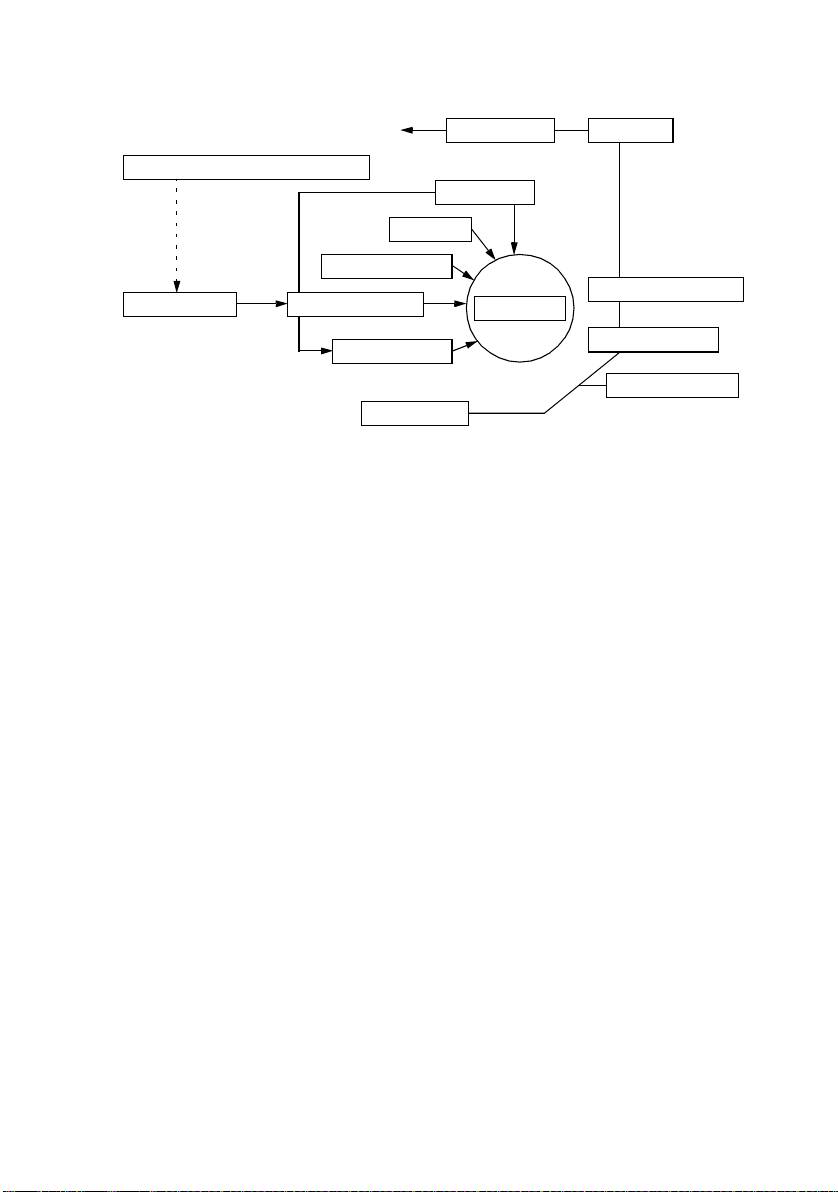
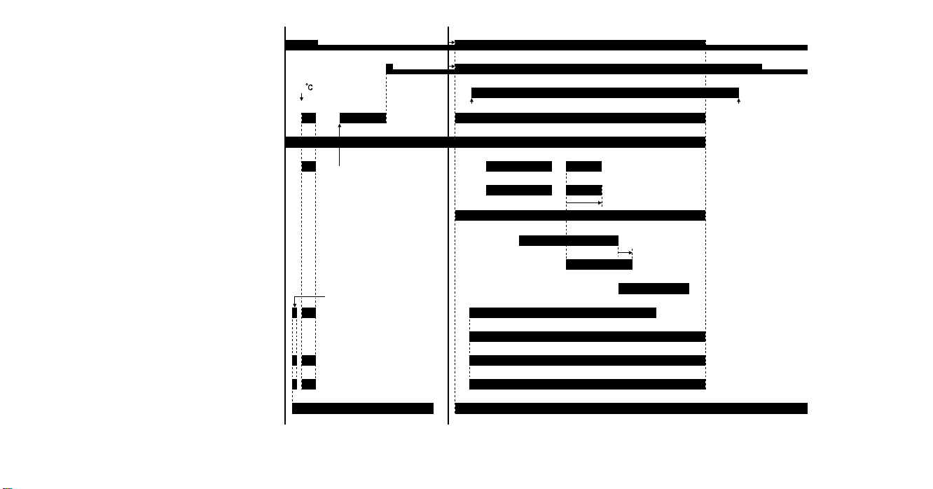
3. DRIVE SYSTEM
1
1. Scanner Motor M10
2. Main Motor M2
3. I/C Motor M1
M-4
32
4011M002AA
Power Switch ON Start key ON
Power Unit Cooling Fan Motor M4
Cooling Fan Motor M3
Ozone Fan Motor M8
Main Motor M2
Fusing Roller Heater Lamp H1
Full speed
170
Predrive
Half speed
Full speed
Fusing predrive
Half speed
Full speed
Full speed
*1 *2
Half speed
Half speed
4. OPERATING SEQUENCE
FrameMaker Ver5.5E(PC) Di251/Di351 MECHANICAL/ELECTRICAL
.05.03.01
M-5
Manual Feed Paper Take-Up Clutch CL2
1st Drawer Paper Take-Up Solenoid SL1
Polygon Motor M5
Synchronizing Roller Sensor PC2
Synchronizing Clutch CL1
Paper Exit Sensor PC3
I/C Motor M1
Laser
Drum Charge Bias
Image Transfer Bias
4011M028CA
Developing Bias
Warm-up completed
Agitation predrive
*1: When the Main Motor or I/C Motor remains energized for a continuous 300-ms period.
*2: When the Main Motor and I/C Motor remain deenergized for a continuous 10-s period.

5. CPU OVERRUN MONITOR FUNCTION
• The CPU overrun monitor function (watchdog function) is a self-monitoringfunction that
determines whether any of the CPUs mounted on the copier overruns.
• If this functiondetects that a CPU overruns,the copier automaticallyresets the CPU,
restarting the logic circuit and mechanism.
• The copier CPU not only performs the self-monitoring function, but also checks the communicationstatus with the option’s CPU.
5-1. Processing Performed during Watchdog Function
The following operations are performedwhen a CPU operates erratically.
If a copier CPU overruns:
• All CPUs includingthose of the options are reset and a restart sequence is performed.
• Ifthe overrun occurs during a copy cycle, the copier triesto feed all sheets of paper out of
itselfbefore resetting theCPU. (Any sheet of paper that could not be fed out of the copier
is detected as a sheet of paper left when the restart sequence is later carried out.)
If an erratic operation is detected in communications with the option’s CPU:
• The copier turns OFF and O N the option’s relay and performs a restart sequence of the
option.
• If the overrun occurs during a copy cycle, the copier stops the paper take-up operation,
feedsall sheets of paperout of itself,and then performsa restart sequence of the option.
M-6

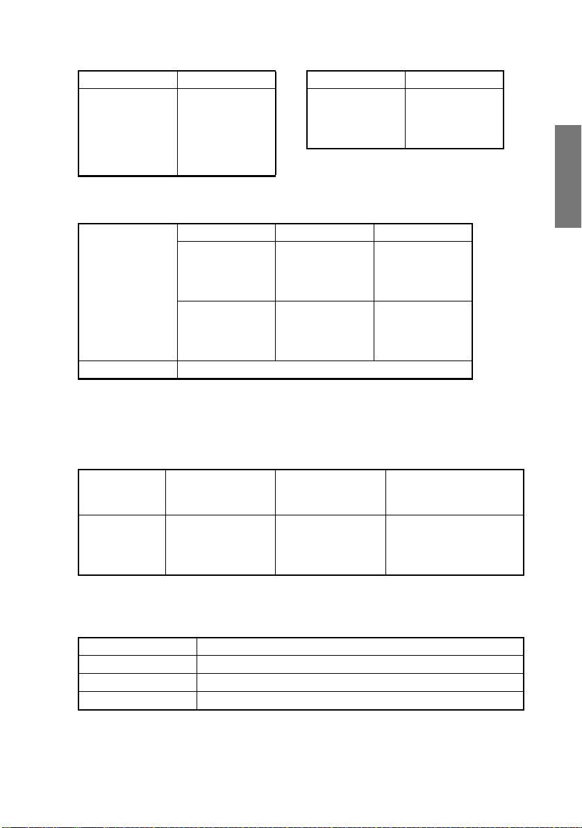
6. IMAGE STABILIZATION SYSTEM
• Thefollowing image stabilization controls are provided to ensure stabilized copy image.
Item Purpose Control
PC Drum temperature
correction
PC Drum deterioration
correction
Grid Voltage: Vg
To compensate for any change
in ID due to changing PC Dr um
temperatures.
To compensate for degraded
sensitivity caused by a deteriorating PC Drum.
PC Drum
Sleeve/
Magnet Roller
Developing Bias: Vb
I/CThermistor is used to detect
temperatureand, according to
the detectedtemperature,Vg/
Vb is corrected.
Vg is correctedaccording to the
period of time during which the
PC Drum has turned.
PC Drum Charge Corona
I/C Thermistor TH2
PC Drum Revolution
Counter
M-7
CPU
1171M028AA

7. IMAGING CARTRIDGE (I/C)
• This copier employs an Imaging Cartridge (“I/C” in this manual).
• The I/C contains a PC Drum, DevelopingUnit, PC Drum Charge Corona, and a Cleaning
Unit as one unit.
Toner Supply Port
1171M002AA
1171M003AA
ATDC Sensor UN2
M-8
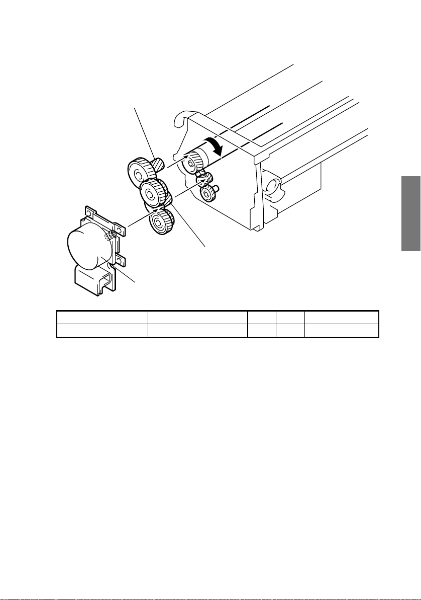
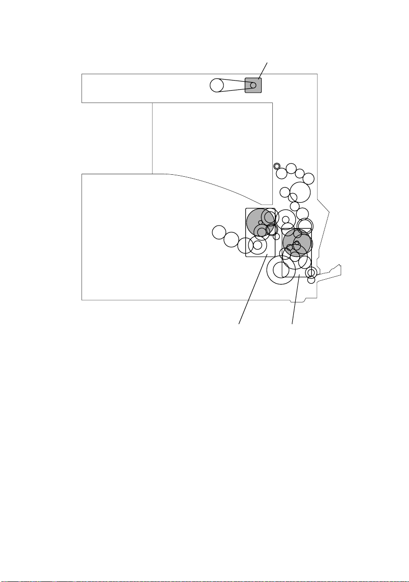
7-1. I/C Drive Mechanism
• Drive from the I/C Motor is transmitted via a gear train to the PC Drum and Hopper.
PC Drum Drive Gear
Hopper Drive Gear
I/C Motor M1
4011M021AA
ElectricalComponent Control Signal ON OFF Wiring Diagram
M1 PJ5A-3 L H 5-G
7-2. Identification and Life of I/C
• When the Start key is pressed or the Side Cover is opened and closed, the copier determines whether the I/C is new or one which has been used previously.
• The copier monitors the I/C life by storing in memory the period of time during which the
PC Drum has turned. The data is c leared when a new I/C is installed in the copier.
M-9
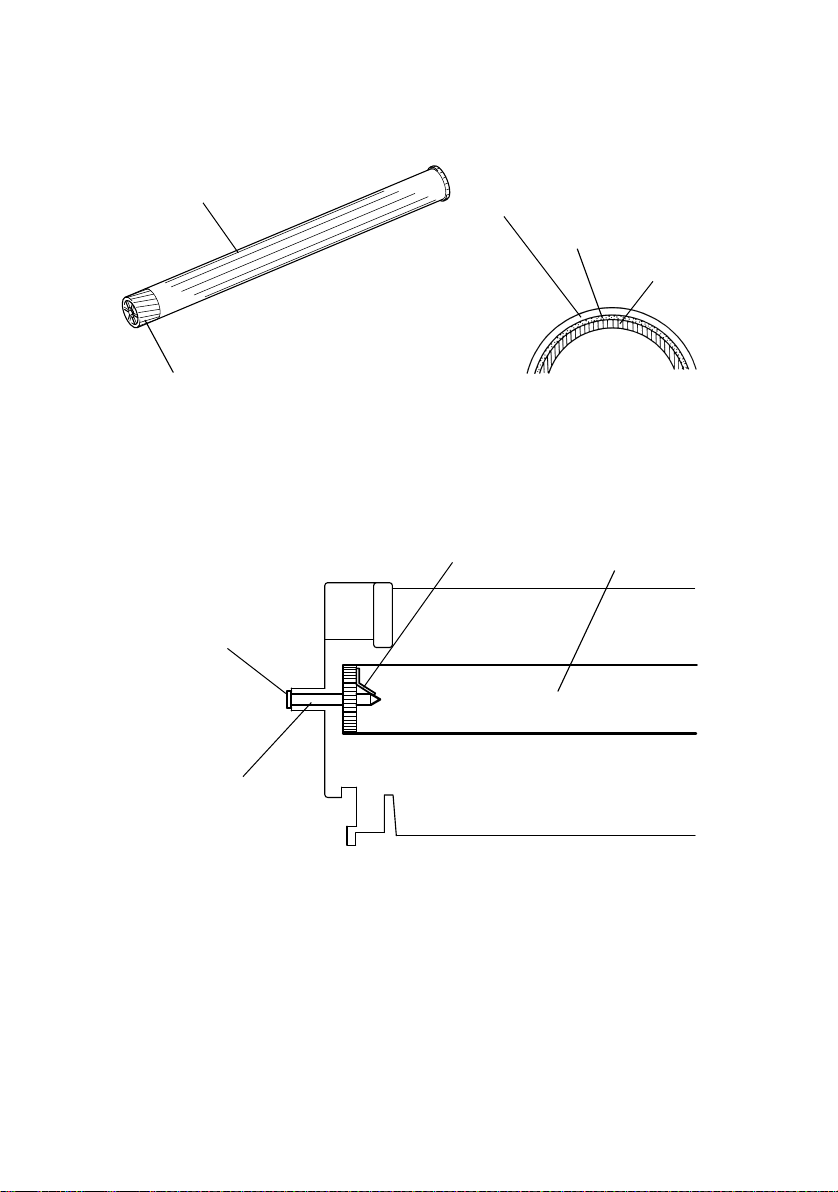
8. PC DRUM
• The PCDrum consists of an aluminum base coated with a charge generation layer and a
charge transport layer.
PC Drum
1167M007AA
Gear
(PC Drum Cross-Section)
Charge Transport Layer
Charge GenerationLayer
AluminumBase
1139M007AA
8-1. Grounding of the PC Drum
• The potentialof the areas on the surface of the PC Drum exposedto the laser light is
grounded to the frame.
Ground Point
Ground Plate
PC Drum
Shaft
1171M005AA
M-10
 Loading...