

Konica Minolta 8050, 8150, CF5001, bizhub Pro C500 Service Manual

SERVICE MANUAL
8050/CF5001
C500
8150
FIELD SERVICE
2004. 12
Ver. 3 . 0

SAFETY AND IMPORTANT WARNING ITEMS
SAFETY AND IMPORTANT WARNING ITEMS
Read carefully the Safety and Important Warning Items described below to understand them before doing ser-
vice work.
IMPORTANT NOTICE
Because of possible hazards to an inexperienced person servicing this copier as well as the risk of damage to
the copier, Konica Minolta Business Technologies, INC. (hereafter called the KMBT) strongly recommends that
all servicing be performed only by KMBT-trained service technicians.
Changes may have been made to this copier to improve its performance after this Service Manual was printed.
Accordingly, KMBT does not warrant, either explicitly or implicitly, that the information contained in this Service
Manual is complete and accurate.
The user of this Service Manual must assume all risks of personal injury and/or damage to the copier while ser-
vicing the copier for which this Service Manual is intended.
Therefore, this Service Manual must be carefully read before doing service work both in the course of technical
training and even after that, for performing maintenance and control of the copier properly.
Keep this Service Manual also for future service.
DESCRIPTION ITEMS FOR DANGER, WARNING AND
CAUTION
In this Service Manual, each of three expressions “ DANGER”, “ WARNING”, and “ CAUTION” is defined
as follows together with a symbol mark to be used in a limited meaning.
When servicing the copier, the relevant works (disassembling, reassembling, adjustment, repair, maintenance,
etc.) need to be conducted with utmost care.
DANGER
WARNING
CAUTION
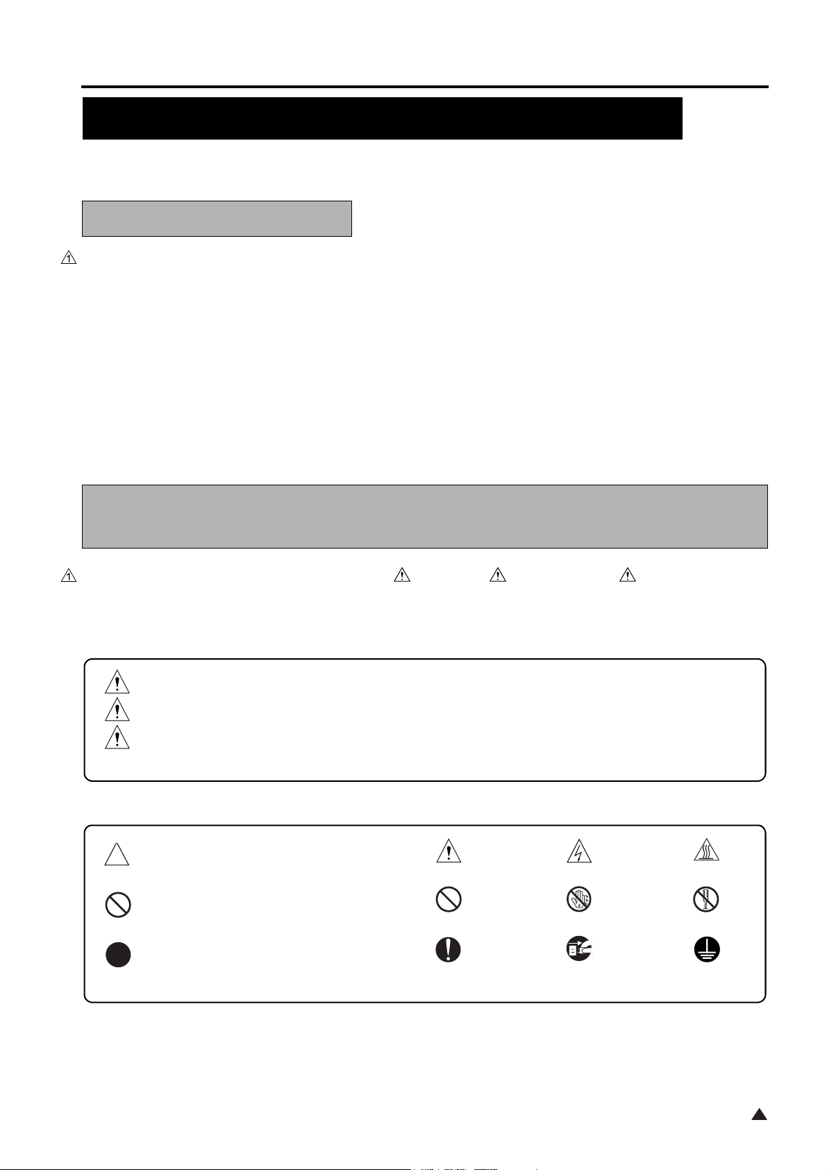
Symbols used for safety and important warning items are defined as follows:
:Precaution when using the copier.
:Action having a high possibility of suffering death or serious injury
:Action having a possibility of suffering death or serious injury
:Action having a possibility of suffering a slight wound, medium trouble, and
property damage
General precaution Electric hazard High temperature
:Prohibition when using the copier.
:Direction when using the copier.
General prohibition Do not touch with wet hand Do not disassemble
General instruction
S-1
Unplug
Ground/Earth
1
SAFETY AND IMPORTANT WARNING ITEMS
SAFETY WARNINGS
1. MODIFICATIONS NOT AUTHORIZED BY
KONICA MINOLTA BUSINESS TECHNOLOGIES, INC.
Konica Minolta brand copiers are renowned for their high reliability. This reliability is achieved through high-quality design
and a solid service network.
Copier design is a highly complicated and delicate process where numerous mechanical, physical, and electrical aspects
have to be taken into consideration, with the aim of arriving at proper tolerances and safety factors. For this reason, unau-
thorized modifications involve a high risk of degradation in performance and safety. Such modifications are therefore
strictly prohibited. the points listed below are not exhaustive, but they illustrate the reasoning behind this policy.
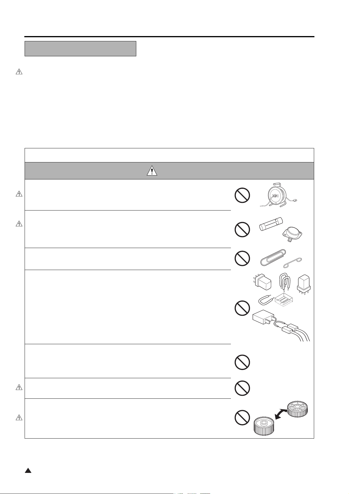
PROHIBITED ACTIONS
DANGER
• Using any cables or power cord not specified by KMBT.
• Using any fuse or thermostat not specified by KMBT. Safety will not be
assured, leading to a risk of fire and injury.
• Disabling fuse functions or bridging fuse terminals with wire, metal clips, sol-
der or similar object.
• Disabling relay functions (such as wedging paper between relay contacts)
• Disabling safety functions (interlocks, safety circuits, etc.) Safety will not be
assured, leading to a risk of fire and injury.
• Making any modification to the copier unless instructed by KMBT
• Using parts not specified by KMBT
1
S-2
SAFETY AND IMPORTANT WARNING ITEMS
2. CHECKPOINTS WHEN PERFORMING ON-SITE SERVICE
Konica Minolta brand copiers are extensively tested before shipping, to ensure that all applicable safety standards are met,
in order to protect the customer and customer engineer (hereafter called the CE) from the risk of injury. However, in daily
use, any electrical equipment may be subject to parts wear and eventual failure. In order to maintain safety and reliability,
the CE must perform regular safety checks.
2.1 Power Supply
Connection to Power Supply
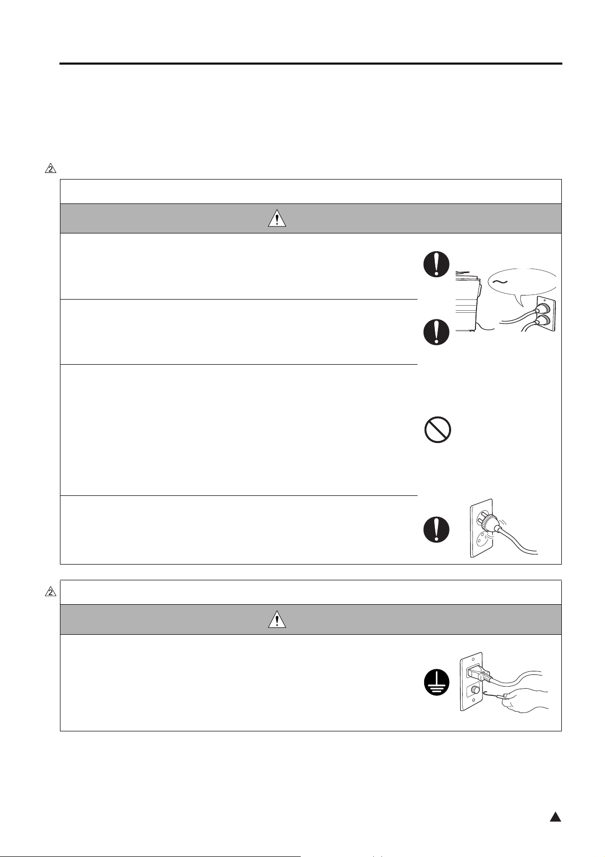
WARNING
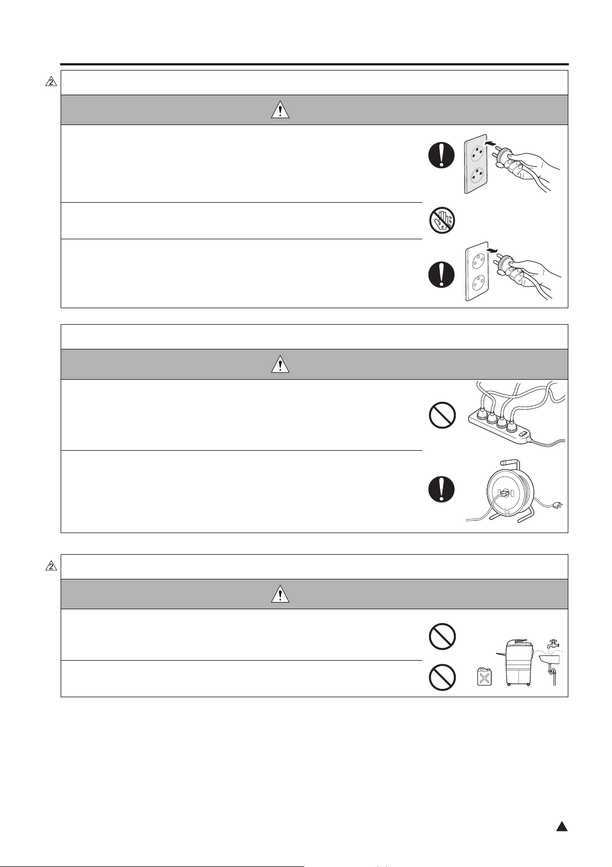
• Check that mains voltage is as specified. Plug the power cord into the dedi-
cated wall outlet with a capacity greater than the maximum power consump-
tion.
If excessive current flows in the wall outlet, fire may result.
• If two or more power cords can be plugged into the wall outlet, the total load
must not exceed the rating of the wall outlet.
If excessive current flows in the wall outlet, fire may result.
kw
• Connect power plug directly into wall outlet having same configuration as the
plug.
Use of an adapter leads to the product connecting to inadequate power
supply (voltage, current capacity, grounding), and may result in fire or elec-
tric shock.
If proper wall outlet is not available, advice the customer to contact quali-
fied electrician for the installation.
• Make sure the power cord is plugged in the wall outlet securely.
Contact problems may lead to increased resistance, overheating, and the
risk of fire.
Ground Lead
WARNING
• Check whether the copier is grounded properly.
If current leakage occurs in an ungrounded copier, you may suffer electric
shock while operating the copier. Connect the ground lead to one of the
following points:
a. Ground terminal of wall outlet
b. Ground terminal for which Class D work has been done
S-3
2
SAFETY AND IMPORTANT WARNING ITEMS
Ground Lead
WARNING
• Pay attention to the point to which the ground lead is connected.
Connecting the ground lead to an improper point such as the points listed
below results in a risk of explosion and electric shock:
a. Gas pipe (A risk of explosion or fire exists.)
b. Lightning rod (A risk of electric shock or fire exists.)
c. Telephone line ground (A risk of electric shock or fire exists in the case
of lightning.)
d. Water pipe or faucet (It may include a plastic portion.)
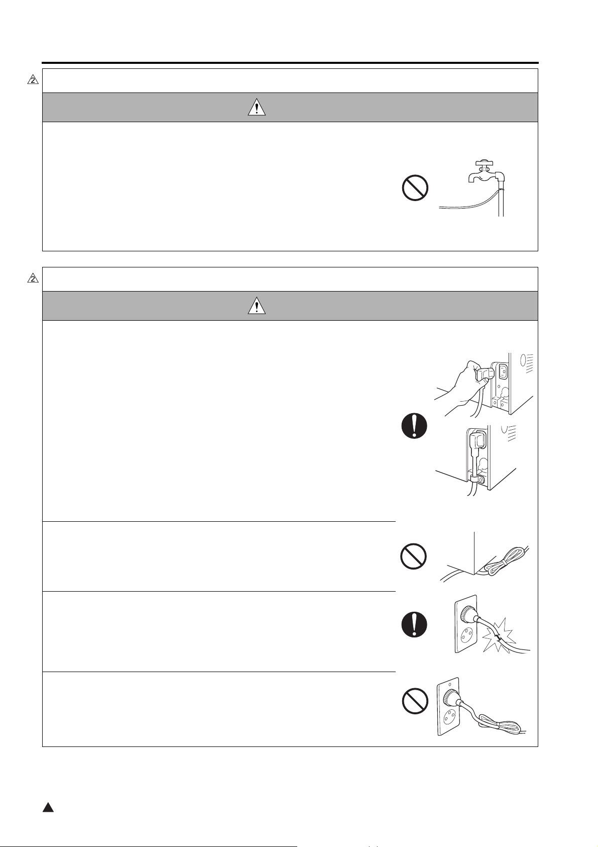
Power Plug and Cord
WARNING
• For the products that use the power cord set (inlet type), be sure to follow the
directions given below.
When securing measure is provided, secure the cord with the fixture prop-
erly.
a. Be sure to check to see if the power cord is securely inserted into the
main body side inlet.
b. When the fixing of the cord is indicated in the installation instructions,
be sure to fix it securely by using the fixing materials provided in the
same package.
c. When the power cord is damaged with its sheath broken, be sure to
replace it with the specified power cord set.
When the power cord is not securely inserted, an abnormal heat may gen-
erates due to a poor contact of the cord, thus resulting in a fire.
• Check whether the power cord is not stepped on or pinched by a table and
so on.
Overheating may occur there, leading to a risk of fire.
• Check whether the power cord is damaged. Check whether the sheath is
damaged.
If the power plug, cord, or sheath is damaged, replace with a new power
cord (with plugs on both ends) specified by KMBT. Using the damaged
power cord may result in fire or electric shock.
• Do not bundle or tie the power cord.
Overheating may occur there, leading to a risk of fire.
2
S-4
SAFETY AND IMPORTANT WARNING ITEMS
Power Plug and Cord
WARNING
• Check whether dust is collected around the power plug and wall outlet.
Using the power plug and wall outlet without removing dust may result in
fire.
• Do not insert the power plug into the wall outlet with a wet hand.
The risk of electric shock exists.
• When unplugging the power cord, grasp the plug, not the cable.
The cable may be broken, leading to a risk of fire and electric shock.
Wiring
WARNING
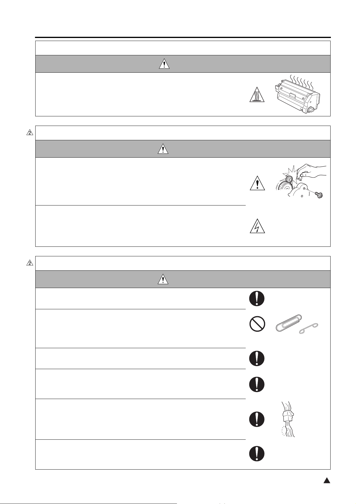
• Never use multi-plug adapters to plug multiple power cords in the same out-
let.
If used, the risk of fire exists.
• When an extension cord is required, use a specified one.
Current that can flow in the extension cord is limited, so using a too long
extension cord may result in fire.
Do not use an extension cable reel with the cable taken up. Fire may
result.
2.2. Installation Requirements
Prohibited Installation Place
WARNING
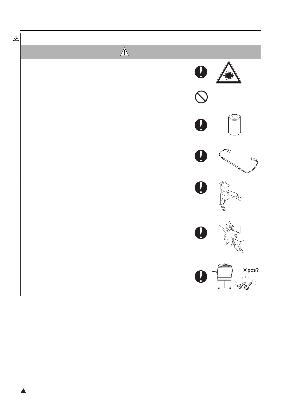
• Do not place the copier near flammable materials such as curtains or volatile
materials that may catch fire.
A risk of fire exists.
• Do not place the copier in a place exposed to water such as rain water.
A risk of fire and electric shock exists.
S-5
2

SAFETY AND IMPORTANT WARNING ITEMS
When not using product for a long time
WARNING
• When the copier is not used over an extended period of time (holidays, etc.),
switch it off and unplug the power cord.
Dust collected around the power plug and outlet may cause fire.
Ventilation
CAUTION
• The copier generates ozone gas during operation, but it is not sufficient to be
harmful to the human body.
If a bad smell of ozone is present in the following cases, ventilate the
room.
a. When the copier is used in a poorly ventilated room
b. When taking a lot of copies
c. When using multiple copiers at the same time
Fixing
CAUTION
• Be sure to lock the caster stoppers.
In the case of an earthquake and so on, the copier may slide, leading to a
injury.
Inspection before Servicing
CAUTION
• Before conducting an inspection, read all relevant documentation (service
manual, technical notices, etc.) and proceed with the inspection following the
prescribed procedure in safety clothes, using only the prescribed tools. Do
not make any adjustment not described in the documentation.
If the prescribed procedure or tool is not used, the copier may break and a
risk of injury or fire exists.
• Before conducting an inspection, be sure to disconnect the power plugs from
the copier and options.
When the power plug is inserted in the wall outlet, some units are still pow-
ered even if the POWER switch is turned OFF. A risk of electric shock
exists.
2
S-6
SAFETY AND IMPORTANT WARNING ITEMS
Inspection before Servicing
CAUTION
• The area around the fixing unit is hot.
You may get burnt.
Work Performed with the Copier Powered
WARNING
• Take every care when making adjustments or performing an operation check
with the copier powered.
If you make adjustments or perform an operation check with the external
cover detached, you may touch live or high-voltage parts or you may be
caught in moving gears or the timing belt, leading to a risk of injury.
• Take every care when servicing with the external cover detached.
High-voltage exists around the drum unit. A risk of electric shock exists.
Safety Checkpoints
WARNING
• Check the exterior and frame for edges, burrs, and other damages.
The user or CE may be injured.
• Be careful not to drop metal chips such as a clip, staple and/or a screw into
the inside of the product or its gaps.
A short circuit may occurs inside the product, thus resulting in an electric
shock and/or a fire.
• Check wiring for squeezing and any other damage.
Current can leak, leading to a risk of electric shock or fire.
• Carefully remove all toner remnants and dust from electrical parts and elec-
trode units such as a charging corona unit.
Current can leak, leading to a risk of copier trouble or fire.
• Check high-voltage cables and sheaths for any damage.
Current can leak, leading to a risk of electric shock or fire.
• Check electrode units such as a charging corona unit for deterioration and
sign of leakage.
Current can leak, leading to a risk of trouble or fire.
S-7
2
SAFETY AND IMPORTANT WARNING ITEMS
Safety Checkpoints
WARNING
• Before disassembling or adjusting the write unit incorporating a laser, make
sure that the power cord has been disconnected.
The laser light can enter your eye, leading to a risk of loss of eyesight.
• Do not remove the cover of the write unit. Do not supply power with the write
unit shifted from the specified mounting position.
The laser light can enter your eye, leading to a risk of loss of eyesight.
• When replacing a lithium battery, replace it with a new lithium battery speci-
fied in the Parts Guide Manual. Dispose of the used lithium battery using the
method specified by local authority.
Improper replacement can cause explosion.
• After replacing a part to which AC voltage is applied (e.g., optical lamp and
fixing lamp), be sure to check the installation state.
A risk of fire exists.
• Check the interlock switch and actuator for loosening and check whether the
interlock functions properly.
If the interlock does not function, you may receive an electric shock or be
injured when you insert your hand in the copier (e.g., for clearing paper
jam).
• Make sure the wiring cannot come into contact with sharp edges, burrs, or
other pointed parts.
Current can leak, leading to a risk of electric shock or fire.
• Make sure that all screws, components, wiring, connectors, etc. that were
removed for safety check and maintenance have been reinstalled in the orig-
inal location. (Pay special attention to forgotten connectors, pinched cables,
forgotten screws, etc.)
A risk of copier trouble, electric shock, and fire exists.
2
S-8
SAFETY AND IMPORTANT WARNING ITEMS
Consumables
WARNING
• Toner and developer are not harmful substances, but care must be taken not
to breathe excessive amounts or let the substances come into contact with
eyes, etc. It may be stimulative.
If the substances get in the eye, rinse with plenty of water immediately.
When symptoms are noticeable, consult a physician.
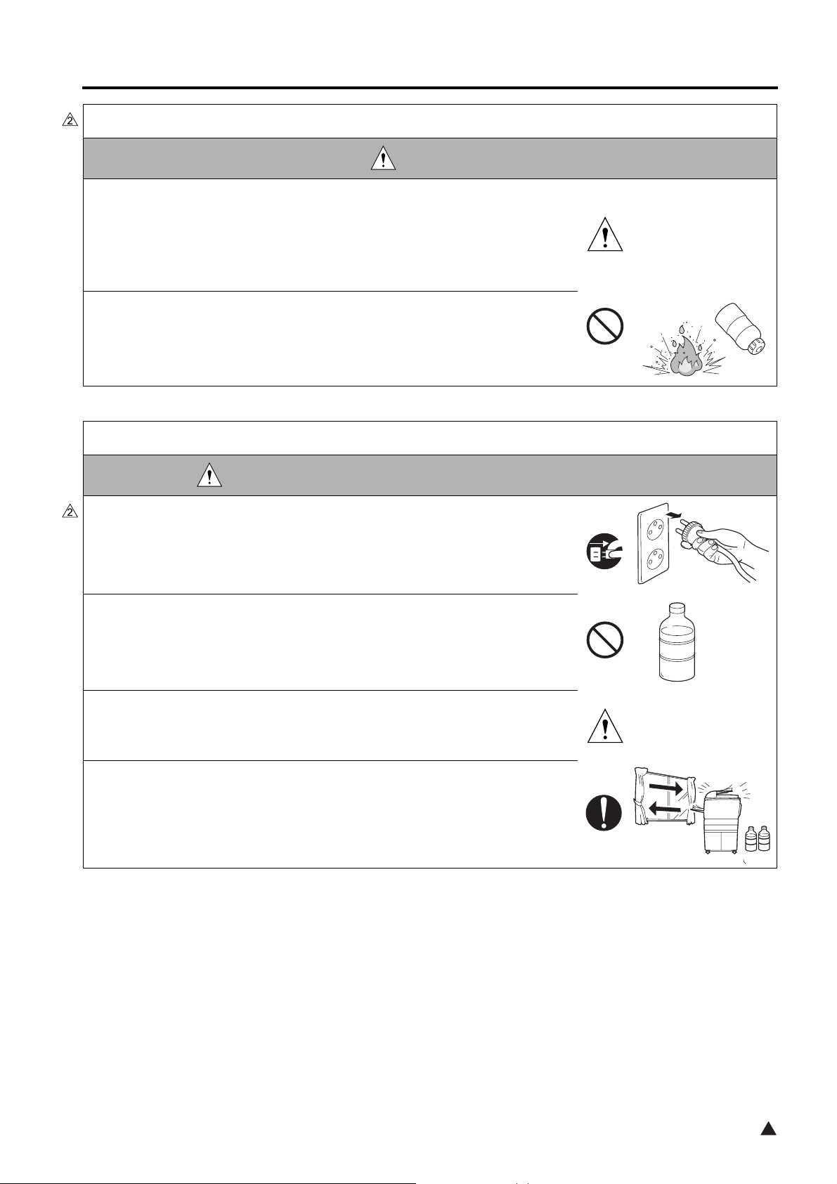
• Never throw the used cartridge and toner into fire.
You may be burned due to dust explosion.
HANDLING OF SERVICE MATERIALS
DANGER : HANDLING OF SERVICE MATERIALS
• When solution is used for cleaning, be sure to unplug the power cord from
the power outlet.
Drum cleaner (isopropyl alcohol) and roller cleaner (acetone-based) are
highly flammable and must be handled with care. A risk of fire exists.
• Do not replace the cover or turn the copier ON before any solvent remnants
on the cleaned parts have fully evaporated.
A risk of fire exists.
• Use only a small amount of cleaner at a time and take care not to spill any
liquid. If this happens, immediately wipe it off.
A risk of fire exists.
• When using any solvent, ventilate the room well.
Breathing large quantities of organic solvents can lead to discomfort.
S-9
2

SAFETY AND IMPORTANT WARNING ITEMS
SAFETY INFORMATION
IMPORTANT INFORMATION
The Center for Devices and Radiological Health (CDRH) of the U.S. Food and Drug Administration implemented
regulations for laser products manufactured since August 1, 1976. Compliance is mandatory for products mar-
keted in the United States.
This copier is certified as a “Class 1” laser product under the U.S.
Department of Health and Human Services (DHHS) Radiation Performance Standard according to the Radiation
Control for Health and Safety Act of 1968. Since radiation emitted inside this copier is completely confined within
protective housings and external covers, the laser beam cannot escape during any phase of normal user opera-
tion.
S-10
SAFETY AND IMPORTANT WARNING ITEMS
SAFETY CIRCUITS
This machine is provided with the following safety circuits to prevent machine faults from resulting in serious accidents.
• Overall protection circuit
• Fixing upper lamp /1 (L2), Fixing upper lamp /2 (L3), Fixing lower lamp (L4) overheating prevention circuit
These safety circuits are described below to provide the service engineer with a renewed awareness of them in order to pre-
vent servicing errors that may impair their functions.
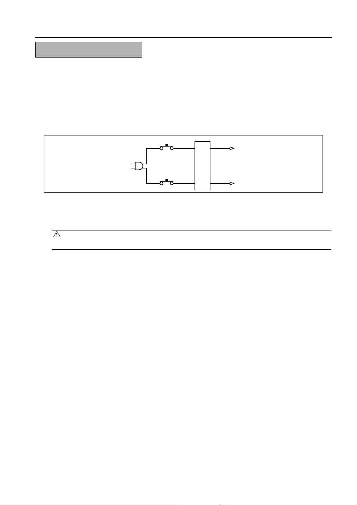
1. Overall protection circuit
CBR1
NF
CBR2
8050sf001
1.1 Protection by circuit breaker /1 (CBR1) and circuit breaker /2 (CBR2)
CBR1 and CBR2 interrupt the AC line instantaneously when an excessive current flows due to a short in the AC
line.
CAUTION:
The CBR1 and CBR2 functions must not be deactivated under any circumstances.
S-11
SAFETY AND IMPORTANT WARNING ITEMS
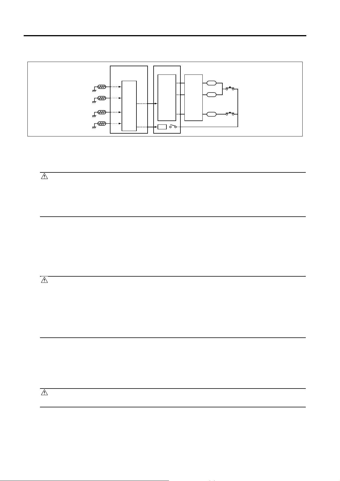
2. Fixing upper lamp /1 (L2), Fixing upper lamp /2 (L3), Fixing lower lamp (L4) overheating
prevention circuit
PRCB ACDB
TH1
TH3
TH2
TH4
Control
section
AC driver
section
RL1
RL1
FHCB
L2
TS1
L3
TS2
L4
8050sf002e
2.1 Protection by software
The output voltage from fixing temperature sensor /1 (TH1) and fixing temperature sensor /2 (TH2) is read by the
CPU. If this voltage is abnormal, L2, L3, and L4 are turned OFF by opening main relay (RL1).
CAUTION:
• The clearance between the fixing upper roller and TH1 and the clearance between the fixing
lower roller and TH2 must not be changed. When replacing them, make sure to comply with
the specified clearances.
• The RL1 function must not be deactivated under any circumstances.
2.2 Protection by the hardware circuit
The output voltages from fixing temperature sensor /1 (TH1), fixing temperature sensor /2 (TH2), fixing temperature
sensor /3 (TH3), and fixing temperature sensor /4 (TH4) are compared with the abnormality judgment reference
value in the comparator circuit. If the output voltage from TH1, TH2, TH3, or TH4 exceeds the reference value, L2,
L3, and L4 are turned OFF by opening RL1.
CAUTION:
• The clearance between the fixing upper roller and TH1 and the clearance between the fixing
lower roller and TH2 must not be changed. When replacing them, make sure to comply with
the specified clearances.
• Periodically check the contact between the fixing upper roller and TH3 and the contact
between the fixing lower roller and TH4, and replace them if any abnormality is detected.
• The RL1 function must not be deactivated under any circumstances.
2.3 Protection by thermostat /1 (TS1) and thermostat /2 (TS2)
When the temperature of the fixing upper roller exceeds the specified value, TS1 is turned OFF, thus interrupting the
power to L2 and L3 directly. When the temperature of the fixing lower roller exceeds the specified value, TS2 is
turned OFF, thus interrupting the power to L4 directly.
CAUTION:
Do not use any other electrical conductor in place of TS1 and TS2.
S-12
SAFETY AND IMPORTANT WARNING ITEMS
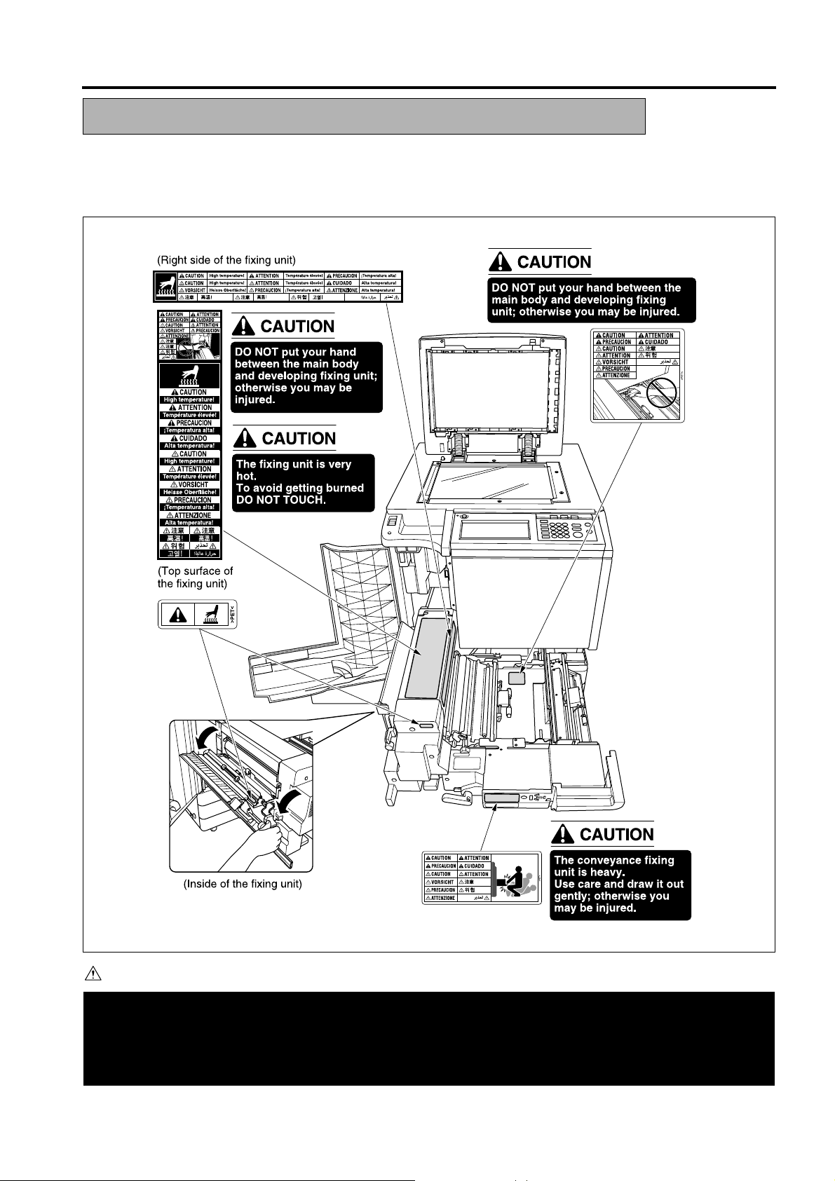
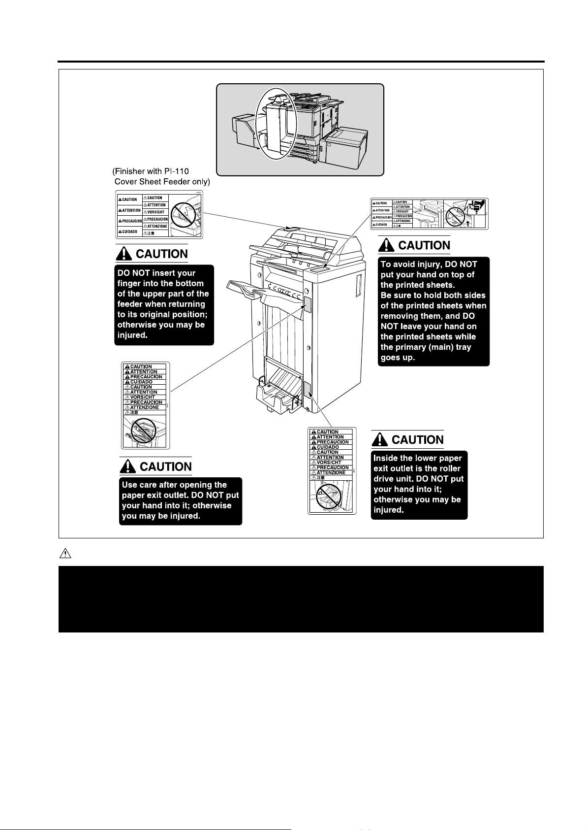
INDICATION OF WARNING ON THE MACHINE
Caution labels shown below are attached in some areas on/in the machine.
When accessing these areas for maintenance, repair, or adjustment, special care should be taken to avoid burns and electric
shock.
8050sf003e
CAUTION
You may be burned or injured if you touch any area that you are advised by any caution label to keep your-
self away from.
Do not remove caution labels. If any caution label has come off or soiled and therefore the caution cannot
be read, contact our Service Office.
S-13
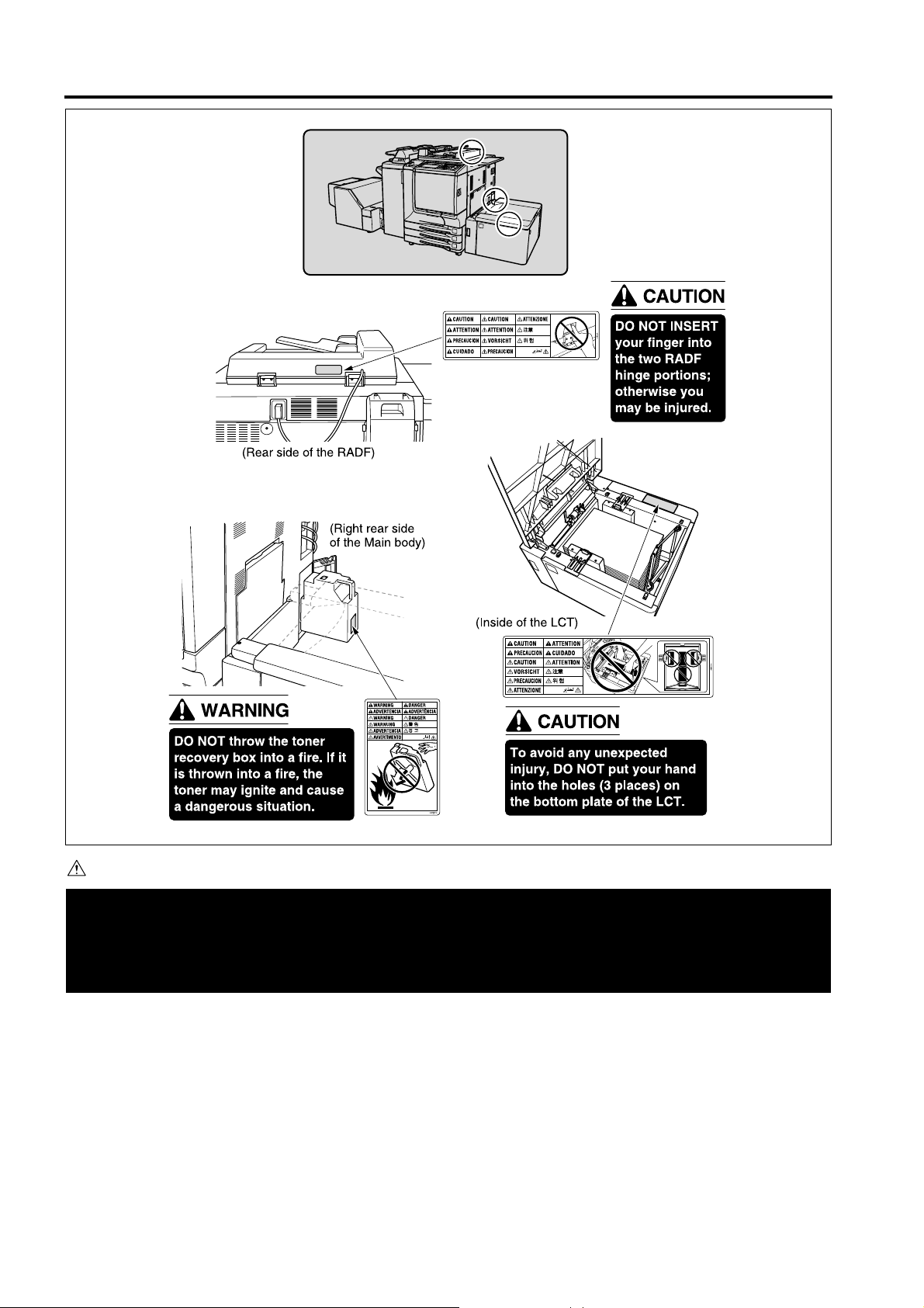
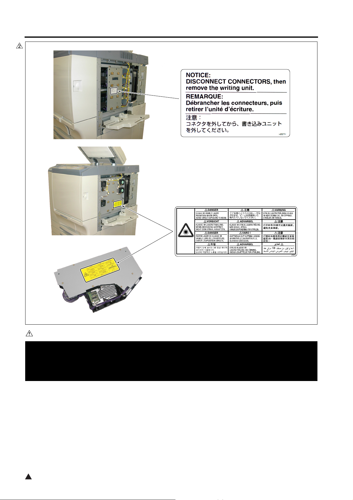
SAFETY AND IMPORTANT WARNING ITEMS
8050sf004e
CAUTION
You may be burned or injured if you touch any area that you are advised by any caution label to keep your-
self away from.
Do not remove caution labels. If any caution label has come off or soiled and therefore the caution cannot
be read, contact our Service Office.
S-14
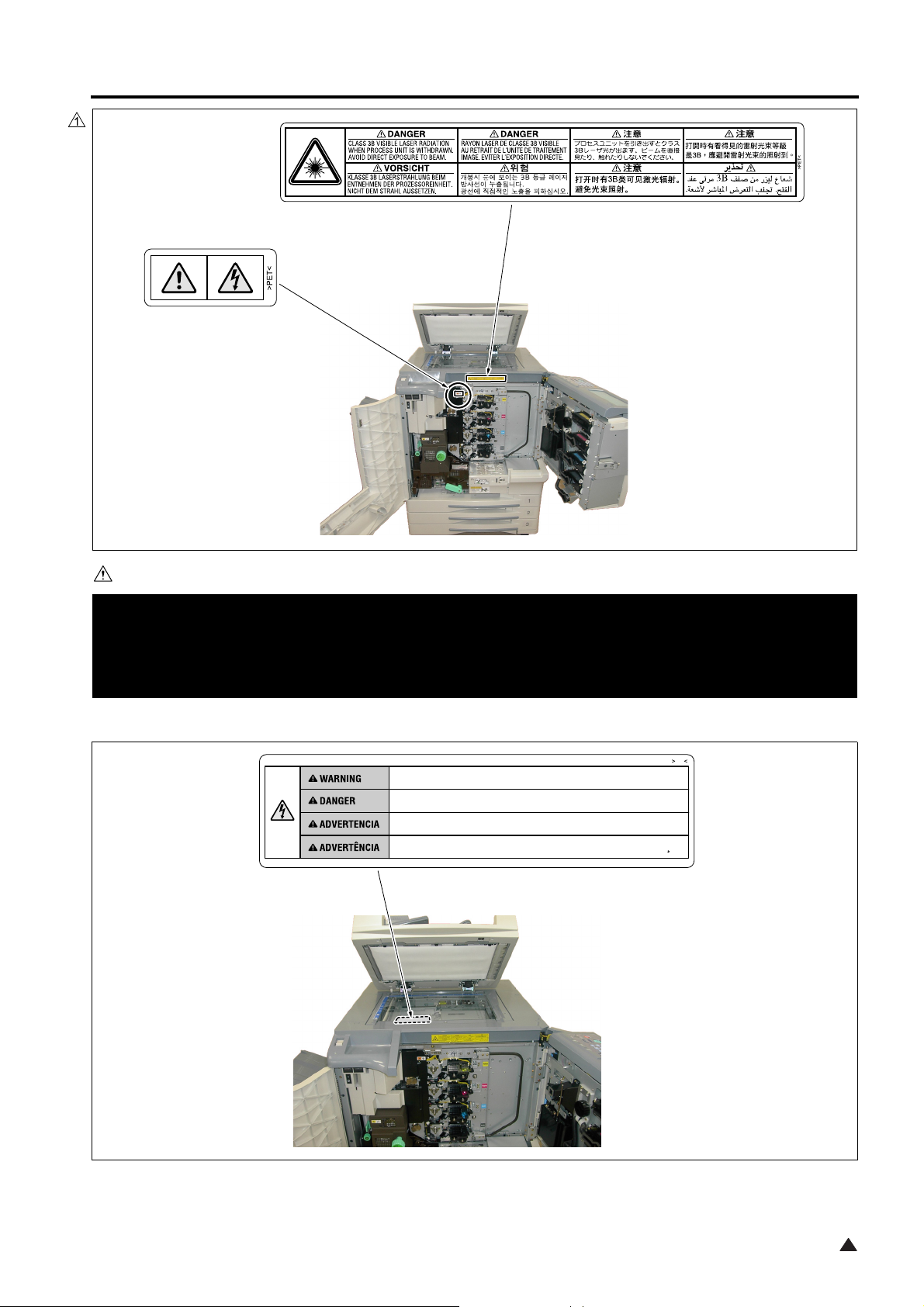
SAFETY AND IMPORTANT WARNING ITEMS
8050sf005e
CAUTION
You may be burned or injured if you touch any area that you are advised by any caution label to keep your-
self away from.
Do not remove caution labels. If any caution label has come off or soiled and therefore the caution cannot
be read, contact our Service Office.
S-15
SAFETY AND IMPORTANT WARNING ITEMS
8050sf006e
CAUTION
You may be burned or injured if you touch any area that you are advised by any caution label to keep your-
self away from.
Do not remove caution labels. If any caution label has come off or soiled and therefore the caution cannot
be read, contact our Service Office.
2
S-16
SAFETY AND IMPORTANT WARNING ITEMS
8050sf007e
CAUTION
You may be burned or injured if you touch any area that you are advised by any caution label to keep your-
self away from.
Do not remove caution labels. If any caution label has come off or soiled and therefore the caution cannot
be read, contact our Service Office.
PS
Unplug the machine before removing platen glass.
Debrancher le copieur avant de retirer la vitre d'exposition.
Desenchufe la maquina antes de quitar el vidrio.
Desconecte a unidade da tomada antes de remover o vidro de exposicao.
~
S-17
8050sf008e
1
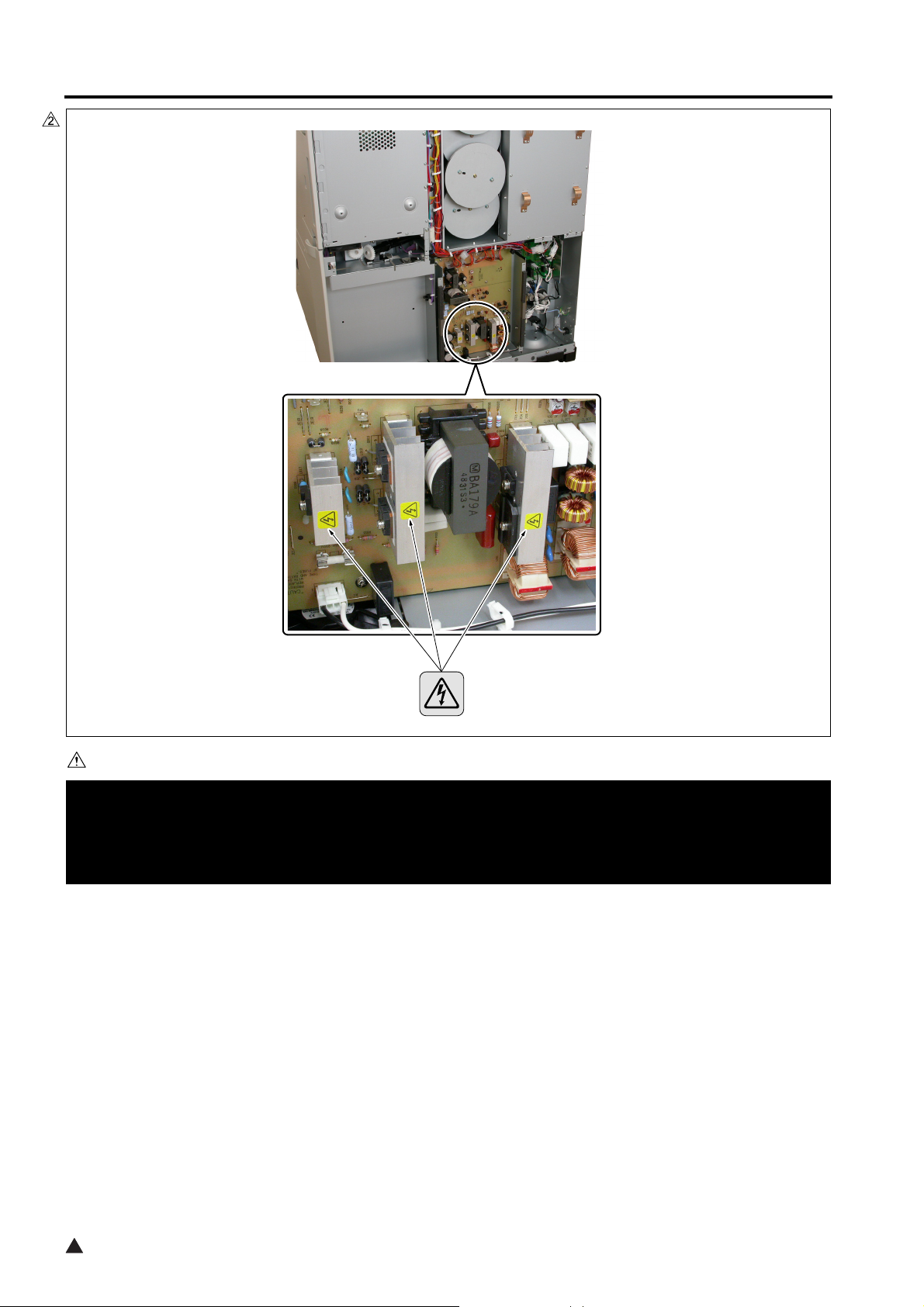
SAFETY AND IMPORTANT WARNING ITEMS
8050sf009
CAUTION
You may be burned or injured if you touch any area that you are advised by any caution label to keep your-
self away from.
Do not remove caution labels. If any caution label has come off or soiled and therefore the caution cannot
be read, contact our Service Office.
2
S-18

KONICA MINOLTA 8050/CF5001/C500/8150 Field Service Ver.3.0 Dec. 2004
CONTENTS
CONTENTS
SAFETY AND IMPORTANT WARNING ITEMS. . . . . . . . . . . . . . . . . . . . . . . . . . . . . . . . . . . . . . . . . . . . . S-1
IMPORTANT NOTICE . . . . . . . . . . . . . . . . . . . . . . . . . . . . . . . . . . . . . . . . . . . . . . . . . . . . . . . . . . . . . . . S-1
DESCRIPTION ITEMS FOR DANGER, WARNING AND CAUTION . . . . . . . . . . . . . . . . . . . . . . . . . . . . S-1
SAFETY WARNINGS . . . . . . . . . . . . . . . . . . . . . . . . . . . . . . . . . . . . . . . . . . . . . . . . . . . . . . . . . . . . . . . . S-2
SAFETY INFORMATION . . . . . . . . . . . . . . . . . . . . . . . . . . . . . . . . . . . . . . . . . . . . . . . . . . . . . . . . . . . . . S-10
IMPORTANT INFORMATION . . . . . . . . . . . . . . . . . . . . . . . . . . . . . . . . . . . . . . . . . . . . . . . . . . . . . . . . . S-10
SAFETY CIRCUITS . . . . . . . . . . . . . . . . . . . . . . . . . . . . . . . . . . . . . . . . . . . . . . . . . . . . . . . . . . . . . . . . S-11
INDICATION OF WARNING ON THE MACHINE . . . . . . . . . . . . . . . . . . . . . . . . . . . . . . . . . . . . . . . . . . S-13
Introduction . . . . . . . . . . . . . . . . . . . . . . . . . . . . . . . . . . . . . . . . . . . . . . . . . . . . . . . . . . . . . . . . . . . . . . . . . vii
Revision history . . . . . . . . . . . . . . . . . . . . . . . . . . . . . . . . . . . . . . . . . . . . . . . . . . . . . . . . . . . . . . . . . . . . vii
Composition of the service manual . . . . . . . . . . . . . . . . . . . . . . . . . . . . . . . . . . . . . . . . . . . . . . . . . . . . . viii
Notation of the service manual . . . . . . . . . . . . . . . . . . . . . . . . . . . . . . . . . . . . . . . . . . . . . . . . . . . . . . . . .ix
Measures to take in case of an accident . . . . . . . . . . . . . . . . . . . . . . . . . . . . . . . . . . . . . . . . . . . . . . . . . . . .xi
I ADJUSTMENTII SERVICE TOOLIII SERVICEIV JAM CODE LISTV ERROR CODE LISTVI DIAGRAMS
List of major differences between the old type and the new type . . . . . . . . . . . . . . . . . . . . . . . . . . . . . . . . xii
IADJUSTMENT
1. HOW TO USE THE ADJUSTMENT SECTION . . . . . . . . . . . . . . . . . . . . . . . . . . . . . . . . . . . . . . . . . . 1-1
1.1 Composition. . . . . . . . . . . . . . . . . . . . . . . . . . . . . . . . . . . . . . . . . . . . . . . . . . . . . . . . . . . . . . . . . . 1-1
2. ADJUSTMENTS WHEN REPLACING PARTS. . . . . . . . . . . . . . . . . . . . . . . . . . . . . . . . . . . . . . . . . . . 1-1
3. LIST OF ADJUSTMENT ITEMS . . . . . . . . . . . . . . . . . . . . . . . . . . . . . . . . . . . . . . . . . . . . . . . . . . . . . . 1-2
4. MODE CHANGE MENU . . . . . . . . . . . . . . . . . . . . . . . . . . . . . . . . . . . . . . . . . . . . . . . . . . . . . . . . . . . . 1-4
4.1 Setting method . . . . . . . . . . . . . . . . . . . . . . . . . . . . . . . . . . . . . . . . . . . . . . . . . . . . . . . . . . . . . . . 1-4
5. CHECKING BY THE P FUNCTION . . . . . . . . . . . . . . . . . . . . . . . . . . . . . . . . . . . . . . . . . . . . . . . . . . . 1-4
5.1 Checking method of the P function . . . . . . . . . . . . . . . . . . . . . . . . . . . . . . . . . . . . . . . . . . . . . . . . 1-4
6. 25 MODE . . . . . . . . . . . . . . . . . . . . . . . . . . . . . . . . . . . . . . . . . . . . . . . . . . . . . . . . . . . . . . . . . . . . . . . 1-5
6.1 List of adjustment items for 25 mode. . . . . . . . . . . . . . . . . . . . . . . . . . . . . . . . . . . . . . . . . . . . . . . 1-5
6.2 Setting method . . . . . . . . . . . . . . . . . . . . . . . . . . . . . . . . . . . . . . . . . . . . . . . . . . . . . . . . . . . . . . . 1-6
6.3 Setting software DIPSW . . . . . . . . . . . . . . . . . . . . . . . . . . . . . . . . . . . . . . . . . . . . . . . . . . . . . . . . 1-6
6.4 Paper size setting . . . . . . . . . . . . . . . . . . . . . . . . . . . . . . . . . . . . . . . . . . . . . . . . . . . . . . . . . . . . 1-22
6.4.1 Standard size setting . . . . . . . . . . . . . . . . . . . . . . . . . . . . . . . . . . . . . . . . . . . . . . . . . . . . . 1-22
6.4.2 Non-standard size setting . . . . . . . . . . . . . . . . . . . . . . . . . . . . . . . . . . . . . . . . . . . . . . . . . 1-22
6.4.3 Wide paper setting . . . . . . . . . . . . . . . . . . . . . . . . . . . . . . . . . . . . . . . . . . . . . . . . . . . . . . . 1-22
6.5 PM count setting . . . . . . . . . . . . . . . . . . . . . . . . . . . . . . . . . . . . . . . . . . . . . . . . . . . . . . . . . . . . . 1-23
6.5.1 Count reset. . . . . . . . . . . . . . . . . . . . . . . . . . . . . . . . . . . . . . . . . . . . . . . . . . . . . . . . . . . . . 1-23
6.5.2 Change setting . . . . . . . . . . . . . . . . . . . . . . . . . . . . . . . . . . . . . . . . . . . . . . . . . . . . . . . . . . 1-23
6.6 Data collection . . . . . . . . . . . . . . . . . . . . . . . . . . . . . . . . . . . . . . . . . . . . . . . . . . . . . . . . . . . . . . . 1-24
6.7 Parts counter . . . . . . . . . . . . . . . . . . . . . . . . . . . . . . . . . . . . . . . . . . . . . . . . . . . . . . . . . . . . . . . . 1-40
6.7.1 Count of special parts . . . . . . . . . . . . . . . . . . . . . . . . . . . . . . . . . . . . . . . . . . . . . . . . . . . . 1-40
6.7.2 Count of each parts . . . . . . . . . . . . . . . . . . . . . . . . . . . . . . . . . . . . . . . . . . . . . . . . . . . . . . 1-47
6.8 Password setting . . . . . . . . . . . . . . . . . . . . . . . . . . . . . . . . . . . . . . . . . . . . . . . . . . . . . . . . . . . . . 1-49
i
2

CONTENTS
6.9 Telephone number setting . . . . . . . . . . . . . . . . . . . . . . . . . . . . . . . . . . . . . . . . . . . . . . . . . . . . . . 1-49
6.10 M/C serial number setting . . . . . . . . . . . . . . . . . . . . . . . . . . . . . . . . . . . . . . . . . . . . . . . . . . . . . . 1-50
6.11 Indication of ROM version . . . . . . . . . . . . . . . . . . . . . . . . . . . . . . . . . . . . . . . . . . . . . . . . . . . . . . 1-50
6.12 KRDS setting . . . . . . . . . . . . . . . . . . . . . . . . . . . . . . . . . . . . . . . . . . . . . . . . . . . . . . . . . . . . . . . . 1-50
6.13 ISW . . . . . . . . . . . . . . . . . . . . . . . . . . . . . . . . . . . . . . . . . . . . . . . . . . . . . . . . . . . . . . . . . . . . . . . 1-50
6.14 Setting date input . . . . . . . . . . . . . . . . . . . . . . . . . . . . . . . . . . . . . . . . . . . . . . . . . . . . . . . . . . . . . 1-51
I ADJUSTMENT
6.15 Board change mode. . . . . . . . . . . . . . . . . . . . . . . . . . . . . . . . . . . . . . . . . . . . . . . . . . . . . . . . . . . 1-51
7. 36 MODE . . . . . . . . . . . . . . . . . . . . . . . . . . . . . . . . . . . . . . . . . . . . . . . . . . . . . . . . . . . . . . . . . . . . . . 1-52
7.1 Setting method. . . . . . . . . . . . . . . . . . . . . . . . . . . . . . . . . . . . . . . . . . . . . . . . . . . . . . . . . . . . . . . 1-52
7.2 Process adjustment . . . . . . . . . . . . . . . . . . . . . . . . . . . . . . . . . . . . . . . . . . . . . . . . . . . . . . . . . . . 1-52
7.2.1 High voltage adjustment . . . . . . . . . . . . . . . . . . . . . . . . . . . . . . . . . . . . . . . . . . . . . . . . . . . 1-53
7.2.2 Drum peculiarity adjustment . . . . . . . . . . . . . . . . . . . . . . . . . . . . . . . . . . . . . . . . . . . . . . . . 1-53
7.2.3 Sensor output check. . . . . . . . . . . . . . . . . . . . . . . . . . . . . . . . . . . . . . . . . . . . . . . . . . . . . . 1-59
7.2.4 Exclusive paper setting. . . . . . . . . . . . . . . . . . . . . . . . . . . . . . . . . . . . . . . . . . . . . . . . . . . . 1-59
7.2.5 Recall standard data. . . . . . . . . . . . . . . . . . . . . . . . . . . . . . . . . . . . . . . . . . . . . . . . . . . . . . 1-61
II SERVICE TOOL
7.3 Image adjustment . . . . . . . . . . . . . . . . . . . . . . . . . . . . . . . . . . . . . . . . . . . . . . . . . . . . . . . . . . . . 1-62
7.3.1 Magnification adjustment . . . . . . . . . . . . . . . . . . . . . . . . . . . . . . . . . . . . . . . . . . . . . . . . . . 1-62
7.3.2 Timing adjustment . . . . . . . . . . . . . . . . . . . . . . . . . . . . . . . . . . . . . . . . . . . . . . . . . . . . . . . 1-68
7.3.3 RADF adjustment . . . . . . . . . . . . . . . . . . . . . . . . . . . . . . . . . . . . . . . . . . . . . . . . . . . . . . . . 1-76
7.3.4 Centring adjustment . . . . . . . . . . . . . . . . . . . . . . . . . . . . . . . . . . . . . . . . . . . . . . . . . . . . . . 1-78
7.3.5 Non-image area erase check . . . . . . . . . . . . . . . . . . . . . . . . . . . . . . . . . . . . . . . . . . . . . . . 1-80
7.3.6 Recall standard data. . . . . . . . . . . . . . . . . . . . . . . . . . . . . . . . . . . . . . . . . . . . . . . . . . . . . . 1-81
III SERVICEIV JAM CODE LISTV ERROR CODE LISTVI DIAGRAMS
7.4 Image quality adjustment . . . . . . . . . . . . . . . . . . . . . . . . . . . . . . . . . . . . . . . . . . . . . . . . . . . . . . . 1-82
7.4.1 Scanner gamma adjustment. . . . . . . . . . . . . . . . . . . . . . . . . . . . . . . . . . . . . . . . . . . . . . . . 1-82
7.4.2 Printer gamma adjustment . . . . . . . . . . . . . . . . . . . . . . . . . . . . . . . . . . . . . . . . . . . . . . . . . 1-83
7.4.3 Sharpness adjustment . . . . . . . . . . . . . . . . . . . . . . . . . . . . . . . . . . . . . . . . . . . . . . . . . . . . 1-88
7.4.4 Contrast adjustment . . . . . . . . . . . . . . . . . . . . . . . . . . . . . . . . . . . . . . . . . . . . . . . . . . . . . . 1-89
7.4.5 Image judge adjustment . . . . . . . . . . . . . . . . . . . . . . . . . . . . . . . . . . . . . . . . . . . . . . . . . . . 1-89
7.4.6 ACS adjustment . . . . . . . . . . . . . . . . . . . . . . . . . . . . . . . . . . . . . . . . . . . . . . . . . . . . . . . . . 1-91
7.4.7 Density adjustment . . . . . . . . . . . . . . . . . . . . . . . . . . . . . . . . . . . . . . . . . . . . . . . . . . . . . . . 1-92
7.4.8 Tone adjustment . . . . . . . . . . . . . . . . . . . . . . . . . . . . . . . . . . . . . . . . . . . . . . . . . . . . . . . . . 1-94
7.4.9 Recall standard data. . . . . . . . . . . . . . . . . . . . . . . . . . . . . . . . . . . . . . . . . . . . . . . . . . . . . . 1-95
7.5 Running test mode. . . . . . . . . . . . . . . . . . . . . . . . . . . . . . . . . . . . . . . . . . . . . . . . . . . . . . . . . . . . 1-96
7.5.1 Setting method . . . . . . . . . . . . . . . . . . . . . . . . . . . . . . . . . . . . . . . . . . . . . . . . . . . . . . . . . . 1-96
7.6 Test pattern output mode . . . . . . . . . . . . . . . . . . . . . . . . . . . . . . . . . . . . . . . . . . . . . . . . . . . . . . . 1-97
7.7 Test pattern density setting . . . . . . . . . . . . . . . . . . . . . . . . . . . . . . . . . . . . . . . . . . . . . . . . . . . . 1-106
7.8 Finisher adjustment . . . . . . . . . . . . . . . . . . . . . . . . . . . . . . . . . . . . . . . . . . . . . . . . . . . . . . . . . . 1-106
7.8.1 Stitch and fold stopper adjustment (FS-215/FN-9/FS-606 only). . . . . . . . . . . . . . . . . . . . 1-107
7.8.2 Fold stopper adjustment (FS-215/FN-9/FS-606 only) . . . . . . . . . . . . . . . . . . . . . . . . . . . 1-107
7.8.3 Cover sheet tray size adjustment (PI-110 only) . . . . . . . . . . . . . . . . . . . . . . . . . . . . . . . . 1-108
7.8.4 Trimming stopper adjustment (TU-109/TMG-3 only) . . . . . . . . . . . . . . . . . . . . . . . . . . . . 1-108
7.8.5 Punch adjustment (PK-120/PK-5/PK-507 only) . . . . . . . . . . . . . . . . . . . . . . . . . . . . . . . . 1-109
7.8.6 Three-folding adjustment (FS-215/FN-9/FS-606 only) . . . . . . . . . . . . . . . . . . . . . . . . . . . 1-111
7.8.7 2 positions staple pitch adjustment. . . . . . . . . . . . . . . . . . . . . . . . . . . . . . . . . . . . . . . . . . 1-112
7.9 List output mode . . . . . . . . . . . . . . . . . . . . . . . . . . . . . . . . . . . . . . . . . . . . . . . . . . . . . . . . . . . . 1-112
8. 47 MODE . . . . . . . . . . . . . . . . . . . . . . . . . . . . . . . . . . . . . . . . . . . . . . . . . . . . . . . . . . . . . . . . . . . . . 1-113
8.1 47 mode/multi mode setting method . . . . . . . . . . . . . . . . . . . . . . . . . . . . . . . . . . . . . . . . . . . . . 1-113
KONICA MINOLTA 8050/CF5001/C500/8150 Field Service Ver.3.0 Dec. 2004
2
ii

KONICA MINOLTA 8050/CF5001/C500/8150 Field Service Ver.3.0 Dec. 2004
CONTENTS
8.2 Adjustment data display . . . . . . . . . . . . . . . . . . . . . . . . . . . . . . . . . . . . . . . . . . . . . . . . . . . . . . 1-114
8.3 Hard disk check . . . . . . . . . . . . . . . . . . . . . . . . . . . . . . . . . . . . . . . . . . . . . . . . . . . . . . . . . . . . . 1-114
8.4 Input check list. . . . . . . . . . . . . . . . . . . . . . . . . . . . . . . . . . . . . . . . . . . . . . . . . . . . . . . . . . . . . . 1-116
8.5 Output check list . . . . . . . . . . . . . . . . . . . . . . . . . . . . . . . . . . . . . . . . . . . . . . . . . . . . . . . . . . . . 1-127
9. OTHER ADJUSTMENTS . . . . . . . . . . . . . . . . . . . . . . . . . . . . . . . . . . . . . . . . . . . . . . . . . . . . . . . . . 1-139
9.1 Paper feed roller/BP pressure adjustment. . . . . . . . . . . . . . . . . . . . . . . . . . . . . . . . . . . . . . . . . 1-139
9.2 Paper feed height (upper limit) adjustment (bypass). . . . . . . . . . . . . . . . . . . . . . . . . . . . . . . . . 1-140
9.3 Pick-up movement amount adjustment (bypass) . . . . . . . . . . . . . . . . . . . . . . . . . . . . . . . . . . . 1-142
9.4 Paper feed tray /1 to /3 mis-centering adjustment. . . . . . . . . . . . . . . . . . . . . . . . . . . . . . . . . . . 1-143
9.5 Paper feed tray/1 to /3 sheet feed pressure adjustment . . . . . . . . . . . . . . . . . . . . . . . . . . . . . . 1-144
9.6 FNS adjustment of the bypass conveyance guide plate magnet. . . . . . . . . . . . . . . . . . . . . . . . 1-146
9.7 FNS adjustment of the bypass gate . . . . . . . . . . . . . . . . . . . . . . . . . . . . . . . . . . . . . . . . . . . . . 1-147
9.8 FNS adjustment of the shift position . . . . . . . . . . . . . . . . . . . . . . . . . . . . . . . . . . . . . . . . . . . . . 1-149
9.9 FNS adjustment of the paper exit opening solenoid . . . . . . . . . . . . . . . . . . . . . . . . . . . . . . . . . 1-150
9.10 FNS adjustment of the position of paper exit arm . . . . . . . . . . . . . . . . . . . . . . . . . . . . . . . . . . . 1-152
9.11 FNS adjustment of the position of alignment plate /U . . . . . . . . . . . . . . . . . . . . . . . . . . . . . . . . 1-154
9.12 FNS adjustment of the position of alignment plate /L (only for FS-215/FN-9/FS-606) . . . . . . . 1-156
9.13 FNS adjustment of the stapling position (flat stapling) . . . . . . . . . . . . . . . . . . . . . . . . . . . . . . . 1-158
9.14 FNS adjustment of the stapling position in a vertical direction . . . . . . . . . . . . . . . . . . . . . . . . . 1-160
9.15 FNS adjustment of the stapling position (flat stapling) (only for FS-215/FN-9/FS-606). . . . . . . 1-168
9.16 FNS adjustment of the angle of the folding stopper (only for FS-215/FN-9/FS-606). . . . . . . . . 1-170
9.17 FNS adjustment of the folding force (only for FS-215/FN-9/FS-606) . . . . . . . . . . . . . . . . . . . . 1-172
9.18 FNS adjustment of the three-holding position (only for FS-215/FN-9/FS-606) . . . . . . . . . . . . . 1-173
9.19 FNS adjustment of the stapler drive belt position . . . . . . . . . . . . . . . . . . . . . . . . . . . . . . . . . . . 1-174
9.20 TU adjustment of the sheet cutting parallelism . . . . . . . . . . . . . . . . . . . . . . . . . . . . . . . . . . . . . 1-178
9.21 LCT tray mis-centering adjustment . . . . . . . . . . . . . . . . . . . . . . . . . . . . . . . . . . . . . . . . . . . . . . 1-179
9.22 LCT skew adjustment . . . . . . . . . . . . . . . . . . . . . . . . . . . . . . . . . . . . . . . . . . . . . . . . . . . . . . . . 1-181
9.23 LCT paper feed roller pressure adjustment . . . . . . . . . . . . . . . . . . . . . . . . . . . . . . . . . . . . . . . . 1-183
9.24 LCT up/down plate horizontal adjustment . . . . . . . . . . . . . . . . . . . . . . . . . . . . . . . . . . . . . . . . . 1-184
9.25 LCT sheet feed pressure adjustment . . . . . . . . . . . . . . . . . . . . . . . . . . . . . . . . . . . . . . . . . . . . 1-185
9.26 LCT paper feed height (upper limit) adjustment . . . . . . . . . . . . . . . . . . . . . . . . . . . . . . . . . . . . 1-186
9.27 LCT pick-up release amount adjustment. . . . . . . . . . . . . . . . . . . . . . . . . . . . . . . . . . . . . . . . . . 1-188
I ADJUSTMENTII SERVICE TOOLIII SERVICEIV JAM CODE LISTV ERROR CODE LISTVI DIAGRAMS
II SERVICE TOOL
1. Description of the ISW . . . . . . . . . . . . . . . . . . . . . . . . . . . . . . . . . . . . . . . . . . . . . . . . . . . . . . . . . . . . . 2-1
1.1 Setup . . . . . . . . . . . . . . . . . . . . . . . . . . . . . . . . . . . . . . . . . . . . . . . . . . . . . . . . . . . . . . . . . . . . . . . 2-1
1.1.1 Board used for the ISW . . . . . . . . . . . . . . . . . . . . . . . . . . . . . . . . . . . . . . . . . . . . . . . . . . . . 2-1
1.1.2 Data flow . . . . . . . . . . . . . . . . . . . . . . . . . . . . . . . . . . . . . . . . . . . . . . . . . . . . . . . . . . . . . . . 2-1
1.1.3 ISW transfer type . . . . . . . . . . . . . . . . . . . . . . . . . . . . . . . . . . . . . . . . . . . . . . . . . . . . . . . . . 2-1
1.1.4 Instances of ISW transfer . . . . . . . . . . . . . . . . . . . . . . . . . . . . . . . . . . . . . . . . . . . . . . . . . . . 2-3
1.1.5 Setup procedure. . . . . . . . . . . . . . . . . . . . . . . . . . . . . . . . . . . . . . . . . . . . . . . . . . . . . . . . . . 2-4
2. USB ISW. . . . . . . . . . . . . . . . . . . . . . . . . . . . . . . . . . . . . . . . . . . . . . . . . . . . . . . . . . . . . . . . . . . . . . . . 2-9
2.1 What is the USB ISW? . . . . . . . . . . . . . . . . . . . . . . . . . . . . . . . . . . . . . . . . . . . . . . . . . . . . . . . . . 2-9
3. INTERNET ISW . . . . . . . . . . . . . . . . . . . . . . . . . . . . . . . . . . . . . . . . . . . . . . . . . . . . . . . . . . . . . . . . . 2-11
3.1 What is the Internet ISW? . . . . . . . . . . . . . . . . . . . . . . . . . . . . . . . . . . . . . . . . . . . . . . . . . . . . . . 2-11
3.2 Operating environment . . . . . . . . . . . . . . . . . . . . . . . . . . . . . . . . . . . . . . . . . . . . . . . . . . . . . . . . 2-11
3.3 Main features. . . . . . . . . . . . . . . . . . . . . . . . . . . . . . . . . . . . . . . . . . . . . . . . . . . . . . . . . . . . . . . . 2-11
iii
2

CONTENTS
3.4 Initial setting . . . . . . . . . . . . . . . . . . . . . . . . . . . . . . . . . . . . . . . . . . . . . . . . . . . . . . . . . . . . . . . . . 2-12
3.4.1 Setting on Control panel . . . . . . . . . . . . . . . . . . . . . . . . . . . . . . . . . . . . . . . . . . . . . . . . . . . 2-12
3.4.2 Setting on Web browser . . . . . . . . . . . . . . . . . . . . . . . . . . . . . . . . . . . . . . . . . . . . . . . . . . . 2-12
3.5 Internet ISW using E-Mail remote notification system . . . . . . . . . . . . . . . . . . . . . . . . . . . . . . . . . 2-20
3.5.1 Function . . . . . . . . . . . . . . . . . . . . . . . . . . . . . . . . . . . . . . . . . . . . . . . . . . . . . . . . . . . . . . . 2-20
3.5.2 Transmitting E-Mail. . . . . . . . . . . . . . . . . . . . . . . . . . . . . . . . . . . . . . . . . . . . . . . . . . . . . . . 2-21
I ADJUSTMENT
3.6 Internet ISW using Web utility . . . . . . . . . . . . . . . . . . . . . . . . . . . . . . . . . . . . . . . . . . . . . . . . . . . 2-26
3.6.1 Function . . . . . . . . . . . . . . . . . . . . . . . . . . . . . . . . . . . . . . . . . . . . . . . . . . . . . . . . . . . . . . . 2-26
3.6.2 How to use . . . . . . . . . . . . . . . . . . . . . . . . . . . . . . . . . . . . . . . . . . . . . . . . . . . . . . . . . . . . . 2-26
3.7 Precautions for use . . . . . . . . . . . . . . . . . . . . . . . . . . . . . . . . . . . . . . . . . . . . . . . . . . . . . . . . . . . 2-29
3.7.1 Prior announcement to administrator . . . . . . . . . . . . . . . . . . . . . . . . . . . . . . . . . . . . . . . . . 2-29
3.7.2 If power failure occurs during data rewriting. . . . . . . . . . . . . . . . . . . . . . . . . . . . . . . . . . . . 2-29
3.7.3 ISW of multiple programs . . . . . . . . . . . . . . . . . . . . . . . . . . . . . . . . . . . . . . . . . . . . . . . . . . 2-29
3.7.4 If ISW fails in low power mode . . . . . . . . . . . . . . . . . . . . . . . . . . . . . . . . . . . . . . . . . . . . . . 2-29
3.8 Proxy server authentication in Internet ISW. . . . . . . . . . . . . . . . . . . . . . . . . . . . . . . . . . . . . . . . . 2-30
II SERVICE TOOL
3.8.1 What is a proxy server? . . . . . . . . . . . . . . . . . . . . . . . . . . . . . . . . . . . . . . . . . . . . . . . . . . . 2-30
3.8.2 Authentication of proxy server . . . . . . . . . . . . . . . . . . . . . . . . . . . . . . . . . . . . . . . . . . . . . . 2-30
3.8.3 Type and command list for authentication on proxy server . . . . . . . . . . . . . . . . . . . . . . . . 2-30
3.8.4 Remarks . . . . . . . . . . . . . . . . . . . . . . . . . . . . . . . . . . . . . . . . . . . . . . . . . . . . . . . . . . . . . . . 2-31
4. MAIL REMOTE NOTIFICATION SYSTEM . . . . . . . . . . . . . . . . . . . . . . . . . . . . . . . . . . . . . . . . . . . . . 2-32
4.1 What is the Mail remote notification system?. . . . . . . . . . . . . . . . . . . . . . . . . . . . . . . . . . . . . . . . 2-32
4.2 Operation environment . . . . . . . . . . . . . . . . . . . . . . . . . . . . . . . . . . . . . . . . . . . . . . . . . . . . . . . . 2-32
III SERVICEIV JAM CODE LISTV ERROR CODE LISTVI DIAGRAMS
4.3 Initial setting . . . . . . . . . . . . . . . . . . . . . . . . . . . . . . . . . . . . . . . . . . . . . . . . . . . . . . . . . . . . . . . . . 2-32
4.4 How to use the Mail remote notification system. . . . . . . . . . . . . . . . . . . . . . . . . . . . . . . . . . . . . . 2-39
4.5 Disabling system . . . . . . . . . . . . . . . . . . . . . . . . . . . . . . . . . . . . . . . . . . . . . . . . . . . . . . . . . . . . . 2-47
KONICA MINOLTA 8050/CF5001/C500/8150 Field Service Ver.3.0 Dec. 2004
III SERVICE
1. SERVICE SCHEDULE . . . . . . . . . . . . . . . . . . . . . . . . . . . . . . . . . . . . . . . . . . . . . . . . . . . . . . . . . . . . . 3-1
1.1 Service schedule . . . . . . . . . . . . . . . . . . . . . . . . . . . . . . . . . . . . . . . . . . . . . . . . . . . . . . . . . . . . . . 3-1
1.2 Maintenance items. . . . . . . . . . . . . . . . . . . . . . . . . . . . . . . . . . . . . . . . . . . . . . . . . . . . . . . . . . . . . 3-3
1.3 Periodic check items (main body) . . . . . . . . . . . . . . . . . . . . . . . . . . . . . . . . . . . . . . . . . . . . . . . . . 3-8
1.4 Periodic check items (DF-319/AFR-20) . . . . . . . . . . . . . . . . . . . . . . . . . . . . . . . . . . . . . . . . . . . . 3-12
1.5 Periodic check items (LT-211/C-208) . . . . . . . . . . . . . . . . . . . . . . . . . . . . . . . . . . . . . . . . . . . . . . 3-12
1.6 Periodic check items (FS-115/215/FN-120/9/FS-513/606) . . . . . . . . . . . . . . . . . . . . . . . . . . . . . 3-13
1.7 Periodic check items (PI-110) . . . . . . . . . . . . . . . . . . . . . . . . . . . . . . . . . . . . . . . . . . . . . . . . . . . 3-14
1.8 Periodic check items (TU-109/TMG-3) . . . . . . . . . . . . . . . . . . . . . . . . . . . . . . . . . . . . . . . . . . . . 3-14
1.9 Replacement parts list . . . . . . . . . . . . . . . . . . . . . . . . . . . . . . . . . . . . . . . . . . . . . . . . . . . . . . . . . 3-15
1.10 Important maintenance parts . . . . . . . . . . . . . . . . . . . . . . . . . . . . . . . . . . . . . . . . . . . . . . . . . . . . 3-19
2. COPY MATERIAL . . . . . . . . . . . . . . . . . . . . . . . . . . . . . . . . . . . . . . . . . . . . . . . . . . . . . . . . . . . . . . . . 3-20
2.1 Product. . . . . . . . . . . . . . . . . . . . . . . . . . . . . . . . . . . . . . . . . . . . . . . . . . . . . . . . . . . . . . . . . . . . . 3-20
2.2 Materials . . . . . . . . . . . . . . . . . . . . . . . . . . . . . . . . . . . . . . . . . . . . . . . . . . . . . . . . . . . . . . . . . . . 3-20
2.3 PM parts kit . . . . . . . . . . . . . . . . . . . . . . . . . . . . . . . . . . . . . . . . . . . . . . . . . . . . . . . . . . . . . . . . . 3-21
3. SERVICE MATERIAL LIST . . . . . . . . . . . . . . . . . . . . . . . . . . . . . . . . . . . . . . . . . . . . . . . . . . . . . . . . . 3-23
4. CE TOOLS LIST . . . . . . . . . . . . . . . . . . . . . . . . . . . . . . . . . . . . . . . . . . . . . . . . . . . . . . . . . . . . . . . . . 3-24
2
iv

KONICA MINOLTA 8050/CF5001/C500/8150 Field Service Ver.3.0 Dec. 2004
CONTENTS
IV JAM CODE LIST
1. JAM CODE LIST. . . . . . . . . . . . . . . . . . . . . . . . . . . . . . . . . . . . . . . . . . . . . . . . . . . . . . . . . . . . . . . . . . 4-1
V ERROR CODE LIST
1. ERROR CODE LIST . . . . . . . . . . . . . . . . . . . . . . . . . . . . . . . . . . . . . . . . . . . . . . . . . . . . . . . . . . . . . . . 5-1
2. ABOUT ABNORMAL UNIT ISOLATION. . . . . . . . . . . . . . . . . . . . . . . . . . . . . . . . . . . . . . . . . . . . . . . 5-29
VI DIAGRAMS
1. PARTS LAYOUT DRAWING. . . . . . . . . . . . . . . . . . . . . . . . . . . . . . . . . . . . . . . . . . . . . . . . . . . . . . . . . 6-1
1.1 8050/CF5001/C500/8150 parts layout drawing . . . . . . . . . . . . . . . . . . . . . . . . . . . . . . . . . . . . . . . 6-1
1.2 DF-319/AFR-20 parts layout drawing . . . . . . . . . . . . . . . . . . . . . . . . . . . . . . . . . . . . . . . . . . . . . 6-22
1.3 LT-211/C-208 parts layout drawing . . . . . . . . . . . . . . . . . . . . . . . . . . . . . . . . . . . . . . . . . . . . . . . 6-23
1.4 FS-115/FS-215/FN-120/FN-9/FS-513/FS-606 parts layout drawing . . . . . . . . . . . . . . . . . . . . . . 6-24
1.5 TU-109/TMG-3 parts layout drawing . . . . . . . . . . . . . . . . . . . . . . . . . . . . . . . . . . . . . . . . . . . . . . 6-28
1.6 PK-120/PK-5/PK-507 parts layout drawing . . . . . . . . . . . . . . . . . . . . . . . . . . . . . . . . . . . . . . . . . 6-30
2. CONNECTOR LAYOUT DRAWING . . . . . . . . . . . . . . . . . . . . . . . . . . . . . . . . . . . . . . . . . . . . . . . . . . 6-31
2.1 8050/CF5001/C500/8150 connector layout drawing . . . . . . . . . . . . . . . . . . . . . . . . . . . . . . . . . . 6-31
2.1.1 Relay connector . . . . . . . . . . . . . . . . . . . . . . . . . . . . . . . . . . . . . . . . . . . . . . . . . . . . . . . . . 6-31
2.1.2 Connector in the board. . . . . . . . . . . . . . . . . . . . . . . . . . . . . . . . . . . . . . . . . . . . . . . . . . . . 6-39
2.2 DF-319/AFR-20 connector layout drawing . . . . . . . . . . . . . . . . . . . . . . . . . . . . . . . . . . . . . . . . . 6-49
2.3 LT-211/C-208 connector layout drawing . . . . . . . . . . . . . . . . . . . . . . . . . . . . . . . . . . . . . . . . . . . 6-50
2.4
FS-115/FS-215/FN-120/FN-9/FS-513/FS-606 connector layout drawing . . . . . . . . . . . . . . . . . . . . . . . . . . . 6-51
2.5 TU-109/TMG-3 connector layout drawing . . . . . . . . . . . . . . . . . . . . . . . . . . . . . . . . . . . . . . . . . . 6-52
2.6 PK-120/PK-5/PK-507 connector layout drawing . . . . . . . . . . . . . . . . . . . . . . . . . . . . . . . . . . . . . 6-52
3. TIMING CHART . . . . . . . . . . . . . . . . . . . . . . . . . . . . . . . . . . . . . . . . . . . . . . . . . . . . . . . . . . . . . . . . . 6-53
3.1 8050/CF5001/C500/8150 timing chart. . . . . . . . . . . . . . . . . . . . . . . . . . . . . . . . . . . . . . . . . . . . . 6-53
3.2 DF-319/AFR-20 timing chart . . . . . . . . . . . . . . . . . . . . . . . . . . . . . . . . . . . . . . . . . . . . . . . . . . . . 6-54
3.3 LT-211/C-208 timing chart . . . . . . . . . . . . . . . . . . . . . . . . . . . . . . . . . . . . . . . . . . . . . . . . . . . . . . 6-61
3.4 FS-115/215/FN-120/9/FS-513/606 timing chart. . . . . . . . . . . . . . . . . . . . . . . . . . . . . . . . . . . . . . 6-62
3.5 TU-109/TMG-3 timing chart. . . . . . . . . . . . . . . . . . . . . . . . . . . . . . . . . . . . . . . . . . . . . . . . . . . . . 6-66
3.6 PK-120/PK-5/PK-507 timing chart . . . . . . . . . . . . . . . . . . . . . . . . . . . . . . . . . . . . . . . . . . . . . . . . 6-68
4. OVERALL WIRING DIAGRAM . . . . . . . . . . . . . . . . . . . . . . . . . . . . . . . . . . . . . . . . . . . . . . . . . . . . . . 6-69
4.1 DF-319/AFR-20 Overall Wiring Diagram . . . . . . . . . . . . . . . . . . . . . . . . . . . . . . . . . . . . . . . . . . . 6-69
4.2 LT-211/C-208 Overall Wiring Diagram. . . . . . . . . . . . . . . . . . . . . . . . . . . . . . . . . . . . . . . . . . . . . 6-71
4.3 FS-115/215/FN-120/9/FS-513/606 Overall Wiring Diagram . . . . . . . . . . . . . . . . . . . . . . . . . . . . 6-73
4.4 TU-109/TMG-3 Overall Wiring Diagram . . . . . . . . . . . . . . . . . . . . . . . . . . . . . . . . . . . . . . . . . . . 6-75
4.5 PK-120/PK-5/PK-507 Overall Wiring Diagram . . . . . . . . . . . . . . . . . . . . . . . . . . . . . . . . . . . . . . 6-77
5. APPENDIX . . . . . . . . . . . . . . . . . . . . . . . . . . . . . . . . . . . . . . . . . . . . . . . . . . . . . . . . . . . . . . . . Appendix-1
5.1 8050/CF5001/C500/8150 Overall Wiring Diagram (1/8) . . . . . . . . . . . . . . . . . . . . . . . . . .Appendix-1
5.2 8050/CF5001/C500/8150 Overall Wiring Diagram (2/8) . . . . . . . . . . . . . . . . . . . . . . . . . .Appendix-3
5.3 8050/CF5001/C500/8150 Overall Wiring Diagram (3/8) . . . . . . . . . . . . . . . . . . . . . . . . . .Appendix-5
5.4 8050/CF5001/C500/8150 Overall Wiring Diagram (4/8) . . . . . . . . . . . . . . . . . . . . . . . . . .Appendix-7
5.5 8050/CF5001/C500/8150 Overall Wiring Diagram (5/8) . . . . . . . . . . . . . . . . . . . . . . . . . .Appendix-9
5.6 8050/CF5001/C500/8150 Overall Wiring Diagram (6/8) . . . . . . . . . . . . . . . . . . . . . . . . . Appendix-11
5.7 8050/CF5001/C500/8150 Overall Wiring Diagram (7/8) . . . . . . . . . . . . . . . . . . . . . . . . .Appendix-13
5.8 8050/CF5001/C500/8150 Overall Wiring Diagram (8/8) . . . . . . . . . . . . . . . . . . . . . . . . .Appendix-15
I ADJUSTMENTII SERVICE TOOLIII SERVICEIV JAM CODE LISTV ERROR CODE LISTVI DIAGRAMS
v
2

CONTENTS
I ADJUSTMENT
II SERVICE TOOL
KONICA MINOLTA 8050/CF5001/C500/8150 Field Service Ver.3.0 Dec. 2004
III SERVICEIV JAM CODE LISTV ERROR CODE LISTVI DIAGRAMS
Blank page
vi
KONICA MINOLTA 8050/CF5001/C500/8150 Field Service Ver.3.0 Dec. 2004
Introduction
Introduction
Revision history
After publication of this service manual, the parts and mechanism may be subject to change for improvement
of their performance.
Therefore, the descriptions given in this service manual may not coincide with the actual machine.
When any change has been made to the descriptions in the service manual, a revised version will be issued
with a revision mark added as required.
Revision mark:
• To indicate clearly a section revised, show to the left of the revised section.
A number within represents the number of times the revision has been made.
• To indicate clearly a section revised, show in the lower outside section of the corresponding page.
A number within represents the number of times the revision has been made.
Note:
Revision marks shown in a page are restricted only to the latest ones with the old ones deleted.
• When a page revised in Ver. 2.0 has been changed in Ver. 3.0:
• The revision marks for Ver. 3.0 only are shown with those for Ver. 2.0 deleted.
• When a page revised in Ver. 2.0 has not been changed in Ver. 3.0:
• The revision marks for Ver. 2.0 are left as they are.
1
1
2004/12 3.0 Change of design and correction of errors in writing
2004/04 2.0 Change of design and correction of errors in writing
2003/08 1.0 — Issue of the first edition
Date
Service
manual Ver.
Revision mark Descriptions of revision
vii

Introduction
KONICA MINOLTA 8050/CF5001/C500/8150 Field Service Ver.3.0 Dec. 2004
Composition of the service manual
This service manual consists of the following sections and chapters:
<Theory of Operation section>
I OUTLINE: System configuration, product specifications, unit configuration, paper
path, drive system, and image creation process *
II UNIT EXPLANATION: Configuration of each unit, explanation of the operating system, and
explanation of the control system
III DISASSEMBLY/ASSEMBLY: Removal/reinstallation method of periodically replaced parts and
major parts.
As information for the CE to have a better understanding of the product, this part outlines the object of each
functions, its role, the relationship between the electrical system and the mechanical system, and the timing
of the operations of each part, and then explains the removal and reinstallation procedure of the periodically
replaced parts and the major parts.
The contents of * are described only in the service manual of the main body.
<Field service section>
I ADJUSTMENT: General description of items to be adjusted, 25 mode, 36 mode, 47
mode, and other adjustments (mechanical adjustments)
II SERVICE TOOL: Various types of ISW *, and mail remote notification system
III SERVICE: Service schedule, copy materials, service materials, and CE tools *
IV JAM CODE LIST: List of jam codes, causes, operations when a jam occurs, and removal
methods
V ERROR CODE LIST: List of error codes, causes, operations when a warning is issued, and
expected defective parts
VI DIAGRAMS: Parts layout drawing, connector layout drawing, timing chart, and
overall wiring diagram
As information that the CE requires at the job site (customer's premise), this part explains the service schedule and its contents, the object and role of each adjustment, error codes and supplementary information.
viii
KONICA MINOLTA 8050/CF5001/C500/8150 Field Service Ver.3.0 Dec. 2004
Notation of the service manual
1. Product name
In this manual, each of the products is described as follows:
(1) IC board: Standard printer
(2) KonicaMinolta 8050/CF5001/bizhub PROC500/8150:
Main body or this machine
(3) Microsoft Windows 95: Windows 95
Microsoft Windows 98: Windows 98
Microsoft Windows Me: Windows Me
Microsoft Windows NT 4.0: Windows NT 4.0 or Windows NT
Microsoft Windows 2000: Windows 2000
Microsoft Windows XP: Windows XP
When the description is made in combination of the OS's mentioned above:
Windows 95/98/Me
Windows NT 4.0/2000
Windows NT/2000/XP
Windows 95/98/Me/ NT/2000/XP
Introduction
2. Brand name
The company names and product names mentioned in this manual are the brand name or the registered
trademark of each company.
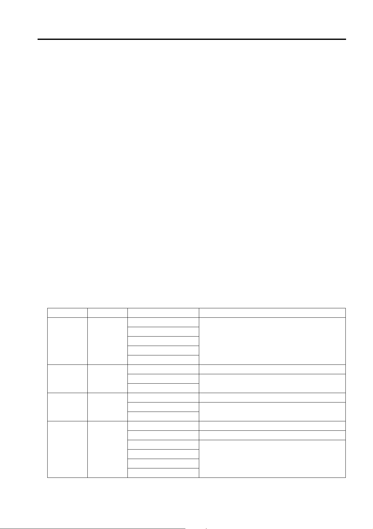
3. Electrical parts and signals
Those listed by way of example below are not exhaustive, but only some instances among many.
Classification Load symbol Ex. of signal name Description
IN
PS
Sensor PS
Solenoid SD
Clutch CL
Motor M
Door PS1
SIG
102 PS
24V Power to drive the solenoid
DRV
SOL
24V Power to drive the clutch
DRV
SOL
24V Power to drive the motor
CONT Drive signal
DRV1
DRV2
D1
D2
Sensor detection signal
Drive signal
Drive signal
Drive signals of two kinds
ix

Introduction
Classification Load symbol Ex. of signal name Description
_U
_V
_W
DRV1
DRV2
DRV3
D1
D2
D3
D4
DRV A
DRV A¯
DRV B
DRV B¯
Motor M
Others TH1.S, ANG Analog signal
Ground
Serial
communication
A
/A
B
/B
AB
BB
CLK, PLL PLL control signal
LCK, Lock, LD PLL lock signal
FR Forward/reverse rotation signal
EM, Lock, LCK, LD Motor lock abnormality
BLK Drive brake signal
P/S Power/stop
S/S
SS
CW/CCW, F/R Rotational direction switching signal
ENB Effective signal
TEMP_ER Motor temperature abnormality detection signal
SG, S.GND, S_GND Signal ground
PG, P.GND Power ground
DCD Data carrier detection
SIN Serial input
SOUT Serial output
DTR Data terminal operation available
GND Signal ground (earth)
DSR, DSET Data set ready
RTS Transmission request signal
CTS Consent transmission signal
RI Ring indicator
TXD Serial transmission data
RXD Serial reception data
KONICA MINOLTA 8050/CF5001/C500/8150 Field Service Ver.3.0 Dec. 2004
Drive signals (control signals) of three kinds
Drive signals (control signals) of four kinds
Motor, phases A and B control signals
Operating load start/stop signal
x
 Loading...