

Page 1
DRYPRO model 752
OPERATION MANUAL
LASER IMAGER
KONICA CORPORATION
No. 26-2, Nishishinjuku 1-chome, Shinjuku-ku, Tokyo 163-0512, Japan
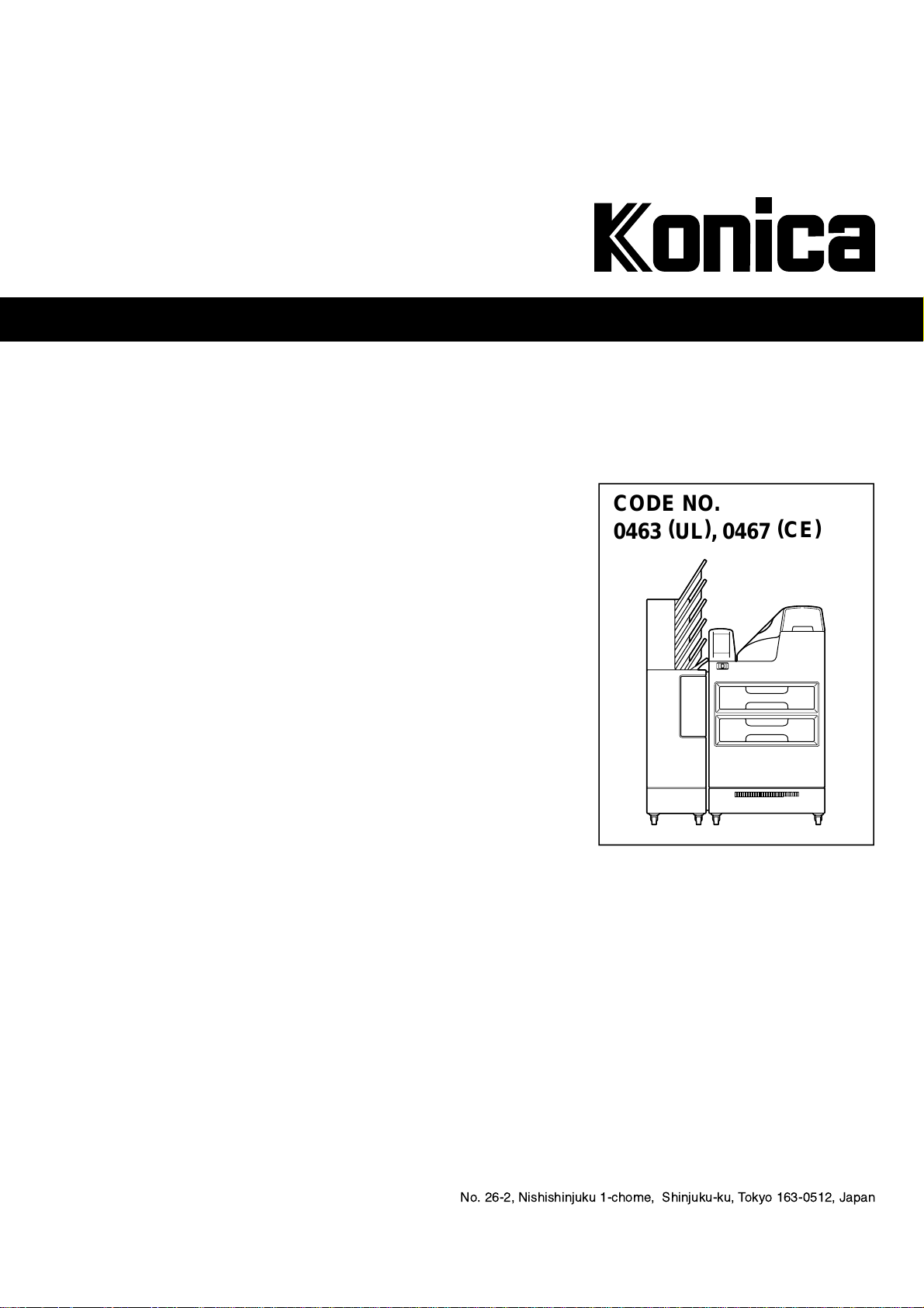
CODE NO.
0463 (UL), 0467
(CE)
Page 2

Blank page
Page 3
DRY LASER IMAGER DRYPRO MODEL 752
Table of Contents
Introduction................................................................................ ii
Descriptions of Symbol Mark.....................................................iii
Descriptions on Warning Label................................................. iv
Warning Label............................................................................ v
Warning Label Location............................................................ vi
Safety Caution ..........................................................................vii
Precaution..................................................................................x
1. Name of Each Component..................................................1
1-1. Main Body.....................................................................1
1-2. Sorter LiS-752 (option) ................................................3
2. Structure .............................................................................4
3. How To Operate...................................................................5
3-1. Control Panel ...............................................................5
3-2. Start-up Operation........................................................6
3-3. Shut-down Operation....................................................8
3-4. Film Loading...............................................................11
4. Maintenance Mode............................................................ 16
4-1. Function of Maintenance Mode ..................................16
4-2. Switching Maintenance Mode.....................................17
4-3. How To Operate Maintenance Mode ..........................18
5. Troubleshooting.................................................................47
5-1. Error Display and Remedy..........................................47
5-2. Resetting Errors.......................................................... 49
5-3. Removing Jam............................................................ 52
5-4. When Film Fails to be Loaded....................................61
6. Service and Maintenance.................................................. 65
6-1. Periodical Maintenance and Inspection......................65
6-2. Replacing FILTER.......................................................66
6-3. Service and Maintenance Schedule...........................67
7. Specifications....................................................................69
Appendix..................................................................................71
HANDLING AND STORAGE OF DRY FILM............................72
This device uses laser. Direct exposure of the laser
on the skin or in the eyes may lead to serious
injuries. And, high voltage may be applied on some
sections in the device. Be careful not to suffer an
electrical shock upon handling the device.
Be sure to observe the following in order to prevent any danger.
1. NEVER remove the external and internal covers with a screwdriver, and others.
2. NEVER perform any operations, adjustments, or actions other than the specified in this
Operation Manual; otherwise, you may be exposed to dangerous radiation.
3. If any problem occurs in this device, contact a service person. NEVER use the troubled
device as it is dangerous.
DRYPRO MODEL 752 Operation Manual Ver.0.11 2002.6 i
Page 4
•
•
Introduction
Thank you for purchasing Dry Laser Imager DRYPRO model 752.
The Dry Laser Imager DRYPRO model 752 makes all processing dried and improv es the en vironment and the
operability while maintaining high performance and high-quality images.
•
High-quality Image
µ
1) Realizing super-sharpened images with the pixel size of 40
2) Newly developing film that is most suitable for the imager and CR
3) Supporting 12-bit image input
4) Rendering high-quality images with advanced image interpolation processing technology
5) Installing the auto density control function for stabled image output
Operation environment
1) Shortening waiting time for output by high-speed processing capability (120 sheets / hour)
2) Simultaneously loading different sizes and types with the two trays
m (min.)
Imaging environment
Direct connection to diagnostic devices with DICOM communications function securing expandability on the open
network.
- Sorter LiS-752 is optional device.
ii DRYPRO MODEL 752 Operation Manual Ver.0.11 2002.6
Page 5
Descriptions of Symbol Mark
The meaning of following symbol marks described in this equipment and this manual is as the following table.
Symbol mark Descriptions of symbol mark
Attention
Consult accompanying document.
Protective earth (ground)
OFF (power: disconnection from the mains)
ON (power: connection to the mains)
ON (only for a part of equipment)
Alternating current
DRYPRO MODEL 752 Operation Manual Ver.0.11 2002.6 iii
Page 6
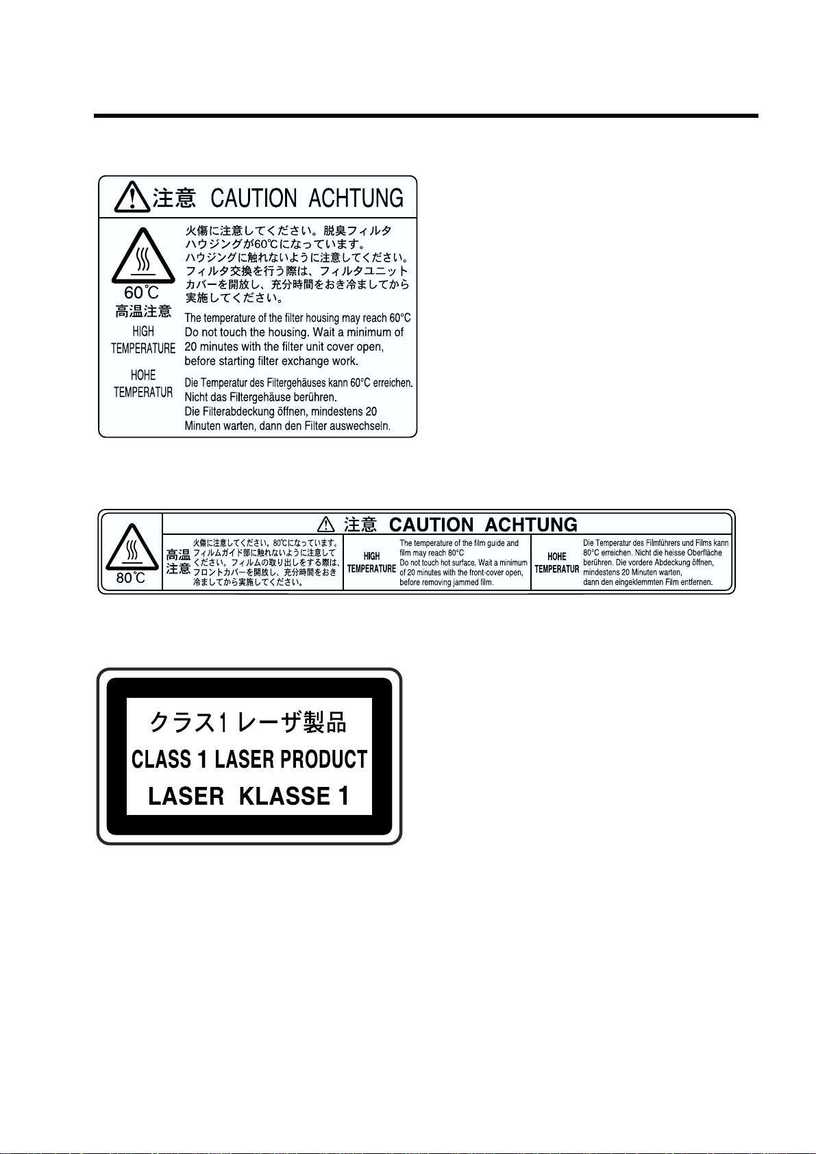
Descriptions on Warning Label
"
Descriptions on warning (caution label)
#
Caution labels imply the degree of the risk that may arise from incorrect use of this product.
#
There are three degrees of caution labels, and each is used depending on the level of risk and
damage caused by incorrect use and mishandling.
DANGER:
WARNING:
CAUTION:
Bodily injury
(and damage to
property)
If failed to avoid the risk, this implies the imminent danger level that may lead
to serious injury including a loss of life.
If failed to avoid the risk, this implies the danger level that may lead to serious
injury including a loss of life.
If failed to avoid the risk, this implies the danger level that may lead to
moderate damage or light injury. Also it is used when a physical damage
alone is expected.
Risk of Damage
High Low
Loss of life or serious
injury
(Damage is serious)
Moderate damage or
light injury
(Damage is light)
DANGER WARNING
WARNING or
CAUTION
CAUTION
Damage to property only CAUTION
[NOTE] : If the contents of this page are not legible, order a new manual.
iv DRYPRO MODEL 752 Operation Manual Ver.0.11 2002.6
Page 7
Warning Label
(1)
(2)
(3)
[NOTE] : If the contents of this page are not legible, order a new manual.
DRYPRO MODEL 752 Operation Manual Ver.0.11 2002.6 v
Page 8
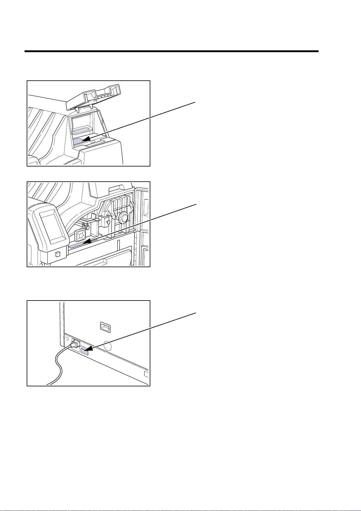
Warning Label Location
1) Front
(1)
2) Rear
(2)
(3)
[NOTE] : If the contents of this page are not legible, order a new manual.
vi DRYPRO MODEL 752 Operation Manual Ver.0.11 2002.6
Page 9
Safety Caution
Before operating this device, be sure to read Safety Caution.
Be sure to observe the safety cautions described here as they are very important for safety.
"
Cautions on installation
Never attempt to modify the device.
If you modify the device, this may cause a breakdown, electric shock, or fire.
For installation, contact a sales office where you purchased this device or
a service person.
If you install the device and there are any problems in installation, this may cause an electric shock or a fire.
Be sure to ground the device well.
Never connect the grounding cable to the gas pipe, water supply pipe, lighting rod, or the
grounding cable for telephone.
As for the electrical work (including grounding and communications cable
work) follow the local regulations on the technical standards.
If the work is not done properly, this may cause an electric shock or breakdown.
Use the power supply with sufficient capacities according to the specifications.
If you use any power supply other than the specifications, or the power supply with insuffi-
cient capacities, this may result in heating the electrical components or cause a fire.
"
Cautions on transporting, storing temporally, and servicing
If an abnormal sound, stench, or smoking occurs in this device, immediately turn the power OFF, then unplug the power cable. Contact a sales
office where you purchased this device or a service person.
If you continue using the troubled device, this may cause a breakdown, electric shock or
fire.
If any error other than the specified in this Operation Manual occurs, contact a service person.
If you repair it by yourself, and there are any problems on it, this may cause an electric
shock or fire.
When transporting, temporally storing, or re-installing this device, contact
a sales office where you purchased this device or a service person.
If you transporting or re-installing it by yourself, and there are any problems on it, this may
cause an electric shock or fire.
[NOTE] : If the contents of this page are not legible, order a new manual.
DRYPRO MODEL 752 Operation Manual Ver.0.11 2002.6 vii
Page 10
Safety Caution
"
Cautions on use
Never open or close any covers other than the specified in this Operation
Manual.
High voltage may be applied on some sections in the device. If you touch them accidentally, you may suffer burns or an electric shock.
When replacing FILTER or removing film jams in the discharge section,
follow the procedure in this Operation Manual;
otherwise, a fire may be caused.
When touching the LCD (glass) on the control panel, do not give a strong
mechanical impact; otherwise it may be damaged. If the LCD is damaged,
immediately contact a service person.
This cause a breakdown or injuries.
Plug the power cable completely.
If dust is accumulated on the power plug, or the power cable is not plugged properly, this
may cause an electric shock or a fire.
Be sure to use the power cable supplied with this device. Do not use an
extension cord or do not connect another device to the same wall outlet;
otherwise, a fire or heating may be caused.
Be careful not to trip over the power cable to damage it.
If you continue using the damaged power cable, this may cause an electric shock or fire.
Do not block the air intake or the air outlet of this device;
otherwise, a breakdown may be caused.
Do not start up or shut off the device by plugging or unplugging the power
cable;
otherwise, an electric shock or breakdown may be caused.
If it is likely that lightning may occur, stop operating the device, and unplug
the power cable.
A breakdown may occur depending on the degree of lightning.
Do not use this device for any purpose other than printing image data;
otherwise, a breakdown may be caused.
Do not operate the switches with wet hands;
otherwise, you may suffer an electric shock.
[NOTE] : If the contents of this page are not legible, order a new manual.
viii DRYPRO MODEL 752 Operation Manual Ver.0.11 2002.6
Page 11
Safety Caution
When unplugging the power cable, do not pull it;
otherwise, the inner cable may be broken, and this may cause heating or a fire.
Do not let this device exposed to water by cleaning the device with a wet
cloth or placing the vase containing water on the device, etc;
otherwise, you may suffer an electric shock due to a leakage of currents.
Before you clean the device, be sure to stop operating it, and unplug the
power cable or turn the breaker OFF;
otherwise, you may suffer injury or the device may be broken do wn as the f an rotates at the
high speed in the device.
If the device is not going to be used for an extended period of time, unplug
the power cable for safety purpose;
otherwise, dust may be accumulated, resulting in heating or a fire.
As for any servicing other than "Servicing by User" described in this Operation Manual, contact a service person as they require an expert technology.
If you perform any service other than "Servicing by User" by yourself, and there are any
problems on it, this may cause an electric shock or fire.
If the smell is unpleasant, install a ventilating fan in a room where this
device is installed.
(Please determine the size and capacity of the fan according to the structure of a room.)
Although a chemical substance is discharged during operation, the
amount of emissions is within acceptable limits.
[NOTE] : If the contents of this page are not legible, order a new manual.
DRYPRO MODEL 752 Operation Manual Ver.0.11 2002.6 ix
Page 12

Precaution
"
Disposal Precaution
When disposing the following used parts, accept the regulations of each
local government.
1)The DRYPRO 752 itself.
2)The packaging materials for DRYPRO 752.
3)The photosensitive materials used on the DRYPRO 752.
4)The lead and lithium batteries inside the DRYPRO 752, which can be
hazardous and must be disposed properly.
"
Precaution on Installation Location
Be sure to observe the following conditions for the installation location of
this device.
By installing this device in the Radiology Department, you could make the
work flow smooth.
1)Install the device in a location where it is not exposed to water.
2)Install the device in a location where it is not exceed the temperatures
or atmospheric pressure described in the specifications.
3)Install the device in a location where it is not exposed to direct sunlight.
4)Install the device in a flat place.
5)Install the device where there is no likelihood of being given by
vibration or impact.
6)Install the device in a location where there is no likelihood of being
adversely affected by chemical agents, or air containing gas, dust, salt
or sulfur, etc.
[NOTE] : If the contents of this page are not legible, order a new manual.
x DRYPRO MODEL 752 Operation Manual Ver.0.11 2002.6
Page 13
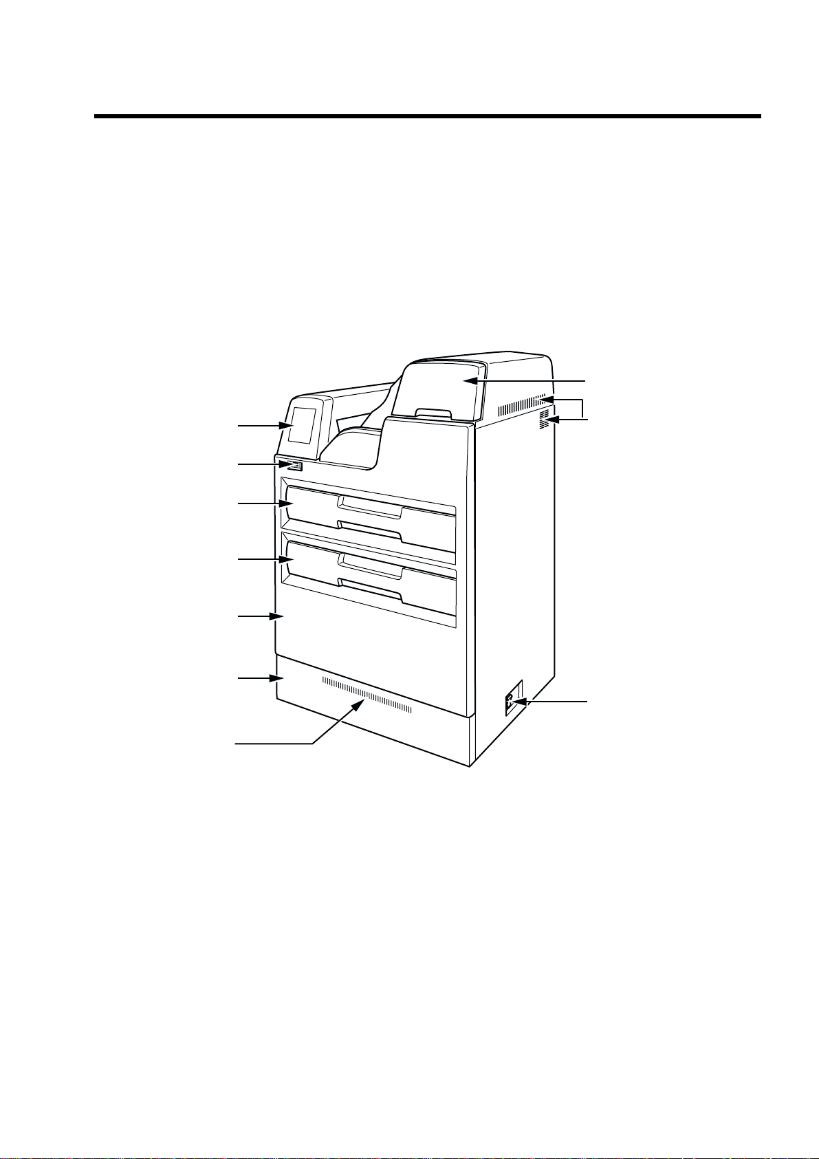
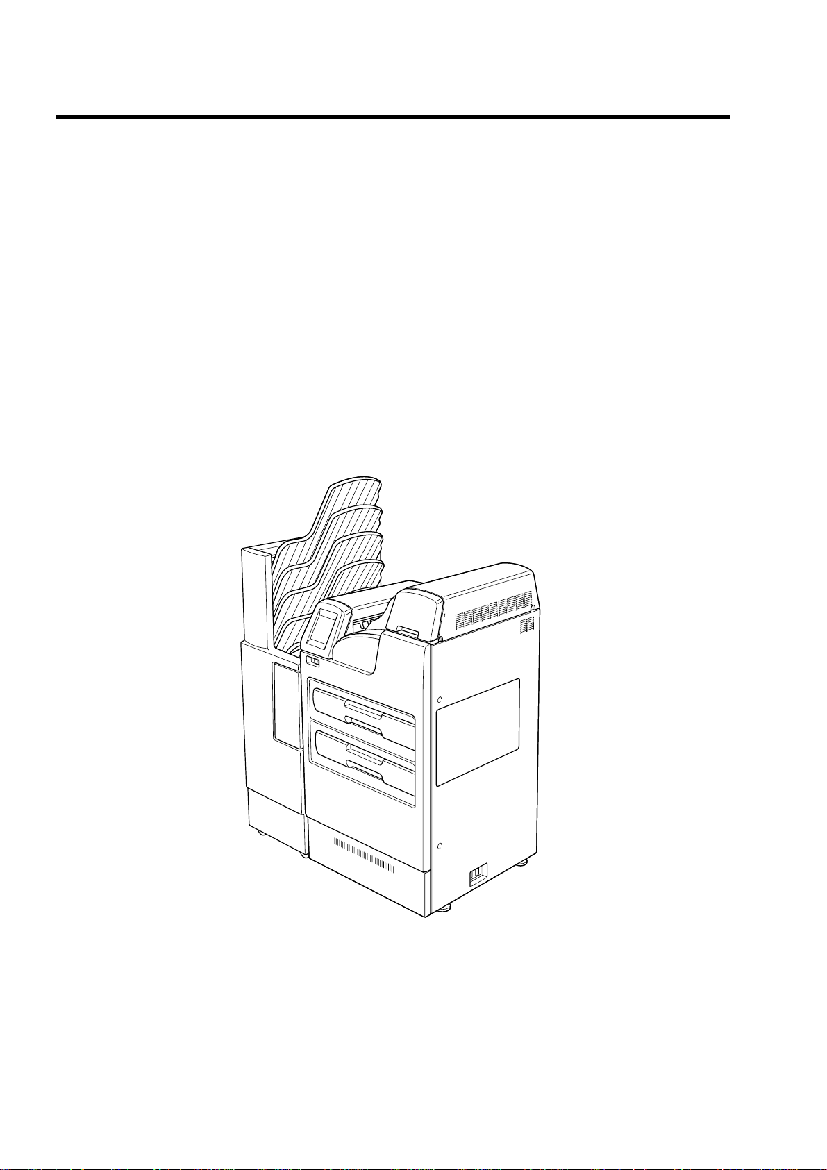
Control panel
Upper tray
Start switch
Lower tray
Front cover
Lower cover
Breaker
Filter unit cover
Air intake
Air intake
1. Name of Each Component
1-1.Main Body
"
Front Vie w
DRYPRO MODEL 752 Operation Manual Ver.0.11 2002.6 1
Page 14
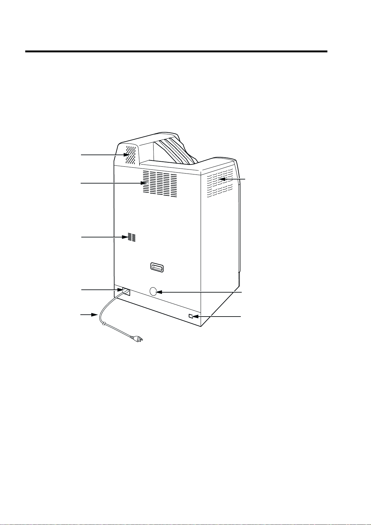
1-1.Main Body
"
Rear View
Air outlet
Air outlet
Air outlet
Power connector
Power cable
Air intake
Air outlet
Ethernet port (RJ45)
2 DRYPRO MODEL 752 Operation Manual Ver.0.11 2002.6
Page 15
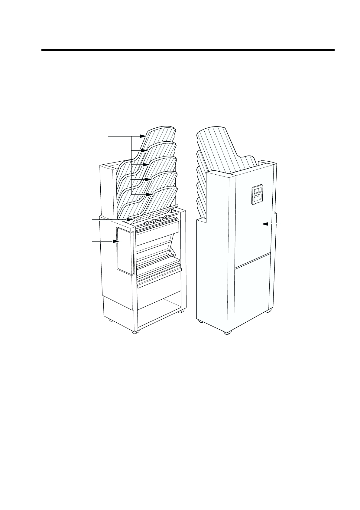
1-2.Sorter LiS-752 (option)
Sorter left cover
Front cover
Inlet guide
Bins
1-2.Sorter LiS-752 (option)
DRYPRO MODEL 752 Operation Manual Ver.0.11 2002.6 3
Page 16
2. Structure
(7)
(8)
(10)
(1)
(2)
(11)
(3)
- Sorter LiS-752 is optional device.
(1) Supply section
Picks up each sheet of film from the tray unit, and sends
to the descent transport section.
(2) Descent transport section
Sends the picked-up film in the supply section to the
position control section.
(3) Position control section
Aligns the film sent from the descent transport unit horizontally, and sends it to the exposure section.
(4) Exposure section (a: Subscan unit, b: Optical
unit)
Performs a laser scanning in synchronization with the
film transport and prints an image on the film.
(5) Elevator transport section
Sends the film to the HPRO (Heat Processing) section
after the exposure.
(6)
(5)
(4)
(9)
(6) HPRO (Heat Processing) section
Processes the exposed film by heating.
(7) Cooling/Discharge section
Cools the heat-processed film and discharges it.
(8) Air-cooling section
Remove the odor generated by heat-processing with a filter.
(9) Electrical control section
Consists of the power supply unit for supplying the power to the
device and the control unit for controlling the entire device,
communicating with the diagnostic devices, and processing /
controlling images.
By installing an optional battery for UPS (uninterruptible power
supply), the system in the control unit can be backed up even
though power failure occurs due to electrical accidents.
(10)Control panel
Operates and makes settings of the device.
(11)Sorter (option)
Discharges the film discharged from the main body into the
specified bin.
4 DRYPRO MODEL 752 Operation Manual Ver.0.11 2002.6
Ver.0.12 2002.7
Page 17
(2)
(11)
(8)
(4)
(9)
(7)
(5)
(1)
(3)
(12)
(10)
(13)
(6)
3. How To Operate
The operation, control and settings of this device can be made by using the control panel located on the main unit. The
following shows the operating procedures.
3-1.Control Panel
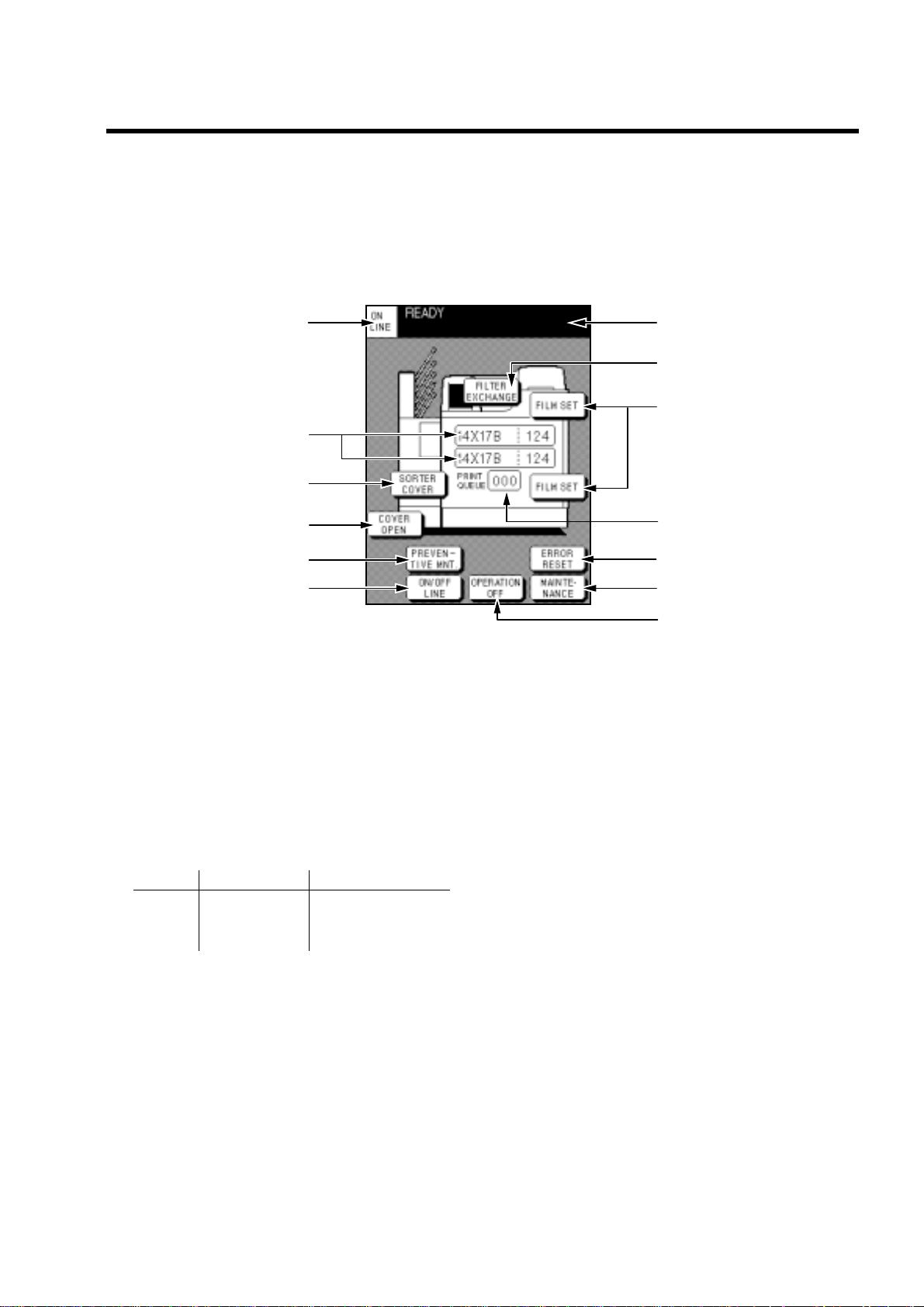
"
Description on screen
(1) ON LINE/OFF LINE Indication
Displays the ON LINE/OFF LINE status of the device.
(2) Message Column
Displays the status of the device.
READY. . . . . . . . . . Ready for print
PRINTING . . . . . . . In print process
WARMINGUP . . . . During warming-up
MAINTENANCE . . Maintenance mode
(3) Information of Loaded Film
Displays film type, size, number of remaining films in
the upper and lower trays respectively.
Size Film type No. of remaining films 14 x 17 B (SD-P) 0-125 14 x 14 C (SD-PC) 11 x 14 DRB (DR-P)
(4) PRINT QUEUE
Displays the number of films waiting to be printed.
(5) OPERATION OFF Key
(6) ON/OFF LINE Key
(7) MAINTENANCE Key
Turns the power OFF and stops the operation.
Switches connected/disconnected (ON LINE/OFF
LINE) to/from the diagnostic device for communications.
Switches to the maintenance mode to change the settings and perform the inspection. This key appears only
when the device is in the OFF LINE status. (Refer to
page 16 for details.)
(8) FILM SET / TRAY OPEN / CALIBRATION Key
The FILM SET key opens the tray when the film tray becomes
empty. (Refer to page 11 for details.)
The TRAY OPEN key opens the tray when a film jam occurs in
the tray. (For removing film jams, refer to page 52.)
The CALIBRATION key is displayed to prompt you to perform
density correction when [MESS] is selected in the WEEKLY
CALIBRATION settings. (Refer to page 24 for calibration.)
(9) ERROR RESET Key
Resets the device when an error occurs. This key appears only
when an error occurs. (Refer to page 49 for error reset.)
(10)COVER OPEN Key
Opens the front cover when film jams occur. This key appears
only when film jams occur. (For removing film jams, refer to
page 52.)
(11)FILTER EXCHANGE Key
This key appears when the FILTER has to be replaced. The procedure for replacing the FILTER appears. (For replacing the
FILTER, refer to page 66.)
(12)SORTER COVER Key
Displayed when a film jam occurs in the sorter (option). Displays the procedure for removing film jams. (For removing film
jams, refer to page 52.)
(13)PREVENTIVE MNT Key
Displayed when the periodical maintenance inspection period
comes. (Refer to page 67 for periodical maintenance inspection.)
DRYPRO MODEL 752 Operation Manual Ver.0.11 2002.6 5
Page 18
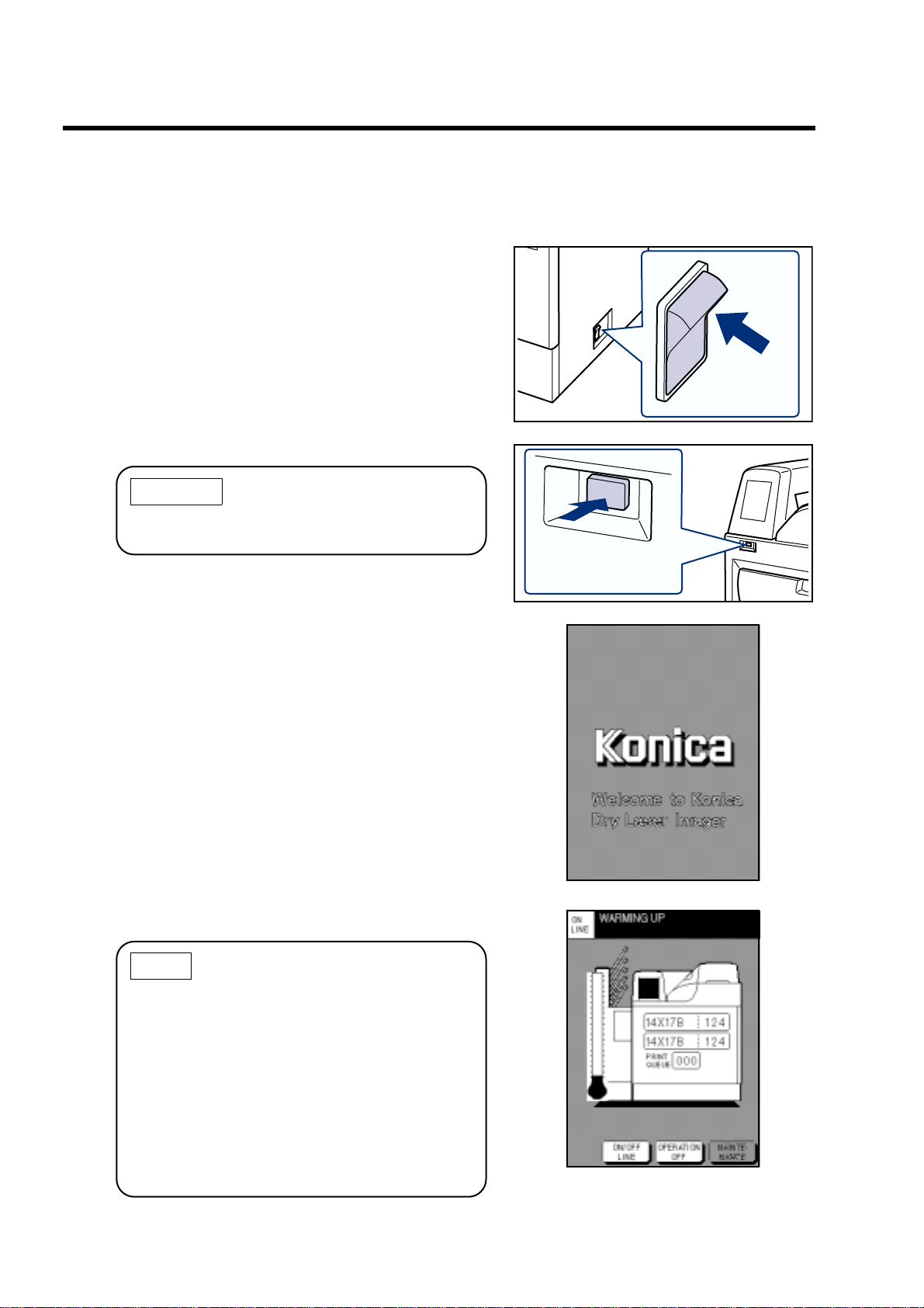
3-2.Start-up Operation
3-2.Start-up Operation
Follow the procedure below to turn on the power of the equipment.
(1) Turn ON the power of the breaker located at the
lower-right of the device.
Breaker
(2) Press the start switch below the control panel.
CAUTION
Pressing the start switch again turns OFF the
power. In this case, press the start switch again.
(3) The startup screen will appear.
Start switch
(4) The WARMING UP screen will appear in approx. 2
minutes.
NOTE
• Although printing cannot be made during
warming up, the data from the diagnostic
devices can be received. The received data
will be printed out after the device goes into
the READY status.
• Settings on the maintenance can be made
during warming up.
• It takes approx. 25 minutes for the device to go
to the READY status. Note that it depends on
temperature around the device.
6 DRYPRO MODEL 752 Operation Manual Ver.0.11 2002.6
Page 19
(5) When READY appears on the message column,
printing can be made.
NOTE
Use the START TIMER function to set the device
to READY on the specified time without pressing
the start switch.
(Refer to page 18 for details on how to set the
START TIMER function.)
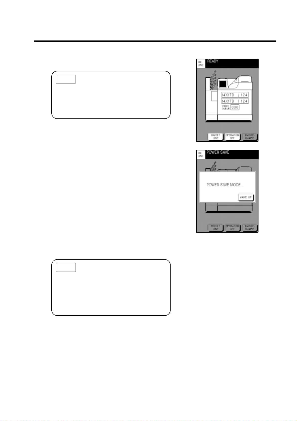
" Power saving mode
The DRYPRO has the power saving mode that saves
power consumption automatically after no data is
printed or no printing data is received for a specified
time.
When the DRYPRO goes into the power saving mode,
the screen on the right appears on the control panel,
and the backlight fades out. The power saving mode is
not enabled during OFF LINE mode.
The DRYPRO exits from the power saving mode and
starts warming up by performing the following operations.
• Touch [WAKE UP] on the control panel.
• When the DRYPRO receives printing data from a
diagnostic device, it exits from the power saving mode
automatically, and starts printing when it goes into the
READY status.
3-2.Start-up Operation
NOTE
• The time period ov er which the DRYPRO goes
into the READY status depends on the power
saving mode levels.
•You can set Use/Disuse or the level of the
power saving mode on the MAINTENANCE
MENU screen. (Refer to page 45.)
DRYPRO MODEL 752 Operation Manual Ver.0.11 2002.6 7
Page 20
3-3.Shut-down Operation
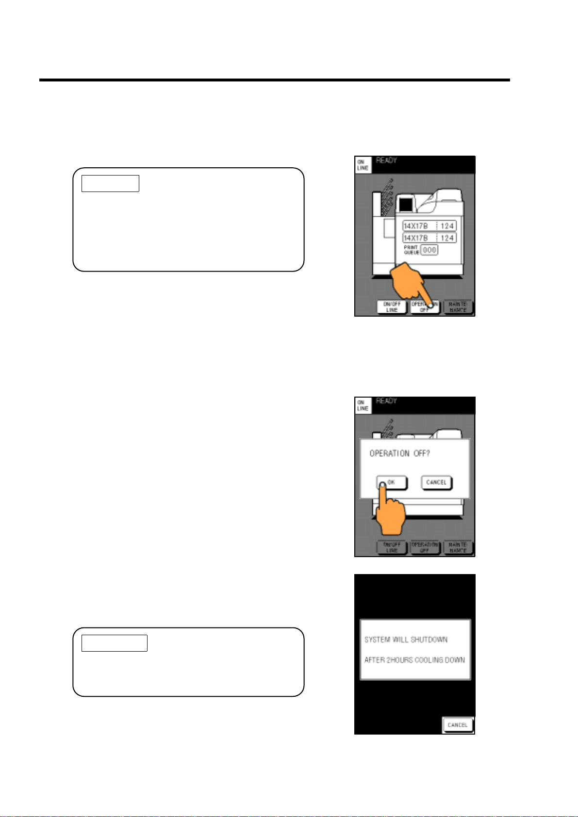
3-3.Shut-down Operation
Following the procedure below to shut down the device.
(1) Touch [OPERATION OFF] on the control panel.
CAUTION
Be sure to check that PRINT QUEUE shows
"000" before performing the shut-down operation.
If you shut down the device when PRINT Q UEUE
shows any number other than "000", the remaining data that has not printed yet will be printed
out next time the device starts up.
(2) The confirm screen of OPERATION OFF appears.
Different confirm screens appear when the START TIMER is
set to ON and when not set.
• When START TIMER is not set to ON;
If START TIMER is not set to ON, when you touch [OPERATION OFF] on the normal screen, the confirm screen on the
right appears.
(1) Touch [OK] to perform OPERATION OFF, then the
message shown on the lower-right appears.
Touching [CANCEL] will go back to the normal screen.
(2) The device will be shut down in approx. 2 hours,
and the display on the control panel will go off.
The FILTER fan functions for approx. 2 hours until the HPRO
(heat processing) section is cooled down. During that time, the
backlight of the control panel fades out.
IMPORTANT
When you need to print out some data during
shut-down operation, touch [CANCEL] to go back
to the normal screen.
8 DRYPRO MODEL 752 Operation Manual Ver.0.11 2002.6
Page 21
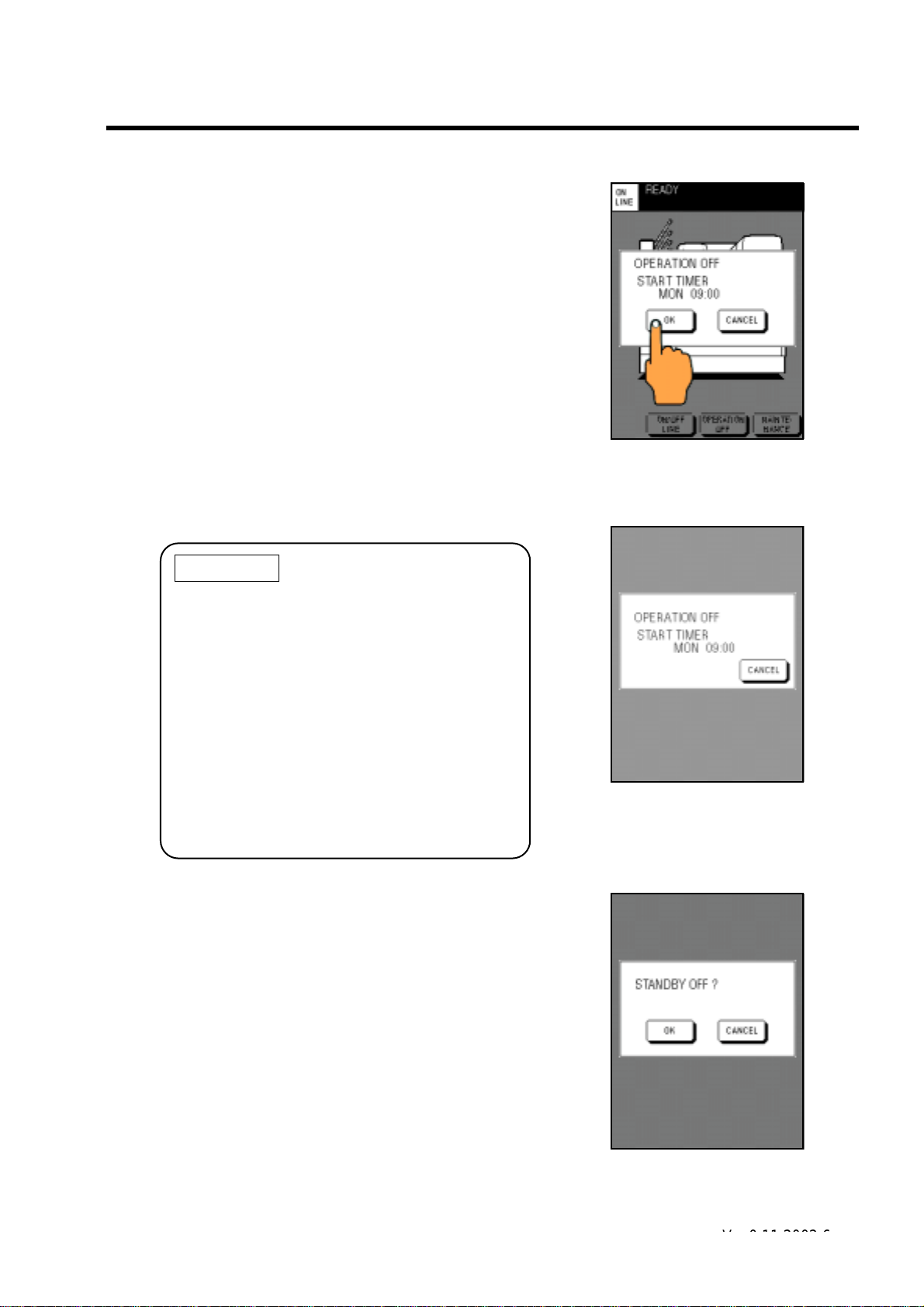
• When START TIMER is set to ON;
Operation OFF message
(Start Timer ON)
Standby mode message
Restart confirm message
If START TIMER is set to ON, when you touch [OPERATION
OFF] on the normal screen, the time at which the DRYPRO
goes into the READY status for the next time appears on the
confirm screen on the right.
(1) Touch [OK] to perform OPERATION OFF proce-
dure.
Touching [CANCEL] will go back to the normal screen.
When START TIMER is set to ON, the de vice will not turn of f,
and go into the standby mode.
In the standby mode, the backlight of the control panel fades
out with the time to go to READY for next time displayed.
[CANCEL] will appear after a lapse of certain time after the
device goes into the standby mode.
3-3.Shut-down Operation
IMPORTANT
•Touch [CANCEL] on the screen on which the
standby mode message appears if you wish to
make printing in the standby mode. The confirm message on the lower-right appears,
touch [OK] to restart the device.
• [CANCEL] will appear after a lapse of certain
time (approx. 2 minutes) after the device goes
into the standby mode.
•When you use the START TIMER function,
leave the breaker of the device ON after
OPERATION OFF procedure is made. (Refer
to page 18 for details on how to set the START
TIMER function.)
DRYPRO MODEL 752 Operation Manual Ver.0.11 2002.6 9
Ver.0.12 2002.7
Page 22

3-3.Shut-down Operation
CAUTION
•When the power turns OFF even though you
set the START TIMER to ON, there is a possibility that a power failure may occur during the
standby mode.
Press the start switch to re-start the equipment.
• If a power failure occurs during the standby
mode, the message for showing the occurrence of a power failure appears on the Startup screen.
Power failure message
10 DRYPRO MODEL 752 Operation Manual Ver.0.11 2002.6
Page 23
3-4.Film Loading
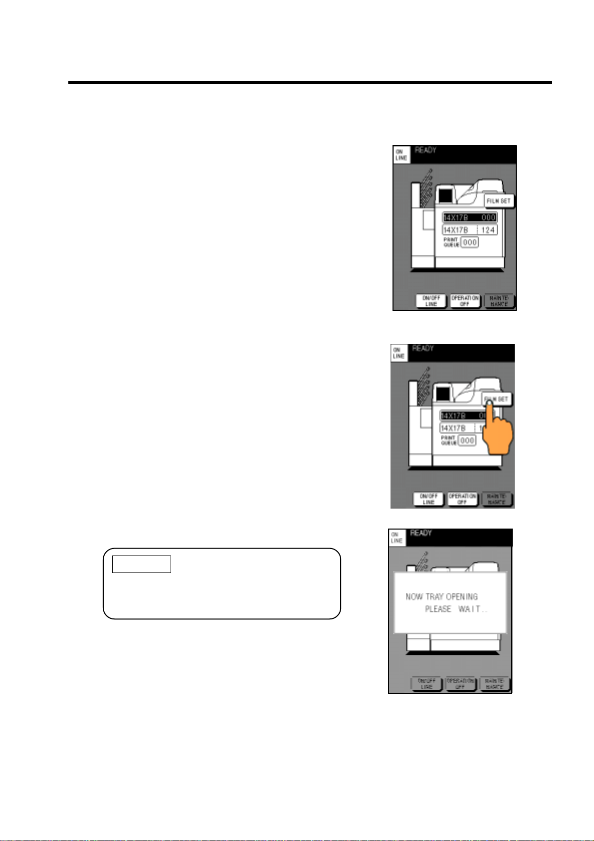
When the tray becomes empty, "FILM EMPTY" appears
and [FILM SET] is displayed on the right of the loading
film information of the empty tray.
The screen on the right shows that the upper tray
becomes empty.
• The film size for this device can be selected from
14"x17", 14"x11", and 14"x14". The film size for each
tray is set by a service person at installation.
• It is possible to receive print data from the diagnostic
device while the film is loaded.
Follow the procedure below to load the film.
(1) Touch the displayed [FILM SET].
The message showing the tray being opened appears.
3-4.Film Loading
Then, the empty tray pops out slightly, and the screen showing
the procedure for loading the film (next page) is displayed.
CAUTION
If a film is in print process, the cover will not open
until the printing completes. It will take max. 95
seconds.
DRYPRO MODEL 752 Operation Manual Ver.0.11 2002.6 11
Message for tray being opened
Page 24
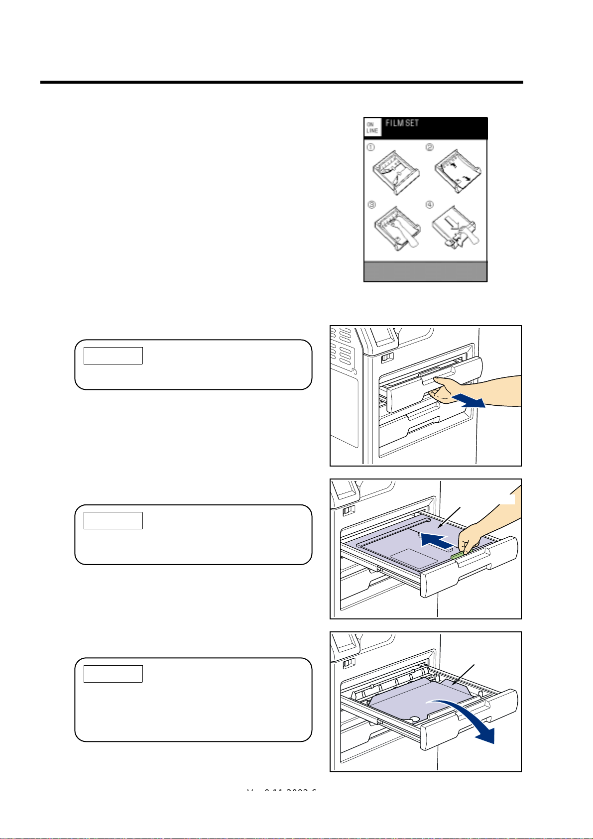
3-4.Film Loading
(2) Slowly pull out the opened tray as far as it goes.
CAUTION
Film loading screen
Do not place anything on the opened tray.
(3) Hold the handle (green par t) of the tray and open
the light shield cover fully.
CAUTION
The light shield cover of the tray cannot be
opened unless the tray is pulled out completely.
(4) Remove the resin tray and the empty film package
that remain in the tray.
CAUTION
Light shield cover
Resin tray
When disposing of the resin tray and the empty
film package, they should be treated as industrial
wastes. Dispose of them following the regulations of your institution.
12 DRYPRO MODEL 752 Operation Manual Ver.0.11 2002.6
Ver.0.12 2002.7
Page 25
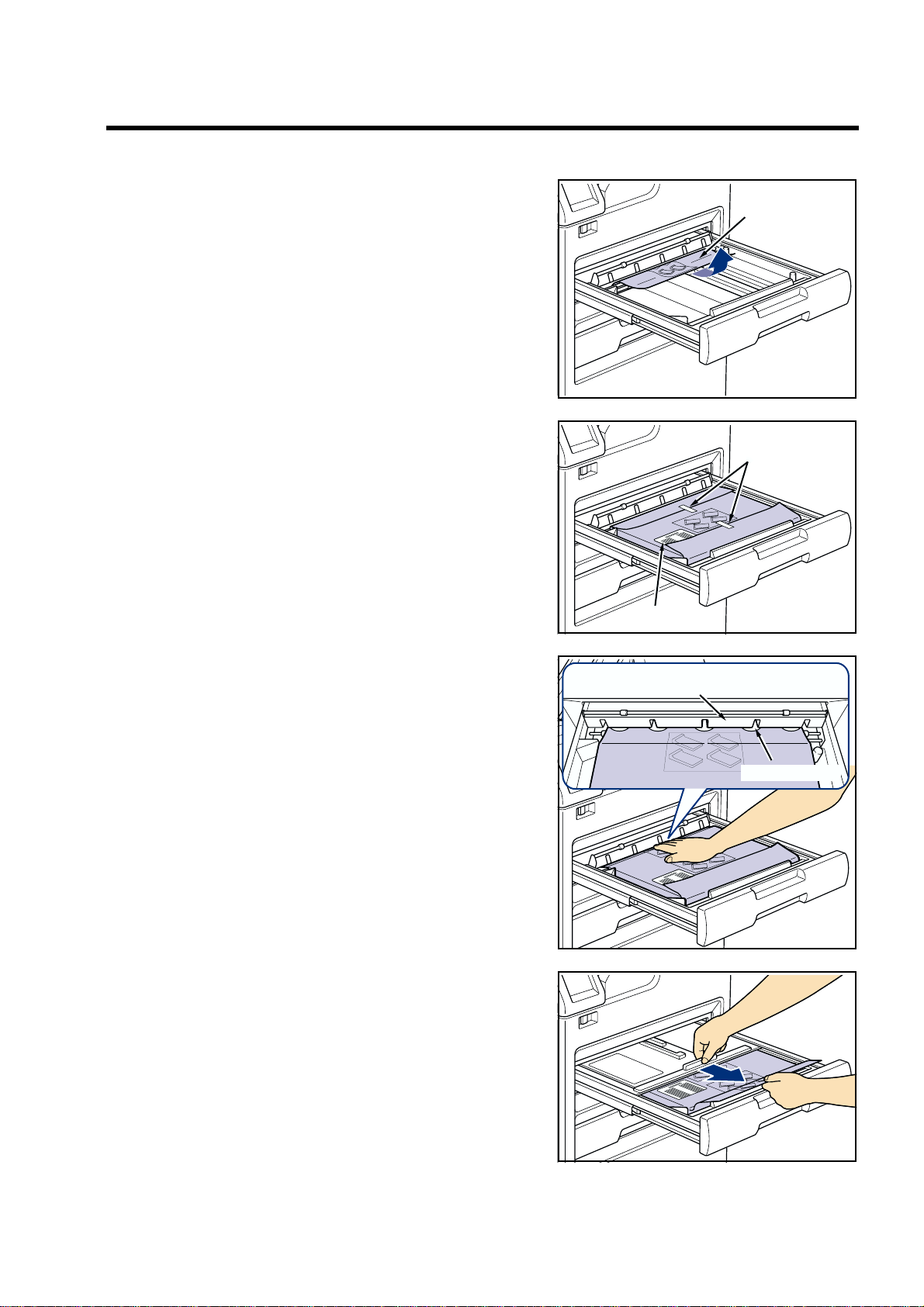
(5) Load the package of new film so that the barcode
Empty package
Seals
Barcode
Retaining plate
Taking-up shaft
comes at the front-left position, and peel off the
seals at the edges of the package.
3-4.Film Loading
(6) Insert the back of the package between the retain-
(7) Close the light shield cover completely so that the
ing plate and the taking-up shaft firmly.
front of the package lies off the cassette.
DRYPRO MODEL 752 Operation Manual Ver.0.11 2002.6 13
Page 26
3-4.Film Loading
(8) Cut off the front of the package that lies off the cas-
sette with the supplied cutter.
CAUTION
Put the cutter after use into the pocket on the
right-front of the tray for storage.
(9) Push the tray to the back until it is locked.
When the tray goes into the back completely, the message
appears.
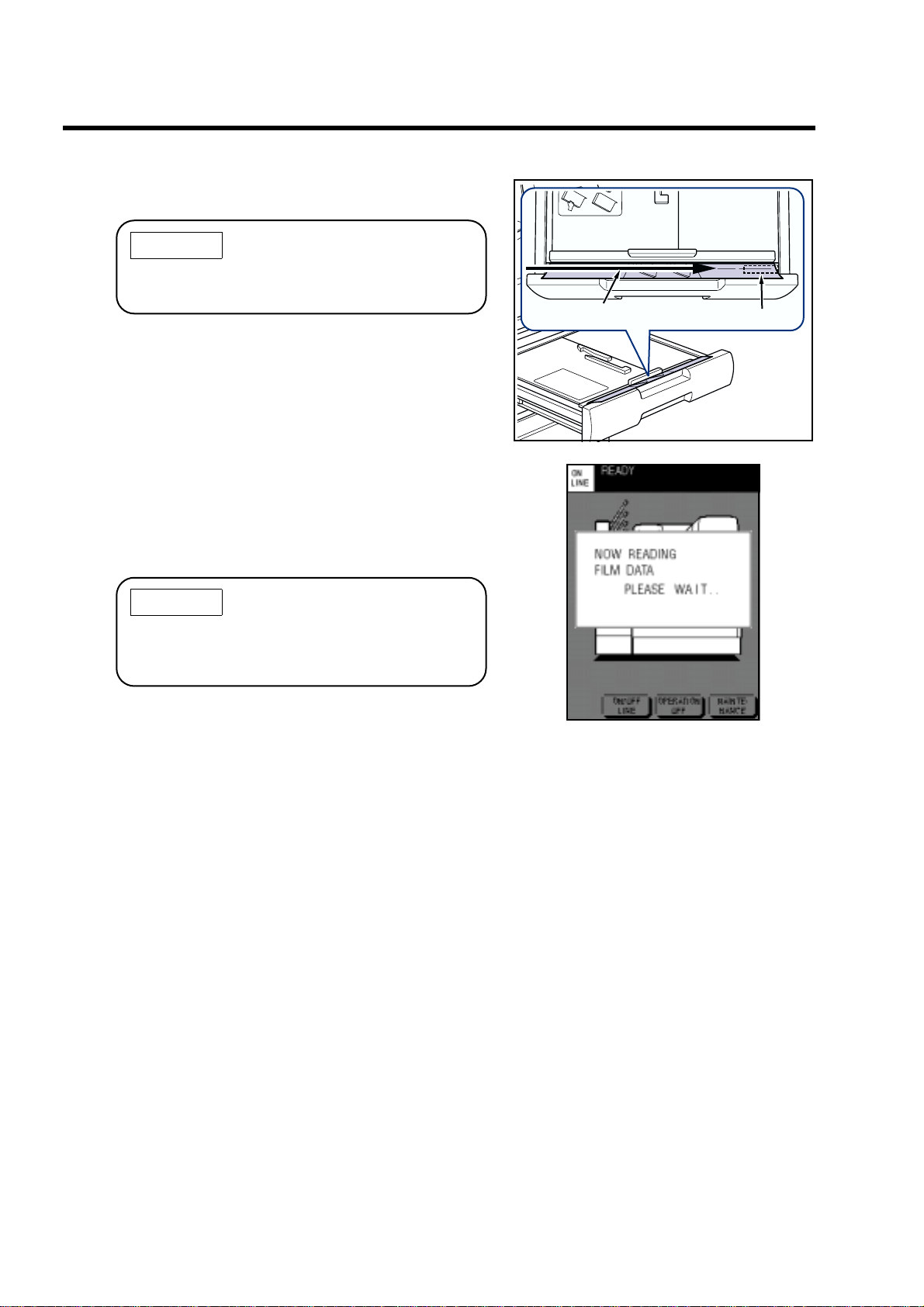
Then, the message of NOW READING FILM D ATA (barcode)
of the film package appears.
After reading the barcode is complete, the film of the calibration pattern for the auto density correction is discharged.
Cut off.
Pocket
CAUTION
If some films are queued, the automatic calibration is performed, but if no film is queued, the
automatic calibration is not performed.
Film data reading message
14 DRYPRO MODEL 752 Operation Manual Ver.0.11 2002.6
Page 27
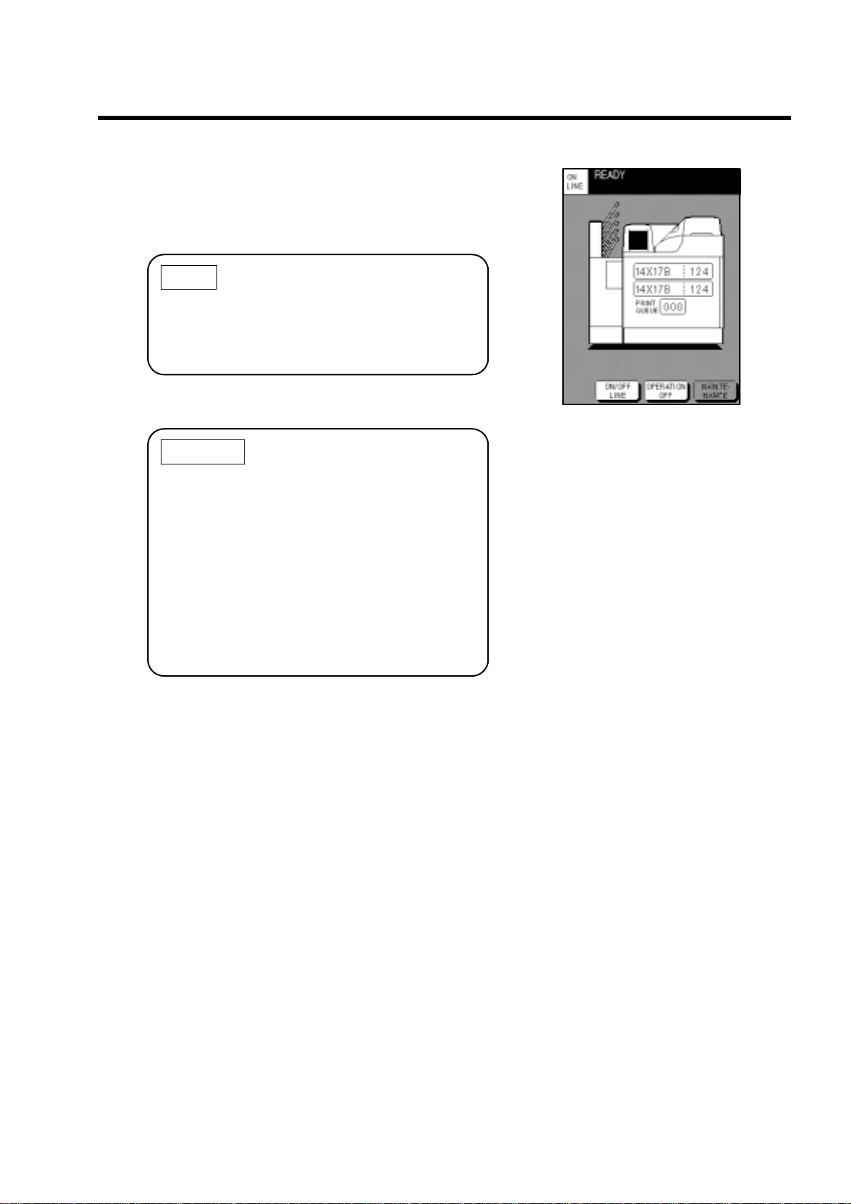
(10)The normal screen re-appears after the auto den-
sity correction, and print operation can be made. As
the data of the film that has been loaded newly is
displayed, verify the film size, type, and the number
of films.
NOTE
If the other tray is also empty, when you load the
film in one tray and close it, the other tray pops
out automatically.
Load the film by referring to Steps (2) or later.
CAUTION
• If you fail to cut off the film package, the barcode cannot be read and "FILM SET" is displayed again.
Open the tray again, and cut off the edge of
the package.
3-4.Film Loading
• If the first film cannot be picked up properly
because the package cannot be taken up correctly or other reasons, the error message
appears. In this case, remedy by following "5-
4. When Film Fails to be Loaded". (Refer to
page 61.)
DRYPRO MODEL 752 Operation Manual Ver.0.11 2002.6 15
Page 28

4. Maintenance Mode
4-1.Function of Maintenance Mode
This device has the maintenance mode that executes maintenance functions.
Touching [MAINTENANCE] on the control panel on OFF LINE will switch into the maintenance mode
and display the maintenance screen on the control panel.
In addition to the maintenance operations, the START TIMER function can be set, and re-printing of the
data that has already been printed can be made, etc.
• The print data from the diagnostic device cannot be received or printing cannot be made in the mainte-
nance mode.
The following shows the maintenance items that can be selected/executed in the maintenance mode.
No. Display Description
1START TIMER
2 TIME SET
3 PREVIOUS PRINT
4 CALIBRATION
5 TEST PRINT
6COVER OPEN
7PANEL ADJUST
8QUEUE CLEAR
9 COLD START
10 FILM DATA
11 PRINT CONDITION
12 USER LUT
13 FILMSET RETRY
14 POWER SAVE
Sets the START TIMER function to ON/OFF, and sets the start-up time for each day.
The START TIMER screen will appear. (Refer to page 18.)
Sets the time of the clock of the device. The TIME SET screen will appear.
(Refer to page 19.)
Re-prints the saved data that has been already printed out (PREVIOUS data).
The PREVIOUS PRINT screen will appear. (Refer to page 20.)
Prints the calibration sheet and corrects the density on the film. (Refer to
page 24.)
Prints out the SMPTE pattern to control the density.
The TEST PRINT screen will appear. (Refer to page 26.)
Open the front cover. (Refer to page 30.)
Adjusts the LCD contrast, the brightness of the backlight, and the touch area
in the touch panel.
The PANEL ADJUST screen will appear. (Refer to page 31.)
Clears the data queued in the device that has not been printed yet.
The QUEUE CLEAR screen will appear. (Refer to page 33.)
Cold-starts (re-start) the device. (Refer to page 35.)
CAUTION When the device is re-started b y COLD START, all
of the print data queued for printing and the saved
data that has been already printed out will be
deleted.
Confirms the sum of film. Sets the types of film to be counted, and date on
which film is counted. (Refer to page 36.)
Sets the print preferences for each of the connected diagnostic devices. (Refer to page 38.)
Creates user's own LUT curve, and applies it to the diagnostic device. (Refer to page 43.)
Used when the film fails to be loaded. (Refer to page 61.)
CAUTION Do not use this mode under the nor mal operation
as the number of films in the tray resets to 0.
Sets the power saving function of the device. (Refer to page 45.)
CAUTION
The print data from the diagnostic device cannot be received or printing cannot be made in the
maintenance mode. The print data queued for printing will be printed out after the device exits
from the maintenance mode.
16 DRYPRO MODEL 752 Operation Manual Ver.0.11 2002.6
Page 29

4-2.Switching Maintenance Mode
" Start-up maintenance mode
(1) Touch [ON/OFF LINE] on the normal screen to
switch into OFF LINE.
ON LINE displayed on the upper-left corner of the screen
changes to OFF LINE, and [MAINTENANCE] appears on the
lower-right corner of the screen.
(2) Touch [MAINTENANCE].
The maintenance menu (MAINTENANCE) screen listing the maintenance items appears.
4-2.Switching Maintenance Mode
CAUTION
When touching [MAINTENANCE] during print,
"NOW PRINTING PLEASE WAIT" is displayed
and the maintenance screen does not appear
until the printing operation is complete.
The data queued for printing will be printed out
after the device exits from the maintenance
mode.
(3) Touch the key of an item to execute.
The set screen or messages that correspond to the selected item
appears.
For details on how to operate each maintenance item, refer to
the following pages.
" Shut-down maintenance mode
Touching [EXIT] on the maintenance menu screen will exit the device from the maintenance mode, and return to
the normal screen.
• When the normal screen re-appears, touch [ON/OFF LINE] to go back to OFF LINE.
• When PREVIOUS PRINT, CALIBRATION, or TEST PRINT is set, the pint data for those will be printed
out after the device exits the maintenance mode.
DRYPRO MODEL 752 Operation Manual Ver.0.11 2002.6 17
Page 30

4-3.How To Operate Maintenance Mode
4-3.How To Operate Maintenance Mode
" Setting START TIMER Function
Setting the START TIMER function will start up the device from the Standby status automatically, and make it
into READY on the specified time. Setting the START TIMER function to ON/OFF, and the start-up time can be
made for each day.
Follow the procedure below to set the START TIMER.
(1) Touch [START TIMER] on the maintenance menu
screen.
The START TIMER screen will appear.
The key on the right of each day shows the ON/OFF of the
START TIMER.
"H" and "M" on the right of those keys show the hour and
minute for start time.
(2) Touch [ON] on the right of [START TIMER] to acti-
vate the START TIMER function.
Touching [OFF] clears the START TIMER function.
The selected key will be highlighted.
The key on the right of each day shows the ON/OFF of the
START TIMER.
(3) Touch the key on the right of each day on which you
wish to start the device automatically to display ON.
Touching the key again displays [OFF].
(4) When setting the time , touch H (hour) or M (min ute)
on the right of each day, then touch [$] / [%].
(5) After the settings are complete, touch [OK].
The setting becomes valid, and the maintenance menu screen
re-appears.
When you touch [CANCEL], the maintenance menu screen reappears without registering the settings.
IMPORTANT
When you set the START TIMER function to ON,
leave the breaker of the device ON.
18 DRYPRO MODEL 752 Operation Manual Ver.0.11 2002.6
Page 31

4-3.How To Operate Maintenance Mode
" Setting Date/Time (TIME SET)
Follow the procedure below to set the date and time for the clock in the device. Set the time zone and the use/
disuse of the summer time depending on the areas in which you use the device. Follow the procedure below to
make settings.
(1) Touch [TIME SET] on the maintenance menu
screen.
The TIME SET screen will appear.
The keys of DATE on the TIME SET screen show the date (D),
month (M), and year (Y) that are currently set.
The keys of TIME show the current time (hour (H) and minute
(M)).
(2) Touch the item key to be changed when setting the
date/time.
The selected key will be highlighted.
(3) Touch [$] / [%] to change the value.
The month (M) key shows each month in abbreviation (JAN to
DEC) every time you touch the [$] / [%] key.
(4) Confirm that "64" is displayed next to TIME ZONE.
"64" is code No. of time zone of Japan.
If any number other than "64" appears, display code No. "64"
next to TIME ZONE by touching [$] / [%].
For details on the area and code No. of time zone, refer to
Appendix at the end of this manual (page 71).
(5) Confirm that [OFF] next to SUMMER TIME is high-
lighted.
If [OFF] is not highlighted, touch [OFF] to highlight.
(6) After the settings are complete, touch [OK].
The setting becomes valid, and the maintenance menu screen
re-appears.
When you touch [CANCEL], the maintenance menu screen reappears without registering the settings.
DRYPRO MODEL 752 Operation Manual Ver.0.11 2002.6 19
Page 32

4-3.How To Operate Maintenance Mode
" Re-printing Printed Page (PREVIOUS PRINT)
In this device, as the data that has already been printed is stored in the inner hard disk, re-printing can be made
later. In this case, it is possible to change the print preferences such as the LUT applied for printing, print density,
and contrast, etc.
Follow the procedure below to re-print.
NOTE
The print data in the device is stored for each diagnostic de vice . The page number is assigned to
each print data in order in which it is received from the diagnostic device and printed out. (The
page No. is printed on the upper part of the film as the film management information.)
Page No.Film management information
1 0 0 1 P 300 20 32768 662 115301771170003 1,0R01 CH1:REGIUS_350 PAGE:4
(1) Touch [PREVIOUS PRINT] on the maintenance
menu screen.
The PREVIOUS PRINT screen (diagnostic device select
screen) will appear.
The names of the connected diagnostic devices are listed on the
diagnostic device select screen.
(2) Touch the name of the diagnostic device from
which the print data is received to print.
The selected diagnostic device name will be highlighted.
When 10 or more diagnostic devices are connected, touch [$] /
[%] to scroll the list of the diagnostic device names.
(3) Touch on the upper part of the screen.
The print page set screen will appear.
20 DRYPRO MODEL 752 Operation Manual Ver.0.11 2002.6
Page 33

(4) Touch the box on the right of [PAGE NO], and input
page No. that you wish to re-print.
In order to input the page No., touch the box on the right of
[PAGE NO.], then touch the numeric key on the lower portion
of the screen.
If you input the number incorrectly, touch [C] to clear it, and
input again.
(5) Touch the box on the right of [COPY] and input the
print count.
The procedure for inputting the print count is the same as the one for inputting the page No.
(6) If you print under the previous print conditions, con-
firm that [OFF] on the right of [CHANGE CONDITION] is selected, and touch [STORE].
The print data on the specified page will be queued.
If the specified page has been already deleted, "PREVIOUS
PAGE ERROR" is displayed.
CAUTION
4-3.How To Operate Maintenance Mode
The page specified on the PREVIOUS PRINT
screen will be printed out after the device exits
from the maintenance mode.
CAUTION
The amount of data that can be saved in the
device is about 100 pages.
When the storage becomes full, the data is
erased in order in which it is stored.
(7) Touch [ON] on the right of [CHANGE CONDITION]
when you print under different conditions from the
previous ones.
The LUT select screen will appear.
DRYPRO MODEL 752 Operation Manual Ver.0.11 2002.6 21
Page 34

4-3.How To Operate Maintenance Mode
(8) Touch a LUT name you wish to apply for printing.
The selected LUT name will be highlighted.
(9) Touch on the upper part of the screen.
The print preference set screen (2/3) will appear.
(10)Touch the key on the right of the setting item, then
touch [$] / [%] to set the following items.
DENSITY : Adjust the density of an image.
Selectable from -7 to 7.
Setting a negative value will make the den-
sity lighter, and a positive value, darker.
CONTRAST : Adjust the contrast of an image.
Selectable from -7 to 7.
Setting a negative value will make the con-
trast lower, and a positive value, higher.
SMOOTH TYPE : Sets the smoothing type of an image.
SMOOTH TYPE Settings
OFF Does not perform the magnification
interpolation.
1 Performs the Biliner interpolation.
2-6 Performs the Cubic Spline interpo-
lation.
Increasing the value will smooth an
image greater.
7 Does not perform the magnification
interpolation. But prints out in the
MAGNIFICATION setting. When
you wish to change this setting, ask
a service person.
22 DRYPRO MODEL 752 Operation Manual Ver.0.11 2002.6
Page 35

(11)Select NEGA/POSI by touching [NEGA] or [POSI].
(12)Touch on the upper part of the screen.
The print preference set screen (3/3) will appear.
(13)Touch the key on the right of the setting item, then
touch the numeric keys to set the following items.
MAX DENSITY : Sets the maximum density of an image.
MIN DENSITY : Sets the minimum density of an image.
Lo : (Not used for the current version.)
La : (Not used for the current version.)
SORTER : Sets the bin in the sorter (option) into
which the film is discharged.
4-3.How To Operate Maintenance Mode
(14)Touch [STORE].
The printing data on the specified page will be queued and the
print page set screen will re-appear.
If the specified page has been already deleted, "PREVIOUS
PAGE ERROR" is displayed.
(15) If there are other data to be printed, repeat from
Step (4) to set the print page.
If you wish to print the data from another diagnostic device,
touch to display the PREVIOUS PRINT screen, and
repeat from Step (2).
(16)To complete the settings of re-printing, touch [EXIT]
to return to the MAINTENANCE MENU screen.
(17)Touch [EXIT] to end the maintenance mode.
When the normal screen re-appears, the data on the specified
page will be printed out.
DRYPRO MODEL 752 Operation Manual Ver.0.11 2002.6 23
Page 36

4-3.How To Operate Maintenance Mode
" Calibrating Density (CALIBRATION)
The device has the densitometer in the cooling/discharge section, which allows you to control the density
automatically.
If there is a problem with the density, print the calibration sheet from this screen to calibrate the density.
• Calibration
(1) Touch [CALIBRATION] on the maintenance menu
screen.
The message for selecting the tray will appear.
(2) Touch the key of the tray for which you wish to per-
form density correction.
The print data in the calibration sheet will be queued, and the
maintenance menu screen will re-appear.
If you wish to perform density correction for the other tray, repeat from Step (1).
(3) Touch [EXIT] to end the maintenance mode.
When the normal screen re-appears, the film in the selected
tray is transported and the calibration sheet is printed out. Wait
until printing is complete. After printing is end, the density cor rection is complete.
IMPORTANT
• The calibration sheet is used as the sampling
data (the data before the density correction)
for the automatic density correction.
When you check and control the density, use
the SMPTE pattern which is printed out by
TEST PRINT on the maintenance menu.
(Refer to page 26.)
24 DRYPRO MODEL 752 Operation Manual Ver.0.11 2002.6
Page 37

• Automatic calibration
The DRYPRO has the automatic density calibration function
that perform the density calibration automatically after a lapse
of the specified time or specified number of printing. (Instead of
performing automatic calibration, you can make [CALIBRATION] appear on the screen to show you that the calibration
needs performing depending on the settings at installation.)
Or the automatic density calibration can be performed when the
film is loaded.
CAUTION
•Even after a lapse of the specified period or
specified number of printing, the automatic
calibration is not performed if printing data is
not queued. The automatic calibration is performed when the printing data is queued after
a lapse of the specified period or specified
number of printing.
• The automatic calibration is performed if the
printing data is not queued even when the film
is loaded. The automatic calibration is performed when the printing data is queued on
the next time.
4-3.How To Operate Maintenance Mode
DRYPRO MODEL 752 Operation Manual Ver.0.11 2002.6 25
Page 38

4-3.How To Operate Maintenance Mode
" TEST PRINT
Follow the procedure below to print out the SMPTE pattern in the device used for density control. Follow the
procedure below to print out.
• How to print out
(1) Touch the [TEST PRINT] key on the maintenance
menu screen.
The message for selecting the tray will appear.
(2) If you print under the previous print conditions,
touch the key of the tray in which film to be used is
loaded.
The confirm screen will appear. (Proceed to Step (13).)
(3)
Touch [CONDITION SET UP] when you print under
different conditions from the previous ones.
The TEST PRINT CH screen (diagnostic device select screen)
will appear.
The names of the connected diagnostic devices are listed on the
diagnostic device select screen.
26 DRYPRO MODEL 752 Operation Manual Ver.0.11 2002.6
Page 39

(4) Select the diagnostic device name you wish to
apply as the exposure conditions of test printing.
The selected diagnostic device name will be highlighted.
When 10 or more diagnostic devices are connected, touch [$] /
[%] to scroll the list of the diagnostic device names.
(5) Touch on the upper part of the screen.
The LUT select screen will appear.
(6) Touch a LUT name you wish to apply for printing.
The selected user LUT name will be highlighted.
(7) Touch on the upper part of the screen.
The print preference set screen (2/3) will appear.
4-3.How To Operate Maintenance Mode
(8) Touch the key on the right of the setting item, then
touch [$] / [%] to set the following items.
DENSITY : Adjust the density of an image.
Selectable from -7 to 7.
Setting a negative value will make the den-
sity lighter, and a positive value, darker.
CONTRAST : Adjust the contrast of an image.
Selectable from -7 to 7.
Setting a negative value will make the con-
trast lower, and a positive value, higher.
SMOOTH TYPE : Sets the smoothing type of an image.
SMOOTH TYPE Settings
OFF Does not perform the magnification
interpolation.
1 Performs the Biliner interpolation.
2-6 Performs the Cubic Spline interpo-
lation.
Increasing the value will smooth an
image greater.
DRYPRO MODEL 752 Operation Manual Ver.0.11 2002.6 27
Page 40

4-3.How To Operate Maintenance Mode
7 Does not perform the magnification
interpolation. But prints out in the
MAGNIFICATION setting. When
you wish to change this setting, ask
a service person.
(9) Select NEGA/POSI by touching [NEGA] or [POSI].
(10)Touch on the upper part of the screen.
The print preference set screen (3/3) will appear.
(11)Touch the key on the right of the setting item, then
touch the numeric keys to set the following items.
MAX DENSITY : Sets the maximum density of an image.
MIN DENSITY : Sets the minimum density of an image.
Lo : (Not used for the current version.)
La : (Not used for the current version.)
SORTER : Sets the bin in the sorter (option) into
which the film is discharged.
(12)Touch [STORE].
The confirm screen will appear.
If the tray is not selected, the screen for selecting the tray in
Step (2) will appear.
(13)Touch [OK].
The print data in the SMPTE pattern will be queued, and the
maintenance menu screen will re-appear.
Touching [CONDITION SET UP] allows you to redo the print
preference settings. (Steps (4) through (12))
(14)Touch [EXIT] to end the maintenance mode.
When the normal screen re-appears, the film in the selected
tray is transported and the SMPTE pattern is printed out. Wait
until printing is complete.
28 DRYPRO MODEL 752 Operation Manual Ver.0.11 2002.6
Page 41

4-3.How To Operate Maintenance Mode
• How to control density
Each frame of the SMPTE pattern for this device which is printed out by TEST PRINT consists of 16-step wedge,
SMPTE pattern, and 1024-step gray scale. Measure the density of the 16-step wedge or SMPTE pattern and use it for the
density control.
IMPORTANT
• Use the SMPTE pattern for the density control.
• Do not use the calibration sheet that is printed
with the CALIBRATION function on the maintenance menu for density control.
• The calibration sheet is the sampling data for
the automatic density correction.
16-step wedge
SMPTE pattern
1024 -step gray scale
DRYPRO MODEL 752 Operation Manual Ver.0.11 2002.6 29
Page 42

4-3.How To Operate Maintenance Mode
" Opening/closing front cover (COVER OPEN)
When the front cover is required to open for some reasons including removing the film jams, follo w the procedure
below to open and close it.
(1) Touch [COVER OPEN] on the maintenance menu
screen.
The confirm message will appear.
(2) Touch [OK].
The front cover will unlock after a while when the message of
"NOW COVER OPENING PLEASE WAIT" appears.
(3) Pull the left side of the front cover toward you to
open it.
(4) In order to close the front cover, press the upper
and lower part of the front cover, and confirm that
you hear a click.
While the front cover is open, the screen shown on the lowerright appears.
When the front cover is closed, the maintenance menu screen
re-appears.
NOTE
The front cover has locks at the upper and lower
parts of the left of the cover.
30 DRYPRO MODEL 752 Operation Manual Ver.0.11 2002.6
Screen for procedure
(Closing the front cover)
Page 43

4-3.How To Operate Maintenance Mode
" Adjusting control panel (PANEL ADJUST)
Follow the procedure below to adjust the contrast of the control panel and the brightness of the backlight.
If the response position to pressing is deviated from the key displayed on the control panel, the touch position also
can be adjusted.
• Adjusting the contrast and the brightness of the
backlight
(1) Touch [PANEL ADJUST] on the maintenance menu
screen.
The PANEL ADJUST screen will appear.
(2) Touch [$] / [%] on the right of [LCD CONTRAST] to
adjust the contrast of the LCD.
The contrast can be changed in 32 steps. Adjust the contrast so that you can easily see the LCD.
(3) Touch [$] / [%] on the right of [BACK LIGHT] to
adjust the brightness of the backlight.
The backlight can be changed in 20 steps. Adjust the brightness so that you can easily see the LCD.
(4) Touch [EXIT].
The maintenance menu screen will re-appear.
• Adjusting the touch position
(1) In order to adjust the touch position, touch [TOUCH
P.ADJ] on the PANEL ADJUST screen.
The touch position adjustment screen will appear.
DRYPRO MODEL 752 Operation Manual Ver.0.11 2002.6 31
Page 44

4-3.How To Operate Maintenance Mode
(2) Touch the two corners (the position marked with "+" )
of the control panel.
When the touch positions are adequate, a beep sounds, then the
adjustment is completed displaying [OK].
CAUTION
Do not touch the control panel strongly with a
sharp pointed material such as a balled-pointed
pen.
(3) Touch [OK].
Touch position adjustment is completed, and the screen returns to the PANEL ADJUST screen.
CAUTION
When touching "+" on each corner, touch as
close to the corner of the displayed area of the
control panel as possible.
This enhances the accuracy.
32 DRYPRO MODEL 752 Operation Manual Ver.0.11 2002.6
Page 45

4-3.How To Operate Maintenance Mode
" Clearing queued print data (QUEUE CLEAR)
Follow the procedure below to delete the data queued in the device.
The print data can be cleared for each diagnostic device, or all the queued print data can be cleared.
Or only the data queued latest in which an error occurs can be cleared.
When [ALL CHANNEL QUEUE] is selected, the print data registered by PREVIOUS PRINT or TEST PRINT
on the maintenance mode are also cleared.
Follow the procedure below to clear the queued print data.
(1)
Touch [QUEUE CLEAR] on the maintenance menu
screen.
The QUEUE CLEAR screen will appear.
(2) Touch [CHANNEL QUEUE] if you wish to clear the
data from the selected diagnostic device, and touch
[ALL CHANNEL QUEUE] if you wish to clear all the
data queued for printing.
When you touched [CHANNEL QUEUE], the diagnostic
device select screen (SCU SELECT) listing the names of the
connected diagnostic devices will appear.
When you touched [ALL CHANNEL QUEUE] or [ERROR
QUEUE], the confirm message for clearing will appear.
[ERROR QUEUE] should be used when [ERROR RESET]
cannot be used on the normal screen. (Refer to page 50.)
(3) When you touched [CHANNEL QUEUE], touch the
name of the diagnostic device from which the printing data to be cleared is received on the diagnostic
device select screen.
The confirm message for clearing will appear.
When 10 or more diagnostic devices are connected, touch [$] /
[%] before touching a diagnostic device name to scroll the list
of the diagnostic device names.
DRYPRO MODEL 752 Operation Manual Ver.0.11 2002.6 33
Page 46

4-3.How To Operate Maintenance Mode
(4) Touch [OK] on the confirm message.
When you touch [ALL CHANNEL QUEUE] on Step (2), all
the printing data are cleared.
When you touched [CHANNEL QUEUE] in Step (2), the
printing data sent from the diagnostic device selected in Step
(3) are cleared.
If you wish to cancel deleting, touch [CANCEL].
CAUTION
• The amount of print data that can be registered in the device differs depending on the
diagnostic devices and the data types.
• The total data that can be stored is about 200
to 400 pages received from all the connected
diagnostic devices.
•When the data is full, the print data can no
longer be received from the diagnostic
devices.
34 DRYPRO MODEL 752 Operation Manual Ver.0.11 2002.6
Page 47

4-3.How To Operate Maintenance Mode
" COLD START
The COLD START function re-starts the device.
IMPORTANT
When the device is re-started by COLD START, all of the print data queued for printing and the
saved data that has been already printed out will be deleted.
Follow the procedure below to re-start.
(1) Touch [COLD START] on the maintenance menu
screen.
The confirm message will appear.
(2) Touch [OK].
The message of processing will appear, and the device will restart.
All the queued print data that has not been printed and the
saved data that has been already printed out will be deleted.
DRYPRO MODEL 752 Operation Manual Ver.0.11 2002.6 35
Page 48

4-3.How To Operate Maintenance Mode
" Confirming and setting film count data
The sum of film can be confirmed. The film count can be confirmed for each of days, weeks, and months. Also
you can set the date on which the film is counted by week or by month.
• Confirming film count data
Follow the procedure below to confirm the film count.
(1) Touch [FILM DATA] on the maintenance menu
screen.
The film count data screen (FILM DATA) listing the film count
data by date will be displayed.
The displayed count data is the preset two film data (DATA1,
DATA2). For the details on how to set, refer to "Setting film
count preference" on the next page.
(2) Touch [WEEKLY] to display the film count data by
week. In order to display the film count data by
month, touch [MONTHLY].
Touching on the upper part of the list will display the
next page of the film count data. When touching , the
previous page appears.
Weekly film count Monthly film count
36 DRYPRO MODEL 752 Operation Manual Ver.0.11 2002.6
Page 49

• Setting film count preference
Follow the procedure below to set the film count preferences.
(1) Touch [FILM DATA SETUP] on the film count data
screen.
The FILM DATA SETUP screen will appear.
(2) In order to set the film type for counting, touch
[DATA1] or [DATA2] on the right of the film size key,
then touch [$] / [%] on the lower part of the screen
to display a desired film size.
4-3.How To Operate Maintenance Mode
(3) Touch the film type on the right of the film size, then
touch [$] / [%] to display a desired film type.
(4) In order to set the date on which the data is
counted by week, touch the key on the right of
[WEEKLY DATA], then touch [$] / [%] on the lower
part of the screen to display a desired date.
(5) In order to set the date on which the data is
counted by month, touch the key on the right of
[MONTHLY DATA], then touch [$] / [%] on the lower
part of the screen to display a desired date.
(6) After the settings are complete, touch [OK].
The setting becomes valid, and the film count data screen reappears.
If you wish to cancel the settings, touch [CANCEL].
CAUTION
• The time at which the film is count each day
is fixed at 23:59:59.
• If you wish to set the date on which the film
is counted to the end of the month, set 31 to
[MONTHLY DATA]. On the month that ends
earlier than 31st, the film will be counted on
the final day of the month automatically.
DRYPRO MODEL 752 Operation Manual Ver.0.11 2002.6 37
Page 50

4-3.How To Operate Maintenance Mode
" Setting print preference
The print preferences are set for each of the diagnostic devices. Follow the procedure below to set the print
preferences.
(1) Touch [PRINT CONDITION] on the maintenance
menu screen.
The print preference set screen (PRINT CONDITION) listing
the name of the connected diagnostic devices will appear.
(2) Touch a name of the diagnostic device for which the
print preferences are set.
The selected diagnostic device name will be highlighted.
When 10 or more diagnostic devices are connected, touch [$] /
[%] to scroll the list of the diagnostic device names.
(3) Touch on the upper part of the screen.
The LUT select screen (1/7) will appear.
(4) Touch a LUT name you wish to apply for printing.
The selected user LUT name will be highlighted.
For the LUT to be applied on the diagnostic device, you can
select one from 8 user LUTs.
It is necessary to copy and set the user own LUT or the LUT
recommended by Konica. (Refer to "Setting user LUT" on
page 42.)
(5) Touch on the upper part of the screen.
The print preference set screen (2/7) will appear.
38 DRYPRO MODEL 752 Operation Manual Ver.0.11 2002.6
Page 51

(6) Touch the key on the right of the setting item, then
$] / [%] on the lower part of the screen to set
touch [
the following items.
DENSITY : Adjust the density of an image.
Selectable from -7 to 7.
Setting a negative value will make the den-
sity lighter, and a positive value, darker.
CONTRAST : Adjust the contrast of an image.
Selectable from -7 to 7.
Setting a negative value will make the con-
trast lower, and a positive value, higher.
SMOOTH TYPE : Sets the smoothing type of an image.
SMOOTH TYPE Settings
OFF Does not perform the magnification
interpolation.
1 Performs the Biliner interpolation.
2-6 Performs the Cubic Spline interpo-
lation.
Increasing the value will smooth an
image greater.
4-3.How To Operate Maintenance Mode
7 Does not perform the magnification
interpolation. But prints out in the
MAGNIFICATION setting. When
you wish to change this setting, ask
a service person.
DEFAULT TRAY: Sets whether the upper or lower tray is pri-
oritized when the tray is not specified from
the diagnostic device.
(7) After the settings are complete, touch on the
upper part of the screen once.
The print preference set screen (3/7) will appear.
(8) Touch the key on the right of the setting item, then
touch the numeric keys on the lower part of the
screen to set the following items.
MAX DENSITY : Sets the maximum density of an image.
MIN DENSITY : Sets the minimum density of an image.
Lo : (Not used for the current version.)
La : (Not used for the current version.)
SORTER :
Sets the bin in the sorter (option) into which the
film is discharged.
(9) After the settings are complete, touch on the
upper part of the screen once.
The print preference set screen (4/7) will appear.
DRYPRO MODEL 752 Operation Manual Ver.0.11 2002.6 39
Page 52

4-3.How To Operate Maintenance Mode
(10)Touch the key on the right of the setting item, then
set the following items.
ORIENTATION : Sets the direction of an image.
PORTRAIT : An image is in the por-
trait orientation.
LANDSCAPE : An image is in the land-
scape orientation.
POLARITY : Selects the negative or positive of an
image.
TRIM :
BORDER : Selects a border color.
FLIP : Sets whether or not to enhance characters.
Selects whether or not to trim an image.
BLACK
CLEAR
ON : Enhances characters.
OFF : Does not enhance characters.
(11)After the settings are complete, touch on the
upper part of the screen once.
The print preference set screen (5/7) will appear.
(12) Select the item to be printed as the stamp with
[STAMP SELECT].
The item displayed in the highlighted key will be printed as the stamp.
(13)If you select [STAMP MESSAGE] in Step (12),
touch the frame under [STAMP MESSAGE], then
input the message to be printed as the stamp.
The keypad screen for inputting characters will appear.
The screen on the right shows the example of characters to be
input.
(14) Select the position at which the stamp is printed
with [STAMP DIRECTION].
Selects the position at which the stamp is printed from the four
keys. The stamp will be printed at the position of the line displayed in the highlighted key.
(15)After the settings are complete, touch on the
upper part of the screen once.
The print preference set screen (6/7) will appear.
40 DRYPRO MODEL 752 Operation Manual Ver.0.11 2002.6
Page 53

(16)Sets the format of date to be printed on the film.
YEAR FORMAT :
Selects the format of year.
YY : Last two figures
YYYY : All four figures
MONTH FORMAT:
Selects the format of month.
TEXT : Character display
NUMERIC : Numeric display
DATESTAMP FORMAT:
Selects the format of date/time.
TIME+DATE
DATE+TIME
TIME ONLY
DATE ONLY
(17)After the settings are complete, touch on the
upper part of the screen once.
The print preference set screen (7/7) will appear.
(18)Set whether the settings in the diagnostic device is
prioritized or the settings in the DRYPRO is prioritized when the stamp and the print preferences are
sent from the diagnostic devices.
Each time you press the key, it will be highlighted and displayed in normal.
The print preferences set in this device are prioritized for the
item displayed in the highlighted key.
4-3.How To Operate Maintenance Mode
(19)After the settings are complete, touch [EXIT].
The message asking whether or not to save the settings appears.
(20)Touch [OK].
The setting becomes valid, and the maintenance menu screen
re-appears.
If you wish to cancel the settings, touch [CANCEL].
DRYPRO MODEL 752 Operation Manual Ver.0.11 2002.6 41
Page 54

4-3.How To Operate Maintenance Mode
• Setting user LUT
This device has LUTs recommended by Konica which are suitable for each type of diagnostic devices as a library. By
copying the LUT registered with the library to the user LUT in advance, it can be applied for the connected diagnostic
device.
Follow the procedure below to set the user LUT.
(1) Touch the user LUT name to be set on the LUT
select screen.
The selected user LUT name will be highlighted.
Up to 8 kinds of user LUTs can be set.
(2) Touch [LUT LIBRARY].
The LUT copy screen will appear.
(3) Select the type of the diagnostic device from the
seven keys on the upper part of the screen.
The name of the LUT that is suitable for the selected diagnostic
device appears on the eight keys displayed on the lower part of
the screen.
(4) Touch the name of the LUT to be applied.
The selected LUT name will be highlighted.
(5) Touch [OK].
The LUT information selected in Step (4) will be copied on the
user LUT selected in Step (1), then the LUT select screen will
appear.
Touching [GRAPH] will allow you to confirm a graph of the
selected LUT curve. (Refer to page 44.)
42 DRYPRO MODEL 752 Operation Manual Ver.0.11 2002.6
Page 55

4-3.How To Operate Maintenance Mode
" Creating user LUT
Although this device has the LUT that is suitable for the diagnostic device at shipping, you also can create user's
own LUT by inputting the LUT characteristics. Follow the procedure below to create the user LUT.
(1) Touch [USER LUT] on the maintenance menu
screen.
The user LUT create screen (USER LUT) listing the name of
the connected diagnostic devices will appear.
(2) Touch a name of the diagnostic device on which the
user LUT is applied.
The selected diagnostic device name will be highlighted.
When 10 or more diagnostic devices are connected, touch [$] /
[%] to scroll the list of the diagnostic device names.
(3) Touch on the upper part of the screen.
The user LUT select screen will appear.
(4) Touch a LUT name you wish to apply on the diag-
nostic device.
The selected LUT name will be highlighted.
(5) Touch [DATA] on the lower part of the screen.
The LUT data screen (next page) will appear.
By touching [LUT LIBRARY] instead of [DATA], the user
LUT can by set using the LUT in the library stored in this
device. (Refer to "Setting user LUT" on page 42.)
DRYPRO MODEL 752 Operation Manual Ver.0.11 2002.6 43
Page 56

4-3.How To Operate Maintenance Mode
On the LUT data screen, the values (density x 100) of 16 points
of the LUT curve are displayed.
When inputting the digital value of the LUT data (12-bit digital
value converted from the density of each point: 0000 - 4095),
touch [DIGITAL] on the lower part of the screen. The digital
data of 16 points of the LUT curve will appear.
Touching [GRAPH] will allow you to confirm a graph of the
selected LUT curve.
(6) Touch [EDIT] on the LUT data screen.
The LUT data input screen (DENSITY) will appear.
(7) Touch the value of the point to be changed, and
enter a value with the numeric keys on the lower
part of the screen.
By touching [DIGITAL] / [DENSITY] on the lower part of the
screen, you can input the digital value of the density or the density value (density x 100).
(8) After the settings are complete, touch [OK].
The setting becomes valid, and the user LUT select screen reappears.
If you wish to cancel the settings, touch [CANCEL].
• Confirming the LUT curve
Of the screens of "USER LUT" and "PRINT CONDITION",
the screen for selecting or creating the LUT can display the
graph showing the characteristics of the LUT being selected or
created by touching [GRAPH] displayed on the screen.
•
On the graph display screen, touching [DIGITAL] or
[DENSITY] switches between the digital value and the
density value (density x 100) for showing the vertical axis
of the graph.
• Touching [EXIT] on the graph display screen will return
to the original screen.
• The graph display screen only allows you to confirm the
LUT curve. You cannot edit the LUT displayed on the
screen.
44 DRYPRO MODEL 752 Operation Manual Ver.0.11 2002.6
Page 57

4-3.How To Operate Maintenance Mode
" Setting power saving mode
The DRYPRO has the power saving mode that saves power consumption automatically after no data is printed for
a specified time.
The power saving mode has two kinds of settings: [TOUCH PANEL POWER SAVE] for let the backlight of the
control panel fade out, and [HEAT ROLLER POWER SAVE] for lowering the temperature in the HPRO.
Follow the procedure below to set the power saving mode.
(1)
Touch [POWER SAVE] on the MAINTENANCE MENU
screen.
The power save set (POWER SAVE) screen will appear.
(2) In order to let the backlight of the control panel fade
out, touch [ON] on the right of [TOUCH PANEL
POWER SAVE].
(3) Touch the key on the right of [TIMER], then touch
the numeric keys on the lower part of the screen to
set the time (minute) to go into the power saving
mode.
(4) In order to save power consumption in the HPRO
section, touch [L], [M], or [H] on the right of [HEAT
ROLLER POWER SAVE].
[L], [M], or [H] shows the temperature in the HPRO section in
the power saving mode.[L] means that the temperature is the
lowest, and [M] means it is medium, and [H] means it is the
highest.
CAUTION
If you set the temperature to low, the power consumption can be saved much in the po wer sa ving
mode. However it takes longer for the DRYPRO
to exit from the power saving mode and go into
the READY status.
The recovering time period is about 10 minutes
when [L] is set, 6 minutes when [M] is set, and 3
minutes when [H] is set.
DRYPRO MODEL 752 Operation Manual Ver.0.11 2002.6 45
Ver.0.12 2002.7
Page 58

4-3.How To Operate Maintenance Mode
(5) Touch the key on the right of [TIMER], then touch
the numeric keys on the lower part of the screen to
set the time (minute) to go into the power saving
mode.
(6) After the settings are complete, touch [OK].
The setting becomes valid, and the maintenance menu screen
re-appears.
If you wish to cancel the settings, touch [CANCEL].
46 DRYPRO MODEL 752 Operation Manual Ver.0.11 2002.6
Page 59

5. Troub leshooting
5-1.Error Display and Remedy
When an error occurs in the device, the error code and the description are displayed on the message
column on the control panel.
The following shows the errors and the remedies displayed in this device.
Error Code Description Remedy
E4A20
E4A21
E4110
E4112
E4126 The upper tray is open. Close the upper tray. E4210
E4212
E4226 The lower tray is open. Close the lower tray. E4111
E4113
E4211
E4213
E4310
E4311
E4312
E4410
E4411
E4510 The film cannot be sent from the elevator
E4511
E4610
E4611
E4710
E4120
E4220
E4A22
E4810
E4811
E4812
E4820
The front cover is open. Close the front cover.
The film cannot be sent from the upper
tray.
The film cannot be sent from the lower
tray.
The film cannot be sent from the descent
transport section.
Film jams occur between the descent
transport section and the exposure section.
transport section.
Film jams occur between the exposure
section and the elevator transport section.
Film remains in the HPRO (heat process-
ing) section.
Film jams occur in the HPRO (heat pro-
cessing) section.
No FILTER exists.
FILTER cannot be detected.
Film remains in the sorter basket. Remove the film from the inlet of the sorter. (Refer to page
The sorter cover is open. Close the sorter cover.
• Pull out the upper tray, and remove jammed film. (Refer to
page 53.)
• When a film jam occurs when loading the film, load the
film again. (Refer to page 61.)
• Pull out the lower tray, and remove film jam. (Refer to page
53.)
• When a film jam occurs when loading the film, load the
film again. (Refer to page 61.)
Open the front cover, and remove a jammed film. (Refer to
page 54.)
Open the front cover, and remove a jammed film. (Refer to
page 55.)
Open the front cover, and remove jammed film. (Refer to
page 56.)
Place FILTER.
Place FILTER in the specified place correctly. (Refer to page
66.)
58.)
DRYPRO MODEL 752 Operation Manual Ver.0.11 2002.6 47
Page 60

5-1.Error Display and Remedy
CAUTION
If an error that is not described in the previous page (Exxxx error or Fxxxx error) occurs, reset
the error by following "5-2. Resetting Errors".
If the same error is displayed repeatedly after error reset, touch [OPERATION OFF] to turn the
power OFF, and contact a service person. Do not turn off the breaker.
When an abnormal sound or smoke occurs from this device, immediately turn off the breaker of
the device, and unplug the power cable, and contact a service person.
48 DRYPRO MODEL 752 Operation Manual Ver.0.11 2002.6
Page 61

5-2.Resetting Errors
When an error occurs in this device, [ERROR RESET]
appears as well as the error message.
After troubleshooting the errors according to the error
messages, touch [ERROR RESET] to reset the error
display.
• When a film jam error occurs, each key appears
depending on the locations in which a film jam occurs.
(For removing film jams, refer to page 52.)
The screen shown on the lower-right appears, then
returns to the normal screen.
5-2.Resetting Errors
DRYPRO MODEL 752 Operation Manual Ver.0.11 2002.6 49
Page 62

5-2.Resetting Errors
" When an error cannot be reset
If an error cannot be reset even by touching [ERROR
RESET] for some reasons, or an error persists even
after resetting, follow the procedure below.
• Clearing queued errors
By clearing the latest queued error, [ERROR RESET] may be activated.
(1)
Touch [QUEUE CLEAR] on the maintenance menu
screen.
The QUEUE CLEAR screen will appear.
(2) Touch [ERROR QUEUE].
The confirm message will appear.
(3) Touch [OK] on the confirm message.
The latest queued error is cleared.
When the normal screen re-appears, [ERROR RESET] may be activated.
50 DRYPRO MODEL 752 Operation Manual Ver.0.11 2002.6
Page 63

• Re-starting
If [ERROR RESET] cannot function by clearing a queued
error, follow the procedure below to re-start the device.
When the device has started up with START TIMER function,
clear START TIMER before re-starting the device.
(1) Press the start switch to turn the power of the
device OFF.
(2) Press the start switch again to re-start the device.
IMPORTANT
•When the touch panel does not function for
some reasons, re-start the device with the
same procedure.
•When the error display persists even though
turning the power OFF/ON, press the start
switch to shut down the device, and contact a
service person.
5-2.Resetting Errors
DRYPRO MODEL 752 Operation Manual Ver.0.11 2002.6 51
Page 64

5-3.Removing Jam
5-3.Removing Jam
When film jams occur during print, the error code and the description showing the details on the jam are
displayed on the message column. [TRAY OPEN], [COVER OPEN], or [SORTER COVER] is displayed
on the screen at the same time.
• When [TRAY OPEN] is displayed;
Touch [TRAY OPEN] to open the tray.
The screen on the right shows an example where a film jam
occurs in the upper tray.
The message of TRAY OPEN appears, then the tray pops out
slightly.
When the tray pops out, the procedure of removing a jammed
film is displayed on the control panel.
• When [COVER OPEN] is displayed;
Touch [COVER OPEN] to open the front cover.
The screen on the right shows an example where a film jam
occurs between
the exposure section (sub-scanning unit)
and the elevator transport section.
The front cover will unlock after the message showing COVER
OPEN appears.
When you open the front cover, the procedure of removing a
film jam for each location is displayed on the control panel.
• When [SORTER COVER] is displayed;
Touch [SORTER COVER].
The screen on the right shows an example where a film jam
occurs in
After displaying the message for opening the sorter cover, the
procedure of removing the sorter cover appears on the control
panel.
the sorter.
52 DRYPRO MODEL 752 Operation Manual Ver.0.11 2002.6
Page 65

" Jam in tray
The screen on the right shows an example where the film
cannot be transported from the tray and it jams. Follow the
procedure below to remove the jammed film.
(1) If the film is protruded from the shutter of the tray,
pull the film out to remove.
5-3.Removing Jam
CAUTION
When pulling out the film, do not open the shutter
of the tray. otherwise, the film in the tray is solarized.
If the film is not protruded, shake the tray backward and foreword several times.
(2) Press in the tray until it locks.
The normal screen will re-appear after a while when the message of "PLEASE WAIT" appears.
When there queued print data remains, printing starts automatically.
DRYPRO MODEL 752 Operation Manual Ver.0.11 2002.6 53
Page 66

5-3.Removing Jam
" Film jam between decent transpor t section
and exposure section
The screen on the right shows the example where a film jam
occurs between the decent transport section and the exposure
section (the subscan unit). Follow the procedure below to
remove the jammed film.
(1) Lift the film outlet cover on the front-lower part of
the device to open by lifting the green handle.
Opening the cover to an upright position fixes it with magnets.
Film outlet cover
(2) Turn the green handle located on the front-left until
the leading edge of film can be seen in the film outlet.
The film in the descent transport section is transported to the
position control section.
(3) While turning the handle clockwise, put your hand
from the film outlet and fold the edge of the film
back.
(4) When the trailing edge of the film removes from the
transport roller, take out the film from the film outlet.
(5) Close the film outlet cover and then the front cover.
The normal screen will re-appear after a while when the message of "PLEASE WAIT" appears.
When there queued print data remains, printing starts automatically.
Green edge
Green handle
Film
CAUTION
The front cover cannot be closed with the film
outlet cover open. If you find it difficult to close
the front cover, check that the film outlet cover is
closed.
Do not close the front cover forcibly.
54 DRYPRO MODEL 752 Operation Manual Ver.0.11 2002.6
Page 67

" Film jam between exposure section and
Green handle
Film outlet cover
Green lever
Green edge
Film
elevator transport section
The screen on the right shows the example where a film jam
occurs between the elevator transport section and the
exposure section (the subscan unit). Follow the procedure
below to remove the jammed film.
(1) Lift the film outlet cover on the front-lower part of
the device to open by lifting the green handle.
Opening the cover to an upright position fixes it with magnets.
5-3.Removing Jam
(2) Press the green lever on the lower-right of the front
device rightward until it is locked.
(3) Turn the green handle on the lower-right of the front
device counterclockwise.
The film in the elevator transport section will return to the subscan unit.
(4) When the film can be seen in the subscan unit, put
your hand from the film outlet.
(5) While turning the handle further, fold the edge of
the film back.
(6) When the film comes out of the subscan unit com-
pletely, remove it from the film outlet.
(7) Close the film outlet cover and then the front cover.
The normal screen will re-appear after a while when the message of "PLEASE WAIT" appears.
When there queued print data remains, printing starts automatically.
CAUTION
The front cover cannot be closed with the film
outlet cover open. If you find it difficult to close
the front cover, check that the film outlet cover is
closed.
Do not close the front cover forcibly.
DRYPRO MODEL 752 Operation Manual Ver.0.11 2002.6 55
Page 68

5-3.Removing Jam
" Film jam between HPRO section and
cooling/discharge section
The screen on the right shows the example where a film jam
occurs between the HPRO section (in the HPRO unit cover)
and the cooling/discharge section. Follow the procedure
below to remove the jammed film.
Caution on High Temperatures
The temperature around the HPRO section and
the cooling/discharge section may reach 80 °C
(176 °F) or over. Bef ore remo ving the jammed film,
allow those sections to cool off.
(1) Hold the green handle of the release lever and
raise it leftward.
(2) Turn the handle on the HPRO unit cover counter-
clockwise.
The film in the HPRO unit cover is transported into the cooling
/ discharge section.
Handle
HPRO unit
56 DRYPRO MODEL 752 Operation Manual Ver.0.11 2002.6
Page 69

(3) While turning the handle further, put your hand into
the discharge section and fold the edge of the film
back.
Caution on High Temperatures
The temperature around the HPRO section and
the cooling/discharge section may reach 80 °C
(176 °F) or over. Bef ore remo ving the jammed film,
allow those sections to cool off.
(4) When the film comes out of the HPRO unit cover
completely, remove it from the cooling/discharge
section.
(5) Tilt the release lever rightward.
(6) Close the front cover.
The normal screen will re-appear after a while when the message of "PLEASE WAIT" appears.
When there queued print data remains, printing starts automatically.
5-3.Removing Jam
CAUTION
The front cover cannot be closed with the release
lever raised. If you find it hard to close the front
cover, check the position of the release lever.
Do not close the front cover forcibly.
DRYPRO MODEL 752 Operation Manual Ver.0.11 2002.6 57
Page 70

5-3.Removing Jam
" Film jam in sorter
The screen on the right is an example where a film jam occurs
in the sorter. Follow the procedure below to inspect each part
of the sorter and remove a jammed film.
(1) Open the inlet guide, and remove jammed films if
there are any.
(2) Open the front cover of the sorter, and lift the
release lever rightward.
58 DRYPRO MODEL 752 Operation Manual Ver.0.11 2002.6
Page 71

(3) Remove jammed films if they remain.
Sorter left cover
Film transport
guides
(4) Lift the handle of the sorter left cover to remove it.
5-3.Removing Jam
(5) Open the film transpor t guide, and remove jammed
films if they remain.
DRYPRO MODEL 752 Operation Manual Ver.0.11 2002.6 59
Page 72

5-3.Removing Jam
(6) Put the film transpor t guide back, and remove the
sorter left cover.
CAUTION
When you put the film transport guide back to the
original position, lift the film transport guide
(lower) once, and hook the cutout at both ends of
the lower guide board on the guide pins as
shown in the figure on the right.
Film transport guide
(lower)
Guide pins
Cutouts
60 DRYPRO MODEL 752 Operation Manual Ver.0.11 2002.6
Page 73

5-4.When Film Fails to be Loaded
Lock metal
Rail
5-4.When Film Fails to be Loaded
When error codes (E4110, E4210) and [TRAY OPEN] are displayed when a new film is loaded (in printing calibration pattern), there is a possibility that the film package may fail to be taken up.
Follow the procedure below to re-load the film.
(1) Touch [TRAY OPEN] to open the tray.
CAUTION
When the gear of the motor for taking up the
package and the gear of the tray do not move in
firm mesh, the tray may not open automatically
even by touching [TRAY OPEN].
In this case, follow the procedure below to pull
out the tray.
1. Touch [ON/OFF LINE] to switch the device
into OFF LINE.
2. Touch [MAINTENANCE] to display the main-
tenance menu screen.
3. Touch [COVER OPEN] to open the front
cover.
4. Hold the tray with both hands and pull out it
toward you.
(2) Pull out the tray as far as it goes.
(3) Pull out the tray from the rail while pressing the lock
metal at both sides of the tray.
(4) Carry the removed tray to a dark room.
Perform the procedure till Step (8) in a dark room.
DRYPRO MODEL 752 Operation Manual Ver.0.11 2002.6 61
Ver.0.12 2002.7
Page 74

5-4.When Film Fails to be Loaded
(5) Open the light shield cover of the tray.
(6) Remove the film with the package from the tray.
(7) Push the film and resin tray to the back of the pack-
age.
Light shield cover
Film
(8) Insert the trailing edge of the package between the
retaining plate and the taking-up shaft in the same
manner as that of loading the film, and close the
light shield cover completely.
After closing the light shield cover, carry the tray out of a dark room.
(9) Put the tray back to the rail of the main unit, and
press in the tray until it locks.
The normal screen will re-appear after a while when the message of "PLEASE WAIT" appears.
(10)Touch [ON/OFF LINE] to switch into OFF LINE.
(11)Touch [MAINTENANCE] to display the mainte-
nance menu screen.
(12)Touch [FILMSET RETRY].
The message for selecting the tray will appear.
Light shield cover
Retaining plate
62 DRYPRO MODEL 752 Operation Manual Ver.0.11 2002.6
Page 75

(13)Touch the key of the tray in which you wish to re-
load the film.
The confirm message will appear.
(14)Touch [OK].
5-4.When Film Fails to be Loaded
(15)Touch [EXIT] to end the maintenance mode.
When the normal screen re-appears, the number of film in the
selected tray resets 0, being film empty.
DRYPRO MODEL 752 Operation Manual Ver.0.11 2002.6 63
Page 76

5-4.When Film Fails to be Loaded
(16)Touch [FILM SET].
(17) When the tray pops out slightly, press in it until it
locks.
After that, the film data is read in the same manner as normal
film loading and the calibration pattern is printed out.
64 DRYPRO MODEL 752 Operation Manual Ver.0.11 2002.6
Page 77

6. Service and Maintenance
6-1.Periodical Maintenance and Inspection
In order to keep the device working at its optimum performance, perform the following service and
maintenance periodically.
" Outer cover of the main unit
Film discharge tray
Dust tends to settle on the inner side of the film discharge tray, and may cause scratches on the film.
Clean the tray with a dry cloth or a vacuum cleaner once a month.
Air intake / Air outlet
Vacuum the air outlet once six months.
Film discharge tray
Air outlet
Air outlet
Air outlet
Air outlet
Air intake
Air intake
Air intake
" Inside of main unit
Tray
Make sure that the inside of the tray is always clean.
Clean the tray with a dry cloth or a vacuum cleaner each time a new film package is loaded.
DRYPRO MODEL 752 Operation Manual Ver.0.11 2002.6 65
Page 78

6-2.Replacing FILTER
6-2.Replacing FILTER
[FILTER EXCHANGE] will be displayed on the control
panel 6 months after the last replacement or after
10,000 prints.
Follow the procedure below to replace the FILTER.
(1) Touch [FILTER EXCHANGE] on the control panel.
The procedure for replacing the FILTER appears on the control panel.
CAUTION
Before replacing the FILTER, be sure to touch [FILTER EXCHANGE].
(2) Open the FILTER cover upward.
(3)
Hold the handle of the FILTER and lift it slightly.
Note that the FILTER is placed in the lower position.
(4) Pull out the FILTER.
Caution on High Temperatures
The temperature around the FILTER may reach
60 °C (140 °F) or over. So, be very careful of handling it.
(5)
Insert a new FILTER to the back.
(6) Lower the FILTER into the specified position.
(7) Close the FILTER cover.
CAUTION
The device has the sensor to detect the presence/absence of the FILTER. If the FILTER fails
to be lowered into the specified place, the installation of the FILTER is not detected.
FILTER
66 DRYPRO MODEL 752 Operation Manual Ver.0.11 2002.6
Page 79

6-3.Service and Maintenance Schedule
" Servicing by a user
Cycle
Service and maintenance Cleaning film discharge tray # Cleaning air intake/outlet # Cleaning tray # Printing SMPTE pattern and checking density # Replacing FILTER 10000 sheets of film printed or sixth
" Other service and maintenance
Cycle
Service and maintenance
Cleaning and inspecting the HPRO unit (opposite
roller, separation claw, separation roller)
Cleaning air-cooling section and the surrounding
of the housing
Cleaning cooling/discharge section and the trans-
port guide
Cleaning cooling/discharge section and the trans-
port roller
Cleaning cooling/discharge section and the cool-
ing fan
Cleaning cooling/discharge section and the wind-
proof plate
Cleaning off power from the cooling/discharge
section and static eliminater brush
Cleaning elevator transport section or HPRO
entrance sensor
Cleaning descent transport section and adhesion
roller
Cleaning electrical control section and cooling fan
filter
Replacing HPRO unit and cover non-woven cloth Each 40000 sheets of film printed (as a guide)
Replacing HPRO unit or separation claw non-
woven cloth
Replacing HPRO unit or heat insulation roller Each 40000 sheets of film printed or each
Replacing air-cooling section or filter duct Each 40000 sheets of film printed (as a guide)
Replacing cooling/discharge section or heat insu-
lation roller
Replacing cooling/discharge section or cooling
guide non-woven cloth
Replacing hard disk Each five years or 20000 hours
Replacing UPS battery (option)
6-3.Service and Maintenance Schedule
One week
Third month
Each 20000 sheets of film printed (as a guide)
Each 20000 sheets of film printed (as a guide)
Each 20000 sheets of film printed (as a guide)
Each 20000 sheets of film printed (as a guide)
Each 20000 sheets of film printed (as a guide)
Each 20000 sheets of film printed (as a guide)
Each 20000 sheets of film printed (as a guide)
Each 20000 sheets of film printed (as a guide)
Each 40000 sheets of film printed (as a guide)
three years (as a guide)
Each 40000 sheets of film printed or each
three years (as a guide)
Each 40000 sheets of film printed (as a guide)
First month
month
[FILTER EXCHANGE] displayed
Sixth month
#
Third month
12th month
#
Sixth month
24th month
12th month
36th month
#
Those described above are included in Maintenance Inspection.
For performing Maintenance Inspection, consult a service person.
DRYPRO MODEL 752 Operation Manual Ver.0.11 2002.6 67
Ver.0.12 2002.7
Page 80

6-3.Service and Maintenance Schedule
" Confirming maintenance and maintenance display
In this device, [PREVENTIVE MNT] appears on the normal screen when Maintenance Inspection by a service
person is required.
Follow the procedure below to confirm the Maintenance
Inspection.
(1) Touch [PREVENTIVE MNT] on the normal screen.
(2) The Maintenance Inspection items are displayed.
The items with a checkmark in the box on the left needs
inspecting.
The screen on the right shows an example where an UPS battery (option) needs replacing.
PREVENTIVE MAINTENANCE A:
Maintenance required each six months or
20000 sheets of film printed
PREVENTIVE MAINTENANCE B:
Maintenance required every year
PREVENTIVE MAINTENANCE C:
Maintenance required each 20000 sheets of
film printed
PREVENTIVE MAINTENANCE D:
Maintenance required each 40000 sheets of
film printed
HARD DISK EXCHANGE:
Shows replacement cycle of the hard disk
in the device.
BA TTERY EXCHANGE:
Shows the replacement cycle of the UPS
battery (option).
(3) After the settings are complete, touch [OK].
Returns to the normal screen.
IMPORTANT
•When [PREVENTIVE MNT] appears on the
normal screen, check the Maintenance
Inspection item, and contact a service person.
• [PREVENTIVE MNT] will not disappear until a
service person competes the Maintenance
Inspection.
68 DRYPRO MODEL 752 Operation Manual Ver.0.11 2002.6
Page 81

7. Specifications
Model Name : DRYPRO MODEL 752
Model Type : Dry Laser Imager
Laser Source : Semiconductor Laser
Film Type : Konica Medical Imaging Film SD-P, SD-PC, DR-P
Film Size : 14" x 17"
14" x 14" 11" x 14" The film sizes of 14" x 17", 14" x 14", and 11" x 14" are set at installation.
Number of film : Actual No. 125 sheets, 127 sheets in package
Of two sheets of film, one for calibration and one for dummy film
Interface (IN) : Ethernet 10base- T/100base- TX
Protocol : DICOM Print Management
Ports (IN) : 16 ports max.
Main Memory : 128MB (standard)
Image Memory : Hard Disk . . . . . . . . . . . 20GB (standard)
Print Memory . . . . . . . . 256MB (standard)
Performance : 120 sheets/H (Continuous process of 14" x 17"-film) Dimensions (W x D x H) : 750 x 690 x 1410 mm (29.5" x 27.2" x 55.5") without Sorter option Weight : Approx. 280kg (616.7 lb) DP752 Approx. 250Kg (551lb) DP751 Power : 100 V - 120 V ± 10% AC (single-phase) / 220 V - 240 V ± 10% AC (single-
phase), 9.0 A - 7.5 A / 4.5 A - 4.0 A (50 / 60Hz)
Heat Generation : Approx. 950kJ/H (226kcal/H)
Operating Condition : 15 to 30 °C (59 to 86 °F) / 30 to 70%RH (No condensation)
Storage and Transport Condition : -20 to 60 °C (-4 to 140 °F) / 20 to 90%RH (No condensation)
Noise Level : 55dB or less
Control Panel : LCD with a touch panel
Film Supply : Tray
Number of Trays : 2 trays
Image Data Input : 8 bits (256 steps) or 12 bits (4096 steps) (depending on the image signal of the
modality)
Output Gradation : 16384 levels (14 bits)
Image Mode : Pixel replication / Function interpolation
Pixel Size : Optical scan / 40 to 80 µm, Variable, Subscan / 40 µm fixed
: (The recorded pixel size depends on the number of pixels and the format in the
diagnostic device.)
Image Matrix :
When connected to the Regius
When connected to any other than
the Regius
8,850 x 10,650 pixels (14" x 17") 8,550 x 10,225 pixels
8,850 x 8,750 pixels (14" x 14") 8,550 x 8,325 pixels
6,875 x 8,850 pixels (11" x 14") 6,675 x 8,325 pixels
Image Format : 1, 2, 4, 6, 8, 9, 12, 15, 16, 20, 24, 25, 30, 35, 36, 42, 48, 54, 56, 60, 63, 64
Positive/Negative : Available
Trim : Available
DRYPRO MODEL 752 Operation Manual USA Ver.0.12 2003.5 69
Page 82

Specifications
Border : Black or Clear
Stamp : Printed in one line on film (selectable among upper, lower, right, and left parts
on film)
Density Correction : Included in the device
Start Timer : Date/Time
Safety Standards : IEC60601- 1- 2, IEC60601- 1, IEC60825
Remarks : KONICA DR YPRO 752 is produced in factories that have been certified to be
in compliance with the ISO9001:1996, ISO13488:1996, and EN40601:1996
quality control standards, as well as with the medical device directive FDA
Premarket Notification 510(k) and GMP.
Accessories : Power cable, Cutter (for film loading) x 2, Operation manual, A set of film
size changing components
Optional Equipment : Konica Printlink (II), FILTER, Sorter, UPS (Lead rechargeable battery)
Sorter (Option) Specifications
Model name : LiS-752
Dimensions (W x D x H) : 376 x 628 x 1695 mm (14.8" x 24.7" x 66.7")
Weight : Approx. 71kg (156 lbs.)
Power source : Supplied by DRYPRO
Number of bins : 5
Film size : 14" x 17", 14" x 14", 14" x 11"
No. of film stored : 50 sheets (max.)/bin
- The specifications above subject to change without a notice.
70 DRYPRO MODEL 752 Operation Manual USA Ver.0.12 2003.5
Page 83

Appendix
" Time zone and code No. table
Code
No.
1 Afghanistan Standard Time OFF 38 Israel Standard Time OFF
2 Alaskan Standard Time ON 39 Korea Standard Time OFF
3 Arab Standard Time OFF 40 Mexico Standard Time ON
4 Arabian Standard Time OFF 41 Mid-Atlantic Standard Time ON
5 Arabic Standard Time ON 42 Mountain Standard Time ON
6 Atlantic Standard Time ON 43 Myanmar Standard Time OFF
7AUS Central Standard Time OFF 44 N. Central Asia Standard Time ON
8AUS Eastern Standard Time ON 45 Nepal Standard Time OFF
9 Azores Standard Time ON 46 New Zealand Standard Time ON
10 Canada Central Standard Time OFF 47 Newfoundland Standard Time ON
11 Cape Verde Standard Time OFF 48 North Asia East Standard Time ON
12 Caucasus Standard Time ON 49 North Asia Standard Time ON
13 Cen. Australia Standard T ime ON 50 Pacific SA Standard Time ON
14 Central America Standard T ime OFF 51 Pacific Standard Time ON
15 Central Asia Standard Time OFF 52 Romance Standard Time ON
16 Central Europe Standard Time ON 53 Russian Standard Time ON
17 Central European Standard Time ON 54 SA Eastern Standard Time OFF
18 Central Pacific Standard Time OFF 55 SA Pacific Standard Time OFF
19 Central Standard Time ON 56 SA Western Standard Time OFF
20 China Standard Time OFF 57 Samoa Standard Time OFF
21 Dateline Standard Time OFF 58 SE Asia Standard Time OFF
22 E. Africa Standard Time OFF 59 Singapore Standard Time OFF
23 E. Australia Standard T ime OFF 60 South Africa Standard T ime OFF
24 E. Europe Standard Time ON 61 Sri Lanka Standard Time OFF
25 E. South America Standard Time ON 62 Taipei Standard Time OFF
26 Eastern Standard Time ON 63 Tasmania Standard Time ON
27 Egypt Standard Time ON 64 Tokyo Standard Time OFF
28 Ekaterinburg Standard Time ON 65 Tonga Standard Time OFF
29 Fiji Standard Time OFF 66 US Eastern Standard Time OFF
30 FLE Standard Time ON 67 US Mountain Standard Time OFF
31 GMT Standard Time ON 68 Vladivostok Standard Time ON
32 Greenland Standard Time ON 69 W. Australia Standard Time OFF
33 Greenwich Standard Time OFF 70 W. Central Africa Standard Time OFF
34 GTB Standard Time ON 71 W. Europe Standard Time ON
35 Hawaiian Standard Time OFF 72 West Asia Standard Time OFF
36 India Standard Time OFF 73 West Pacific Standard Time OFF
37 Iran Standard Time ON 74 Yakutsk Standard Time ON
Time zone
Summer
Time
Code
No.
Time zone
Summer
Time
DRYPRO MODEL 752 Operation Manual Ver.0.11 2002.6 71
Page 84

HANDLING AND STORAGE OF DRY FILM
Konica Dry Laser Imaging Film SD-P/SD-PC are medical film which does not need so called "Wet
Process".
In order to achieve the best possible result under various conditions of use, please pay attention to the
storage of the film as described below.
1.Handling and Storage of Unexposed Film
In the same manner as used for the normal medical film, please store the unexposed Dry Laser Imaging Film in a
dark and cool place (10~23;(50~73,)) which is protected from the influence of various radiation, with the
package being sealed.
Attention should be given to the case that the film is kept and stored in a place where the temperature is
30;(86,) or higher, which may cause variations in the quality.
In the case that the film is stored in a film warehouse, please store the film where the temperature rise is less
expected.
2.Handling and Storage of Developed Film
1) Heat processing film is rather sensitive to the high temperature and the intensive light even after the
development.
For a long period of storage, please put the film in a film bag or the similar, and store it under the condition,
25;(77,) or lower. Higher the storage temperature, higher the risk of density increase or discoloration.
2) If the storage temperature exceeds 40;(104,), it may cause density variation or discoloration within a short
period of time.
Please avoid leaving the film in a car under the sun shine or use of slide projector, etc..
3) In addition to the temperature, exposure to an intensive light results in an adverse effect on the image quality.
Please pay attention not to leave the film on the light box for a long period, which may cause the quality
variation through the storage afterwards.
4) The image of Konica Dry Laser Imager Film may be affected by alcohol or developing chemicals, and may
result in an inconsistent density.
However, due to the feature that it is less affected by moisture, dirt on the film surface can be cleaned using a
cloth moistened with water.
72 DRYPRO MODEL 752 Operation Manual Ver.0.11 2002.6
Page 85

Blank page
Page 86

Blank page
Page 87

KONICA MEDICAL IMAGING INC.
411 Netwark Pompton Tumpike, Wayne, NJ 07470, U.S.A
TEL.973-633-1500
KONICA FRANCE S.A.
Paris Nord II, 305 rue de la Belle Etoile, B.P. 50077, 95948
ROISSY C.D.G. CEDEX, FRANCE
TEL.1-4938-6550
KONICA CANADA INC.
1329 Meyerside Drive, Mississauga, Ontario L5T 1C9,
CANADA
TEL.905-670-7722
KONICA U.K. LTD.
Plane Tree Crescent, Feltham, Middlesex
TW13 7HD, U.K.
TEL.1-81-751-6121
KONICA EUROPE GMBH
Friedrich-Bergius-Str. Gewerbegebiet,
85662 Hohenbrunn, GERMANY
TEL.8102-8040
0463-55010A
 Loading...