

Page 1
Network Setup and Scanner Operations
Network Setup and
Scanner Operations
User's Guide
Network Setup and Scanner Operations
Network Setup and
Scanner Operations
User's Guide
Network Setup and Scanner Operations
Network Setup and
Scanner Operations
User's Guide
Network Setup and Scanner Operations
Network Setup and
Scanner Operations
User's Guide
Network Setup and Scanner Operations
Network Setup and
Scanner Operations
User's Guide
Network Setup and Scanner Operations
Network Setup and
Scanner Operations
User's Guide
Network Setup and Scanner Operations
Network Setup and
Scanner Operations
User's Guide
Network Setup and Scanner Operations
Network Setup and
Scanner Operations
User's Guide
User's Guide
Network Setup and
Scanner Operations
7222
7228
7235
Page 2

Page 3

Thank you very much for purchasing the Konica Minolta Digital Electronic Photo Copier.
This User's Guide includes the instructions necessary for utilizing the full range of functions, as well as safety pre-
cautions. Please take the time to read it carefully.
To ensure optimum printing performance, please store this manual in the space provided at the rear section of the
machine for easy reference.
Please read this manual before performing any printing operations or using the equipment in any way.
ACKNOWLEDGEMENTS:
Microsoft, MS and MS-DOS are registered trademarks of Microsoft Corporation in the United States.
IBM is a registered trademark of International Business Machines, Inc. in the United States.
TM
Windows
HP and PCL are registered trademarks of Hewlett-Packard Company.
Agfa Microtype font is a registered trademark of Agfa Corporation.
PEERLESS is a registered trademark of PEERLESS SYSTEMS CORPORATION.
Apple, Macintosh and Mac are registered trademarks or trademarks of Apple Computer, Inc.
Adobe, Adobe Logo, Acrobat, Acrobat Logo, PostScript and PostScript Logo are registered trademarks or
trademarks of Adobe Systems, Inc.
Other company names and product names used in this manual are the registered trademarks or trade-
marks of their respective companies.
is a trademark of Microsoft Corporation.
COPYRIGHT
© 2004 by Konica Minolta Business Technologies, Inc. All Rights Reserved.
EXEMPTION
• No part of this manual may be used or duplicated without permission.
• Konica Minolta Business Technologies, Inc. is not liable for any incidents caused by using the printing
system and this manual.
• The information printed in this User's Guide is subject to change without prior notice.
i
Page 4

CONTENTS
CONTENTS
Configuration of Manuals . . . . . . . . . . . . . . . . . . . . . . . . . . . . . . . . v
About this Manual. . . . . . . . . . . . . . . . . . . . . . . . . . . . . . . . . . . . . . .vi
Conventions Used in this Manual . . . . . . . . . . . . . . . . . . . . . . . . . .vi
Using of this Manual. . . . . . . . . . . . . . . . . . . . . . . . . . . . . . . . . . . . vii
Folder Structure on the CD-ROM . . . . . . . . . . . . . . . . . . . . . . . . .viii
I Outline . . . . . . . . . . . . . . . . . . . . . . . . . . . . . . . . . . . . 1
Chapter 1 Summary of Network Functions . . . . . . . . . . . . . . . . . . 3
1-1. Network/Scanner Function Outline. . . . . . . . . . . . . . . . . . . . . . . . . . . . 4
Connection with the Network. . . . . . . . . . . . . . . . . . . . . . . . . . . . . . . . . . . . . . . . . . 4
Network Setting Method . . . . . . . . . . . . . . . . . . . . . . . . . . . . . . . . . . . . . . . . . . . . . 4
1-2. Scanner Functions . . . . . . . . . . . . . . . . . . . . . . . . . . . . . . . . . . . . . . . . 5
1-3. Scan Data Output. . . . . . . . . . . . . . . . . . . . . . . . . . . . . . . . . . . . . . . . . 6
Scan to E-Mail . . . . . . . . . . . . . . . . . . . . . . . . . . . . . . . . . . . . . . . . . . . . . . . . . . . . . 6
Scan to FTP . . . . . . . . . . . . . . . . . . . . . . . . . . . . . . . . . . . . . . . . . . . . . . . . . . . . . . 7
Send to a Shared Folder (Scan to PC (SMB)) . . . . . . . . . . . . . . . . . . . . . . . . . . . . 8
Chapter 2 Before Use . . . . . . . . . . . . . . . . . . . . . . . . . . . . . . . . . . . . 9
2-1. Control Panel Descriptions. . . . . . . . . . . . . . . . . . . . . . . . . . . . . . . . . 10
2-2. LCD Screen . . . . . . . . . . . . . . . . . . . . . . . . . . . . . . . . . . . . . . . . . . . . 11
LCD Screen Operation Methods . . . . . . . . . . . . . . . . . . . . . . . . . . . . . . . . . . . . . . 11
Job List Screen . . . . . . . . . . . . . . . . . . . . . . . . . . . . . . . . . . . . . . . . . . . . . . . . . . . 12
Chapter 3 Inputting Text . . . . . . . . . . . . . . . . . . . . . . . . . . . . . . . . 15
3-1. Inputting Text . . . . . . . . . . . . . . . . . . . . . . . . . . . . . . . . . . . . . . . . . . . 16
Data Input Screen . . . . . . . . . . . . . . . . . . . . . . . . . . . . . . . . . . . . . . . . . . . . . . . . . 16
II Network Setup - Administrators only . . . . . . . . . . 19
Chapter 4 Setting from the Control Panel . . . . . . . . . . . . . . . . . . 21
4-1. Network Setup List . . . . . . . . . . . . . . . . . . . . . . . . . . . . . . . . . . . . . . . 22
4-2. Method for Setting Network from Control Panel. . . . . . . . . . . . . . . . . 23
IP Address Settings. . . . . . . . . . . . . . . . . . . . . . . . . . . . . . . . . . . . . . . . . . . . . . . . 26
4-3. TCP/IP Setup . . . . . . . . . . . . . . . . . . . . . . . . . . . . . . . . . . . . . . . . . . . 27
4-4. NetWare Setup. . . . . . . . . . . . . . . . . . . . . . . . . . . . . . . . . . . . . . . . . . 33
4-5. AppleTalk Setup . . . . . . . . . . . . . . . . . . . . . . . . . . . . . . . . . . . . . . . . . 41
4-6. IPP Setup . . . . . . . . . . . . . . . . . . . . . . . . . . . . . . . . . . . . . . . . . . . . . . 44
Printer Related Infomation. . . . . . . . . . . . . . . . . . . . . . . . . . . . . . . . . . . . . . . . . . . 50
4-7. FTP Setup . . . . . . . . . . . . . . . . . . . . . . . . . . . . . . . . . . . . . . . . . . . . . 54
4-8. E-Mail (SMTP) Setup . . . . . . . . . . . . . . . . . . . . . . . . . . . . . . . . . . . . . 57
4-9. E-Mail (POP) Setup . . . . . . . . . . . . . . . . . . . . . . . . . . . . . . . . . . . . . . 63
ii
Page 5

CONTENTS
4-10. E-Mail Extended Config . . . . . . . . . . . . . . . . . . . . . . . . . . . . . . . . . . . 69
4-11. Device Setup . . . . . . . . . . . . . . . . . . . . . . . . . . . . . . . . . . . . . . . . . . . 72
4-12. List Print . . . . . . . . . . . . . . . . . . . . . . . . . . . . . . . . . . . . . . . . . . . . . . . 75
4-13. PC(SMB) Setup . . . . . . . . . . . . . . . . . . . . . . . . . . . . . . . . . . . . . . . . . 76
4-14. LDAP Setup . . . . . . . . . . . . . . . . . . . . . . . . . . . . . . . . . . . . . . . . . . . . 77
Chapter 5 Web Utility . . . . . . . . . . . . . . . . . . . . . . . . . . . . . . . . . . . 89
5-1. Accessing Web Utility. . . . . . . . . . . . . . . . . . . . . . . . . . . . . . . . . . . . . 90
5-2. Network Information . . . . . . . . . . . . . . . . . . . . . . . . . . . . . . . . . . . . . . 91
Protocol Information . . . . . . . . . . . . . . . . . . . . . . . . . . . . . . . . . . . . . . . . . . . . . . . 91
Network Information . . . . . . . . . . . . . . . . . . . . . . . . . . . . . . . . . . . . . . . . . . . . . . . 91
5-3. TCP/IP Configuration . . . . . . . . . . . . . . . . . . . . . . . . . . . . . . . . . . . . . 92
Enabling TCP/IP . . . . . . . . . . . . . . . . . . . . . . . . . . . . . . . . . . . . . . . . . . . . . . . . . . 93
Changing IP Settings. . . . . . . . . . . . . . . . . . . . . . . . . . . . . . . . . . . . . . . . . . . . . . . 93
Changing DHCP Settings . . . . . . . . . . . . . . . . . . . . . . . . . . . . . . . . . . . . . . . . . . . 94
Changing DNS Settings . . . . . . . . . . . . . . . . . . . . . . . . . . . . . . . . . . . . . . . . . . . . 95
5-4. NetWare Configuration. . . . . . . . . . . . . . . . . . . . . . . . . . . . . . . . . . . . 96
Enabling NetWare . . . . . . . . . . . . . . . . . . . . . . . . . . . . . . . . . . . . . . . . . . . . . . . . . 97
Changing NetWare Settings . . . . . . . . . . . . . . . . . . . . . . . . . . . . . . . . . . . . . . . . . 97
5-5. AppleTalk Configuration . . . . . . . . . . . . . . . . . . . . . . . . . . . . . . . . . . 100
Enabling AppleTalk . . . . . . . . . . . . . . . . . . . . . . . . . . . . . . . . . . . . . . . . . . . . . . . 100
Changing AppleTalk Settings . . . . . . . . . . . . . . . . . . . . . . . . . . . . . . . . . . . . . . . 101
5-6. IPP Configuration . . . . . . . . . . . . . . . . . . . . . . . . . . . . . . . . . . . . . . . 102
Enabling IPP . . . . . . . . . . . . . . . . . . . . . . . . . . . . . . . . . . . . . . . . . . . . . . . . . . . . 103
Changing IPP Configuration Settings . . . . . . . . . . . . . . . . . . . . . . . . . . . . . . . . . 104
5-7. FTP Configuration . . . . . . . . . . . . . . . . . . . . . . . . . . . . . . . . . . . . . . 105
Changing FTP Setting . . . . . . . . . . . . . . . . . . . . . . . . . . . . . . . . . . . . . . . . . . . . . 106
5-8. E-mail Send (SMTP) Configuration . . . . . . . . . . . . . . . . . . . . . . . . . 107
Enabling E-mail Send (SMTP) . . . . . . . . . . . . . . . . . . . . . . . . . . . . . . . . . . . . . . 108
Changing E-mail Send (SMTP) Setting. . . . . . . . . . . . . . . . . . . . . . . . . . . . . . . . 108
5-9. E-mail Receive (POP) Configuration . . . . . . . . . . . . . . . . . . . . . . . . 110
Changing E-mail Receive (POP) Setting. . . . . . . . . . . . . . . . . . . . . . . . . . . . . . . 111
5-10. E-Mail Extended Configuration. . . . . . . . . . . . . . . . . . . . . . . . . . . . . 112
5-11. PC(SMB) Configuration . . . . . . . . . . . . . . . . . . . . . . . . . . . . . . . . . . 113
5-12. LDAP Configuration . . . . . . . . . . . . . . . . . . . . . . . . . . . . . . . . . . . . . 114
5-13. E-Mail Notification Configuration . . . . . . . . . . . . . . . . . . . . . . . . . . . 116
5-14. Device Configuration . . . . . . . . . . . . . . . . . . . . . . . . . . . . . . . . . . . . 118
Changing Device Setting. . . . . . . . . . . . . . . . . . . . . . . . . . . . . . . . . . . . . . . . . . . 119
5-15. Reset . . . . . . . . . . . . . . . . . . . . . . . . . . . . . . . . . . . . . . . . . . . . . . . . 120
Resetting the Network Function . . . . . . . . . . . . . . . . . . . . . . . . . . . . . . . . . . . . . 121
Restoring the Factory Defaults . . . . . . . . . . . . . . . . . . . . . . . . . . . . . . . . . . . . . . 121
III Scanner . . . . . . . . . . . . . . . . . . . . . . . . . . . . . . . . 123
Chapter 6 Using the Scanner Functions . . . . . . . . . . . . . . . . . . 125
6-1. Selecting the Destination . . . . . . . . . . . . . . . . . . . . . . . . . . . . . . . . . 126
Scan to E-Mail . . . . . . . . . . . . . . . . . . . . . . . . . . . . . . . . . . . . . . . . . . . . . . . . . . . 127
Scan to FTP . . . . . . . . . . . . . . . . . . . . . . . . . . . . . . . . . . . . . . . . . . . . . . . . . . . . 140
iii
Page 6

CONTENTS
Send to a Shared Folder (Scan to PC (SMB)) . . . . . . . . . . . . . . . . . . . . . . . . . . 146
6-2. Registering Destinations. . . . . . . . . . . . . . . . . . . . . . . . . . . . . . . . . . 151
6-3. Setting Scanner Functions . . . . . . . . . . . . . . . . . . . . . . . . . . . . . . . . 164
Scanning Mode Usage . . . . . . . . . . . . . . . . . . . . . . . . . . . . . . . . . . . . . . . . . . . . 164
6-4. Scanning Documents . . . . . . . . . . . . . . . . . . . . . . . . . . . . . . . . . . . . 165
Application Function Settings . . . . . . . . . . . . . . . . . . . . . . . . . . . . . . . . . . . . . . . 171
Chapter 7 When There is Trouble with the Scanner . . . . . . . . . 181
7-1. Troubleshooting . . . . . . . . . . . . . . . . . . . . . . . . . . . . . . . . . . . . . . . . 182
7-2. Network Error List. . . . . . . . . . . . . . . . . . . . . . . . . . . . . . . . . . . . . . . 183
IV Scanner Key Operator - Administrators only . . 187
Chapter 8 Key Operator Settings . . . . . . . . . . . . . . . . . . . . . . . . 189
8-1. Key Operator Mode . . . . . . . . . . . . . . . . . . . . . . . . . . . . . . . . . . . . . 190
Usage Objectives for Key Operator Mode. . . . . . . . . . . . . . . . . . . . . . . . . . . . . . 190
Switching the Key Operator Mode. . . . . . . . . . . . . . . . . . . . . . . . . . . . . . . . . . . . 190
8-2. Scanner Initial Settings. . . . . . . . . . . . . . . . . . . . . . . . . . . . . . . . . . . 193
8-3. List Print . . . . . . . . . . . . . . . . . . . . . . . . . . . . . . . . . . . . . . . . . . . . . . 206
V Appendix. . . . . . . . . . . . . . . . . . . . . . . . . . . . . . . . 207
Chapter 9 Appendix . . . . . . . . . . . . . . . . . . . . . . . . . . . . . . . . . . . 209
9-1. Product Specifications . . . . . . . . . . . . . . . . . . . . . . . . . . . . . . . . . . . 210
Scanner Functions . . . . . . . . . . . . . . . . . . . . . . . . . . . . . . . . . . . . . . . . . . . . . . . 210
Network Functions. . . . . . . . . . . . . . . . . . . . . . . . . . . . . . . . . . . . . . . . . . . . . . . . 211
LED Status . . . . . . . . . . . . . . . . . . . . . . . . . . . . . . . . . . . . . . . . . . . . . . . . . . . . . 212
9-2. Konica Minolta Scan Distributor . . . . . . . . . . . . . . . . . . . . . . . . . . . . 213
Setting Konica Minolta Scan Distributor . . . . . . . . . . . . . . . . . . . . . . . . . . . . . . . 213
9-3. Index According to Item . . . . . . . . . . . . . . . . . . . . . . . . . . . . . . . . . . 215
9-4. Purpose Oriented Index . . . . . . . . . . . . . . . . . . . . . . . . . . . . . . . . . . 218
iv
Page 7

Configuration of Manuals
●
The following User’s Guides are available for this machine.
User's Guide (Copier)
This manual explains the operation of copy functions.
Please refer to this manual for instructions on the basic operations of the copy functions, including precautions on installation and handling, how to switch the power ON/OFF, paper supply, troubleshooting paper
jams and so forth.
User's Guide (Network Setup and Scanner Operations) <this manual>
This manual explains the setup methods for the standard network functions and the operation of the scanner function.
Refer to this manual for instructions on how to use the network functions as well as Scan to E-Mail, Scan
to FTP or Scan to PC (SMB) instructions.
User's Guide (Security Operations)
This manual explains the security function.
Refer to this manual to see how to use the Enhanced Security function and operation of the copier
required to use this function.
User's Guide (Document Folder)
This manual explains the operation of the document
Refer to this manual for instructions on how to use the document folder
103 Type-A) is connected.
folder
.
when the optional Hard Disk (HD-
User's Guide (Internet Fax/Facsimile)
This manual explains the operation of Internet Fax/Facsimile.
Refer to this manual for instructions on how to use the Internet FAX when the optional Hard Disk (HD-103
Type-A) is connected, or instructions on how to use the Facsimile when the Fax Kit is connected.
User Software CD
The following two operation manuals are included on the User Software CD.
• Web Utilities Manual
• Address Book Manual
v Configuration of Manuals
Page 8

About this Manual
●
This is the manual for the Network/Scanner functions of this Copier.
This manual assumes that the user is familiar with basic computer and copy machine operations. For
detailed operations of Windows and Macintosh machines, please refer to the copier User’s Guide.
Manual Composition
This manual is composed of the following five (5) volumes.
I Outline
This volume summarizes the machine's network/scanning functions and explains control panel operations.
II Network Setup - Administrators only
This volume explains how to proceed with network settings.
III Scanner
This volume explains how to use the network/scanner functions.
IV Scanner Key Operator - Administrators only
This volume explains the key operator settings that apply to this machine's scanner functions.
V Appendix
The appendices explain the product specifications, and include a list of built-in fonts, factory defaults,
etc.
Conventions Used in this Manual
●
Notation of each product
The following abbreviations are used in this manual:
•Konica Minolta
Digital Electronic Photo Copier : Copier
•Internal Network Controller : network controller
•HD-103 Type A Hard Disk Option : Optional Hard Disk
•Microsoft Windows 95 : Windows 95
•Microsoft Windows 98 : Windows 98
•Microsoft Windows Me : Windows Me
•Microsoft Windows NT 4.0 : Windows NT 4.0
•Microsoft Windows 2000 : Windows 2000
•Microsoft Windows XP : Windows XP
•Above OSs : Windows 95/98/Me
Windows NT 4.0/2000/XP
Windows 95/98/Me/NT 4.0/2000/XP
About this Manual vi
Page 9
Using of this Manual
This is the item title.
Displays restrictions of combined
functions.
The screen displayed when an operation is executed.
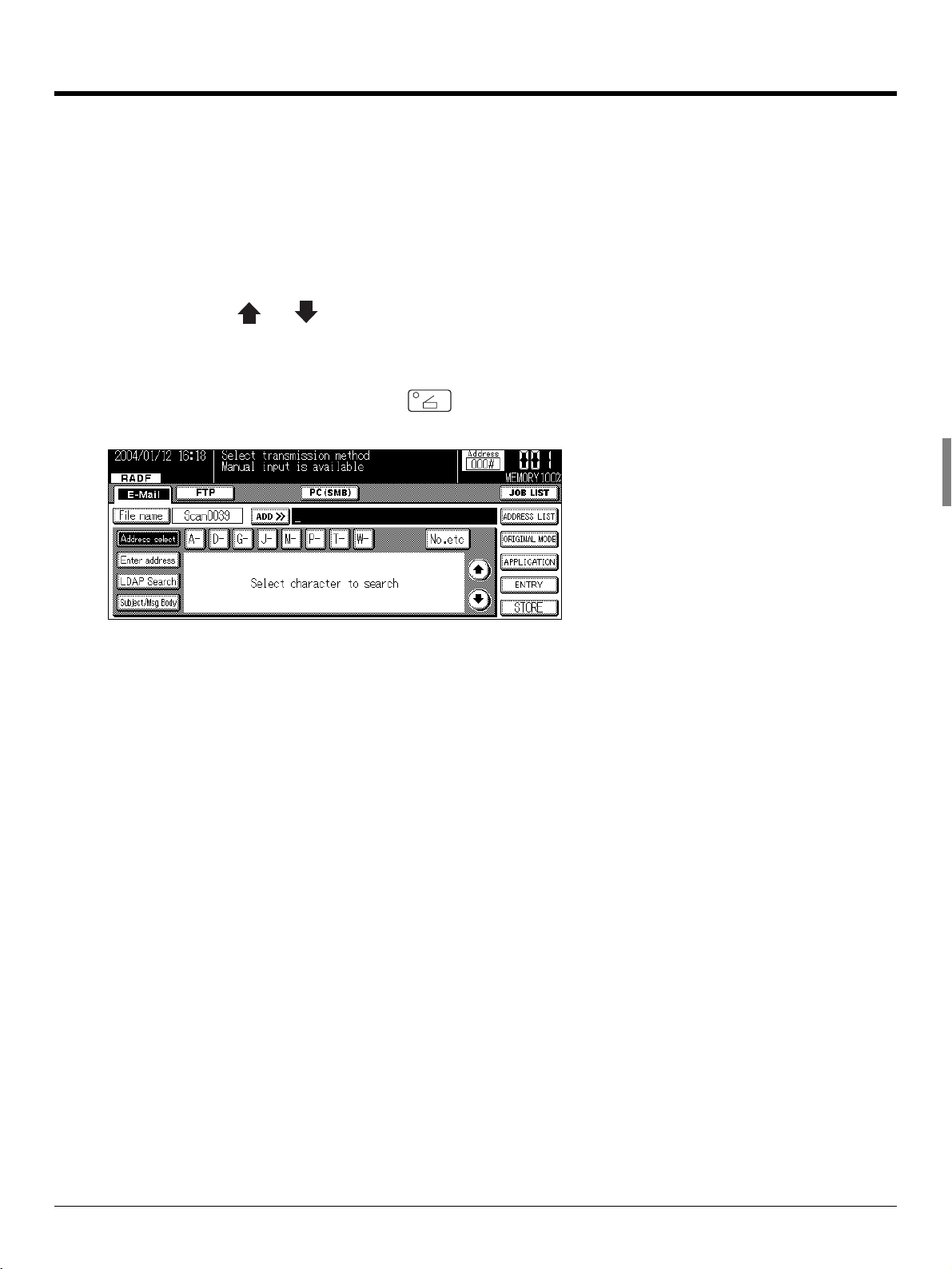
6-1. Selecting the Destination
The printer functions are set by displaying the printer settings screen.
● When the Adobe PostScript driver is selected, the document size cannot be set.
1
Touch the (SCAN/SERVER) button on the control panel.
2
Touch the [E-Mail] key on the LCD screen.
This displays buttons on the control
panel.
This displays the
keys on the LCD
screen.
This covers important information.
This covers items
requiring attention
or warnings and
cautions.
● Always set irregular size paper in the copier's bypass tray.
3
Select [File] - [Import] - [Scan].
4
For [Drives:], select the CD-ROM drive. For folder, double-click the
[\English\Printer\Win9x_Me] folder.
● If there are any files that cannot be deleted, logon again.
The names of windows, dialog boxes,
and icons displayed
on the computer
screen are written in
brackets [ ].
Folder structure is
written from the upper level to lower
level.
vii Using of this Manual
Page 10
Folder Structure on the CD-ROM
●
The folders included on the accompanying CD-ROM are structured as shown below.
This illustration will be helpful for locating specific folders or files.
• In this manual, folder names and file names are not preceded by the root directory.
• You may use the files in the English folder.
User Software CD
Windows
English
Acroread
Scanner
UserGuide
addbook_e_km_vxxx.pdf
webutila_e_km_vxxx.pdf
Japanese
(Adobe Acrobat Reader 5.0)
(TWAIN Scanner Driver)
(Address Book Manual)
Web Utilities Manual)
(
Macintosh
English
Acroread
UserGuide
addbook_e_km_vxxx.pdf
webutila_e_km_vxxx.pdf
(Adobe Acrobat Reader 5.0)
(Address Book Manual)
(
Web Utilities Manual)
Japanese
Folder structure on the CD-ROM viii
Page 11

I Outline
This section summarizes the machine’s network scanning functions and explains control
panel operations.
Chapter 1 Summary of Network Functions ..3
Chapter 2 Before Use ..................................... 9
Chapter 3 Inputting Text ..............................15
1
Page 12

MEMO
2
Page 13

I Outline
Chapter 1 Summary of Network Functions
This chapter summarizes the copier network functions.
1-1. Network/Scanner Function Outline .....................................................4
1-2. Scanner Functions................................................................................5
1-3. Scan Data Output ..................................................................................6
3
Page 14
1-1. Network/Scanner Function Outline
Connection with the Network
Please connect the UTP cable (Category 5 recommended) connected to the network to the Ethernet connector (RJ-45) of the machine.
The settings required for connecting to the network depend on the environment of the network the machine is
connected to, the OS of the computers making up the network, etc. Make the settings required to match the
environment into which this system is being introduced.
Network Setting Method
There are two methods for specifying the machine’s network settings.
Setting from the copier control panel
Load the setting screen from the copier’s control panel and set the network functions.
z For the method setting the network functions from the copier’s control panel, refer to [Chapter 4 Setting from the
Control Panel] ( Page 21).
Setting using the Web Utilities
This sets the network controller from a computer connected to the network using the Web Utilities.
z For details on the Web Utilities, refer to [Chapter 5 Web Utility] ( Page 89).
I Outline Chapter 1 Summary of Network Functions 4
Page 15
1-2. Scanner Functions
Data (scanned data) scanned from the RADF or from the glass bed of the copier from which the original is
scanned can be sent as an E-Mail attached file over the Internet (Scan to E-Mail). The data can be uploaded
to the file server (Scan to FTP) or can be sent directly to a shared folder of PC as a file (Scan to PC (SMB)).
The machine will store the complete file and send out the data in packets.
For details on how to save to the copier's hard disk (Scan to Box), refer to the User’s Guide (Document
Folder).
Scanning documents
Copier
Memory
Network
Sending with E-mail
SMTP server
Send to a
shared folder
PC
FTP server
Uploard to
file server
Before scanning documents, a destination for sending the scanned data needs to be selected from either of
the sending options: (1) [E-Mail], (2) [FTP], or (3) [PC(SMB)].
Also, [Quality], [Magnification Ratio], [Resolution], [Continuous pages], [Erase outside of document] and
other functions can be specified at the same time.
●
Do not send confidential documents from the copier in instances where there is apprehension that the
scanned data could be stolen or illegally accessed.
●
Depending the condition of the network/server, after the scanned data is sent from the copier, the
scanned data may incur damaged. Always make sure to check that the scanned data has not been damaged.
●
When using the scanner functions, connect with the computer via Ethernet. The scanner functions cannot be used from the parallel port.
●
The copier must have the appropriate IP Address assigned and the TCP/IP network is enabled. For
mode details on the network settings, ask the network administrator.
5 I Outline Chapter 1 Summary of Network Functions
Page 16
1-3. Scan Data Output
Scanned data can be selected and sent from three destinations, [Scan to E-Mail], [Scan to FTP] and [Scan to
PC(SMB)].
This section explains these three types of destinations.
Scan to E-Mail
Scanned data can be sent to a specified E-Mail address. Input the address and file name on the copier's LCD
screen and send as an E-Mail attached file.
For more information, refer to [6-1. Selecting the Destination] ( Page 126).
Document
Copier main unit
E-mail and Scanned data
Memory
SMTP server
Transfer to
destination
server
Internet
E-mail
destination
POP server
I Outline Chapter 1 Summary of Network Functions 6
Page 17

1-3. Scan Data Output
Scan to FTP
Scanned data can be uploaded to the specified FTP server. Input the FTP server address, login password,
etc. on the copier's LCD screen.
For more information, refer to [6-1. Selecting the Destination] ( Page 126).
Document
Copier main unit
Scanned data
Memory
Download
FTP server
Internet
7 I Outline Chapter 1 Summary of Network Functions
Page 18
1-3. Scan Data Output
Send to a Shared Folder (Scan to PC (SMB))
Scanned data can be sent to a specified folder in a PC. Input the name and login password of the target PC
from the copier's LCD screen.
For more information, refer to [6-1. Selecting the Destination] ( Page 126).
Document
Copier main unit
Scanned data
Memory
Send to a shared folder
I Outline Chapter 1 Summary of Network Functions 8
Page 19

I Outline
Chapter 2 Before Use
This chapter explains the names of the buttons on the copier's control panel and their functions, the contents of the LCD screen display, and the operations.
2-1. Control Panel Descriptions ................................................................10
2-2. LCD Screen..........................................................................................11
9
Page 20
2-1. Control Panel Descriptions
The buttons on the control panel and the keys displayed on the LCD screen are used to make scanned settings.
This section explains the names and functions of the buttons used for setting operations. For information on
buttons not explained here, refer to the copier User’s Guide.
[CHECK] button
LCD screen [AUTO RESET] button [STOP] button
[CLEAR] button
LCD screen
The LCD screen displays the print controller status, menus used for settings, selection items, and other
such information. To make settings, touch the keys displayed on the screen.
(SCAN/SERVER) button
This switches between scanner/printer mode.
(START) button
This resumes the paused print processing or starts scanning.
(STOP) button
This stops scan processing.
(CLEAR) button
Clear the numeric characters which are entered on the control panel.
(CHECK) button
This displays the settings check screen.
(AUTO RESET) button
This resets settings to their defaults.
Data LED
This flashes green when the copier is receiving data and stays lit when data is accmulated in the copier.
Scanner/Printer LED
This lights up green for scanner/printer mode.
z The LED lights up red when a warning or error message is displayed.
In this case, check the error information on the LCD screen and solve the error. For troubleshooting information, refer
to the copier User’s Guide.
I Outline Chapter 2 Before Use 10
Page 21
2-2. LCD Screen
LCD Screen Operation Methods
Select items by touching the appropriate key displayed on the LCD screen.
Buttons common to all setting screens
When you touch [OK], the results of the operation are applied.
When you touch [CANCEL], the results of the operation are cancelled.
When you touch [ ]or [ ], the screen display is switched.
Basic screen
With the copier started, if you touch the (SCAN/SERVER) button on the control panel, the [Scanner mode basic] screen is displayed on the LCD screen.
11 I Outline Chapter 2 Before Use
Page 22

2-2. LCD Screen
Job List Screen
When you touch the [JOB LIST] key on the [Scanner mode basic] screen, the [JOB LIST] screen is displayed
on the LCD screen and the status of the current print job or fax job can be checked.
Touch the [PRINT JOB] or [FAX JOB] key to switch to the print job or fax job status display.
If there are no scheduled jobs, the column is blank.
When the copier power is turned off, these contents are erased.
Job List Contents
JOB No.
The job number (001 to 999) is displayed.
MODE
This displays the job processing mode (copier/printer/scanner).
STATUS
This displays the status of each job.
Error : An error occurred.
Outputting : The data is being copied/printed/scanned.
No paper : There is no paper in the tray (copy/print mode).
Stopped : Stopped, interrupted, waiting jam processing (each mode).
Scanning : The document is being scanned.
Waiting output : The job has been scheduled and is waiting for copy/print/scan output.
Converting : The data is being converted.
Processing : An E-mail message for "Scan to E-Mail" is being created.
NAME
Displays the JOB Name.
TOTAL PAGE(s)
This displays the number of output pages (1 to 999) set for the job.
PAGE(s) LEFT
This displays the number of pages left to be output (1 to 9999).
Number of pages left to be output = Number of pages (per copy) x Number of copies set
z If the number of pages left to be output is greater than 9999, [*9999] is displayed.
I Outline Chapter 2 Before Use 12
Page 23
2-2. LCD Screen
MINUTE(s) TO GO
This displays the time remaining until job completion in minutes (1 to 999).
z The displayed time is an approximation.The actual time may be somewhat longer or shorter than the time displayed.
z If the time remaining is greater than 999 minutes, [*999] is displayed.
z If the time remaining is less than 1 minute, [<1] is displayed.
Changing Job Order
1
Touch the [ ], [ ] key to select the job to be processed first.
2
Touch the [ADVANCE] key.
→ The selected job is displayed inverted and is moved to next after the job currently being output.
Job Deletion
1
Touch the [ ], [ ] key to select the job to delete.
2
Touch the [DELETE] key.
→ The selected job is deleted from the copier's memory.
Unsuccessful Job List
Touch the [Unsuccessful jobs] key to display a list of jobs that have yet to be completed.
If there are any incomplete scanning jobs or printing jobs they will be displayed here.
This data will be erased once the main power is turned off to the machine.
Unsuccessful Job List Data
MODE
E-mail, FTP, Box, PC(SMB)
File Name
Factor
Cancelled, Auto Delete, etc.
When [Error N**] is displayed in this menu, please refer to Troubleshooting, Chapter 7.
13 I Outline Chapter 2 Before Use
Page 24

MEMOMEMO
14
Page 25

I Outline
Chapter 3 Inputting Text
This chapter explains how to input text for names and descriptions.
3-1. Inputting Text ......................................................................................16
15
Page 26
3-1. Inputting Text
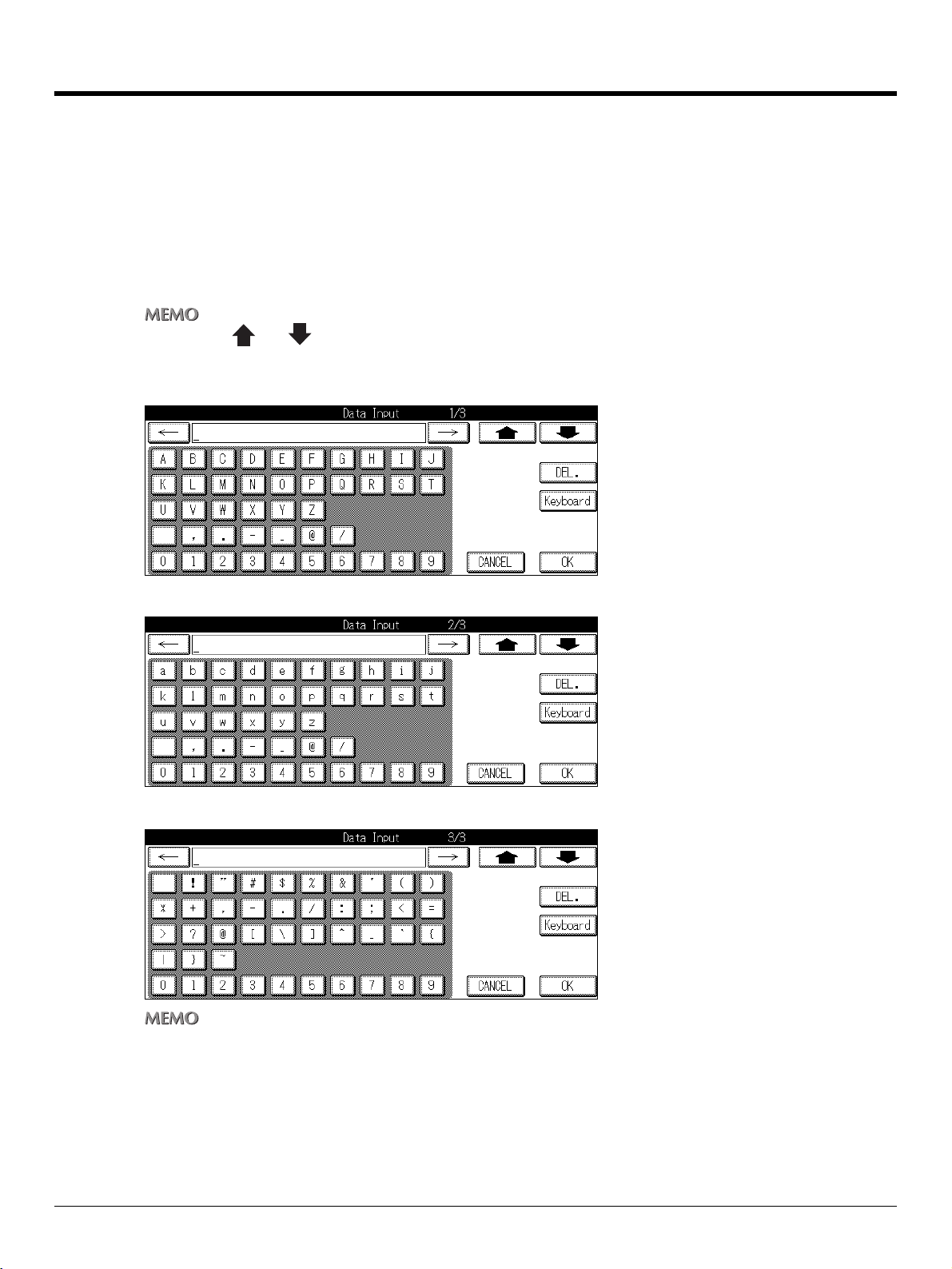
This section explains the operation method for inputting text, used for operations such as registering name
and entering E-mail addresses.
Data Input Screen
Normal Input Screen
There are three kinds of Normal Input screen as below.
z Touch the [ ] or [ ] key to switch to the input character type screen.
z Touch the [Normal] key on the keyboard input screen to switch to QWERTY input mode.
Uppercase letter input screen
Lowercase letter input screen
Number and symbol input screen
z When you touch the [DEL.] key on the LCD screen, the input characters are deleted one at a time.
I Outline Chapter 3 Inputting Text 16
Page 27
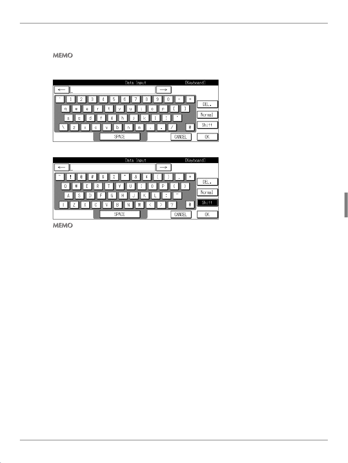
Keyboard Input Screen
There are two kinds of Keyboard screen as below.
z Touch the [Keyboard] key on the normal input screen to switch to QWERTY input mode.
Lowercase letter input screen
Uppercase letter input screen
3-1. Inputting Text
z Touch the [Shift] key also to switch to the input character type screen.
z Touch the [Normal] key while in QWERTY input mode to revert to the previous input mode.
17 I Outline Chapter 3 Inputting Text
Page 28

3-1. Inputting Text
Inputting Text
1
Select a type of the [Data Input] screen.
2
Touch the letter keys on the LCD screen to input the letters.
3
Repeat the step 1 and 2.
4
Touch the [OK] on the LCD screen.
z When you touch the [DEL.] key on the LCD screen, the input characters are deleted one at a time.
I Outline Chapter 3 Inputting Text 18
Page 29

II Network Setup Administrators only
This section explains how to proceed with network settings.
Chapter 4 Setting from the Control Panel .. 21
Chapter 5 Web Utility.................................... 89
19
Page 30

MEMO
20
Page 31

II Network Setup - Administrators only
Chapter 4 Setting from the Control Panel
This chapter explains the method for making the network settings from the Copier’s control
panel.
4-1. Network Setup List..............................................................................22
4-2. Method for Setting Network from Control Panel..............................23
4-3. TCP/IP Setup........................................................................................27
4-4. NetWare Setup..................................................................................... 33
4-5. AppleTalk Setup ..................................................................................41
4-6. IPP Setup .............................................................................................44
4-7. FTP Setup ............................................................................................54
4-8. E-Mail (SMTP) Setup ...........................................................................57
4-9. E-Mail (POP) Setup..............................................................................63
4-10. E-Mail Extended Config ....................................................................69
4-11. Device Setup...................................................................................... 72
4-12. List Print.............................................................................................75
4-13. PC(SMB) Setup..................................................................................76
4-14. LDAP Setup .......................................................................................77
21
Page 32

4-1. Network Setup List
This explains the settings required when connecting the copier to the network.
Set each setting item to match the environment of the network to which the copier is connected. When
changing the setting for each item, ask the network administrator.
TCP/IP Setup ( Page 27
This sets the items required for communicating with TCP/IP.
NetWare Setup ( Page 33)
This sets the items required for communicating with NetWare.
AppleTalk Setup ( Page 41)
This sets the items required for communicating with AppleTalk.
IPP Setup ( Page 44)
This sets the items required for IPP Printing.
FTP Setup ( Page 54)
This sets the items for sending scanned images from the Copier to the FTP server.
E-Mail (SMTP) Setup ( Page 57)
This sets the items required for sending scanned images from the Copier as E-mail attachments.
E-Mail (POP) Setup ( Page 63)
This sets the items required to use the POP server.
E-Mail Extended Config ( Page 69)
This is used to set the Reception/Disposition notifications for E-mail when the Internet fax is used.
Device Setup ( Page 72)
This sets the interface items.
List Print ( Page 75)
This prints out the setup list.
PC(SMB) Setup ( Page 76)
Sets the items required for sending scanned data to a shared folder of PC.
LDAP Setup ( Page 77)
Sets the items required for accessing the LDAP server to acquire a mail address for [Scan to E-Mail].
II Network Setup - Administrators only 22
Chapter 4 Setting from the Control Panel
Page 33

4-2. Method for Setting Network from Control Panel
This explains how to set the network connection using the control panel and LCD screen.
●
After the network settings have been changed, a message "To valid the data, please turn OFF main SW
and ON" may appear on the touch panel. If this message is displayed, be sure to switch the main power
for the copier OFF and wait at least 10 seconds, then turn it back ON.
1 Press the (COPY) button on the control panel.
→ The [Copy basic mode] screen is displayed on the LCD screen.
2 Press the (HELP) button on the control panel, then press the [Key Ope mode] key.
→ The [HELP MODE] screen is displayed on the LCD screen.
23 II Network Setup - Administrators only
Chapter 4 Setting from the Control Panel
Page 34

4-2. Method for Setting Network from Control Panel
3 If a password is set, the key operator's password input screen is displayed. Touch the
[Password] key and input the password in the [Data Input] screen. Then, touch the
[OK] key or input the password (up to 8 digits) using the ten-keys.
4 Touch the [OK] key on the [Password Input] screen.
z The Key operator password is set by your service representative. If the key operator password has been set, the key
operator should keep the password safe on his/her own responsibility.
z For the Key operator password, please ask your service representative.
z If the [Enhanced Security] is used, the password should be 8 digits.
5 Touch the [OK] key.
→ The [Key operator mode] screen is displayed on the LCD screen.
z This screen may not be displayed, depending on which options are set for [4.FAX], [5.Printer] and [6.Document
Folder].
II Network Setup - Administrators only 24
Chapter 4 Setting from the Control Panel
Page 35

4-2. Method for Setting Network from Control Panel
6 Touch the [2.Network] key.
The following settings are made on the [Network setting] screen.
TCP/IP Setup Page 27
NetWare Setup Page 33
AppleTalk Setup Page 41
IPP Setup Page 44
FTP Setup Page 54
E-Mail (SMTP) Setup Page 57
E-Mail (POP) Setup Page 63
E-Mail Extended Config Page 69
Device Setup Page 72
List Print Page 75
PC (SMB) Setup Page 76
LDAP Setup Page 77
z [8. E-Mail Extended Config] is enabled only when the optional hard disk is connected.
7 Select the item to set by touching it.
25 II Network Setup - Administrators only
Chapter 4 Setting from the Control Panel
Page 36

4-2. Method for Setting Network from Control Panel
8 Set each item and when setting of all the items is complete, touch the [OK] key.
→ The display returns to the [Network setting] screen.
z Touching [CANCEL] will return you to the [Network setting] screen without any of the changes taking effect.
IP Address Settings
There are two methods for setting the IP address etc. for the network controller.
Assigning the IP address automatically with the DHCP server
When managing IP addresses with a DHCP server on the network, there is no need to set a unique IP
address for the network controller. The IP address can be assigned automatically from the DHCP
server.
Setting a unique IP address for the network controller
When setting individual IP addresses for equipment connected to the network, the IP address assigned
to the network controller is manually input. In this case, it is also necessary to set the sub-net mask and
other information with manual input.
z For details on management methods for network IP addresses etc., check with your network administrator.
z For details on making network settings manually, check with the network administrator.
z When making network settings manually, in addition to the method explained here using the control panel, you can
also use a web utility. For details, refer to the Web Utilities User’s Guide.
II Network Setup - Administrators only 26
Chapter 4 Setting from the Control Panel
Page 37

4-3. TCP/IP Setup
The information required for using the print controller in the TCP/IP environment is set.
1 Touch the [1.TCP/IP Setup] key on [Network setting] screen.
→ The [TCP/IP Setup] screen is displayed.
z For details on the procedure for displaying the [Network setting] screen, refer to [4-2.Method for Setting Network from
Control Panel] ( Page 23).
Use [TCP/IP] screen to access the following:
[TCP/IP] screen 1/3
Enable TCP/IP Page 28
IP Address Page 28
Subnet Mask Page 28
Default Gateway Page 29
Enable DHCP Page 29
[TCP/IP] screen 2/3
Preferred DNS Server Page 30
Other DNS Server Page 30
RAW Port Number Page 31
[TCP/IP] screen 3/3
DNS Host Name Page 32
DNS Domain Name Page 32
z Use [ ] and [ ] to switch the screen.
2 Touch [OK] key.
→ The display returns to the [Network setting] screen.
z Touching [CANCEL] will return you to the [Network setting] screen without any of the changes taking effect.
27 II Network Setup - Administrators only
Chapter 4 Setting from the Control Panel
Page 38

4-3. TCP/IP Setup
TCP/IP Setup (Part 1 of 3)
1 Access the [TCP/IP Setup] screen (1/3) from the [Network setting] screen.
z For details on the procedure for displaying the [Network setting] screen, refer to [4-2.Method for Setting Network from
Control Panel] ( Page 23).
z Use [ ] and [ ] to switch the screen.
Enable TCP/IP
This sets whether to enable TCP/IP.
1
To disable TCP/IP settings, touch the [OFF] key on the LCD Screen. To enable them touch
the [ON] key.
IP Address
The IP Address is registered on the Network Controller.
1
Touch the [IP Address] key.
2
Use the keys on the control panel to input the IP Address.
Specify four sets of three digit numbers, separated by the periods as the IP Address.
When you touch
z When using a DHCP server for IP Address management, the IP Address acquired with DHCP is displayed.
[] or []
the cursor moves to the left and right.
Subnet Mask
This inputs the subnet mask for the machine’s network.
1
Touch the [Subnet Mask] key.
2
Use the keys on the control panel to input the subnet mask.
Specify four sets of three digit numbers, separated by the periods as the subnet mask.
When you touch
z When using a DHCP server for subnet mask management, the subnet mask acquired with DHCP is displayed.
II Network Setup - Administrators only 28
Chapter 4 Setting from the Control Panel
[] or []
the cursor moves to the left and right.
Page 39

4-3. TCP/IP Setup
Default Gateway
This inputs the gateway for the machine’s network.
1
Touch the [Default Gateway] key.
2
Use the keys on the control panel to input the default gateway address.
Specify four sets of three digit numbers, separated by the periods as the default gateway address.
When you touch
z When using a DHCP server for default gateway address management, the default gateway address acquired with
DHCP is displayed.
[] or []
the cursor moves to the left and right.
Enable DHCP
This sets whether or not to automatically acquire IP Addresses and other such information from a
DHCP (Dynamic Host Configuration Protocol) server.
1
Touch the [ON] or [OFF] key on the [Enable DHCP Setting].
[ON] :When acquiring information from a DHCP server
[OFF] :When not acquiring information from a DHCP Server
z The factory default setting is [ON].
29 II Network Setup - Administrators only
Chapter 4 Setting from the Control Panel
Page 40

4-3. TCP/IP Setup
TCP/IP Setup (Part 2 of 3)
1 Use [ ] or [ ] to access [TCP/IP Setup] screen (2/3) from screen (1/3).
z For details on the procedure for displaying the [Network setting] screen, refer to [4-2.Method for Setting Network from
Control Panel] ( Page 23).
Preferred DNS Server
Sets the address for the preferred DNS Server
1
Touch the [Preferred DNS server] key.
2
Use the keys on the control panel to input the DNS Address.
Specify four sets of three digit numbers, separeted by the periods as the preferred DNS server.
When you touch
[] or []
the cursor moves to the left and right.
Other DNS Server
Sets the address for the other DNS Server
1
Touch the [Other DNS server] key.
Specify four sets of three digit numbers, separated by the periods as the alternate DNS server.
When you touch
2
Use the keys on the control panel to input the DNS Address.
[] or []
the cursor moves to the left and right.
II Network Setup - Administrators only 30
Chapter 4 Setting from the Control Panel
Page 41

RAW Port Number
Allows you to assign a Port Code.
●
Changing the Port Code in an improper manner can result in damage to the network. Do not change the
Port Code unless it is necessary to do so.
1
Touch the [RAW Port Number] key.
2
Using the keys on the control panel, input a Port Code number between 1-65535.
4-3. TCP/IP Setup
31 II Network Setup - Administrators only
Chapter 4 Setting from the Control Panel
Page 42

4-3. TCP/IP Setup
TCP/IP Setup (Part 3 of 3)
1 Use the [ ] or [ ] to access [TCP/IP Setup] screen (3/3) from the screen (2/3).
z For details on the procedure for displaying the [Network setting] screen, refer to [4-2.Method for Setting Network from
Control Panel] ( Page 23).
DNS Host Name
This sets the DNS Host name.
1
Touch the [DNS Host Name] key.
2
Using the data input screen, input the DNS Host name.
DNS Domain Name
This sets the DNS Domain name.
1
Touch the [DNS Domain Name] key.
2
Using the data input screen, input the DNS Domain name.
z For details on character input, refer to [3-1.Inputting Text] ( Page 16).
II Network Setup - Administrators only 32
Chapter 4 Setting from the Control Panel
Page 43

4-4. NetWare Setup
The information required for using the print controller in the NetWare network environment is set.
1 Touch the [2.NetWare Setup] key on [Network setting] screen.
→ The [NetWare Setup] screen is displayed.
z For details on the procedure for displaying the [Network setting] screen, refer to [4-2.Method for Setting Network from
Control Panel] ( Page 23).
Use [NetWare Setup] screen to access the following:
[NetWare Setup] screen 1/3
Enable NetWare Page 35
Ethernet Frame Type Page 35
Print Server Name Page 35
Print Server Password Page 36
[NetWare Setup] screen 2/3
File Server Page 37
NDS Context Page 37
NDS Tree Page 38
[NetWare Setup] screen 3/3
Operating Mode Page 39
Printer Number Page 39
[NetWare Setup : Detail] screen
Print Queue Scan Rate Page 40
Disable Bindery Page 40
z Use [ ] and [ ] to switch the screen.
z For details on NetWare settings, refer to the NetWare User’s Guide.
33 II Network Setup - Administrators only
Chapter 4 Setting from the Control Panel
Page 44

4-4. NetWare Setup
2 Touch [OK] key.
→ The display returns to the [Network setting] screen.
z Touching [CANCEL] will return you to the [Network setting] screen without any of the changes taking effect.
II Network Setup - Administrators only 34
Chapter 4 Setting from the Control Panel
Page 45

4-4. NetWare Setup
NetWare setup (Part 1 of 3)
1 Access to [NetWare Setup] screen (1/3) from [Network setting] screen.
z For details on the procedure for displaying the [Network setting] screen, refer to [4-2.Method for Setting Network from
Control Panel] ( Page 23).
z Use [ ] and [ ] to switch the screen.
Enable NetWare
This sets whether or not to enable the machine’s NetWare capabilities in the network environment.
1
To disable NetWare settings, touch the [OFF] key. To enable them touch the [ON] key.
[ON] :Used in the NetWare environment
[OFF] :Not used in the NetWare environment
Ethernet Frame Type
This sets the frame type used by the machine.
1
Touch the [EDIT] key on the [Ethernet Frame Type] screen.
[EDIT] :Choose from below
[Auto-Sense]→[802.2]→[802.3]→[Ethernet II]→[802.2 SNMP]→[Auto-Sense]
z The factory default setting is [Auto-Sense].
2
Touch [OK] key.
Print Server Name
This sets the Print Server name assigned to the Network Controller.
1
Touch the [Print Server Name] key.
2
Using the [Data Input] screen, input the Print Server name.
3
Touch [OK] key.
→ The screen will return to [NetWare Setup].
35 II Network Setup - Administrators only
Chapter 4 Setting from the Control Panel
Page 46

4-4. NetWare Setup
Print Server Password
This sets the password necessary for the Print Server to login to the File Server.
1
Touch the [Password] key.
2
Using the [Data Input] screen, input the password.
3
Touch [OK] key.
→ The screen will return to [NetWare Setup].
II Network Setup - Administrators only 36
Chapter 4 Setting from the Control Panel
Page 47

4-4. NetWare Setup
NetWare setup (Part 2 of 3)
1 Use [ ] or [ ] to access to [NetWare Setup] screen (2/3) from screen (1/3).
z For details on the procedure for displaying the [Network setting] screen, refer to [4-2.Method for Setting Network from
Control Panel] ( Page 23).
File Server Name
This sets the File Server name that the Print Server will log in with.
1
Touch the [File Server] key.
2
Using the [Data Input] screen, input the file sever name.
3
Touch [OK] key.
→ The screen will return to [NetWare Setup].
NDS Context Name
This sets the NDS (Novell Directory Service) Name.
1
Touch the [NDS Context] key.
2
Using the [Data Input] screen, input the NDS Context name.
3
Touch [OK] key.
→ The screen will return to [NetWare Setup].
37 II Network Setup - Administrators only
Chapter 4 Setting from the Control Panel
Page 48

4-4. NetWare Setup
NDS Tree
This sets the NDS Tree Name.
1
Touch the [NDS Tree] key.
2
Using the [Data Input] screen, input the NDS Tree name.
3
Touch [OK] key.
→ The screen will return to [NetWare Setup].
II Network Setup - Administrators only 38
Chapter 4 Setting from the Control Panel
Page 49

4-4. NetWare Setup
NetWare setup (Part 3 of 3)
1 Use the [ ] or [ ] to access [NetWare Setup] screen (3/3) from screen (2/3).
z For details on the procedure for displaying the [Network setting] screen, refer to [4-2.Method for Setting Network from
Control Panel] ( Page 23).
Operating Mode
This sets up the Operation Mode.
1
Touch the [PServer] or [RPrinter] key.
[PServer] :Select when using the PServer mode.
[RPrinter] :Select when using the RPrinter mode.
Printer Number
This sets the Printer Number.
1
Using the control panel, enter the Printer Number between 0 and 255.
39 II Network Setup - Administrators only
Chapter 4 Setting from the Control Panel
Page 50

4-4. NetWare Setup
Perform the detailed setup for NetWare
1 Touch the [DETAIL] key on the [NetWare Setup] screen.
→ [NetWare Setup :Detail] Screen will be displayed.
z For details on the procedure for displaying the [Network setting] screen, refer to [4-2.Method for Setting Network from
Control Panel] ( Page 23).
Print Queue Scan Rate
This sets the time interval for searching the Print Queue.
1
Using the control panel, enter the time internal between 1 and 65535.
Disable Bindery
This sets whether or not to enable bindery service for NetWare 4.x or later.
1
Touch the [YES] or [NO] keys on the [Disable Bindery] menu.
[YES] :Disables Bindery Service
[NO] :Enables Bindery Service
2 Touch [OK] key.
→ The screen will return to [NetWare Setup].
z Touching [CANCEL] will return you to the [Network setting] screen without any of the changes taking effect.
II Network Setup - Administrators only 40
Chapter 4 Setting from the Control Panel
Page 51

4-5. AppleTalk Setup
Set the information required for using the machine in the AppleTalk network environment.
1 Touch the [3.AppleTalk Setup] key on [Network setting] screen.
→ The [AppleTalk Setup] screen is displayed.
z For details on the procedure for displaying the [Network setting] screen, refer to [4-2.Method for Setting Network from
Control Panel] ( Page 23).
Use [AppleTalk Setup] screen to access the following:
Enable AppleTalk Page 42
Printer Name Page 42
Zone Name Page 43
2 Touch [OK] key.
→ The display returns to the [Network setting] screen.
z Touching [CANCEL] will return you to the [Network setting] screen without any of the changes taking effect.
41 II Network Setup - Administrators only
Chapter 4 Setting from the Control Panel
Page 52

4-5. AppleTalk Setup
AppleTalk setup
1 Access the [AppleTalk Setup] screen from [Network setting] screen.
z For details on the procedure for displaying the [Network setting] screen, refer to [4-2.Method for Setting Network from
Control Panel] ( Page 23).
Enable AppleTalk
This sets whether or not to enable AppleTalk.
1
On the [AppleTalk Setup] screen, touch either the [ON] or [OFF] key.
[ON] :Enables AppleTalk
[OFF] :Disables AppleTalk
z The factory default setting is [ON].
Printer Name
This sets the Machine’s name to be displayed on the AppleTalk network.
1
Touch the [Printer Name] key.
2
Using the data input screen, input the Print Name.
3
Touch [OK] key.
z The Printer Name should not exceed 32 characters.
z For details on character input, refer to [3-1.Inputting Text] ( Page 16).
II Network Setup - Administrators only 42
Chapter 4 Setting from the Control Panel
Page 53

Zone Name
This specifies the zone that the print controller is connected to.
1
Touch the [Zone Name] key.
2
Using the data input screen, input the Print Name.
3
Touch [OK] key.
z The Zone Name should not exceed 32 characters.
z For details on character input, refer to [3-1.Inputting Text] ( Page 16).
z If there is no zone (when using a network with no shielded router), leave this column blank.
4-5. AppleTalk Setup
43 II Network Setup - Administrators only
Chapter 4 Setting from the Control Panel
Page 54

4-6. IPP Setup
This sets the IPP features.
1 Touch the [4.IPP Setup] key on the [Network setting] screen.
→ The [IPP Setup] screen will be displayed.
z For details on the procedure for displaying the [Network setting] screen, refer to [4-2.Method for Setting Network from
Control Panel] ( Page 23).
Use [IPP Setup] screen to access the following:
[IPP Setup] screen 1/4
Enable IPP Page 46
Accept IPP Job Page 46
[IPP Setup] screen 2/4
Message from Operator Page 47
Job Size Page 47
[IPP Setup] screen 3/4
Operation Supported Page 48
[IPP Setup] screen 4/4
Supported Document Format Page 49
[IPP Setup] Printer information screen
Printer Related Information Page 53
z Use [ ] and [ ] to switch the screen.
II Network Setup - Administrators only 44
Chapter 4 Setting from the Control Panel
Page 55

2 Touch [OK] key.
→ The display returns to the [Network setting] screen.
z Touching [CANCEL] will return you to the [Network setting] screen without any of the changes taking effect.
4-6. IPP Setup
45 II Network Setup - Administrators only
Chapter 4 Setting from the Control Panel
Page 56

4-6. IPP Setup
IPP setup (Part 1 of 4)
1 Access to [IPP Setup] screen (1/4) from [Network setting] screen.
z For details on the procedure for displaying the [Network setting] screen, refer to [4-2.Method for Setting Network from
Control Panel] ( Page 23).
z Use [ ] and [ ] to switch the screen.
Enable IPP
This setting activates and deactivates IPP.
1
Touch either the [ON] or [OFF] key on the [Enable IPP] screen.
[ON] :Enables IPP
[OFF] :Disables IPP
Accept IPP Job
1
Touch either the [YES] or [NO] key on the [Accept IPP job] screen.
[YES] :Sets the machine to accept IPP job
[NO] :Sets the machine to decline IPP job
z The factory default setting is [YES].
II Network Setup - Administrators only 46
Chapter 4 Setting from the Control Panel
Page 57

IPP setup (Part 2 of 4)
1 Use [ ] or [ ] to access to [IPP Setup] screen (2/4) from screen (1/4).
z For details on the procedure for displaying the [Network setting] screen, refer to [4-2.Method for Setting Network from
Control Panel] ( Page 23).
Message from Operator
This sets the operator message.
4-6. IPP Setup
1
Touch the [Message from Operator] key.
2
Using the [Data Input] screen, input the message.
3
Touch the [OK] key.
Job Size
This sets the job size.
1
Using the control panel, enter a value between 0 and 4294967.
z The factory default setting is [4294967].
47 II Network Setup - Administrators only
Chapter 4 Setting from the Control Panel
Page 58

4-6. IPP Setup
IPP setup (Part 3 of 4)
1 Use [ ] or [ ] to access to [IPP Setup] screen (3/4) from screen (2/4).
z For details on the procedure for displaying the [Network setting] screen, refer to [4-2.Method for Setting Network from
Control Panel] ( Page 23).
Operation Support Information
This sets operation support information.
1
Activate/Deactivate each task by touching the [ON] or [OFF] key.
Print Job
Validate Job
Cancel Job
Get Job Attributes
Get Jobs
Get Printer Attributes
II Network Setup - Administrators only 48
Chapter 4 Setting from the Control Panel
Page 59

IPP setup (Part 4 of 4)
1 Use [ ] or [ ] to access to [IPP Setup] screen (4/4) from screen (3/4).
z For details on the procedure for displaying the [Network setting] screen, refer to [4-2.Method for Setting Network from
Control Panel] ( Page 23).
Supported Document Format
This sets the types of documents supported.
4-6. IPP Setup
1
[Default] selection menu
Touch the [ON] key under the [Default] category for the document formats to be supported by
default.
z Selecting [ON] in the [Default] selection menu will automatically set the format [ON] in the [Document Format] menu.
2
[Document Format] menu
This selects which document formats are to be supported outside of default settings.
[ON] :Supports the format
[OFF] :Does not support the format
49 II Network Setup - Administrators only
Chapter 4 Setting from the Control Panel
Page 60

4-6. IPP Setup
Printer Related Infomation
1 Touch [Printer Info] on the [IPP Setup] screen.
→ The [Printer Information] screen will be displayed.
z For details on the procedure for displaying the [Network setting] screen, refer to [4-2.Method for Setting Network from
Control Panel] ( Page 23).
Use this screen to access the following:
Printer Name Page 51
Location Page 51
Printer Info Page 51
More Printer Information Page 52
Printer Driver Installer Page 52
Printer Model Page 52
Printer Manufacture Page 53
z Use [ ] and [ ] to switch the screen.
2 Touch [OK] key.
→ The screen will return to [IPP Setup] screen.
z Touching [CANCEL] will return you to the [IPP Setup] screen without any of the changes taking effect.
II Network Setup - Administrators only 50
Chapter 4 Setting from the Control Panel
Page 61

Printer Information (Part 1 of 3)
1 Access to [Printer Information] screen (1/3) from [IPP Setup] screen.
z For details on the procedure for displaying the [Network setting] screen, refer to [4-2.Method for Setting Network from
Control Panel] ( Page 23).
z Use [ ] and [ ] to switch the screen.
Printer Name
4-6. IPP Setup
1
Touch the [Printer Name] key.
2
Use the [Data Input] screen to enter the printer name.
3
Touch the [OK] key.
Location
1
Touch the [Location] key.
2
Use the [Data Input] screen to enter the printer location.
3
Touch the [OK] key.
Printer Information
1
Touch the [Printer Info] key.
2
Use the [Data Input] screen to enter the printer information.
3
Touch the [OK] key.
51 II Network Setup - Administrators only
Chapter 4 Setting from the Control Panel
Page 62

4-6. IPP Setup
Printer Information (Part 2 of 3)
1 Use [ ] or [ ] to access to [Printer Information] screen (2/3) from screen (1/3).
z For details on the procedure for displaying the [Network setting] screen, refer to [4-2.Method for Setting Network from
Control Panel] ( Page 23).
More Printer Information
1
Touch the [More Printer Information] key.
2
Use the [Data Input] screen to enter the printer details.
3
Touch the [OK] key.
Printer Driver Installer
1
Touch the [Printer Driver Installer] key.
2
Use the [Data Input] screen to enter the location of the printer driver.
3
Touch the [OK] key.
Printer Model
1
Touch the [Printer Model] key.
2
Use [Data Input] screen to enter the printer model information.
3
Touch the [OK] key.
II Network Setup - Administrators only 52
Chapter 4 Setting from the Control Panel
Page 63

4-6. IPP Setup
Printer Information (Part 3 of 3)
1 Use [ ] or [ ] to access to [Printer Information] screen (3/3) from screen (2/3).
z For details on the procedure for displaying the [Network setting] screen, refer to [4-2.Method for Setting Network from
Control Panel] ( Page 23).
Printer Manufacturer
1
Touch the [Printer Manufacture] key.
2
Use the [Data Input] screen to enter the printer manufacturer information.
3
Touch the [OK] key.
53 II Network Setup - Administrators only
Chapter 4 Setting from the Control Panel
Page 64

4-7. FTP Setup
Makes settings required for uploaded scanned data to an FTP server.
1 Touch the [5.FTP Setup] key on [Network setting] screen on the LCD screen.
→ The [FTP Setup] screen is displayed.
z For details on the procedure for displaying the [Network setting] screen, refer to [4-2.Method for Setting Network from
Control Panel] ( Page 23).
z For details on the scanner function, refer to [Chapter 5 Web Utility] ( Page 89).
The following settings are made on this screen.
[FTP Setup] screen 1/2
Proxy Server Page 55
Proxy Port Number Page 55
Enable PASV Mode Page 55
[FTP Setup] screen 2/2
FTP Client Port No. Page 56
Connection Timeout Page 56
z Use [ ] and [ ] to switch the screen.
2 Touch [OK] key.
→ The display returns to the [Network setting] screen.
z Touching [CANCEL] will return you to the [Network setting] screen without any of the changes taking effect.
II Network Setup - Administrators only 54
Chapter 4 Setting from the Control Panel
Page 65

FTP Setup (Part 1 of 2)
1 Access to [FTP Setup] screen (1/2) from [Network setting] screen.
z For details on the procedure for displaying the [Network setting] screen, refer to [4-2.Method for Setting Network from
Control Panel] ( Page 23).
z Use [ ] and [ ] to switch the screen.
Proxy Server
This sets the Proxy Server for use with communications with the FTP Server.
4-7. FTP Setup
1
Touch the [Proxy Server] key.
2
Using [Data Input] screen, enter the Proxy Server number.
z Set the proxy server number when communications need to be performed using the proxy server.
The format for the supported proxy server is "USER user@hostname."
Proxy Port Number
This specifies a Proxy Port number.
1
Using the control panel, enter the Proxy Server Port number between 1 and 65535.
Enable PASV Mode
This sets whether to enable or disable PASV Mode.
1
Touch either the [YES] or [NO] key on the [Enable PASV Mode] menu.
[YES] :To enable PASV mode
[NO] :To disable PASV mode
55 II Network Setup - Administrators only
Chapter 4 Setting from the Control Panel
Page 66

4-7. FTP Setup
FTP Setup (Part 2 of 2)
1 Use [ ] or [ ] to access to [FTP Setup] screen (2/2) from screen (1/2).
z For details on the procedure for displaying the [Network setting] screen, refer to [4-2.Method for Setting Network from
Control Panel] ( Page 23).
FTP Client Port Number
This specifies a port number to use for communicating with the FTP server.
●
Changing the Port Code in an improper manner can result in damage to the network. Do not change the
Port Code unless it is necessary to do so.
1
Touch the [FTP Client Port No.] key.
2
Using the control panel, enter a number between 1 and 65535.
z The factory default setting is [21].
Connection Timeout
This function automatically stops the upload if communications bog down during data uploading to the
FTP server and a certain period of time elapses.
[Conncetion Timeout] sets this time value.
1
Touch the [Connection Timeout] key.
2
Using the control panel, enter the number of seconds for timeout between 5 and 300.
z The factory default setting is [60] seconds.
II Network Setup - Administrators only 56
Chapter 4 Setting from the Control Panel
Page 67

4-8. E-Mail (SMTP) Setup
This sets the information for the SMTP (Simple Mail Transfer Protocol) necessary for sending images as Email attachments with the scanner functions. The POP before SMTP feature (which confirms SMTP before
sending) can also be set from this menu.
1 Touch the [6.E-Mail (SMTP) Setup] key on [Network setting] screen.
→ The [E-Mail (SMTP) Setup] screen is displayed.
z For details on the procedure for displaying the [Network setting] screen, refer to [4-2.Method for Setting Network from
Control Panel] ( Page 23).
Use this screen to access the following:
[E-Mail (SMTP) Setup] screen 1/2
Enable SMTP Page 58
SMTP Server Page 58
Binary Division Page 59
[E-Mail (SMTP) Setup] screen 2/2
Conection Timeout Page 60
Maximum Msg Size Page 60
[E-Mail (SMTP) Setup : Detail] screen
SMTP Port Number Page 61
POP before SMTP Page 62
z Use [ ] and [ ] to switch screens.
2 Touch [OK] key.
→ The display returns to the [Network setting] screen.
z Touching [CANCEL] will return you to the [Network setting] screen without any of the changes taking effect.
57 II Network Setup - Administrators only
Chapter 4 Setting from the Control Panel
Page 68

4-8. E-Mail (SMTP) Setup
E-Mail (SMTP) Setup (Part 1 of 2)
1 Access to [E-Mail (SMTP) Setup] screen (1/2) from [Network Setting] screen.
z For details on the procedure for displaying the [Network setting] screen, refer to [4-2.Method for Setting Network from
Control Panel] ( Page 23).
z Use [ ] and [ ] to switch screens.
Enable SMTP
This sets whether or not to enable the machine’s E-Mail capabilities.
1
Touch either the [ON] or [OFF] key on the [Enable SMTP] menu.
[ON] :Enables the E-Mail capability
[OFF] :Disables the E-Mail capability
SMTP Server
This sets the name of the SMTP server used for sending E-mail.
1
Touch the [SMTP Server] key.
2
Using the [Data Input] screen, input the name or IP address of the SMTP server used for
sending E-mail.
●
Unless the DNS settings are made correctly, the system will not operate correctly even if the SMTP
server name is entered.
z The SMTP server name is a combination of up to 239 symbols and alphanumerics.
z For details on character input refer to [3-1.Inputting Text] ( Page 16).
II Network Setup - Administrators only 58
Chapter 4 Setting from the Control Panel
Page 69

4-8. E-Mail (SMTP) Setup
Binary Division
This sets the partial message size for sending messages with binary division.
1
Touch either the [YES] or [NO] button on the Binary Division Menu.
[YES] :To enable binary division.
[NO] :To disable binary division.
2
When selecting [YES] on this menu, enter a binary division size between 100 and 10000
kbytes by using the control panel.
z Divided mail messages are combined using the mail software on the receiving side.
59 II Network Setup - Administrators only
Chapter 4 Setting from the Control Panel
Page 70

4-8. E-Mail (SMTP) Setup
E-Mail (SMTP) Setup (Part 2 of 2)
1 Use [ ] or [ ] to access to [E-Mail (SMTP) Setup] screen (2/2) from screen (1/2).
z For details on the procedure for displaying the [Network setting] screen, refer to [4-2.Method for Setting Network from
Control Panel] ( Page 23).
Connection Timeout
This function automatically stops the sending if communications bog down during data uploading to the
SMTP server and a certain period of time elapses.
[SMTP Timeout] sets this time value.
1
Touch the [EDIT] key on the [Connection Timeout] menu.
Each touch of the key will extend the timeout setting by 30 seconds, with a maximum value of 300
seconds.
Maximum Message Size
This sets the maximum capacity that the SMTP server can receive for one E-mail.
1
Touch the [000] digit key on the [Maximum Msg Size] menu.
Using the control panel, enter value between 0 and 100MB.
z The factory set default setting is [0] (unlimited).
z A message which exceeds the maximum message-size setting cannot be sent. Mail messages that have not been
sent are placed on the unsent mail list.
II Network Setup - Administrators only 60
Chapter 4 Setting from the Control Panel
Page 71

E-Mail (SMTP) Detail Setup
1 Touch the [DETAIL] key on [E-Mail (SMTP) Setup] screen.
→ [E-Mail (SMTP) Setup : Detail] screen is displayed.
4-8. E-Mail (SMTP) Setup
SMTP Port Number
This specifies a port number to use for communications with the SMTP server.
●
Changing the Port Code in an improper manner can result in damage to the network. Do not change the
Port Code unless it is necessary to do so.
1
Touch the [SMTP Port Number] key.
2
Using the control panel, enter a number between 1 and 65535.
61 II Network Setup - Administrators only
Chapter 4 Setting from the Control Panel
Page 72

4-8. E-Mail (SMTP) Setup
POP before SMTP
This setting enables or disables SMTP confirmation before transmitting.
1
Touch either the [YES] or [NO] key in the [POP before SMTP] menu.
[YES] :Enables SMTP confirmation
[NO] :Disables SMTP confirmation
2
When [YES] is selected, touch the [Setup Time] key.
3
Using the control panel, enter a time value in seconds between 0 and 60.
2 Touch [OK] key.
→ The Screen will return to [E-Mail (SMTP) Setup] screen.
z Touching [CANCEL] will return you to the [E-Mail (SMTP) Setup] screen without any of the changes taking effect.
II Network Setup - Administrators only 62
Chapter 4 Setting from the Control Panel
Page 73

4-9. E-Mail (POP) Setup
This sets the POP (Post Office Protocol) information necessary for receiving E-mail.
1 Touch the [7.E-Mail (POP) Setup] key on the [Network setting] screen.
→ [E-Mail (POP) Setup] screen will be displayed.
z For details on the procedure for displaying the [Network Setting] screen, refer to [4-2.Method for Setting Network
from Control Panel] ( Page 23).
Use this screen to access the following:
[E-Mail (POP) Setup] screen 1/2
Enable POP Page 64
POP Server Page 64
Login Name Page 64
Password Page 65
[E-Mail (POP) Setup] screen 2/2
Polling Interval Page 66
Interval Time Page 66
[E-Mail (POP) Setup : Detail] screen
POP Port Number Page 67
Connection Time Out Page 68
z Use [ ] and [ ] to switch the screen.
2 Touch [OK] key.
→ The display returns to the [Network setting] screen.
z Touching [CANCEL] will return you to the [Network setting] screen without any of the changes taking effect.
63 II Network Setup - Administrators only
Chapter 4 Setting from the Control Panel
Page 74

4-9. E-Mail (POP) Setup
E-Mail (POP) Setup (Part 1 of 2)
1 Access to [E-Mail (POP) Setup] screen from [Network setting] screen.
z For details on the procedure for displaying the [Network setting] screen, refer to [4-2.Method for Setting Network from
Control Panel] ( Page 23).
z Use [ ] and [ ] to switch the screen.
Enable POP
This setting enables the E-Mail reception.
1
Touch either the [ON] or [OFF] key on the [Enable POP] screen.
[ON] : Enables the E-mail capability
[OFF] : Disables the E-mail capability
z The [ON] and [OFF] keys might not be displayed in some version.
POP Server
This sets the name of the POP server used for receiving E-mail.
1
Touch the [POP Server] key.
2
Using the [Data Input] screen, input the name or IP address of the POP server used for
receiving E-mail.
3
Touch [OK] key.
z The SMTP server name is a combination of up to 239 symbols and alphanumerics.
z For details on character input refer to [3-1.Inputting Text] ( Page 16).
Login Name
This sets the login name used for connecting to the POP server.
1
Touch the [Login Name] key.
2
Using the [Data Input] screen, input the desired login name.
3
Touch [OK] key.
II Network Setup - Administrators only 64
Chapter 4 Setting from the Control Panel
Page 75

Password
This sets the password used for connecting to the POP server.
1
Touch the [Password] key.
2
Using the [Data Input] screen, input the password.
3
Touch [OK] key.
4-9. E-Mail (POP) Setup
65 II Network Setup - Administrators only
Chapter 4 Setting from the Control Panel
Page 76

4-9. E-Mail (POP) Setup
E-Mail (POP) Setup (Part 2 of 2)
1 Use [ ] or [ ] to access to [E-Mail (POP) Setup] screen (2/2) from screen (1/2).
z For details on the procedure for displaying the [Network setting] screen, refer to [4-2.Method for Setting Network from
Control Panel] ( Page 23).
Polling Interval
This function automatically checks for new messages on the POP server at regular intervals.
1
Touch either the [YES] or [NO] key in the [Polling Interval] menu.
[YES] :Enables automatic polling
[NO] :Disables automatic polling
2
When choosing [YES], use the control panel to enter a number, in minutes, between 1 and 60.
z The factory default setting is [15] minutes.
II Network Setup - Administrators only 66
Chapter 4 Setting from the Control Panel
Page 77

E-Mail (POP) Detail Setup
1 Touch the [DETAIL] key on [E-Mail (POP) Setup] screen.
→ [E-Mail (POP) Setup : Detail] screen is displayed
4-9. E-Mail (POP) Setup
POP Port Number
This specifies a port number to use for communications with the POP server.
●
Changing the Port Code in an improper manner can result in damage to the network. Do not change the
Port Code unless it is necessary to do so.
1
Using the control panel, enter a number between 1 and 65535.
67 II Network Setup - Administrators only
Chapter 4 Setting from the Control Panel
Page 78

4-9. E-Mail (POP) Setup
POP Connection Timeout
This function automatically stops the upload if communications bog down during data reception to the
POP server and a certain period of time elapses.
[POP Timeout] sets this time value.
1
Touch the [EDIT] key on the [Connection Timeout] menu.
Each touch of the key will extend the timeout setting by 30 seconds, with a maximum value of 300
seconds.
2 Touch [OK] key.
→ The screen will return to [E-Mail (POP) Setup] screen.
z Touching [CANCEL] will return you to the [E-Mail (POP) Setup] screen without any of the changes taking effect.
II Network Setup - Administrators only 68
Chapter 4 Setting from the Control Panel
Page 79

4-10. E-Mail Extended Config
This sets functions related to reception and disposition notifications for E-mail when the Internet fax is in use.
●
E-Mail Extended Config is enabled only when the optional hard disk is installed. E-Mail Extended Config
cannot be used when the optional hard disk is not installed.
1 Touch the [8. E-Mail Extended Config] key on the [Network Setting] screen.
→ [E-Mail Extended Config] screen will be displayed.
z For details on the procedure for displaying the [Network setting] screen, refer to [4-2.Method for Setting Network from
Control Panel] ( Page 23).
Use this screen to access the following:
DSN Request Page 70
MDN Request Page 71
Response Timeout for MDN/DSN Page 71
MDN Response Page 71
2 When setting of all the required items has been completed, touch the [OK] key on the
control panel.
→ The display returns to the [Network setting] screen.
z Touching [CANCEL] will return you to the [Network setting] screen without any of the changes taking effect.
69 II Network Setup - Administrators only
Chapter 4 Setting from the Control Panel
Page 80

4-10. E-Mail Extended Config
This sets the extended E-mail functions.
1 Access to [E-Mail Extended Config] screen from [Network Setting] screen.
z For details on the procedure for displaying the [Network setting] screen, refer to [4-2.Method for Setting Network from
Control Panel] ( Page 23).
DSN Request
This sets whether or not to request the receiving mail server for sending DSN (Delivery Status Notifications) to the sender when an E-mail message is delivered to the receiving mail server.
1
Touch the [YES] or [NO] keys on the [DSN Request] menu.
[YES] : Requests DSN.
[NO] : Does not request DSN.
z The factory default setting is [NO].
●
Even if DSN is requested, the DSN response mail cannot be received by the sender if the receiving mail
server does not support the DSN function or the server has disabled the response function.
II Network Setup - Administrators only 70
Chapter 4 Setting from the Control Panel
Page 81

4-10. E-Mail Extended Config
MDN Request
This enables setting whether or not to request the receiver for sending MDN (Message Disposition Notifications) to the sender when the receiver opens the received E-mail message.
1
Touch the [YES] or [NO] keys on the [MDN Request] menu.
[YES] : Requests MDN.
[NO] : Does not request MDM
z The factory default setting is [YES].
●
Even if a MDN is requested, the MDN response mail cannot be received by the sender if receiver does
not support the MDN function or receiver has disabled the response function.
Response Timeout for MDN/DSN
This enables setting time for waiting for a response when a transmission result is requested.
1
Input the time between 0 to 99 hours using the ten-key on the control panel.
●
In cases when no response is received after the Response Timeout for MDN/DSN has elapsed, nothing
is registered in the communication status report even when a response is received later.
z The factory default setting is [24] hours.
z For the output method for the communication status report, refer to the "User's Guide (Internet Fax/Facsimile)".
MDN Response
This enables setting whether or not to send a reception result response E-mail when a MDN transmission is requested by the sender.
1
Touch the [YES] or [NO] keys on the [MDN Response] menu.
[YES] : Sends E-mail for reception result response.
[NO] : Does not send E-mail for reception result response.
z The factory default setting is [Yes].
71 II Network Setup - Administrators only
Chapter 4 Setting from the Control Panel
Page 82

4-11. Device Setup
This sets device information.
1 Touch the [9.Device Setup] key on the [Network setting] screen.
→ [Device Setup] screen is displayed.
z For details on the procedure for displaying the [Network setting] screen, refer to [4-2.Method for Setting Network from
Control Panel] ( Page 23).
Use this screen to access the following:
[Device Setup] screen 1/2
MAC Address Page 73
Network Speed Page 73
[Device Setup] screen 2/2
Parallel Receiving (IEEE1284) Page 74
USB Page 74
Network Receiving Page 74
z Use [ ] and [ ] to switch the screen.
2 Touch [OK] key.
→ The display returns to the [Network setting] screen.
z Touching [CANCEL] will return you to the [Network setting] screen without any of the changes taking effect.
II Network Setup - Administrators only 72
Chapter 4 Setting from the Control Panel
Page 83

Device Setup (Part 1 of 2)
1 Access to [Device Setup] screen from [Network setting] screen.
z For details on the procedure for displaying the [Network setting] screen, refer to [4-2.Method for Setting Network from
Control Panel] ( Page 23).
z Use [ ] and [ ] to switch the screen.
MAC Address
This confirm the MAC Address.
4-11. Device Setup
Network Speed
This sets the network speed.
1
Touch the [EDIT] key on the [Network Speed] menu.
[EDIT] : Choose from below
[Auto]→[10Mbps FullDuplex]→[100Mbps FullDuplex]→[100Mbps HalfDuplex]
z The factory set default setting is [AUTO].
73 II Network Setup - Administrators only
Chapter 4 Setting from the Control Panel
Page 84

4-11. Device Setup
Device Setup (Part 2 of 2)
This sets the timeout for the local interface.
1 Use [ ] or [ ] to access [Device Setup] screen (2/2) from screen (1/2).
z For details on the procedure for displaying the [Network setting] screen, refer to [4-2.Method for Setting Network from
Control Panel] ( Page 23).
Parallel Receiving (IEEE 1284)
1
Touch the [IEEE 1284] key.
2
Using the control panel, enter a value in seconds between 10 and 300.
USB
1
Touch the [USB] key.
2
Using the control panel, enter a value, in seconds, between 10 and 300.
Network Receiving
1
Touch the [Network (Rx)] key.
2
Using the control panel, enter a value in seconds between 10 and 300.
II Network Setup - Administrators only 74
Chapter 4 Setting from the Control Panel
Page 85

4-12. List Print
This prints out the Network setting list.
1
Touch the [10.List print] key on the [Network setting] screen.
→ The [List print] screen will be displayed.
z For details on the procedure for displaying the [Network setting] screen, refer to [4-2.Method for Setting Network from
Control Panel] ( Page 23).
2 Touch the [PRINT] key to print out Network setup list.
3 Touch [RETURN] key.
→ The screen will return to the [Network setting] screen.
75 II Network Setup - Administrators only
Chapter 4 Setting from the Control Panel
Page 86

4-13. PC(SMB) Setup
This enables a function for sending data to a PC's shared folder using the scanner function.
1 Touch the [11.PC(SMB) Setup] key on the [Network Setting] screen.
The [PC(SMB) Setup] screen will be displayed.
→
z For details on the procedure for displaying the [Network setting] screen, refer to [4-2.Method for Setting Network from
Control Panel] ( Page 23).
2 Touch either the [ON] or [OFF] key on the [PC(SMB) Setup] screen.
[ON] : Enables the [Scan to PC(SMB)] function
[OFF] : Disables the [Scan to PC(SMB)] function
3 Touch [OK] key.
→
The display returns to the [Network setting] screen.
z Touching [CANCEL] will return you to the [Network setting] screen without any of the changes taking effect.
II Network Setup - Administrators only 76
Chapter 4 Setting from the Control Panel
Page 87

4-14. LDAP Setup
This sets the information required for accessing the LDAP server to acquire E-mail addresses for [Scan to EMail].
●
If the LDAP Setup is not set up correctly, it could cause network problems. This setup process must be
performed only by the server's administrator.
1 Touch the [12.LDAP Setup] key on the [Network Setting] screen.
The [LDAP Setup] screen will be displayed.
→
z For details on the procedure for displaying the [Network Setting] screen, refer to [4-2.Method for Setting Network
from Control Panel] ( Page 23).
z For details on the setup procedure of LDAP, refer to the instruction manual of the LDAP server to be used.
Use [LDAP Setup] screen to access the following:
[LDAP Server Setup] screen 1/4
Enable LDAP Page 79
Maximum Hit Number Page 79
Search Timeout Page 79
Connect Chk Page 80
[LDAP Server Setup] screen 2/4
Server address Page 81
Search Root Page 81
77 II Network Setup - Administrators only
Chapter 4 Setting from the Control Panel
Page 88

4-14. LDAP Setup
[LDAP Server Setup] screen 3/4
Enable SSL Page 82
Port No. Page 82
Authentication Type Page 83
User authentication Page 83
[LDAP Server Setup] screen 4/4
User Name Page 84
Password Page 84
Domain name Page 85
[Detail search initial setting] screen
Attribute Page 86
Condition Page 87
z Use [ ] and [ ] to switch the screen.
2 When setting of all the items has been completed, touch the [RETURN] key.
→ The display returns to the [Network setting] screen.
II Network Setup - Administrators only 78
Chapter 4 Setting from the Control Panel
Page 89

4-14. LDAP Setup
LDAP Server Setup (Part 1 of 4)
1 Access to [LDAP Server Setup] screen (1/4) from [Network Setting] screen.
z For details on the procedure for displaying the [Network setting] screen, refer to [4-2.Method for Setting Network from
Control Panel] ( Page 23).
z Use [ ] and [ ] to switch the screen.
Enable LDAP
This sets whether or not to use the mail address search function for [Scan to E-Mail] by LDAP.
1
Touch either the [ON] or [OFF] key on the [Enable LDAP] menu.
[ON] : Enables the mail address search function with the LDAP.
[OFF] : Disables the mail address search function with the LDAP.
Maximum Hit Number
Sets the maximum number of items to be displayed after search. When the number of searched items
exceeds the maximum number of search items, the items in excess of the maximum search number will
not be displayed.
1
Touch the [Maximum Hit Number] key.
2
Using the control panel, enter a number between 5 and 100.
Search Timeout
Sets the maximum standby time during search processing. If this time is exceeded, the search will be
interrupted.
1
Touch the [Search Timeout] key.
2
Using the control panel, enter a number between 5 and 300.
79 II Network Setup - Administrators only
Chapter 4 Setting from the Control Panel
Page 90

4-14. LDAP Setup
Connect Chk
Connects to the LDAP server to check that the settings for LDAP Setup are correct.
1
Touch the [Connect Chk] key.
2
Check the message on the touch panel.
z Connect Chk can be executed on all [LDAP Server Setup] screens (1/4~4/4).
z If an error message is displayed on the touch panel, refer to [7-2. Network Error List] ( page 183).
II Network Setup - Administrators only 80
Chapter 4 Setting from the Control Panel
Page 91

LDAP Server Setup (Part 2 of 4)
4-14. LDAP Setup
1 Use
or
[]
z For details on the procedure for displaying the [Network setting] screen, refer to [4-2.Method for Setting Network from
Control Panel] ( Page 23).
to access to [LDAP Server Setup] screen (2/4) from screen (1/4).
[]
Server address
Sets the address of the LDAP server.
1
Touch the [Server address] key.
2
Using [Data Input] screen, enter the LDAP server name or IP address.
3
Touch the [OK] key on the [Data Input] screen.
Search Root
Inputs the directory path for the LDAP server to be searched.
1
Touch the [Search Root] key.
2
Input the search route on the [Data Input] screen.
●
If the Search Root is not specified correctly, the search function will not function normally.
Input example 1 : When searching the [Users] container on the [cso.konicaminolta.jp] server:
cn=Users, dc=cso, dc=konicaminolta, dc=jp,
Input example 2 : When searching the OU which is titled [Mail] on the [cso.konicaminolta.jp]server:
ou=Mail, dc=cso, dc=konicaminolta, dc=jp,
3
Touch the [OK] key on the [Data Input] screen.
81 II Network Setup - Administrators only
Chapter 4 Setting from the Control Panel
Page 92

4-14. LDAP Setup
LDAP Server Setup (Part 3 of 4)
1 Use [ ] and [ ] to access to [LDAP Server Setup] screen (3/4) from screen (2/4).
z For details on the procedure for displaying the [Network setting] screen, refer to [4-2.Method for Setting Network from
Control Panel] ( Page 23).
Enable SSL
Sets whether or not to use SSL (Secure Socket Layer) when connecting to the LDAP server.
1
Touch either the [ON] or [OFF] key in the [Enable SSL] menu.
[ON] : Enables SSL
[OFF] : Disables SSL
Port No.
Sets the port number for the LDAP server.
●
If the Port No. is changed improperly, it could cause network problems. Do not change the port number
unless it is necessary for a particular reason.
1
Using the control panel, enter a number between 1 and 65535.
z The port number is changed automatically according to the settings for the [Enable SSL].
When [ON] is selected : 636
When [OFF] is selected : 389
II Network Setup - Administrators only 82
Chapter 4 Setting from the Control Panel
Page 93

4-14. LDAP Setup
Authentication Type
Sets the authentication type when logging on the LDAP server.
1
Touch the [EDIT] key on the [Authentication Type] menu.
Each time touching the [EDIT] key, the selected item toggles in the following order:
anonymous→simple→DIGEST_MD5/CRAM_MD5→GSS-SPNEGO
anonymous : An authentication type which does not require a user name and password
simple : A simplified authentication type which requires a user name and password
DIGEST_MD5/CRAM_MD5: An authentication type which can be used by the general LDAP server
GSS-SPNEGO : An authentication type which can be used by the active directory of Windows
(Kerberos authentication)
●
If the items on the following page are not set correctly by Authentication Type, [Connect Chk] cannot be
performed.
· [Simple] and [DIGEST_MD5/CRAM_MD5] : [User Name]
· [GSS-SPNEGO] : [User Name], [Domain Name]
z The factory default setting is [anonymous].
z Set Authentication Type according to the Authentication Type used for the LDAP server. For details, refer to the
instruction manual of the LDAP server to be used.
User authentication
Allows the server to be accessed freely by the user set according to the instructions on the following
page or by performing user authentication each time the server is accessed.
1
Touch either the [ON] or [OFF] key in the [User authentication] menu.
[ON] : Performs user authentication each time the server is accessed
[OFF] : Permits access to the server by the user set as instructed on the following pages
●
If the items on the following page are not set correctly by the combination of Authentication Type and
User authentication, you cannot touch [OK].
· When [Simple] and [DIGEST_MD5/CRAM_MD5] are selected and user authentication is [OFF] :
[User Name]
· When [GSS-SPNEGO] is selected and user authentication is [OFF] : [User Name], [Domain Name]
· When [GSS-SPNEGO] is selected and user authentication is [ON] : [Domain Name]
z When [anonymous] is selected for [Authentication Type], [OFF] will be automatically selected.
83 II Network Setup - Administrators only
Chapter 4 Setting from the Control Panel
Page 94

4-14. LDAP Setup
LDAP Server Setup (Part 4of 4)
1 Use [ ] and [ ] to access to [LDAP Server Setup] screen (4/4) from screen (3/4).
●
When [OFF] is selected for [User authentication] on the previous page, be sure to set this item.
●
When [ON] is selected for [User authentication] on the previous page, the settings for this item are not
saved. If the settings for this item have already been made, selecting [ON] deletes the user name and
password.
z For details on the procedure for displaying the [Network setting] screen, refer to [4-2.Method for Setting Network from
Control Panel] ( Page 23).
User Name
Sets the User Name to access the LDAP server.
z Only half-width alphanumeric characters can be used for User Name.
1
Touch the [User Name] key.
2
Enter the user name on the [Data Input] screen.
3
Touch the [OK] key on the [Data Input] screen.
Password
Sets the Password for accessing the LDAP server.
1
Touch the [Password] key.
2
Enter the password on the [Data Input] screen.
3
Touch the [OK] key on the [Data Input] screen.
II Network Setup - Administrators only 84
Chapter 4 Setting from the Control Panel
Page 95

Domain name
Set the Domain name for accessing the LDAP server as required.
z Usually entering the Domain name is not required.
z When [GSS-SPNEGO] is specified for authentication type, input the domain name of the Active Directory.
1
Touch the [Domain name] key.
2
Enter the domain name on the [Data Input] screen.
3
Touch the [OK] key on the [Data Input] screen.
4-14. LDAP Setup
85 II Network Setup - Administrators only
Chapter 4 Setting from the Control Panel
Page 96

4-14. LDAP Setup
Perform default settings for detailed search items.
z The default settings selected here can be changed by the user when using the LDAP search function.
1
Access to [Detail search initial setting] screen from [Network setting] screen.
z For details on the procedure for displaying the [Network setting] screen, refer to [4-2.Method for Setting Network from
Control Panel] ( Page 23).
Attribute
Selects the default settings for the search attribute for detailed searches.
1
Touch the item name in the [Attribute] field for [Item 1] - [Item 4] on the touch panel.
→The search attribute selection screen is displayed.
2
Touch the option to be used as the search attribute on the touch panel.
3
Touch the [OK] key on the search attribute selection screen.
II Network Setup - Administrators only 86
Chapter 4 Setting from the Control Panel
Page 97

Condition
Select the default settings for the condition when performing a detailed search.
1
Touch [Condition] for [Item 1] - [Item 4] on the touch panel.
→The condition selection screen is displayed.
2
Touch the items used for the condition on the touch panel.
3
Touch the [OK] key on the condition selection screen.
4-14. LDAP Setup
Factory defaults for detailed search initial setting are set as follows:
Item Attribute Condition
Item 1 Common name OR
Item 2 E-Mail address OR
Item 3 TEL/FAX number OR
Item 4 Organization OR
87 II Network Setup - Administrators only
Chapter 4 Setting from the Control Panel
Page 98

MEMO
88
Page 99

II Network Setup - Administrators only
Chapter 5 Web Utility
The Web Utility utilizes a web browser to access features identical to Key Operator Mode.
5-1. Accessing Web Utility ......................................................................90
5-2. Network Information .........................................................................91
5-3. TCP/IP Configuration........................................................................92
5-4. NetWare Configuration.....................................................................96
5-5. AppleTalk Configuration ................................................................ 100
5-6. IPP Configuration............................................................................102
5-7. FTP Configuration...........................................................................105
5-8. E-mail Send (SMTP) Configuration................................................107
5-9. E-mail Receive (POP) Configuration ............................................. 110
5-10. E-Mail Extended Configuration....................................................112
5-11. PC(SMB) Configuration ................................................................ 113
5-12. LDAP Configuration......................................................................114
5-13. E-Mail Notification Configuration ................................................ 116
5-14. Device Configuration....................................................................118
5-15. Reset ..............................................................................................120
89
Page 100

5-1. Accessing Web Utility
This section explains how to access the Web Utility.
1 Launch your Web Browser.
2 Enter the IP Address of the copier you wish to access.
For detailed information, please refer to the Web Utility Manual on the User Software CD.
z The IP address is normally allocafed by the system administrator. Please ask the system administrator for detailed
information.
z The Web Utility may be inaccessible when proxy is set on the Web browser. Please ask the system administrator for
detailed information.
II Network Setup - Administrators only 90
Chapter 5 Web Utility
 Loading...