

Page 1
User's Guide
Network Setup and
7222
Scanner Operations
7222/7228/7235
Network Setup and Scanner Operations
7228
7235
Page 2

Than k you very much for purchasing the Konica Minolta Dig ital Electronic Photo Cop ier.
This User's Guide in clud es the instructions necessary fo r util izing the full ra nge o f fun ction s, as well as safety pre-
cautio ns. Plea se take the time to read it care fully.
To ensure optimum printing performance, please store this manual in the space provided at the rear section of the
machi ne for easy refer ence.
Please read this ma nual before performing any printing operations or using the equ ipme nt in any wa y.
ACKNOWLEDGEMENTS:
Microsoft, MS and MS-DOS are registered trad emarks of Microsoft Corp oration in the United S tates.
IBM is a r egist ered trademark of Interna tiona l Busi ness Machi nes, Inc. in the United States.
TM
Wind ows
is a trademark of Microsoft Corporation.
HP and PCL are regi stere d trademarks of Hewle tt-P ackard Com pany.
Agfa Micr otype font is a regis tered trademark of Ag fa Corpora tion.
PEERLESS is a registered trademark of PEERLESS SYSTEMS CORPORATION.
Apple, Macintosh and Mac are registered trademarks or trademarks of Apple Computer, Inc.
Adobe, Adobe Logo, Acro bat, Acrobat Logo, PostSc ript and PostScri pt Logo are registered trad emark s or
trademarks of Adobe Systems, Inc.
Other company names and product names used in this manual are the registered trademarks or trade-
marks of their respective companies.
COPYRIGHT
© 20 04 by Koni ca Minolta Business T echn ologi es, In c. Al l Rights Reserved.
EXEMPTION
• No part of this manual may be used or duplicated with out p ermis sion.
• Konica Minolta Business Technologies, Inc. is not liable for any incidents caused by using the printing
system and this manu al.
• The i nformation printed in this User's Guide is subje ct to change wit hout prior notice.
i
Page 3

CONTENTS
CONTENTS
Configuration of Manuals . . . . . . . . . . . . . . . . . . . . . . . . . . . . . . . . v
About this Manual. . . . . . . . . . . . . . . . . . . . . . . . . . . . . . . . . . . . . . .vi
Conventions Used in this Manual . . . . . . . . . . . . . . . . . . . . . . . . . .vi
Using of this Manual. . . . . . . . . . . . . . . . . . . . . . . . . . . . . . . . . . . . vii
Folder Structure on the CD-ROM . . . . . . . . . . . . . . . . . . . . . . . . .viii
I Outline . . . . . . . . . . . . . . . . . . . . . . . . . . . . . . . . . . . . 1
Cha pter 1 Summary of Network Functions . . . . . . . . . . . . . . . . . . 3
1-1. Network/Scanner Function Outline. . . . . . . . . . . . . . . . . . . . . . . . . . . . 4
Connection with the Network. . . . . . . . . . . . . . . . . . . . . . . . . . . . . . . . . . . . . . . . . . 4
Network Setting Method . . . . . . . . . . . . . . . . . . . . . . . . . . . . . . . . . . . . . . . . . . . . . 4
1-2. Scanner Functions . . . . . . . . . . . . . . . . . . . . . . . . . . . . . . . . . . . . . . . . 5
1-3. Scan Data Output. . . . . . . . . . . . . . . . . . . . . . . . . . . . . . . . . . . . . . . . . 6
Scan to E-Mail. . . . . . . . . . . . . . . . . . . . . . . . . . . . . . . . . . . . . . . . . . . . . . . . . . . . . 6
Scan to FTP . . . . . . . . . . . . . . . . . . . . . . . . . . . . . . . . . . . . . . . . . . . . . . . . . . . . . . 7
Send to a Shared Folder (Scan to PC (SMB)) . . . . . . . . . . . . . . . . . . . . . . . . . . . . 8
Chapter 2 Before Use . . . . . . . . . . . . . . . . . . . . . . . . . . . . . . . . . . . . 9
2-1. Control Panel Descriptions. . . . . . . . . . . . . . . . . . . . . . . . . . . . . . . . . 10
2-2. LCD Screen . . . . . . . . . . . . . . . . . . . . . . . . . . . . . . . . . . . . . . . . . . . . 11
LCD Screen Operation Methods . . . . . . . . . . . . . . . . . . . . . . . . . . . . . . . . . . . . . . 11
Job List Screen . . . . . . . . . . . . . . . . . . . . . . . . . . . . . . . . . . . . . . . . . . . . . . . . . . . 12
Chapter 3 Inputting Text . . . . . . . . . . . . . . . . . . . . . . . . . . . . . . . . 15
3-1. Inputting Text . . . . . . . . . . . . . . . . . . . . . . . . . . . . . . . . . . . . . . . . . . . 16
Data Input Screen . . . . . . . . . . . . . . . . . . . . . . . . . . . . . . . . . . . . . . . . . . . . . . . . . 16
II Network Setup -
Administrators only. . . . . . . . . . . . . . . . . . . . . . . . . . 19
Chapter 4 Setting from the Control Panel . . . . . . . . . . . . . . . . . . 21
4-1. Network Setup List . . . . . . . . . . . . . . . . . . . . . . . . . . . . . . . . . . . . . . . 22
4-2. Method for Setting Network from Control Panel. . . . . . . . . . . . . . . . . 23
IP Address Settings. . . . . . . . . . . . . . . . . . . . . . . . . . . . . . . . . . . . . . . . . . . . . . . . 26
4-3. TCP/IP Setup . . . . . . . . . . . . . . . . . . . . . . . . . . . . . . . . . . . . . . . . . . . 27
4-4. NetWare Setup. . . . . . . . . . . . . . . . . . . . . . . . . . . . . . . . . . . . . . . . . . 33
4-5. AppleTalk Setup. . . . . . . . . . . . . . . . . . . . . . . . . . . . . . . . . . . . . . . . . 41
4-6. IPP Setup . . . . . . . . . . . . . . . . . . . . . . . . . . . . . . . . . . . . . . . . . . . . . . 44
Printer Related Infomation. . . . . . . . . . . . . . . . . . . . . . . . . . . . . . . . . . . . . . . . . . . 50
4-7. FTP Setup . . . . . . . . . . . . . . . . . . . . . . . . . . . . . . . . . . . . . . . . . . . . . 54
ii
Page 4

CONTENTS
4-8. E-Mail (SMTP) Setup . . . . . . . . . . . . . . . . . . . . . . . . . . . . . . . . . . . . . 57
4-9. E-Mail (POP) Setup . . . . . . . . . . . . . . . . . . . . . . . . . . . . . . . . . . . . . . 63
4-10. E-Mail Extended Config . . . . . . . . . . . . . . . . . . . . . . . . . . . . . . . . . . . 69
4-11. Device Setup . . . . . . . . . . . . . . . . . . . . . . . . . . . . . . . . . . . . . . . . . . . 72
4-12. List Print . . . . . . . . . . . . . . . . . . . . . . . . . . . . . . . . . . . . . . . . . . . . . . . 75
4-13. PC(SMB) Setup . . . . . . . . . . . . . . . . . . . . . . . . . . . . . . . . . . . . . . . . . 76
4-14. LDAP Setup . . . . . . . . . . . . . . . . . . . . . . . . . . . . . . . . . . . . . . . . . . . . 77
Chapter 5 Web Utility . . . . . . . . . . . . . . . . . . . . . . . . . . . . . . . . . . . 89
5-1. Accessing Web Utility. . . . . . . . . . . . . . . . . . . . . . . . . . . . . . . . . . . . . 90
5-2. Network Information . . . . . . . . . . . . . . . . . . . . . . . . . . . . . . . . . . . . . . 91
Protocol Information . . . . . . . . . . . . . . . . . . . . . . . . . . . . . . . . . . . . . . . . . . . . . . . 91
Network Information . . . . . . . . . . . . . . . . . . . . . . . . . . . . . . . . . . . . . . . . . . . . . . . 91
5-3. TCP/IP Configuration . . . . . . . . . . . . . . . . . . . . . . . . . . . . . . . . . . . . . 92
Enabling TCP/IP . . . . . . . . . . . . . . . . . . . . . . . . . . . . . . . . . . . . . . . . . . . . . . . . . . 93
Changing IP Settings. . . . . . . . . . . . . . . . . . . . . . . . . . . . . . . . . . . . . . . . . . . . . . . 93
Changing DHCP Settings . . . . . . . . . . . . . . . . . . . . . . . . . . . . . . . . . . . . . . . . . . . 94
Changing DNS Settings . . . . . . . . . . . . . . . . . . . . . . . . . . . . . . . . . . . . . . . . . . . . 95
5-4. NetWare Configuration. . . . . . . . . . . . . . . . . . . . . . . . . . . . . . . . . . . . 96
Enabling NetWare . . . . . . . . . . . . . . . . . . . . . . . . . . . . . . . . . . . . . . . . . . . . . . . . . 97
Changing NetWare Settings . . . . . . . . . . . . . . . . . . . . . . . . . . . . . . . . . . . . . . . . . 97
5-5. AppleTalk Configuration. . . . . . . . . . . . . . . . . . . . . . . . . . . . . . . . . . 100
Enabling AppleTalk . . . . . . . . . . . . . . . . . . . . . . . . . . . . . . . . . . . . . . . . . . . . . . . 100
Changing AppleTalk Settings . . . . . . . . . . . . . . . . . . . . . . . . . . . . . . . . . . . . . . . 101
5-6. IPP Configuration . . . . . . . . . . . . . . . . . . . . . . . . . . . . . . . . . . . . . . . 102
Enabling IPP . . . . . . . . . . . . . . . . . . . . . . . . . . . . . . . . . . . . . . . . . . . . . . . . . . . . 103
Changing IPP Configuration Settings . . . . . . . . . . . . . . . . . . . . . . . . . . . . . . . . . 104
5-7. FTP Configuration . . . . . . . . . . . . . . . . . . . . . . . . . . . . . . . . . . . . . . 105
Changing FTP Setting . . . . . . . . . . . . . . . . . . . . . . . . . . . . . . . . . . . . . . . . . . . . . 106
5-8. E-mail Send (SMTP) Configuration . . . . . . . . . . . . . . . . . . . . . . . . . 107
Enabling E-mail Send (SMTP) . . . . . . . . . . . . . . . . . . . . . . . . . . . . . . . . . . . . . . 108
Changing E-mail Send (SMTP) Setting. . . . . . . . . . . . . . . . . . . . . . . . . . . . . . . . 108
5-9. E-mail Receive (POP) Configuration . . . . . . . . . . . . . . . . . . . . . . . . 110
Changing E-mail Receive (POP) Setting. . . . . . . . . . . . . . . . . . . . . . . . . . . . . . . 111
5-10. E-Mail Extended Configuration. . . . . . . . . . . . . . . . . . . . . . . . . . . . . 112
5-11. PC(SMB) Configuration . . . . . . . . . . . . . . . . . . . . . . . . . . . . . . . . . . 113
5-12. LDAP Configuration . . . . . . . . . . . . . . . . . . . . . . . . . . . . . . . . . . . . . 114
5-13. E-Mail Notification Configuration . . . . . . . . . . . . . . . . . . . . . . . . . . . 116
5-14. Device Configuration . . . . . . . . . . . . . . . . . . . . . . . . . . . . . . . . . . . . 118
Changing Device Setting. . . . . . . . . . . . . . . . . . . . . . . . . . . . . . . . . . . . . . . . . . . 119
5-15. Reset . . . . . . . . . . . . . . . . . . . . . . . . . . . . . . . . . . . . . . . . . . . . . . . . 120
Resetting the Network Function . . . . . . . . . . . . . . . . . . . . . . . . . . . . . . . . . . . . . 121
Restoring the Factory Defaults . . . . . . . . . . . . . . . . . . . . . . . . . . . . . . . . . . . . . . 121
iii
Page 5

CONTENTS
III Scanner . . . . . . . . . . . . . . . . . . . . . . . . . . . . . . . . 123
Chapter 6 Using the Scanner Functions . . . . . . . . . . . . . . . . . . 125
6-1. Selecting the Destination . . . . . . . . . . . . . . . . . . . . . . . . . . . . . . . . . 126
Scan to E-Mail. . . . . . . . . . . . . . . . . . . . . . . . . . . . . . . . . . . . . . . . . . . . . . . . . . . 127
Scan to FTP . . . . . . . . . . . . . . . . . . . . . . . . . . . . . . . . . . . . . . . . . . . . . . . . . . . . 140
Send to a Shared Folder (Scan to PC (SMB)) . . . . . . . . . . . . . . . . . . . . . . . . . . 146
6-2. Registering Destinations. . . . . . . . . . . . . . . . . . . . . . . . . . . . . . . . . . 151
6-3. Setting Scanner Functions . . . . . . . . . . . . . . . . . . . . . . . . . . . . . . . . 164
Scanning Mode Usage . . . . . . . . . . . . . . . . . . . . . . . . . . . . . . . . . . . . . . . . . . . . 164
6-4. Scanning Documents . . . . . . . . . . . . . . . . . . . . . . . . . . . . . . . . . . . . 165
Application Function Settings . . . . . . . . . . . . . . . . . . . . . . . . . . . . . . . . . . . . . . . 171
Chapter 7 When There is Trouble with the Scanner . . . . . . . . . 181
7-1. Troubleshooting . . . . . . . . . . . . . . . . . . . . . . . . . . . . . . . . . . . . . . . . 182
7-2. Network Error List. . . . . . . . . . . . . . . . . . . . . . . . . . . . . . . . . . . . . . . 183
IV Scanner Key Operator - Administrators only . . 187
Chapter 8 Key Operator Settings . . . . . . . . . . . . . . . . . . . . . . . . 189
8-1. Key Operator Mode . . . . . . . . . . . . . . . . . . . . . . . . . . . . . . . . . . . . . 190
Usage Objectives for Key Operator Mode. . . . . . . . . . . . . . . . . . . . . . . . . . . . . . 190
Switching the Key Operator Mode. . . . . . . . . . . . . . . . . . . . . . . . . . . . . . . . . . . . 190
8-2. Scanner Initial Settings. . . . . . . . . . . . . . . . . . . . . . . . . . . . . . . . . . . 193
8-3. List Print . . . . . . . . . . . . . . . . . . . . . . . . . . . . . . . . . . . . . . . . . . . . . . 206
V Appendix . . . . . . . . . . . . . . . . . . . . . . . . . . . . . . . . 207
Chapter 9 Appendix . . . . . . . . . . . . . . . . . . . . . . . . . . . . . . . . . . . 209
9-1. Product Specifications . . . . . . . . . . . . . . . . . . . . . . . . . . . . . . . . . . . 210
Scanner Functions . . . . . . . . . . . . . . . . . . . . . . . . . . . . . . . . . . . . . . . . . . . . . . . 210
Network Functions. . . . . . . . . . . . . . . . . . . . . . . . . . . . . . . . . . . . . . . . . . . . . . . . 211
LED Status . . . . . . . . . . . . . . . . . . . . . . . . . . . . . . . . . . . . . . . . . . . . . . . . . . . . . 212
9-2. Konica Minolta Scan Distributor . . . . . . . . . . . . . . . . . . . . . . . . . . . . 213
Setting Konica Minolta Scan Distributor . . . . . . . . . . . . . . . . . . . . . . . . . . . . . . . 213
9-3. Index According to Item . . . . . . . . . . . . . . . . . . . . . . . . . . . . . . . . . . 215
9-4. Purpose Oriented Index . . . . . . . . . . . . . . . . . . . . . . . . . . . . . . . . . . 218
iv
Page 6

● Configuration of Manuals
The following User’s Guides are available for this machine.
User's Guide (Copier)
Thi s manual explain s the ope ration of co py fu nctions.
Please refer to thi s manual for instructions on the basi c operatio ns of the copy functions, in clud ing preca ution s on installation and handl ing, ho w to switch the power ON/OFF, paper supply, troubleshooti ng
pap er jams and so forth.
User's Guide (Network Setup and Scanner Operations) <this manual>
This manual explains the setup methods for the standard network functions and the operation of the scanner function.
Refe r to this manual for instructions on h ow to use the network f unction s as we ll as Sc an to E-Mail, Scan
to F TP or Scan to PC (SMB) instructions.
User's Guide (Security Operations)
Thi s manual explain s the security function.
Refer to th is manual to see how to u se the Enhan ced S ecuri ty function and operatio n of th e copier
required to u se this function.
User's Guide (Document Folder)
This manual explains the operation of the document folder.
Refe r to this m anual for instructions on how to use the document
103 Type -A) is conn ected .
User's Guide (Internet Fax/Facsimile)
Thi s manual explain s the ope ration of Internet Fax/Facsimile .
Refe r to this m anual for instructions on how to use the Internet FAX when the optional Hard Disk (HD-103
Type-A) is connected, or instructions on how to use the Facsimile when the Fax Kit is connected.
folder when the optional Hard Disk (HD-
User Software CD
The following two operation manuals are included on the User Software CD.
• Web Utilities Manual
• Address Book Ma nual
v Configuration of Manuals
Page 7

● About this Manual
This is the manual for the Network/Scanner functions of this Copier.
Thi s manual assume s that the user is familiar with basi c computer and copy ma chine operation s. For
detailed operations of Windows and Macintosh machines, please refer to the copier User’s Guide.
Manual Composition
This manual is composed of th e follo wing five (5) volumes.
I Outline
This v olume summa rizes the machi ne's net work /scanning functions and explains control panel operations.
II Network Setup - Administrators only
This volume exp lains how to proceed with network set tings .
III Scanner
This volume exp lains how to use the n etwork/scanner functions.
IV Scanner Key Operator - Administrators only
This volume exp lains the key operator set tings that apply to this mac hine 's scanner functions.
V Appendix
The ap pend ices explain the product speci fications, and include a list of built- in fonts, factory defaults,
etc.
● Conventions Used in this Manual
Notation of each product
The following abbreviations are used in this manual:
•Konica Mi nolta
Digital Electronic Photo Copier : Copier
•Internal Network Controller : network controller
•HD-103 Type A Hard Disk Option : Optional Hard Disk
•Microsoft Windows 95 : Windows 95
•Microsoft Windows 98 : Windows 98
•Microsoft Windows Me : Windows Me
•Microsoft Windows NT 4.0 : Windows NT 4.0
•Microsoft Windows 2000 : Windows 2000
•Microsoft Windows XP : Windows XP
•Above OSs : Wind ows 95/98/Me
Wind ows NT 4.0 /2000 /XP
Wind ows 95/98/Me/NT 4.0/ 2000/ XP
About this Manual vi
Page 8
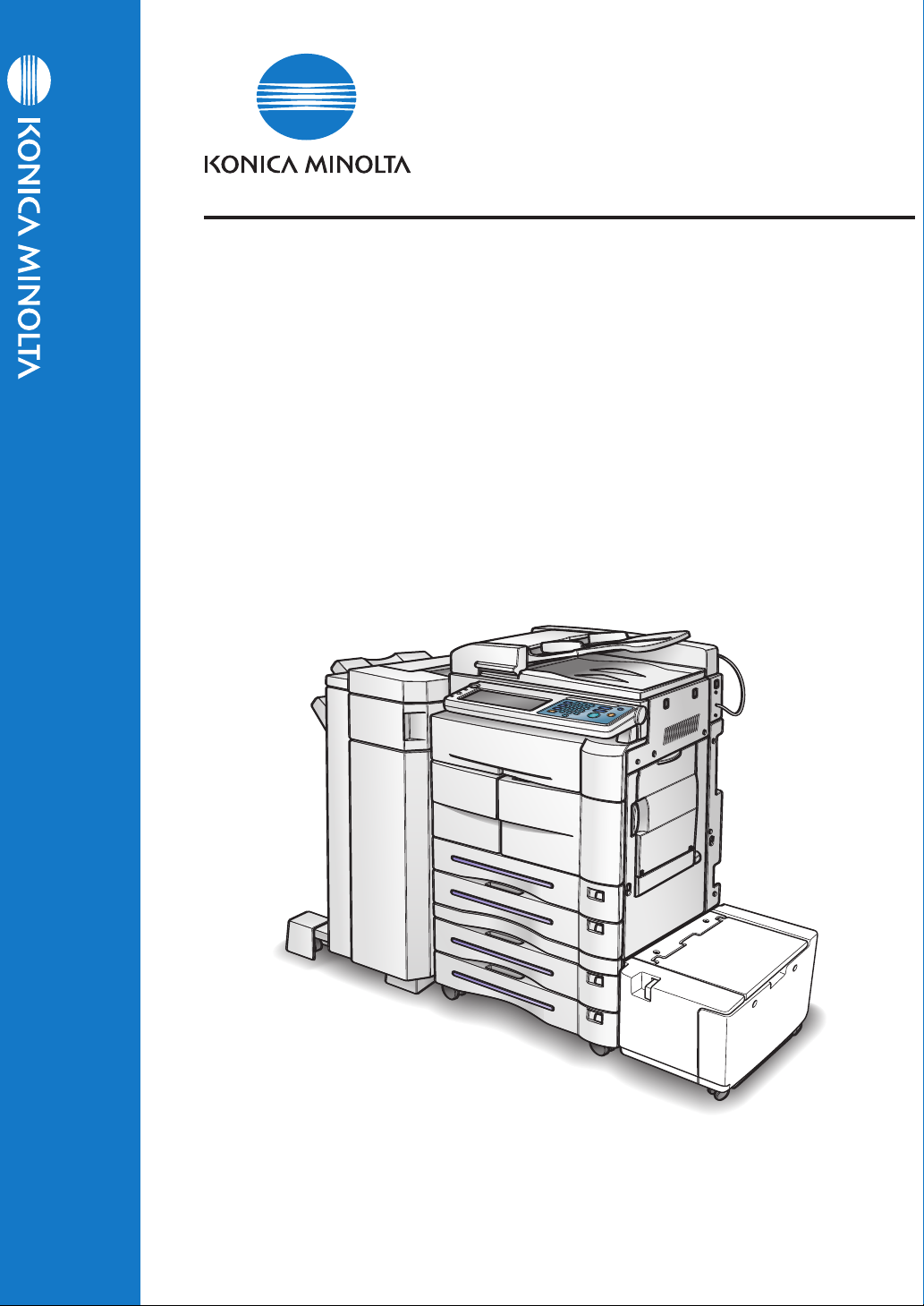
Using of this Manual
6-1. Selecting the Destination
This is the item title.
The printer fun ctions are set by displaying the printer settings screen.
Displays restrictions of combined
function s.
1 Touch the (SCAN/SERVER) button on the control panel.
2 Touch the [E-Mail] key on the LCD screen.
The sc reen dis play ed wh en an operation is executed.
This cove rs important information.
● When the Adobe Po stScr ipt driver is select ed, the docu ment size can not be set.
● Always set irregular size paper in the copier's bypass tray.
This displays buttons on the con trol
panel .
This displays the
keys on t he LCD
screen.
This cove rs ite ms
requiring attention
or wa rning s and
caution s.
3 Select [File] - [Import] - [Scan].
4 For [Drives:], select the CD-ROM drive. For folder, double-click the
[\English\Printer\Win9x_Me] folder.
● If the re are any fil es that ca nnot be deleted , logon ag ain.
vii Using of this Manual
The names of windows, dialog boxes,
and icons displayed
on the computer
scree n are written in
brackets [ ].
Folder structure is
writt en from the upper level t o lower
leve l.
Page 9
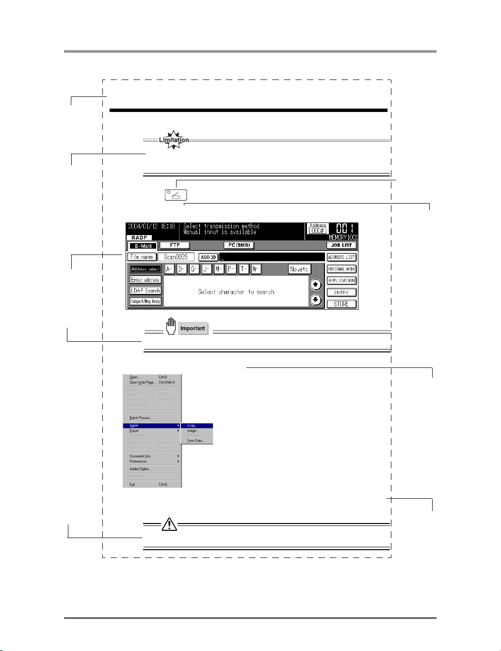
● Folder Structure on the CD-ROM
The folders included on the accompanying CD-ROM are structured as shown below.
This illustration will be helpful for locating specific folders or files.
• In this ma nual, folde r nam es and file name s are not p reced ed by the root di rectory.
• You may use the files in the English folder.
User Software CD
Windows
English
Acroread
Scanner
UserGuide
addbook_e_km_vxxx.pdf
webutila_e_km_vxxx.pdf
Japanese
Macintosh
English
Acroread
UserGuide
addbook_e_km_vxxx.pdf
webutila_e_km_vxxx.pdf
(Adobe Acrobat Reader 5.0)
(TWAIN Scanner Driver)
(Address Book Manual)
(
Web Utilities Manual)
(Adobe Acrobat Reader 5.0)
(Address Book Manual)
(
Web Utilities Manual)
Japanese
Folder structure on the CD-RO M viii
Page 10

I Outline
This section summarizes the machine’s network s canning functions and explains control
panel operations.
Chapter 1 Summary of Network Functions .. 3
Chapter 2 Before Use ..................................... 9
Chapter 3 Inputting Text .............................. 15
1
Page 11

MEMO
2
Page 12

I Outline
Chapter 1 Summary of Network Functions
This chapter summarizes the copier network fu nctions.
1-1. Network/Scanner Function Outline ..................................................... 4
1-2. Scanner Functions................................................................................ 5
1-3. Scan Data Output ..................................................................................6
3
Page 13
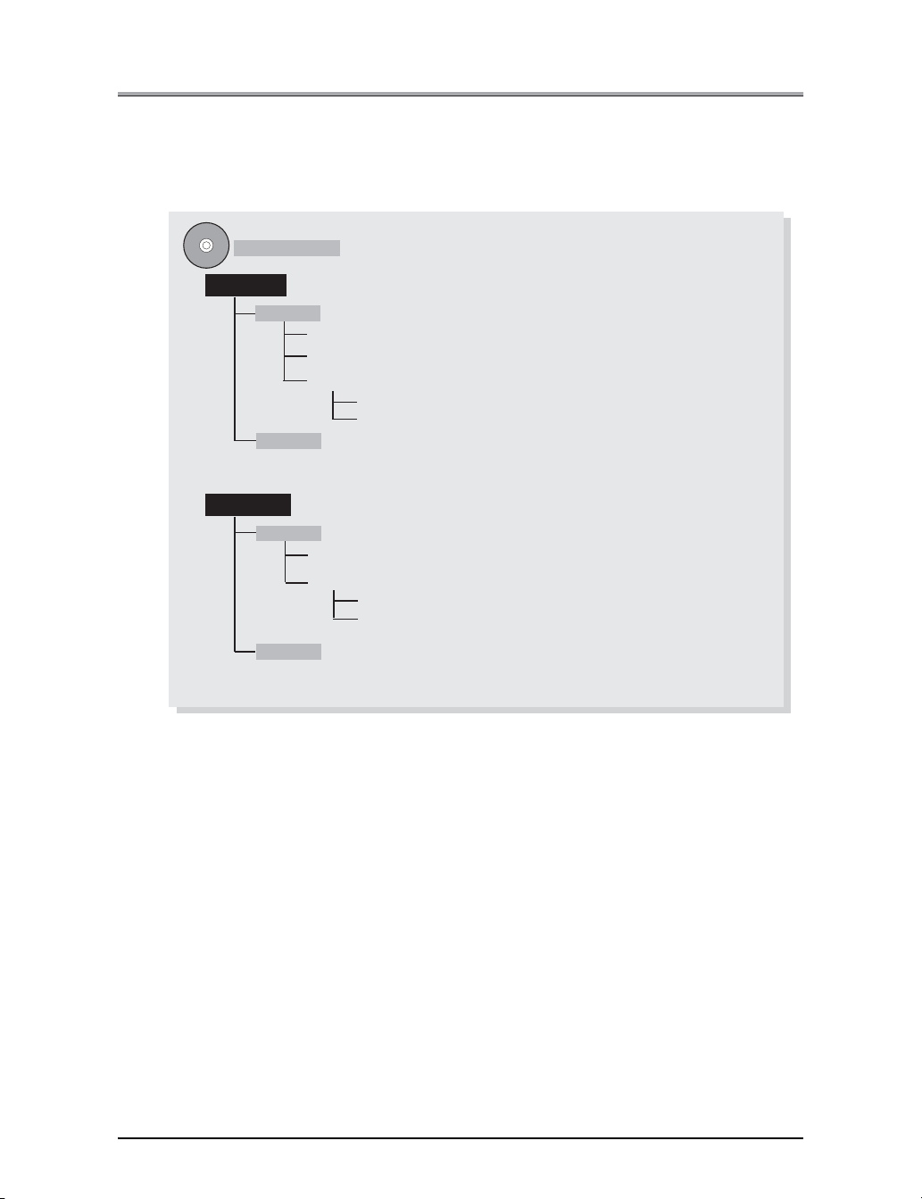
1-1. Network/Scanner Function Outline
Connection with the Network
Please connect the UTP cable (Category 5 recom mended) connected to the network to the E thernet connector (RJ-45) of the machine.
The settings required for connecting to the netw ork dep end on the environment of the network the mach ine is
connected to, the OS of the compu ters maki ng up the network, etc. Make the setti ngs requ ired to match the
environment into which this system is b eing int roduced.
Network Setting Method
There are two methods for specifying th e machine’s network settings.
Setting from t he copier control panel
Load the setting screen from the copier’s contr ol panel and set the network functions.
z For the method setting the network functions from the copier’s cont rol pane l, refer to [Chapter 4 Setting fro m the
Control Panel] ( Page 21).
Setting using the Web Utilities
This sets the network controller from a comput er connected to the network using the W eb Util ities.
z F or det ails on the Web Utilities, refer to [Chapter 5 We b Utility] ( Page 89).
I Outli ne Chapter 1 Summary of Network Functions 4
Page 14
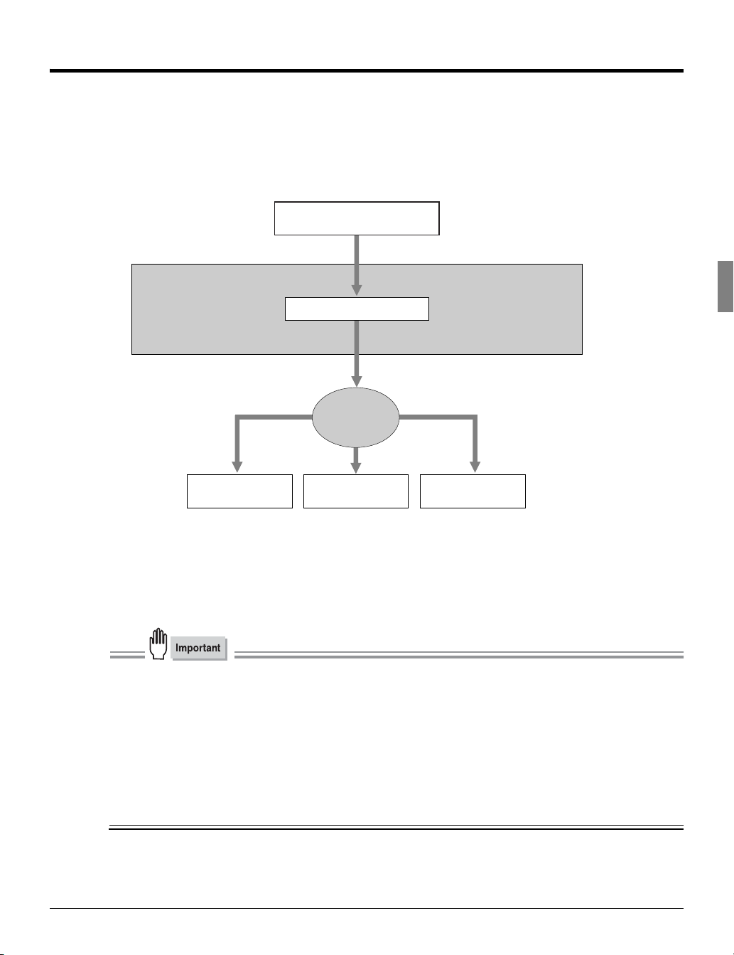
1-2. Scanner Functions
Data (scanned data) scanned from th e RAD F or from the glass bed of the copier from which the original is
scanned can be sent as an E-Mail attached f ile over the Internet (Scan to E-Mail). The data can be uploaded
to the file server (Scan to FTP) or can b e sent directly to a shared folder of PC as a file (Scan to PC (SMB)).
The machine will store the complete file and se nd out the data in packets.
For details on how to save to the copier 's hard disk (Scan to Box), refer to the User’s Guide (Document
Folder).
Scanning documents
Copier
Memory
Network
Sending with E-mail
Send to a
shared folder
Uploard to
file server
SMTP server
PC
FTP server
Before scanning documents, a destination for sending the scanned data needs to be selected from either of
the sending options: (1) [E-Mail], (2) [FT P], or (3) [PC(SMB)].
Also, [Quality], [Magnification Ratio], [Resolution], [ Continuous pages], [Erase outside of document] and
other functions can be specified at the same ti me.
● Do not send confiden tial docu ments from the copier in instance s where there is apprehe nsion that the
scanned data could be s tolen or illegally accessed .
● Depending the con dition of the network/s erver, after the s canned data is sent from the copier, the
scanned data may incur damaged. Always make sure to che ck tha t the scanned data has not been dam-
aged .
● Whe n usin g the scanner functions, connect with the computer via Ethernet. The s canner functions ca nnot be us ed from the parallel port.
● The c opier must have the appropriate IP A ddress assigned and the TC P/IP network is enabled. For
mode details on the network settings, ask the netwo rk adm inistrator.
5 I Outline Chapter 1 Summary of Network Functions
Page 15
1-3. Scan Data Output
Scanned data can be selected and sent from three de stinations, [Scan to E-Mail], [Scan to FTP] and [Scan to
PC(SMB)].
This section explains these three types of dest inations.
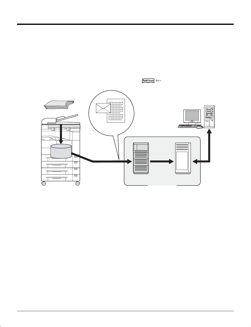
Scan to E-Mail
Scanned data can be sent to a specified E-Mail ad dress. In put the address and file name on the copier's LCD
screen and send as an E-Mail attached file.
For more information, refer to [6-1. Sele cting the Destination] ( Page 126).
Document
Copier main unit
E-mail and Scanned data
Memo ry
SMTP server
Transfer to
destination
server
Internet
E-mail
desti natio n
POP server
I Outli ne Chapter 1 Summary of Network Functions 6
Page 16
1-3. Scan Data Output
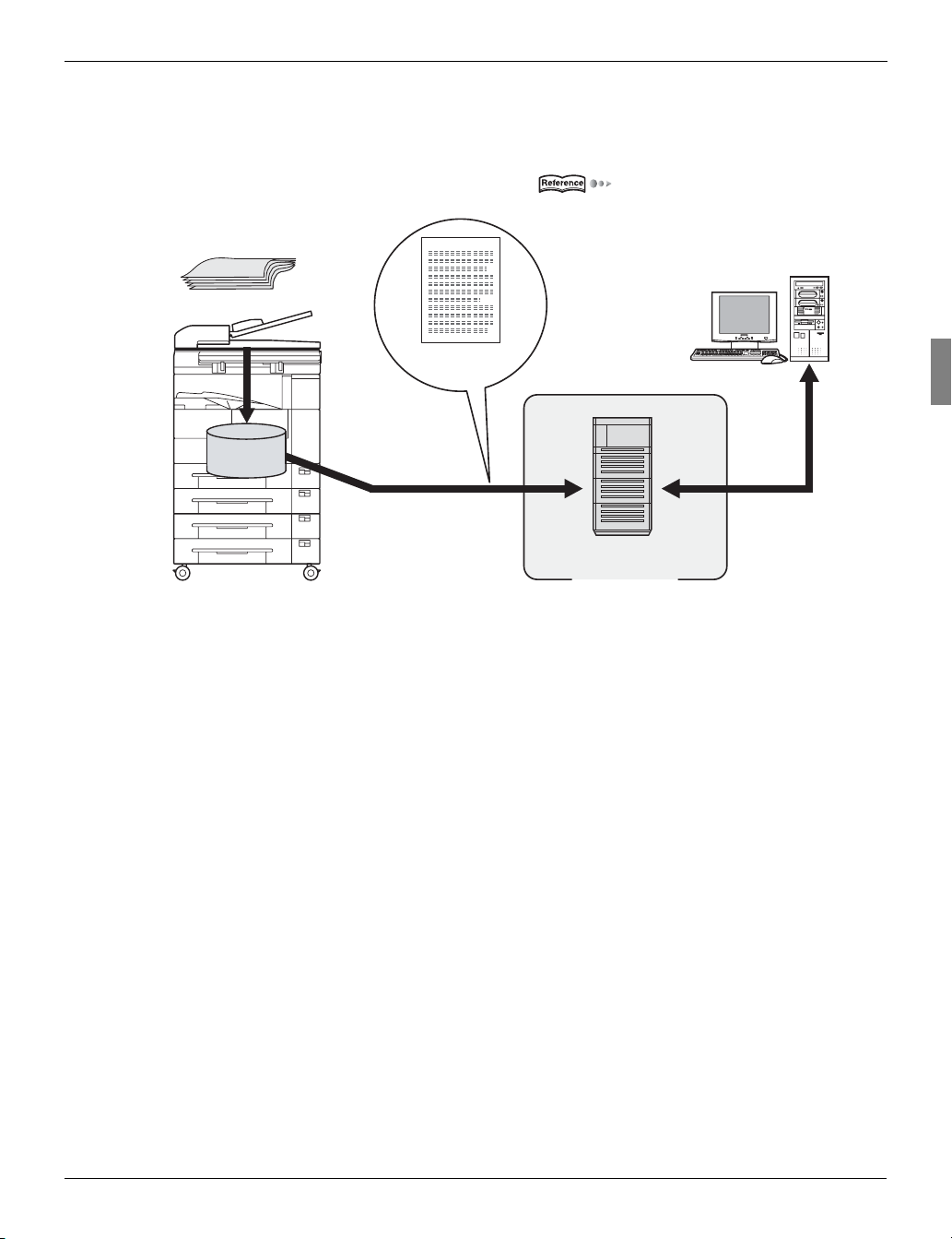
Scan to FTP
Scanned data can be uploaded to the specifie d FTP server. Input the FTP server address, l ogin password,
etc. on the copier's LCD screen.
For more information, refer to [6-1. Sele cting the Destination] ( Page 126).
Document
Copier main unit
Scanned data
Memory
Download
FTP server
Inter net
7 I Outline Chapter 1 Summary of Network Functions
Page 17
1-3. Scan Data Output
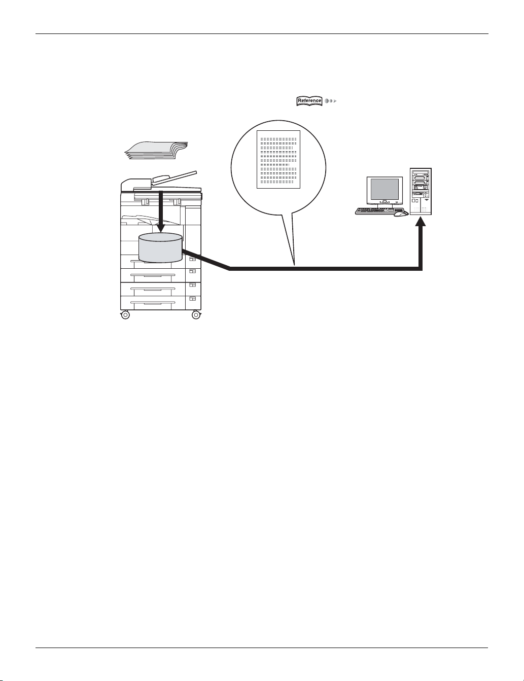
Send to a Shared Folder (Scan to PC (SMB))
Scanned data can be sent to a specified folder in a PC. Input the name and login password of the target PC
from the copier's LCD s creen.
For more information, refer to [6-1. Sele cting the Destination] ( Page 126).
Document
Copier main unit
Scanned data
Memory
Send to a shared folder
I Outli ne Chapter 1 Summary of Network Functions 8
Page 18

I Outline
Chapter 2 Before Use
This chapter explains the names of the buttons on the copier's contr ol panel a nd their functions, the contents of the LCD screen display, and the operations.
2-1. Control Panel Descriptions ................................................................10
2-2. LCD Screen..........................................................................................11
9
Page 19
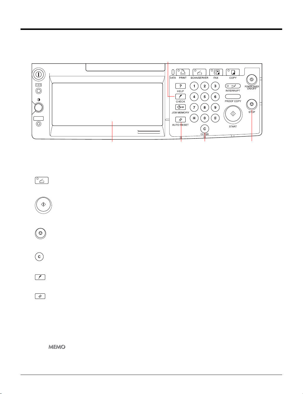
2-1. Control Panel Descriptions
The buttons on the control panel and the keys displayed on the LCD screen are used to make scanned settings.
This section explains the names and functions of the buttons used for setting operations. For information on
buttons not explained here, refer to the copier User’s Guide.
[CHECK] button
LCD screen [AUTO RESET] button [STOP] button
[CLEAR] button
LCD screen
The LCD screen displays the print controlle r status , menus used for settings, selection items, a nd other
such information. To make settings, touch the keys displayed on the screen.
(SCAN/SERVER) button
This switches between scanner/printer mode.
(START) button
This resumes the paused print processing or s tarts scanning.
(STOP) button
This stops scan processing.
(CLEAR) button
Clear the numeric characters which are entere d on the control panel.
(CHECK) button
This displays the settings check screen .
(AUTO RESET) button
This resets settings to their defaults.
Data LED
This flashes green when the copi er is receiv ing data and stays lit when data is accm ulated in the copier.
Scanner/Print er LED
This lights up green for scanner/printer mode.
z The LED lights up red when a warning or error message is displayed.
In this ca se, check the error informatio n on th e LCD s cree n and solve the erro r. For troub lesh ootin g infor matio n, refer
to the co pier User’s Guid e.
I Outli ne Chapter 2 Bef ore Use 10
Page 20
2-2. LCD Screen
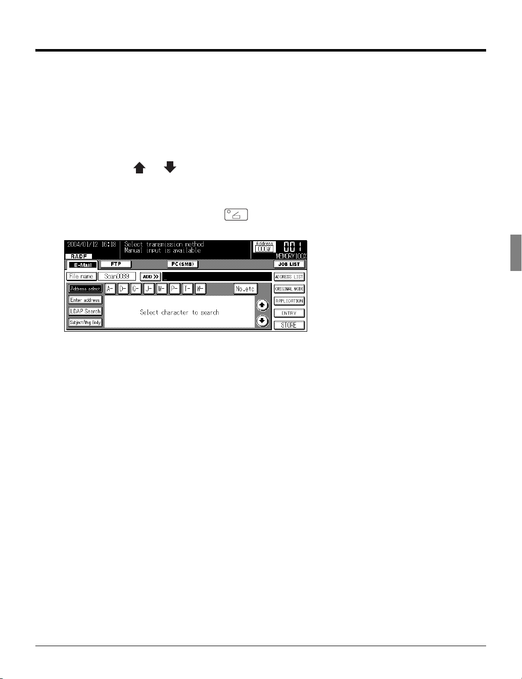
LCD Screen Operation Methods
Select items by touching the appropriat e key d isplayed on the LCD screen.
Buttons common to all setting screens
When you touch [OK], the results of the opera tion are applied.
When you touch [CANCEL], the results of the operation are cancelled.
When you touch [ ]or [ ], the screen display is switched.
Basic screen
With the copier started, if you touch the (SCAN/SERVER) butto n on the control panel, the [Scanner mode basic] screen is displayed on the LC D screen.
11 I Outl ine Chapter 2 Be fore Use
Page 21

2-2. LCD Screen
Job List Screen
When you touch the [JOB LIST] key on the [Scann er mode basic] screen, the [JOB LIST] scre en is displayed
on the LCD screen and the status of th e curren t print job or fax job can be checked.
Touch the [PRINT JOB] or [FAX JOB] key to s witch to the print job or fax job status dis play.
If there are no scheduled jobs, the column is b lank.
When the copier power is turned off, these con tents are erased.
Job List Contents
JOB No.
The job number (001 to 999) is display ed.
MODE
This displays the job processing mode (copier/printer/scanner).
STATUS
This displays the status of each job.
Error : An er ror occurred.
Outputting : The data is being copied/p rinted/scanned.
No paper : There is no paper in the tray (copy/pri nt mode ).
Stopped : Stopp ed, interrupted, waiting jam processing (each m ode).
Scanning : The docume nt is be ing scanned.
Waiting output : The job has been scheduled and is waiting fo r copy/print/scan output.
Converting : The data is being converted.
Processing : An E -mail message for "Scan to E-M ail" is being created.
NAME
Displays the JOB Name.
TOTAL PAGE (s)
This displays the number of output pag es (1 to 999) set for the job.
PAGE(s) LEF T
This displays the number of pages left to be ou tput (1 to 9999).
Number of pages left to be output = Number of pages (per cop y) x Number of copies set
z If the number of pages left to be output is greater than 99 99, [*9999] is di splayed.
I Outli ne Chapter 2 Bef ore Use 12
Page 22
2-2. LCD Screen
MINUTE(s) TO GO
This displays the time remaining until jo b completion in minutes (1 to 999).
z T he displaye d tim e is an approximation.The actual time may be somewhat longer o r sho rter than the time displaye d.
z I f the t ime re main ing is greater th an 9 99 minutes, [*99 9] is disp layed.
z If the time remaining is le ss than 1 minute, [<1] is displayed.
Changing Job Order
1 Touch the [ ], [ ] key to select the job to be processed first.
2 Touch the [ADVANCE] key.
→ The selected job is displayed inverted and is moved to next after the job currently be ing outp ut.
Job Deletion
1 Touch the [ ], [ ] key to select the job to delete.
2 Touch the [DELETE] key.
→ The selected job is deleted from the copier's memory.
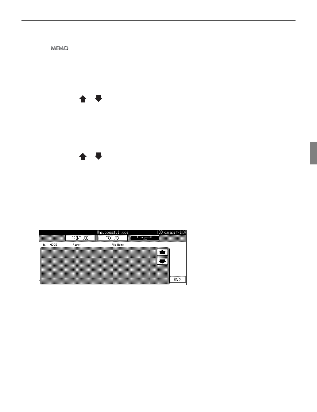
Unsuccessful Job List
Touch the [Unsuccessful jobs] key to d isplay a list of jobs that have yet to be complete d.
If there are any incomplete scanning jo bs or pr inting jobs they will be displayed here.
This data will be erased once the main power is turned off to the machine.
Unsuccessful Job List Data
MODE
E-mail, FTP, Box, PC(SMB)
File Name
Factor
Cancelled, Auto Delete, etc.
When [Error N**] is displayed in this me nu, ple ase refer to Troubleshooting, Chapter 7 .
13 I Outl ine Chapter 2 Be fore Use
Page 23

MEMOMEMO
14
Page 24

I Outline
Chapter 3 Inputting Text
This chapter explains how to input text for nam es and descriptions.
3-1. Inputting Text ......................................................................................16
15
Page 25
3-1. Inputting Text
This section explains the operation me thod for inpu tting text, used for operations such as registering name
and entering E-mail addresses.
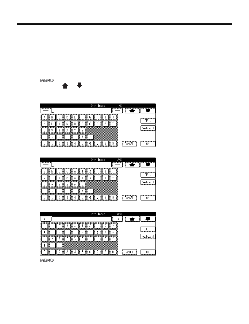
Data Input Screen
Normal Input Screen
There are three kinds of Normal Input screen a s below.
z Touch the [ ] or [ ] key to switch to the input chara cter type scree n.
z Touch the [Normal ] key on the keyboard inp ut screen to swit ch to QWERTY in put mode.
Uppercase le tter input screen
Lowercase le tter input screen
Number and s ymbol input screen
z When you touch the [DEL.] key on the LCD screen, the input characters are deleted one at a time.
I Outli ne Chapter 3 Inputting Text 16
Page 26
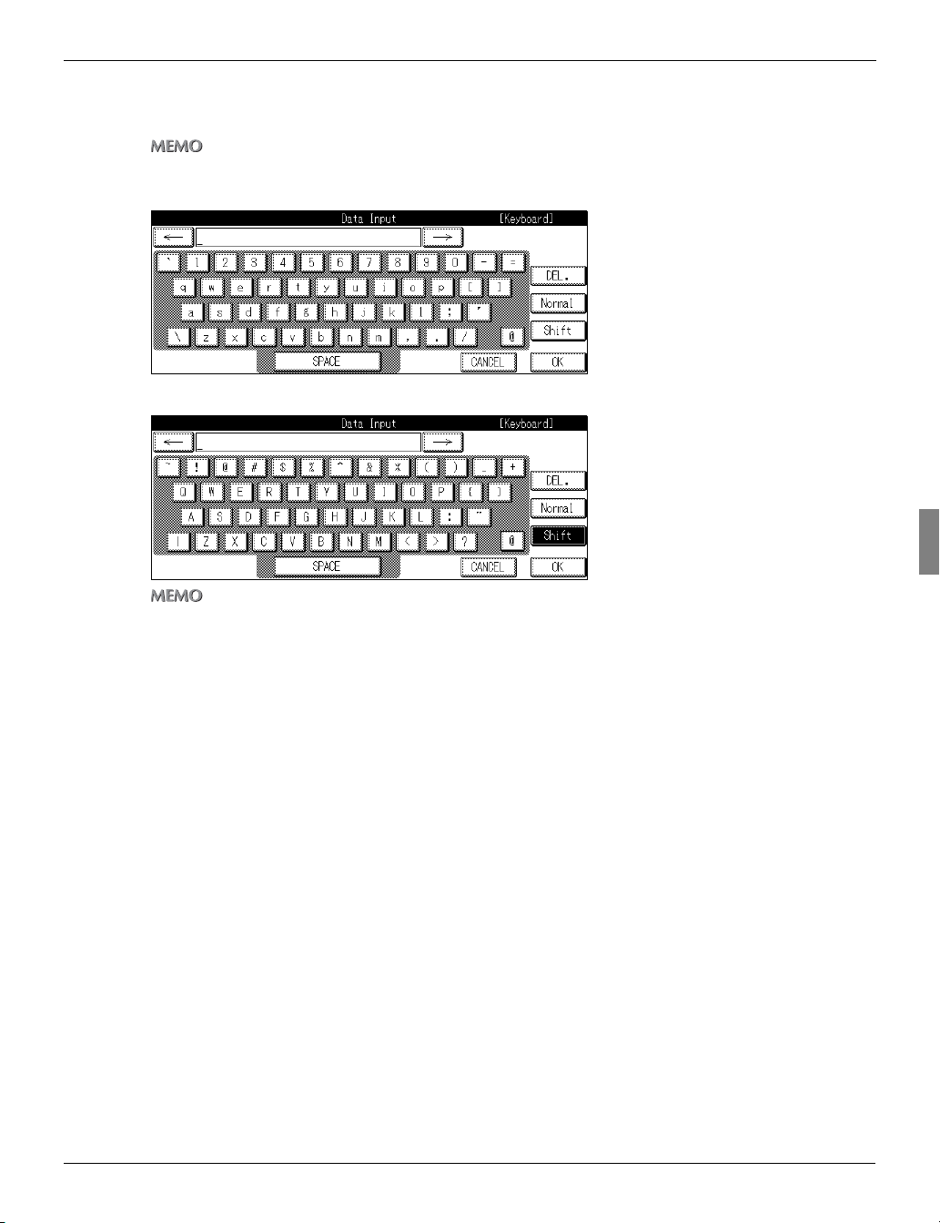
Keyboard Input Screen
There are two kinds of Keyboard scree n as below.
z Touch the [Keyboard] key o n the normal inp ut screen to swit ch to QWERTY in put mode.
Lowercase le tter input screen
Uppercase le tter input screen
3-1. Inputting Text
z Touch the [Shift] key also t o switch to the input character type sc reen.
z Touch the [Normal ] key whi le in QWERTY input mode to revert to the previous input mode.
17 I Outli ne Chapter 3 Inputting Text
Page 27

3-1. Inputting Text
Inputting Text
1 Select a type of the [Data Input] scr een.
2 Touch the letter keys on the LCD sc reen to input the letters.
3 Repeat the step 1 and 2.
4 Touch the [OK] on the LCD screen.
z When you touch the [DEL.] key on the LCD screen, the input characters are deleted one at a time.
I Outli ne Chapter 3 Inputting Text 18
Page 28

II Network Setup Administrators only
This section explains how to proceed with network settings.
Chapter 4 Setting from the Control Panel ..21
Chapter 5 Web Utility....................................89
19
Page 29

MEMO
20
Page 30

II Network Setup - Administrators only
Chapter 4 Setting from the Control Panel
This chapter explains the method fo r makin g the network settings from the Copi er’s co ntrol
panel.
4-1. Network Setup List.............................................................................. 22
4-2. Method for Setting Network from Control Panel ..............................23
4-3. TCP/IP Setup........................................................................................ 27
4-4. NetWare Setup.....................................................................................33
4-5. AppleTalk Setup ..................................................................................41
4-6. IPP Setup ............................................................................................. 44
4-7. FTP Setup ............................................................................................54
4-8. E-Mail (SMTP) Setup ...........................................................................57
4-9. E-Mail (POP) Setup.............................................................................. 63
4-10. E-Mail Extended Config ....................................................................69
4-11. Device Setup......................................................................................72
4-12. List Print............................................................................................. 75
4-13. PC(SMB) Setup..................................................................................76
4-14. LDAP Setup .......................................................................................77
21
Page 31

4-1. Network Setup List
This explains the settings required when conne cting the copier to the network.
Set each setting item to match the en vironm ent of the network to which the copie r is con nected. When
changing the setting for each item, ask the net work administrator.
TCP/IP Setup ( Page 27
This sets the items required for communicating with TCP/IP.
NetWare Setu p ( Pag e 33)
This sets the items required for communicating with NetWare.
AppleTalk Se tup ( Page 4 1)
This sets the items required for communicating with AppleTalk.
IPP Setup ( Page 44)
This sets the items required for IPP Prin ting.
FTP Setup ( Page 54)
This sets the items for sending scanned image s from the Copier to the FTP server.
E-Mail (SMTP ) Setup ( Page 57)
This sets the items required for sending scanned images from the Copier as E-mail attachments.
E-Mail (POP) Setup ( Pag e 63)
This sets the items required to use the POP se rver.
E-Mail Extended Con fig ( Page 69)
This is used to set the Reception/Dispo sition notifications for E-mail when the Internet fax is used.
Device Setup ( Page 72)
This sets the interface items.
List Print ( Page 75)
This prints out the setup list.
PC(SMB) Set up ( Page 76)
Sets the items required for sending scanned d ata to a shared folder of PC.
LDAP Setup ( Page 77)
Sets the items required for accessing th e LDAP server to acquire a mail address for [S can to E-Mail].
II Network Setup - Administrators only 22
Chapter 4 Setting from the Con trol Panel
Page 32

4-2. Method for Setting Network from Control Panel
This explains how to set the network connectio n using the control panel and LCD screen.
● After the netw ork settings have been changed, a message "To valid the data, please turn OFF main SW
and ON" may appear on the touch panel. If this me ssage is displaye d, be sure to switch the main power
for the copier OFF and wait at least 10 seconds, then turn it back ON.
1 Press the (COPY) button on the control panel.
→ The [Copy basic mode] screen is displa yed on the LCD screen.
2 Press the (HELP) button on the control panel, then press the [Key Ope mode] key.
→ The [HELP MODE] screen is displayed on the LCD screen.
23 II Network Setup - Administrators only
Chap ter 4 Setting fro m the Con trol Panel
Page 33

4-2. Method for Setting Network from Control Panel
3 If a password is set, the key operator's password input screen is displayed. Touch the
[Password] key and input the password in the [Data Input] screen. Then, touch the
[OK] key or input the password (up to 8 digits) using the ten-keys.
4 Touch the [OK] key on the [Password Input] screen.
z T he Key oper ator password is set by you r serv ice re prese ntati ve. If the key o perato r password has been set, the key
operator should keep the password safe on his/her own responsibility.
z For the Key operator password, please ask your service representative.
z I f the [ Enhan ced S ecurity] is use d, the password s houl d be 8 digits.
5 Touch the [OK] key.
→ The [Key operator mode] screen is disp layed o n the LCD screen.
z T his screen may not be displayed, de pend ing on whi ch o ption s ar e set for [4.FAX], [5.Pri nter] and [6.Do cument
Folder].
II Network Setup - Administrators only 24
Chapter 4 Setting from the Con trol Panel
Page 34

4-2. Method for Setting Network from Control Panel
6 Touch the [2.Network] key.
The following settings are made on th e [Network setting] screen.
TCP/IP Setup Page 27
NetWare Setup Page 33
AppleTalk Setup Page 41
IPP Setup Page 44
FTP Setup Page 54
E-Mail (SMTP) Setup Page 57
E-Mail (POP) Setup Page 63
E-Mail Extended Config Page 69
Device Setup Page 72
List Print Page 75
PC (SMB) Setup Page 76
LDAP Setup Page 77
z [ 8. E-Mail Extended Config] is enabled only when the optional hard disk is connected.
7 Select the item to set by touching it.
25 II Network Setup - Administrators only
Chap ter 4 Setting fro m the Con trol Panel
Page 35

4-2. Method for Setting Network from Control Panel
8 Set each item and when setting of all the items is complete, touch the [OK] key.
→ The display returns to the [Network set ting] screen.
z Touching [CANCEL] will re turn you to the [Network setting] screen without a ny of th e changes taking effect.
IP Address Settings
There are two methods for setting the I P address etc. for the network controller.
Assigning the IP address automatically with the DHCP server
When managing IP addre sses with a DHCP server on the network, the re is no need to set a unique IP
address for the network controller. The IP address can be assigned autom atically from the DHCP
server.
Setting a uniq ue IP address for the network controller
When setting individual IP addresses for eq uipmen t connected to the network, the IP address a ssigned
to the network controller is manually input. In t his case , it is also necessary to set the s ub-net mask and
other information with manual input.
z F or det ails on management m ethod s for netw ork IP addresses etc. , check with your net work admini strator.
z F or det ails on making n etwork settings manua lly, check with the n etwork administ rator.
z W hen making ne twork sett ings manuall y, in a dditi on to th e met hod ex plained here using the control panel, you can
also use a web utility. For details, refer to the Web Utilities User’s Guide.
II Network Setup - Administrators only 26
Chapter 4 Setting from the Con trol Panel
Page 36

4-3. TCP/IP Setup
The information required for using the p rint con troller in the TCP/IP environment is set.
1 Touch the [1.TCP/IP Setup] key on [Network setting] screen.
→ The [TCP/IP Setup] screen is displayed .
z For details on the procedure for di splaying the [Network setti ng] screen, refer to [ 4-2.Meth od for Setting Netwo rk from
Control Panel] ( Page 23).
Use [TCP/IP] screen to access the fo llowing :
[TCP/IP] screen 1/3
Enable TCP/IP Page 28
IP Address Page 28
Subnet Mask Page 28
Default Gateway Page 29
Enable DHCP Page 29
[TCP/IP] screen 2/3
Preferred DNS Server Page 30
Other DNS Server Page 30
RAW Port Number Page 31
[TCP/IP] screen 3/3
DNS Host Name Page 32
DNS Domain Name Page 32
z Use [ ] and [ ] to switch t he screen.
2 Touch [OK] key.
→ The display returns to the [Network set ting] screen.
z Touching [CANCEL] will re turn you to the [Network setting] screen without a ny of th e changes taking effect.
27 II Network Setup - Administrators only
Chap ter 4 Setting fro m the Con trol Panel
Page 37

4-3. TCP/IP Setup
TCP/IP Setup (Part 1 of 3)
1 Access the [TCP/IP Setup] screen (1/3) from the [Network setting] screen.
z For details on the procedure for di splaying the [Network setti ng] screen, refer to [ 4-2.Meth od for Setting Netwo rk from
Control Panel] ( Page 23).
z Use [ ] and [ ] to switch t he screen.
Enable TCP/IP
This sets whether to enable TCP/IP.
1 To disable TCP/IP settings, touch the [OFF] k ey on the LCD Screen. To enable them to uch
the [ON] key.
IP Address
The IP Address is registered on the Ne twork Controller.
1 Touch the [IP Address] key.
2 Use the keys on the control panel to input the IP Address.
Specify four sets of three digit numbers, sepa rated by the periods as the IP Address.
When you touch
z When using a DHCP server for IP Address management, the IP Address acquired with DHCP is displayed.
[] or [] the cursor moves to the left and right.
Subnet Mask
This inputs the subnet mask for the ma chine’s network.
1 Touch the [Subnet Mask] key.
2 Use the keys on the control panel to input the subnet mask.
Specify four sets of three digit numbers, sepa rated by the periods as the subnet mask.
When you touch
z When using a DHCP server for subnet mask management, the subnet mask acquired with DHCP is displayed.
[] or [] the cursor moves to the left and right.
II Network Setup - Administrators only 28
Chapter 4 Setting from the Con trol Panel
Page 38

4-3. TCP/IP Setup
Default Gateway
This inputs the gateway for the machin e’s netw ork.
1 Touch the [Default Gateway] key.
2 Use the keys on the control panel to input the default gateway address.
Specify four sets of three digit numbers, separated by th e periods as the default gateway address.
When you touch [] or [] the cursor m oves to the left and right.
z When using a DHCP server for default gateway address management, the default gateway address acquired with
DHCP is displayed.
Enable DHCP
This sets whether or not to automatic ally acq uire IP Addresses and other such info rmation from a
DHCP (Dynamic Host Configuration Pro tocol) server.
1 Touch the [ON] or [OFF] key on the [Enable DHCP Setting].
[ON] :W hen acquiring information from a DHCP server
[OFF] :When not acquiring informa tion from a DHCP Server
z The factory default setting is [ON].
29 II Network Setup - Administrators only
Chap ter 4 Setting fro m the Con trol Panel
Page 39

4-3. TCP/IP Setup
TCP/IP Setup (Part 2 of 3)
1 Use [ ] or [ ] to access [TCP/IP Setup] screen (2/3) from screen (1/3).
z For details on the procedure for di splaying the [Network setti ng] screen, refer to [ 4-2.Meth od for Setting Netwo rk from
Control Panel] ( Page 23).
Preferred DNS Server
Sets the address for the preferred DNS Server
1 Touch the [Preferred DNS server] k ey.
2 Use the keys on the control panel to input the DNS Address.
Specify four sets of three digit numbers, separeted by th e periods as the preferred DNS server.
When you touch [] or [] the cursor m oves to the left and right.
Other DNS Server
Sets the address for the other DNS Server
1 Touch the [Other DNS server] key.
Specify four sets of three digit numbers, separated by th e periods as the alternate DNS server.
When you touch [] or [] the cursor m oves to the left and right.
2 Use the keys on the control panel to input the DNS Address.
II Network Setup - Administrators only 30
Chapter 4 Setting from the Con trol Panel
Page 40

4-3. TCP/IP Setup
RAW Port Number
Allows you to assign a Port Code.
● Changing the Port Code in an impr oper manner can result in dam age to the netwo rk. Do no t change the
Port Code unless it is necessary to do so.
1 Touch the [RAW Port Number] key.
2 Using the keys on the control pane l, input a Port Code number between 1-65535 .
31 II Network Setup - Administrators only
Chap ter 4 Setting fro m the Con trol Panel
Page 41

4-3. TCP/IP Setup
TCP/IP Setup (Part 3 of 3)
1 Use the [ ] or [ ] to access [TCP/IP Setup] screen (3/3) from the screen (2/3).
z For details on the procedure for di splaying the [Network setti ng] screen, refer to [ 4-2.Meth od for Setting Netwo rk from
Control Panel] ( Page 23).
DNS Host Name
This sets the DNS Host name.
1 Touch the [DNS Host Name] key.
2 Using the data input screen, input t he DNS Host name.
DNS Domain Name
This sets the DNS Domain name.
1 Touch the [DNS Domain Name] key .
2 Using the data input screen, input t he DNS Domain name.
z For details on chara cter input, refer to [3-1.Inputting Text] ( Page 16).
II Network Setup - Administrators only 32
Chapter 4 Setting from the Con trol Panel
Page 42

4-4. NetWare Setup
The information required for using the p rint con troller in the NetWare network environm ent is s et.
1 Touch the [2.NetWare Setup] key on [Network setting] screen.
→ The [NetWare Setup] screen is displaye d.
z For details on the procedure for di splaying the [Network setti ng] screen, refer to [ 4-2.Meth od for Setting Netwo rk from
Control Panel] ( Page 23).
Use [NetWare Setup] screen to acce ss the f ollowing:
[NetWare Setup] screen 1/3
Enable NetWare Page 35
Ethernet Frame Type Page 35
Print Server Name Page 35
Print Server Password Page 36
[NetWare Setup] screen 2/3
File Server Page 37
NDS Context Page 37
NDS Tree Page 38
[NetWare Setup] screen 3/3
Operating Mode Page 39
Printer Number Page 39
[NetWare Setup : Detail] screen
Print Queue Scan Rate Page 40
Disable Bindery Page 40
z Use [ ] and [ ] to switch t he screen.
z For details on NetW are sett ings, re fer to the NetWare User’ s Guide.
33 II Network Setup - Administrators only
Chap ter 4 Setting fro m the Con trol Panel
Page 43

4-4. NetWare Setup
2 Touch [OK] key.
→ The display returns to the [Network set ting] screen.
z Touching [CANCEL] will re turn you to the [Network setting] screen without a ny of th e changes taking effect.
II Network Setup - Administrators only 34
Chapter 4 Setting from the Con trol Panel
Page 44

4-4. NetWare Setup
NetWare setup (Part 1 of 3)
1 Access to [NetWare Setup] screen (1/3) from [Network setting] screen.
z For details on the procedure for di splaying the [Network setti ng] screen, refer to [ 4-2.Meth od for Setting Netwo rk from
Control Panel] ( Page 23).
z Use [ ] and [ ] to switch t he screen.
Enable NetWare
This sets whether or not to enable the m achine ’s NetWare capabilities in the network e nvironment.
1 To disable NetWare settings, touch the [O FF] key. To enable them touch the [ON] key.
[ON] :Used in the NetWare environment
[OFF] :Not used in the NetWare environment
Ethernet Frame Type
This sets the frame type used by the m achine.
1 Touch the [EDIT] key on the [Ethern et Fram e Type] screen.
[EDIT] :Choose from below
[Auto-Sense]→ [802.2]→[802.3]→[Ethernet II]→[802.2 SNMP]→[Auto-Sense]
z The factory default setting is [Auto-Sense].
2 Touch [OK] key.
Print Server Name
This sets the Print Server name assign ed to th e Network Controller.
1 Touch the [Print Server Name] key.
2 Using the [Data Input] screen, input the Pr int Server name.
3 Touch [OK] key.
→ The screen will return to [NetWare Setup].
35 II Network Setup - Administrators only
Chap ter 4 Setting fro m the Con trol Panel
Page 45

4-4. NetWare Setup
Print Server Password
This sets the password necessary for th e Print Server to login to the File Server.
1 Touch the [Password] key.
2 Using the [Data Input] screen, inpu t the pa ssword.
3 Touch [OK] key.
→ The screen will return to [NetWare Setup].
II Network Setup - Administrators only 36
Chapter 4 Setting from the Con trol Panel
Page 46

4-4. NetWare Setup
NetWare setup (Part 2 of 3)
1 Use [ ] or [ ] to access to [NetWare Setup] screen (2/3) from screen (1/3).
z For details on the procedure for di splaying the [Network setti ng] screen, refer to [ 4-2.Meth od for Setting Netwo rk from
Control Panel] ( Page 23).
File Server Name
This sets the File Server name that the Print S erver will log in with.
1 Touch the [File Server] key.
2 Using the [Data Input] screen, input the fil e sever name.
3 Touch [OK] key.
→ The screen will return to [NetWare Setup].
NDS Context Name
This sets the NDS (Novell Directory Se rvice) N ame.
1 Touch the [NDS Context] key.
2 Using the [Data Input] screen, inpu t the ND S Context name.
3 Touch [OK] key.
→ The screen will return to [NetWare Setup].
37 II Network Setup - Administrators only
Chap ter 4 Setting fro m the Con trol Panel
Page 47

4-4. NetWare Setup
NDS Tree
This sets the NDS Tree Name.
1 Touch the [NDS Tree] key.
2 Using the [Data Input] screen, input the ND S Tree name.
3 Touch [OK] key.
→ The screen will return to [NetWare Setup].
II Network Setup - Administrators only 38
Chapter 4 Setting from the Con trol Panel
Page 48

4-4. NetWare Setup
NetWare setup (Part 3 of 3)
1 Use the [ ] or [ ] to access [NetWare Setup] screen (3/3) from screen (2/3).
z For details on the procedure for di splaying the [Network setti ng] screen, refer to [ 4-2.Meth od for Setting Netwo rk from
Control Panel] ( Page 23).
Operating Mode
This sets up the Operation Mode.
1 Touch the [PServer] or [RPrinter] ke y.
[PServer] :Select when using the PServer mode.
[RPrinter] :Select when using the RPrin ter mode.
Printer Number
This sets the Printer Number.
1 Using the control panel, enter the P rinter N umber between 0 and 255.
39 II Network Setup - Administrators only
Chap ter 4 Setting fro m the Con trol Panel
Page 49

4-4. NetWare Setup
Perform the detailed setup for NetWare
1 Touch the [DETAIL] key on the [NetWare Setup] screen.
→ [NetWare Setup :Detail] Screen will be display ed.
z For details on the procedure for di splaying the [Network setti ng] screen, refer to [ 4-2.Meth od for Setting Netwo rk from
Control Panel] ( Page 23).
Print Queue Scan Rate
This sets the time interval for searching the Print Queue.
1 Using the control panel, enter the ti me inte rnal between 1 and 65535.
Disable Bindery
This sets whether or not to enable bind ery service for NetWare 4.x or later.
1 Touch the [YES] or [NO] keys on th e [Disa ble Bindery] menu.
[YES] :Disables Bindery Service
[NO] :En ables Bindery Service
2 Touch [OK] key.
→ The screen will return to [NetWare Setu p].
z Touching [CANCEL] will re turn you to the [Network setting] screen without a ny of th e changes taking effect.
II Network Setup - Administrators only 40
Chapter 4 Setting from the Con trol Panel
Page 50

4-5. AppleTalk Setup
Set the information required for using th e mach ine in the AppleTalk network environme nt.
1 Touch the [3.AppleTalk Setup] key on [Network setting] screen.
→ The [AppleTalk Setup] screen is displa yed.
z For details on the procedure for di splaying the [Network setti ng] screen, refer to [ 4-2.Meth od for Setting Netwo rk from
Control Panel] ( Page 23).
Use [AppleTalk Setup] screen to acc ess the following:
Enable AppleTalk Page 42
Printer Name Page 42
Zone Name Page 43
2 Touch [OK] key.
→ The display returns to the [Network set ting] screen.
z Touching [CANCEL] will re turn you to the [Network setting] screen without a ny of th e changes taking effect.
41 II Network Setup - Administrators only
Chap ter 4 Setting fro m the Con trol Panel
Page 51

4-5. AppleTalk Setup
AppleTalk setup
1 Access the [AppleTalk Setup] screen from [Network setting] screen.
z For details on the procedure for di splaying the [Network setti ng] screen, refer to [ 4-2.Meth od for Setting Netwo rk from
Control Panel] ( Page 23).
Enable AppleTalk
This sets whether or not to enable App leTalk.
1 On the [AppleTalk Setup] screen, touch ei ther the [ON] or [OFF] key.
[ON] :Enables AppleTalk
[OFF] :Disables AppleTalk
z The factory default setting is [ON].
Printer Name
This sets the Machine’s name to be display ed on the AppleTalk network.
1 Touch the [Printer Name] key.
2 Using the data input screen, input t he Prin t Name.
3 Touch [OK] key.
z T he Prin ter Name should not excee d 32 chara cters .
z For details on chara cter input, refer to [3-1.Inputting Text] ( Page 16).
II Network Setup - Administrators only 42
Chapter 4 Setting from the Con trol Panel
Page 52

Zone Name
This specifies the zone that the print co ntroller is connected to.
1 Touch the [Zone Name] key.
2 Using the data input screen, input t he Prin t Name.
3 Touch [OK] key.
z The Zone Name should not exceed 32 characters.
z For details on chara cter input, refer to [3-1.Inputting Text] ( Page 16).
z I f there is n o zone (whe n usi ng a network wi th no shielded router), leave thi s column blank.
4-5. AppleTalk Setup
43 II Network Setup - Administrators only
Chap ter 4 Setting fro m the Con trol Panel
Page 53

4-6. IPP Setup
This sets the IPP features.
1 Touch the [4.IPP Setup] key on the [Network setting] screen.
→ The [IPP Setup] screen will be displaye d.
z For details on the procedure for di splaying the [Network setti ng] screen, refer to [ 4-2.Meth od for Setting Netwo rk from
Control Panel] ( Page 23).
Use [IPP Setup] screen to access the follow ing:
[IPP Setup] screen 1/4
Enable IPP Page 46
Accept IPP Job Page 46
[IPP Setup] screen 2/4
Message from Operator Page 47
Job Size Page 47
[IPP Setup] screen 3/4
Operation Supported Page 48
[IPP Setup] screen 4/4
Supported Document Format Page 49
[IPP Setup] Printer information scree n
Printer Related Information Page 53
z Use [ ] and [ ] to switch t he screen.
II Network Setup - Administrators only 44
Chapter 4 Setting from the Con trol Panel
Page 54

2 Touch [OK] key.
→ The display returns to the [Network set ting] screen.
z Touching [CANCEL] will re turn you to the [Network setting] screen without a ny of th e changes taking effect.
4-6. IPP Setup
45 II Network Setup - Administrators only
Chap ter 4 Setting fro m the Con trol Panel
Page 55

4-6. IPP Setup
IPP setup (Part 1 of 4)
1 Access to [IPP Setup] screen (1/4) from [Network setting] screen.
z For details on the procedure for di splaying the [Network setti ng] screen, refer to [ 4-2.Meth od for Setting Netwo rk from
Control Panel] ( Page 23).
z Use [ ] and [ ] to switch t he screen.
Enable IPP
This setting activates and deactivates I PP.
1 Touch either the [ON] or [OFF] key on the [Enable IPP] screen.
[ON] :En ables IPP
[OFF] :Disables IPP
Accept IPP Job
1 Touch either the [YES] or [NO] key on the [Accept IPP job] screen.
[YES] :Sets the machine to accept IPP job
[NO] :Se ts the machine to decline IPP job
z The factory default setting is [YES].
II Network Setup - Administrators only 46
Chapter 4 Setting from the Con trol Panel
Page 56

IPP setup (Part 2 of 4)
1 Use [ ] or [ ] to access to [IPP Setup] screen (2/4) from screen (1/4).
z For details on the procedure for di splaying the [Network setti ng] screen, refer to [ 4-2.Meth od for Setting Netwo rk from
Control Panel] ( Page 23).
Message from Operator
This sets the operator message.
1 Touch the [Message from Operator] key.
4-6. IPP Setup
2 Using the [Data Input] screen, input the m essage.
3 Touch the [OK] key.
Job Size
This sets the job size.
1 Using the control panel, enter a val ue betw een 0 and 4294967.
z The factory default setting is [42949 67].
47 II Network Setup - Administrators only
Chap ter 4 Setting fro m the Con trol Panel
Page 57

4-6. IPP Setup
IPP setup (Part 3 of 4)
1 Use [ ] or [ ] to access to [IPP Setup] screen (3/4) from screen (2/4).
z For details on the procedure for di splaying the [Network setti ng] screen, refer to [ 4-2.Meth od for Setting Netwo rk from
Control Panel] ( Page 23).
Operation Support Information
This sets operation support information .
1 Activate/Deactivate each task by to uching the [ON] or [OFF] key.
Print Job
Validate Job
Cancel Job
Get Job Attributes
Get Jobs
Get Printer Attributes
II Network Setup - Administrators only 48
Chapter 4 Setting from the Con trol Panel
Page 58

IPP setup (Part 4 of 4)
1 Use [ ] or [ ] to access to [IPP Setup] screen (4/4) from screen (3/4).
z For details on the procedure for di splaying the [Network setti ng] screen, refer to [ 4-2.Meth od for Setting Netwo rk from
Control Panel] ( Page 23).
Supported Document Format
This sets the types of documents suppo rted.
1 [Default] selection menu
Touch the [ON] key under the [Default] category for the do cument formats to be supported by
default.
4-6. IPP Setup
z Selecting [O N] in the [Defa ult] sel ection menu will automatically set the format [ON] in the [Docume nt Format] menu.
2 [Document Format] menu
This selects which document formats are to b e supported outside of default settings.
[ON] :Su pports the format
[OFF] :Does not support th e format
49 II Network Setup - Administrators only
Chap ter 4 Setting fro m the Con trol Panel
Page 59

4-6. IPP Setup
Printer Related Infomation
1 Touch [Printer Info] on the [IPP Setup] screen.
→ The [Printer Information] screen will be display ed.
z For details on the procedure for di splaying the [Network setti ng] screen, refer to [ 4-2.Meth od for Setting Netwo rk from
Control Panel] ( Page 23).
Use this screen to access the following:
Printer Name Page 51
Location Page 51
Printer Info Page 51
More Printer Information Page 52
Printer Driver Installer Page 52
Printer Model P age 52
Printer Manufacture Page 53
z Use [ ] and [ ] to switch t he screen.
2 Touch [OK] key.
→ The screen will return to [IPP Setup] sc reen.
z Touching [CANCEL] will re turn you to the [I PP Setup ] scree n without any of the chan ges taking effect.
II Network Setup - Administrators only 50
Chapter 4 Setting from the Con trol Panel
Page 60

Printer Information (Part 1 of 3)
1 Access to [Printer Information] screen (1/3) from [IPP Setup] screen.
z For details on the procedure for di splaying the [Network setti ng] screen, refer to [ 4-2.Meth od for Setting Netwo rk from
Control Panel] ( Page 23).
z Use [ ] and [ ] to switch t he screen.
Printer Name
1 Touch the [Printer Name] key.
4-6. IPP Setup
2 Use the [Data Input] screen to enter the pr inter name.
3 Touch the [OK] key.
Location
1 Touch the [Location] key.
2 Use the [Data Input] screen to enter the pr inter location.
3 Touch the [OK] key.
Printer Information
1 Touch the [Printer Info] key.
2 Use the [Data Input] screen to enter the pr inter information.
3 Touch the [OK] key.
51 II Network Setup - Administrators only
Chap ter 4 Setting fro m the Con trol Panel
Page 61

4-6. IPP Setup
Printer Information (Part 2 of 3)
1 Use [ ] or [ ] to access to [Printer Information] screen (2/3) from screen (1/3).
z For details on the procedure for di splaying the [Network setti ng] screen, refer to [ 4-2.Meth od for Setting Netwo rk from
Control Panel] ( Page 23).
More Printer Information
1 Touch the [More Printer Information ] key.
2 Use the [Data Input] screen to enter the pr inter details.
3 Touch the [OK] key.
Printer Driver Installer
1 Touch the [Printer Driver Installer] key.
2 Use the [Data Input] screen to enter the lo cation of the printer driver.
3 Touch the [OK] key.
Printer Model
1 Touch the [Printer Model] key.
2 Use [Data Input] screen to enter the printe r model information.
3 Touch the [OK] key.
II Network Setup - Administrators only 52
Chapter 4 Setting from the Con trol Panel
Page 62

4-6. IPP Setup
Printer Information (Part 3 of 3)
1 Use [ ] or [ ] to access to [Printer Information] screen (3/3) from screen (2/3).
z For details on the procedure for di splaying the [Network setti ng] screen, refer to [ 4-2.Meth od for Setting Netwo rk from
Control Panel] ( Page 23).
Printer Manufacturer
1 Touch the [Printer Manufacture] key.
2 Use the [Data Input] screen to enter the pr inter manufacturer information.
3 Touch the [OK] key.
53 II Network Setup - Administrators only
Chap ter 4 Setting fro m the Con trol Panel
Page 63

4-7. FTP Setup
Makes settings required for uploaded s canned data to an FTP server.
1 Touch the [5.FTP Setup] key on [Network setting] screen on the LCD screen.
→ The [FTP Setup] screen is displayed.
z For details on the procedure for di splaying the [Network setti ng] screen, refer to [ 4-2.Meth od for Setting Netwo rk from
Control Panel] ( Page 23).
z For details on the scanner function, refer to [Chapter 5 Web Utility] ( Page 89).
The following settings are made on th is screen.
[FTP Setup] screen 1/2
Proxy Server Page 55
Proxy Port Number Page 55
Enable PASV Mode Page 55
[FTP Setup] screen 2/2
FTP Client Port No. Page 56
Connection Timeout Page 56
z Use [ ] and [ ] to switch t he screen.
2 Touch [OK] key.
→ The display returns to the [Network set ting] screen.
z Touching [CANCEL] will re turn you to the [Network setting] screen without a ny of th e changes taking effect.
II Network Setup - Administrators only 54
Chapter 4 Setting from the Con trol Panel
Page 64

FTP Setup (Part 1 of 2)
1 Access to [FTP Setup] screen (1/2) from [Network setting] screen.
z For details on the procedure for di splaying the [Network setti ng] screen, refer to [ 4-2.Meth od for Setting Netwo rk from
Control Panel] ( Page 23).
z Use [ ] and [ ] to switch t he screen.
Proxy Server
This sets the Proxy Server for use with commu nications with the FTP Server.
1 Touch the [Proxy Server] key.
4-7. FTP Setup
2 Using [Data Input] screen, enter the Proxy Server number.
z Se t the proxy serv er nu mber when comm unications need to be performed using the p roxy serv er.
The format for the supported proxy server is "USER user@ host name."
Proxy Port Number
This specifies a Proxy Port number.
1 Using the control panel, enter the P roxy S erver Port number between 1 and 655 35.
Enable PASV Mode
This sets whether to enable or disable PASV M ode.
1 Touch either the [YES] or [NO] key on the [Enable PASV Mode] menu.
[YES] :To enable PASV mo de
[NO] :To disable PASV mode
55 II Network Setup - Administrators only
Chap ter 4 Setting fro m the Con trol Panel
Page 65

4-7. FTP Setup
FTP Setup (Part 2 of 2)
1 Use [ ] or [ ] to access to [FTP Setup] screen (2/2) from screen (1/2).
z For details on the procedure for di splaying the [Network setti ng] screen, refer to [ 4-2.Meth od for Setting Netwo rk from
Control Panel] ( Page 23).
FTP Client Port Number
This specifies a port number to use for commu nicating with the FTP server.
● Changing the Port Code in an impr oper manner can result in dam age to the netwo rk. Do no t change the
Port Code unless it is necessary to do so.
1 Touch the [FTP Client Port No.] key.
2 Using the control panel, enter a num ber b etween 1 and 65535.
z The factory default setting is [21].
Connection Timeout
This function automatically stops the up load if communications bog dow n during d ata uploading to the
FTP server and a certain period of time elapse s.
[Conncetion Timeout] sets this time val ue.
1 Touch the [Connection Timeout] key.
2 Using the control panel, enter the n umber of seconds for timeout between 5 and 300.
z The factory default setting is [60] seconds.
II Network Setup - Administrators only 56
Chapter 4 Setting from the Con trol Panel
Page 66

4-8. E-Mail (SMTP) Setup
This sets the information for the SMTP (Simp le Mail T ransfer Protocol) necessary for sending images as E mail attachments with the scanner functio ns. The POP before SMTP feature (which confirms SMTP before
sending) can also be set from this men u.
1 Touch the [6.E-Mail (SMTP) Setup] key on [Network setting] screen.
→ The [E-Mail (SMTP) Setup] screen is di splayed.
z For details on the procedure for di splaying the [Network setti ng] screen, refer to [ 4-2.Meth od for Setting Netwo rk from
Control Panel] ( Page 23).
Use this screen to access the following:
[E-Mail (SMTP) Setup] screen 1/2
Enable SMTP Page 58
SMTP Server Page 58
Binary Division Page 59
[E-Mail (SMTP) Setup] screen 2/2
Conection Timeout Page 60
Maximum Msg Size Page 60
[E-Mail (SMTP) Setup : Detail] scree n
SMTP Port Number Page 61
POP before SMTP Page 62
z Use [ ] and [ ] to switch screens.
2 Touch [OK] key.
→ The display returns to the [Network set ting] screen.
z Touching [CANCEL] will re turn you to the [Network setting] screen without a ny of th e changes taking effect.
57 II Network Setup - Administrators only
Chap ter 4 Setting fro m the Con trol Panel
Page 67

4-8. E-Mail (SMTP) Setup
E-Mail (SMTP) Setup (Part 1 of 2)
1 Access to [E-Mail (SMTP) Setup] screen (1/2) from [Network Setting] screen.
z For details on the procedure for di splaying the [Network setti ng] screen, refer to [ 4-2.Meth od for Setting Netwo rk from
Control Panel] ( Page 23).
z Use [ ] and [ ] to switch screens.
Enable SMTP
This sets whether or not to enable the m achine ’s E-Mail capabilities.
1 Touch either the [ON] or [OFF] key on the [Enable SMTP] menu.
[ON] :En ables the E-Mail capability
[OFF] :Disables the E-Mail capability
SMTP Server
This sets the name of the SMTP server used f or sending E-mail.
1 Touch the [SMTP Server] key.
2 Using the [Data Input] screen, input th e name or IP address of the SMTP server used for
sending E-mail.
● Unless the DNS settings are made correctly, the system will not operate correctly even if the SMTP
server name is entered.
z The SMTP server name is a combination of up to 239 symbols and alphanumerics.
z For details on chara cter input refer to [3-1.Inputting T ext] ( P age 16).
II Network Setup - Administrators only 58
Chapter 4 Setting from the Con trol Panel
Page 68

4-8. E-Mail (SMTP) Setup
Binary Division
This sets the partial message size for sending messages with binary division.
1 Touch either the [YES] or [NO] butt on on t he Binary Division Menu.
[YES] :To enable binary div ision.
[NO] :To disable binary division.
2 When selecting [YES] on this menu, en ter a binary division size between 100 and 10 000
kbytes by using the control panel.
z Di vide d mail mess ages are combine d us ing th e mail software on the receivin g side.
59 II Network Setup - Administrators only
Chap ter 4 Setting fro m the Con trol Panel
Page 69

4-8. E-Mail (SMTP) Setup
E-Mail (SMTP) Setup (Part 2 of 2)
1 Use [ ] or [ ] to access to [E-Mail (SMTP) Setup] screen (2/2) from screen (1/2).
z For details on the procedure for di splaying the [Network setti ng] screen, refer to [ 4-2.Meth od for Setting Netwo rk from
Control Panel] ( Page 23).
Connection Timeout
This function automatically stops the sen ding if co mmunications bog down during data uplo ading to the
SMTP server and a certain period of tim e elap ses.
[SMTP Timeout] sets this time value.
1 Touch the [EDIT] key on the [Conne ction T imeout] menu.
Each touch of the key will extend the timeo ut setting by 30 seconds, with a maximum va lue of 300
seconds.
Maximum Message Size
This sets the maximum capacity that th e SMTP server can receive for one E-mail.
1 Touch the [000] digit key on the [Ma ximum Msg Size] menu.
Using the control panel, enter value b etween 0 and 100MB.
z The factory set default sett ing is [0] (unlimited).
z A message which exceed s the maxim um message -size sett ing cannot be sen t. Mai l mes sages that have not be en
sent are placed on the unsent mail list.
II Network Setup - Administrators only 60
Chapter 4 Setting from the Con trol Panel
Page 70

E-Mail (SMTP) Detail Setup
1 Touch the [DETAIL] key on [E-Mail (SMTP) Setup] screen.
→ [E-Mail (SMTP) Setup : Detail] screen i s displayed.
4-8. E-Mail (SMTP) Setup
SMTP Port Number
This specifies a port number to use for commu nications with the SMTP server.
● Changing the Port Code in an impr oper manner can result in dam age to the netwo rk. Do no t change the
Port Code unless it is necessary to do so.
1 Touch the [SMTP Port Number] key.
2 Using the control panel, enter a num ber b etween 1 and 65535.
61 II Network Setup - Administrators only
Chap ter 4 Setting fro m the Con trol Panel
Page 71

4-8. E-Mail (SMTP) Setup
POP before SMTP
This setting enables or disables SMTP confirm ation before transmitting.
1 Touch either the [YES] or [NO] key in the [ POP before SMTP] menu.
[YES] :Enables SMTP confirmation
[NO] :D isables SMTP confirmation
2 When [YES] is selected, touch the [Setup Time] key.
3 Using the control panel, enter a tim e value in seconds between 0 and 60.
2 Touch [OK] key.
→ The Screen will return to [E-Mail (SMTP ) Setup ] screen.
z Touching [CANCEL] will re turn you to the [E -Mail (SMTP) Setup] screen with out any of the changes ta king ef fect.
II Network Setup - Administrators only 62
Chapter 4 Setting from the Con trol Panel
Page 72

4-9. E-Mail (POP) Setup
This sets the POP (Post Office Protoco l) inform ation necessary for receiving E-mail.
1 Touch the [7.E-Mail (POP) Setup] key on the [Network setting] screen.
→ [E-Mail (POP) Setup] screen will be displayed.
z F or deta ils on the pro cedu re for displa ying the [Network Sett ing] screen, refer to [4- 2.Met hod fo r Sett ing Net work
from Control Panel] ( Pag e 23) .
Use this screen to access the following:
[E-Mail (POP) Setup] screen 1/2
Enable POP Page 64
POP Server Page 64
Login Name Page 64
Password Page 65
[E-Mail (POP) Setup] screen 2/2
Polling Interval Page 66
Interval Time Page 66
[E-Mail (POP) Setup : Detail] screen
POP Port Number Page 67
Connection Time Out Page 68
z Use [ ] and [ ] to switch t he screen.
2 Touch [OK] key.
→ The display returns to the [Network set ting] screen.
z Touching [CANCEL] will re turn you to the [Network setting] screen without a ny of th e changes taking effect.
63 II Network Setup - Administrators only
Chap ter 4 Setting fro m the Con trol Panel
Page 73

4-9. E-Mail (POP) Setup
E-Mail (POP) Setup (Part 1 of 2)
1 Access to [E-Mail (POP) Setup] screen from [Network setting] screen.
z For details on the procedure for di splaying the [Network setti ng] screen, refer to [ 4-2.Meth od for Setting Netwo rk from
Control Panel] ( Page 23).
z Use [ ] and [ ] to switch t he screen.
Enable POP
This setting enables the E-Mail reception.
1 Touch either the [ON] or [OFF] key on the [Enable POP] screen.
[ON] : Enables the E-mail capability
[OFF] : Disables the E-mail capability
z The [ON] a nd [OFF ] keys might not be displayed in s ome version.
POP Server
This sets the name of the POP server u sed for receiving E-mail.
1 Touch the [POP Server] key.
2 Using the [Data Input] screen, inpu t the name or IP address of the POP server used for
receiving E-mail.
3 Touch [OK] key.
z The SMTP server name is a combination of up to 239 symbols and alphanumerics.
z For details on chara cter input refer to [3-1.Inputting T ext] ( P age 16).
Login Name
This sets the login name used for conn ecting t o the POP server.
1 Touch the [Login Name] key.
2 Using the [Data Input] screen, inpu t the de sired login name.
3 Touch [OK] key.
II Network Setup - Administrators only 64
Chapter 4 Setting from the Con trol Panel
Page 74

Password
This sets the password used for conne cting to the POP server.
1 Touch the [Password] key.
2 Using the [Data Input] screen, inpu t the pa ssword.
3 Touch [OK] key.
4-9. E-Mail (POP) Setup
65 II Network Setup - Administrators only
Chap ter 4 Setting fro m the Con trol Panel
Page 75

4-9. E-Mail (POP) Setup
E-Mail (POP) Setup (Part 2 of 2)
1 Use [ ] or [ ] to access to [E-Mail (POP) Setup] screen (2/2) from screen (1/2).
z For details on the procedure for di splaying the [Network setti ng] screen, refer to [ 4-2.Meth od for Setting Netwo rk from
Control Panel] ( Page 23).
Polling Interval
This function automatically checks for n ew me ssages on the POP server at regular inte rvals.
1 Touch either the [YES] or [NO] key in the [ Polling Interval] menu.
[YES] :Enables automatic pollin g
[NO] :D isables automatic polling
2
When choosing [YES], use the control panel to enter a number, in minutes, between 1 and 60.
z The factory default setting is [15] minutes.
II Network Setup - Administrators only 66
Chapter 4 Setting from the Con trol Panel
Page 76

E-Mail (POP) Detail Setup
1 Touch the [DETAIL] key on [E-Mail (POP) Setup] screen.
→ [E-Mail (POP) Setup : Detail] screen is display ed
4-9. E-Mail (POP) Setup
POP Port Number
This specifies a port number to use for commu nications with the POP server.
● Changing the Port Code in an impr oper manner can result in dam age to the netwo rk. Do no t change the
Port Code unless it is necessary to do so.
1 Using the control panel, enter a num ber b etween 1 and 65535.
67 II Network Setup - Administrators only
Chap ter 4 Setting fro m the Con trol Panel
Page 77

4-9. E-Mail (POP) Setup
POP Connection Timeout
This function automatically stops the uplo ad if com munications bog down during data recepti on to the
POP server and a certain period of time elapses.
[POP Timeout] sets this time value.
1 Touch the [EDIT] key on the [Conne ction T imeout] menu.
Each touch of the key will extend the timeo ut setting by 30 seconds, with a maximum va lue of 300
seconds.
2 Touch [OK] key.
→ The screen will return to [E-Mail (POP) Setup] screen.
z Touching [CANCEL] will re turn you to the [ E-Mail (POP) Setup] screen without any of the changes ta king effect.
II Network Setup - Administrators only 68
Chapter 4 Setting from the Con trol Panel
Page 78

4-10. E-Mail Extended Config
This sets functions related to reception and disp osition notifications for E-mail when the Internet fax is in use .
● E-Mail Extended Config is enabled only when the optional hard disk is installed. E-Mail Extended Config
cann ot be used when the optional hard disk is not installed.
1 Touch the [8. E-Mail Extended Config] key on the [Network Setting] screen.
→ [E-Mail Extended Config] screen will be display ed.
z For details on the procedure for di splaying the [Network setti ng] screen, refer to [ 4-2.Meth od for Setting Netwo rk from
Control Panel] ( Page 2 3).
Use this screen to access the following:
DSN Request Page 70
MDN Request Page 71
Response Timeout for MDN/DSN Page 71
MDN Response Page 71
2 When setting of all the required items has been completed, touch the [OK] key on the
control panel.
→ The display returns to the [Network set ting] screen.
z Touching [CANCEL] will re turn you to the [Network setting] screen without a ny of th e changes taking effect.
69 II Network Setup - Administrators only
Chap ter 4 Setting fro m the Con trol Panel
Page 79

4-10. E-Mail Extended Config
This sets the extended E-mail functions .
1 Access to [E-Mail Extended Config] screen from [Network Setting] screen.
z For details on the procedure for di splaying the [Network setti ng] screen, refer to [ 4-2.Meth od for Setting Netwo rk from
Control Panel] ( Page 23).
DSN Request
This sets whether or not to request the r eceiving mail server for sending DSN (Delivery Status Notifications) to the sender when an E-mail me ssage is delivered to the receiving mail server.
1 Touch the [YES] or [NO] keys on th e [DSN Request] menu.
[YES] : Requests DSN.
[NO] : Does not request DSN.
z The factory default setting is [NO].
● Even if DSN is requested, the DSN response mail cannot be received by the sender if the receiving mail
server does not support the DSN function or the server has disabled the response function.
II Network Setup - Administrators only 70
Chapter 4 Setting from the Con trol Panel
Page 80

4-10. E-Mail Extended Config
MDN Request
This enables setting whether or not to request the recei ver for send ing MDN (Message Disposition Notifications) to the sender when the receiv er opens the received E-mail message.
1 Touch the [YES] or [NO] keys on th e [MDN Request] menu.
[YES] : Requests MDN.
[NO] : Does not request MDM
z The factory default setting is [YES].
● Even if a M DN is requested, the MDN resp onse mail c annot b e received by the sender if receiver does
not sup port the M DN function or receiver ha s disabled the resp onse function.
Response Timeout for MDN/DSN
This enables setting time for waiting for a resp onse when a transmission result is reque sted.
1 Input the time between 0 to 99 hour s using the ten-key on the control panel.
● In cases when no response is received after the Response Timeout for MDN/DSN has elapsed, nothing
is regis tered in the communication status report even when a response is received late r.
z The factory default setting is [24] hours.
z F or the outpu t met hod f or the com munication status report, r efer to th e "User's Guide (Internet Fax/Fa csi mile)" .
MDN Response
This enables setting whether or not to send a reception result response E-mail w hen a MDN transmission is requested by the sender.
1 Touch the [YES] or [NO] keys on th e [MDN Response] menu.
[YES] : Sends E-mail for reception result respo nse.
[NO] : Does not send E-mail for reception res ult response.
z The factory default setting is [Yes].
71 II Network Setup - Administrators only
Chap ter 4 Setting fro m the Con trol Panel
Page 81

4-11. Device Setup
This sets device information.
1 Touch the [9.Device Setup] key on the [Network setting] screen.
→ [Device Setup] screen is displayed.
z For details on the procedure for di splaying the [Network setti ng] screen, refer to [ 4-2.Meth od for Setting Netwo rk from
Control Panel] ( Page 23).
Use this screen to access the following:
[Device Setup] screen 1/2
MAC Address Page 73
Network Speed Page 73
[Device Setup] screen 2/2
Parallel Receiving (IEEE1284) Page 74
USB Page 74
Network Receiving Page 74
z Use [ ] and [ ] to switch t he screen.
2 Touch [OK] key.
→ The display returns to the [Network set ting] screen.
z Touching [CANCEL] will re turn you to the [Network setting] screen without a ny of th e changes taking effect.
II Network Setup - Administrators only 72
Chapter 4 Setting from the Con trol Panel
Page 82

Device Setup (Part 1 of 2)
1 Access to [Device Setup] screen from [Network setting] screen.
z For details on the procedure for di splaying the [Network setti ng] screen, refer to [ 4-2.Meth od for Setting Netwo rk from
Control Panel] ( Page 23).
z Use [ ] and [ ] to switch t he screen.
MAC Address
This confirm the MAC Address.
Network Speed
This sets the network speed.
4-11. Device Setup
1 Touch the [EDIT] key on the [Netwo rk Spe ed] menu.
[EDIT] : Choose from below
[Auto]→[10Mbps FullDuplex]→[100Mbps FullDuplex]→ [100Mbps HalfDuplex]
z The factory set default sett ing is [AUTO].
73 II Network Setup - Administrators only
Chap ter 4 Setting fro m the Con trol Panel
Page 83

4-11. Device Setup
Device Setup (Part 2 of 2)
This sets the timeout for the local interf ace.
1 Use [ ] or [ ] to access [Device Setup] screen (2/2) from screen (1/2).
z For details on the procedure for di splaying the [Network setti ng] screen, refer to [ 4-2.Meth od for Setting Netwo rk from
Control Panel] ( Page 23).
Parallel Receiving (IEEE 1284)
1 Touch the [IEEE 1284] key.
2 Using the control panel, enter a val ue in s econds between 10 and 300.
USB
1 Touch the [USB] key.
2 Using the control panel, enter a val ue, in s econds, between 10 and 300.
Network Receiving
1 Touch the [Network (Rx)] key.
2 Using the control panel, enter a val ue in s econds between 10 and 300.
II Network Setup - Administrators only 74
Chapter 4 Setting from the Con trol Panel
Page 84

4-12. List Print
This prints out the Network setting list.
1
Touch the [10.List print] key on the [Network setting] screen.
→ The [List print] screen will be displayed .
z For details on the procedure for di splaying the [Network setti ng] screen, refer to [ 4-2.Meth od for Setting Netwo rk from
Control Panel] ( Page 23).
2 Touch the [PRINT] key to print out Network setup list.
3 Touch [RETURN] key.
→ The screen will return to the [Network s etting] screen.
75 II Network Setup - Administrators only
Chap ter 4 Setting fro m the Con trol Panel
Page 85

4-13. PC(SMB) Setup
This enables a function for sending dat a to a P C's shared folder using the scanner function.
1 Touch the [11.PC(SMB) Setup] key on the [Network Setting] screen.
→
The [PC(SMB) Setup] screen will be displayed.
z For details on the procedure for di splaying the [Network setti ng] screen, refer to [ 4-2.Meth od for Setting Netwo rk from
Control Panel] ( Page 23).
2 Touch either the [ON] or [OFF] key on the [PC(SMB) Setup] screen.
[ON] : Enables the [Scan to PC(SMB)] function
[OFF] : Disables the [Scan to PC(SMB)] fu nction
3 Touch [OK] key.
→ The display returns to the [Network set ting] screen.
z Touching [CANCEL] will re turn you to the [Network setting] screen without a ny of th e changes taking effect.
II Network Setup - Administrators only 76
Chapter 4 Setting from the Con trol Panel
Page 86

4-14. LDAP Setup
This sets the information required for ac cessing the LDAP server to acquire E-mail add resses for [Scan to EMail].
● If the LDAP Setup is not set up correc tly, it could ca use network problems. This setup process mus t be
performed on ly by the server's ad ministrator.
1 Touch the [12.LDAP Setup] key on the [Network Setting] screen.
→
The [LDAP Setup] screen will be displayed.
z F or deta ils on the pro cedu re for displa ying the [Network Sett ing] screen, refer to [4- 2.Met hod fo r Sett ing Net work
from Control Panel] ( Pag e 23) .
z For details on the setup procedure of LDAP, refer to the instruction manual of the LDAP server to be used.
Use [LDAP Setup] screen to access the follo wing:
[LDAP Server Setup] screen 1/4
Enable LDAP Page 79
Maximum Hit Number Page 79
Search Timeout Page 79
Connect Chk Page 80
[LDAP Server Setup] screen 2/4
Server address Page 81
Search Root Page 81
77 II Network Setup - Administrators only
Chap ter 4 Setting fro m the Con trol Panel
Page 87

4-14. LDAP Setup
[LDAP Server Setup] screen 3/4
Enable SSL Page 82
Port No. Page 82
Authentication Type Page 83
User authentication Page 83
[LDAP Server Setup] screen 4/4
User Name Page 84
Password Page 84
Domain name Page 85
[Detail search initial setting] screen
Attribute Page 86
Condition Page 87
z Use [ ] and [ ] to switch t he screen.
2 When setting of all the items has been completed, touch the [RETURN] key.
→ The display returns to the [Network set ting] screen.
II Network Setup - Administrators only 78
Chapter 4 Setting from the Con trol Panel
Page 88

LDAP Server Setup (Part 1 of 4)
1 Access to [LDAP Server Setup] screen (1/4) from [Network Setting] screen.
z For details on the procedure for di splaying the [Network setti ng] screen, refer to [ 4-2.Meth od for Setting Netwo rk from
Control Panel] ( Page 23).
z Use [ ] and [ ] to switch t he screen.
Enable LDAP
This sets whether or not to use the mai l addres s search function for [Scan to E-Mail] b y LDAP .
1 Touch either the [ON] or [OFF] key on the [Enable LDAP] menu.
[ON] : E nables the mail address search function with th e LDAP.
[OFF] : Disables the mail ad dress search function with the LDAP.
4-14. LDAP Setup
Maximum Hit Number
Sets the maximum number of items to be displ ayed after search. When the number of searched items
exceeds the maximum number of search items, the items in exc ess of the maximum search number will
not be displayed.
1 Touch the [Maximum Hit Number] k ey.
2 Using the control panel, enter a num ber b etween 5 and 100.
Search Timeout
Sets the maximum standby time during sea rch proc essing. If this time is exceeded, the search will be
interrupted.
1 Touch the [Search Timeout] key.
2 Using the control panel, enter a num ber b etween 5 and 300.
79 II Network Setup - Administrators only
Chap ter 4 Setting fro m the Con trol Panel
Page 89

4-14. LDAP Setup
Connect Chk
Connects to the LDAP server to check that the settings for LDAP Setup are correct.
1 Touch the [Connect Chk] key.
2 Check the message on the touch panel.
z Co nnec t Chk can b e executed on al l [LDAP Server S etup] scre ens (1/4~4/4).
z I f an e rror messag e is displayed o n the touc h panel, re fer to [7-2 . Network E rror List] ( pa ge 183).
II Network Setup - Administrators only 80
Chapter 4 Setting from the Con trol Panel
Page 90

4-14. LDAP Setup
LDAP Server Setup (Part 2 of 4)
1 Use [] or [] to access to [LDAP Server Setup] screen (2/4) from screen (1/4).
z For details on the procedure for di splaying the [Network setti ng] screen, refer to [ 4-2.Meth od for Setting Netwo rk from
Control Panel] ( Page 23).
Server address
Sets the address of the LDAP server.
1 Touch the [Server address] key.
2 Using [Data Input] screen, enter the LDAP server name or IP address.
3 Touch the [OK] key on the [Data Input] scr een.
Search Root
Inputs the directory path for the LDAP s erver t o be searched.
1 Touch the [Search Root] key.
2 Input the search route on the [Data Input] screen.
● If the Search Root is not specified correctly, the search function will not function normally.
Input example 1 : When searching the [Users] container on the [cso.kon icamin olta.jp] server:
cn=Users, dc=cso, dc=konicaminolta, dc=jp,
Input example 2 : When searching the OU which is titled [Mail] on the [cso.konicaminolta.jp]server:
ou=Ma il, dc=cso, dc=k onicaminolta, dc=jp,
3 Touch the [OK] key on the [Data Input] scr een.
81 II Network Setup - Administrators only
Chap ter 4 Setting fro m the Con trol Panel
Page 91

4-14. LDAP Setup
LDAP Server Setup (Part 3 of 4)
1 Use [ ] and [ ] to access to [LDAP Server Setup] screen (3/4) from screen (2/4).
z For details on the procedure for di splaying the [Network setti ng] screen, refer to [ 4-2.Meth od for Setting Netwo rk from
Control Panel] ( Page 23).
Enable SSL
Sets whether or not to use SSL (Secure Socke t Layer) when connecting to the LDAP s erver.
1 Touch either the [ON] or [OFF] key in the [ Enable SSL] menu.
[ON] : E nables SSL
[OFF] : Disables SSL
Port No.
Sets the port number for the LDAP server.
● If the Port No. is changed improperly, it could cause n etwork proble ms. Do not change the port number
unless it is nece ssary for a particular reason.
1 Using the control panel, enter a num ber b etween 1 and 65535.
z The port number is changed automatically according to the settings for the [Enable SSL].
When [ON] is selected : 636
When [OFF] is selected : 389
II Network Setup - Administrators only 82
Chapter 4 Setting from the Con trol Panel
Page 92

4-14. LDAP Setup
Authentication Type
Sets the authentication type when logging on t he LDAP server.
1 Touch the [EDIT] key on the [Authe ntication Type] menu.
Each time touching the [EDIT] key, th e selec ted item toggles in the following order:
anonymous→simple→DIGEST_M D5/CRAM_MD5→GSS-SPNEGO
anonymous : An authentication type which does not require a user name and password
simple : A simplified authentication type which requires a user name and password
DIGEST_MD5/CRAM_MD5: An authentication type which can be used by the general LDAP server
GSS-SPNEGO : An authentication typ e wh ich can be used by the a cti ve directory of Windows
(Kerberos authentication)
● If the items on the following pag e are not set correctly by Authen tication Type, [Connect Chk] c annot be
performed.
· [Simple] and [DIGEST_MD5/CRAM_MD5] : [User Name]
· [GSS-SPNEGO] : [User Name], [Domain Name]
z The factory default setting is [anonymous].
z Set Authen tication Type acc ording to the Auth entication Type used for the LDAP server. For deta ils, refer to the
instruction manual of the LDAP server to be used.
User authentication
Allows the server to be accessed freely by the user set according to the instructions on the following
page or by performing user authenticat ion eac h time the server is accessed.
1 Touch either the [ON] or [OFF] key in the [ User authentication] menu.
[ON] : P erforms user authentication each time th e serve r is accessed
[OFF] : Permits access to th e server by the user set as instructed on the fo llowing pages
● If the items on the following page are not set correctly by the combination of Authentication Type and
User authentication, you cannot touch [OK].
· When [Simple] and [DIGEST_MD5/CRAM_MD5] are selected and user authentication is [OFF] :
[Use r Name]
· When [GSS-SPNEGO] is selected and user authentication is [OFF] : [User Name], [Domain Name]
· When [GSS-SPNEGO] is selected and user authentication is [ON] : [Domain Name]
z When [anonymous] is select ed for [Authentication Type], [OFF] will be automatically selected .
83 II Network Setup - Administrators only
Chap ter 4 Setting fro m the Con trol Panel
Page 93

4-14. LDAP Setup
LDAP Server Setup (Part 4of 4)
1 Use [ ] and [ ] to access to [LDAP Server Setup] screen (4/4) from screen (3/4).
● When [OFF] is selected for [User authentication] on the previous page, be sure to set this item.
● Whe n [ON] is selec ted for [Us er authenticatio n] on the previous page, the se ttings for this item are not
saved. If the settings for this item have already been made, selecting [ON] deletes the user name and
pass word .
z For details on the procedure for di splaying the [Network setti ng] screen, refer to [ 4-2.Meth od for Setting Netwo rk from
Control Panel] ( Page 23).
User Name
Sets the User Name to access the LDA P serve r.
z Only half-width alphanumeric characters can be used for User Name.
1 Touch the [User Name] key.
2 Enter the user name on the [Data Input] sc reen.
3 Touch the [OK] key on the [Data Input] scr een.
Password
Sets the Password for accessing the LD AP se rver.
1 Touch the [Password] key.
2 Enter the password on the [Data Inp ut] sc reen.
3 Touch the [OK] key on the [Data Input] scr een.
II Network Setup - Administrators only 84
Chapter 4 Setting from the Con trol Panel
Page 94

Dom ain name
Set the Domain name for accessing the LDAP server as required.
z Us uall y entering the Domain name is not required .
z When [GSS-SPNEGO] is specified fo r authentication type, input the domain n ame of t he Active Directory.
1 Touch the [Domain name] key.
2 Enter the domain name on the [Data Input ] screen.
3 Touch the [OK] key on the [Data Input] scr een.
4-14. LDAP Setup
85 II Network Setup - Administrators only
Chap ter 4 Setting fro m the Con trol Panel
Page 95

4-14. LDAP Setup
Perform default settings for detailed search items.
z T he default setti ngs selecte d here can be c hanged by the use r wh en using the LDA P sear ch functio n.
1 Access to [Detail search initial set ting] sc reen from [Network setting] screen.
z For details on the procedure for di splaying the [Network setti ng] screen, refer to [ 4-2.Meth od for Setting Netwo rk from
Control Panel] ( Page 23).
Attribute
Selects the default settings for the sear ch attri bute for detailed searches.
1 Touch the item name in the [Attribute] field for [Item 1] - [Item 4] on the touch panel.
→The se arch attribute selection screen is displayed.
2 Touch the option to be used as the search attribute on the touch panel.
3 Touch the [OK] key on the search attribute selection screen.
II Network Setup - Administrators only 86
Chapter 4 Setting from the Con trol Panel
Page 96

Condition
Select the default settings for the condi tion wh en performing a detailed search.
1 Touch [Condition] for [Item 1] - [Item 4] on the touch panel.
→The co ndition selection screen is displayed.
2 Touch the items used for the condi tion on the touch panel.
3 Touch the [OK] key on the condition selec tion screen.
Factory defaults for detailed search initial se tting are set as follows:
Item Attribute Condition
Item 1 Common name OR
Item 2 E-Mail address OR
Item 3 TEL/FAX number OR
Item 4 Organization OR
4-14. LDAP Setup
87 II Network Setup - Administrators only
Chap ter 4 Setting fro m the Con trol Panel
Page 97

MEMO
88
Page 98

II Network Setup - Administrators only
Chapter 5 Web Utility
The Web Utility utilizes a web browser to acce ss features identical to Key Operator Mo de.
5-1. Accessing Web Utility ......................................................................90
5-2. Network Information ......................................................................... 91
5-3. TCP/IP Configuration........................................................................92
5-4. NetWare Configuration.....................................................................96
5-5. AppleTalk Configuration ................................................................100
5-6. IPP Configuration............................................................................102
5-7. FTP Configuration...........................................................................105
5-8. E-mail Send (SMTP) Configuration................................................107
5-9. E-mail Receive (POP) Configuration .............................................110
5-10. E-Mail Extended Configuration....................................................112
5-11. PC(SMB) Configuration................................................................113
5-12. LDAP Configuration......................................................................114
5-13. E-Mail Notification Configuration................................................116
5-14. Device Configuration....................................................................118
5-15. Reset ..............................................................................................120
89
Page 99

5-1. Accessing Web Utility
This section explains how to access the Web U tility.
1 Launch your Web Browser.
2 Enter the IP Address of the copier you wish to access.
For detailed information, please refer to the Web Utility Manual on the User Software CD.
z The IP address is normally allocafed by the system administrator. Please ask the system administrator for detailed
information.
z T he We b Utility ma y be inaccessible wh en pro xy i s set on the Web brows er. Please ask the system admi nistra tor for
deta iled inform atio n.
II Network Setup - Administrators only 90
Chapter 5 Web Utility
Page 100

5-2. Network Information
To access the Network Status page, fo llow the se steps:
1 Open the Network Setup page.
2 From the top menu, select Network Status. The Network Status page opens.
This page displays the Protocol Information and the Network Information.
Protocol Information
Will be able to confirm whether each of the foll owing protocols are enabled or disabled .
TCP/IP
NetWare
Apple Talk
IPP
SMTP
POP
PC(SMB)
LDAP
Network Information
Will display the following information.
Mac Address
Network Spee d
Settings can not be changed on this pa ge.
91 II Network Setup - Administrators only
Chapter 5 Web Utility
 Loading...