

Konica Minolta 7118 schematic

SERVICE MANUAL
FIELD SERVICE
7115/7118
KONICA BUSINESS TECHNOLOGIES, INC.


CONTENTS
DIS/REASSEMBLY, ADJUSTMENT
1. SAFETY INFORMATION .................................................................................D-1
1-1. LASER SAFETY ......................................................................................D-1
1-2. INTERNAL LASER RADIATION ..............................................................D-1
1-3. LASER SAFETY LABEL ..........................................................................D-4
1-4. LASER CAUTION LABEL ........................................................................D-4
1-5. PRECAUTIONS FOR HANDLING THE LASER EQUIPMENT ...............D-4
2. SERVICE INSTRUCTIONS .............................................................................D-5
2-1. IDENTIFICATION OF FUSES AND CIRCUIT BREAKERS ....................D-5
2-2. PARTS WHICH MUST NOT BE TOUCHED ...........................................D-6
(1) Red Painted Screws ........................................................................D-6
(2) Variable Resistors on Board ............................................................D-6
3. DISASSEMBLY/REASSEMBLY ......................................................................D-7
3-1. DOORS, COVERS, AND EXTERIOR PARTS: IDENTIFICATION
AND REMOVAL PROCEDURES ............................................................D-7
3-2. REMOVAL OF CIRCUIT BOARDS AND OTHER ELECTRICAL
COMPONENTS .......................................................................................D-9
(1) Removal of the Master Board ..........................................................D-10
(2) Removal of the Control Board .........................................................D-11
(3) Removal of the High Voltage Unit ...................................................D-11
(4) Removal of the DC Power Supply ...................................................D-13
3-3. MAINTENANCE SCHEDULE ..................................................................D-16
3-4. PAPER TAKE-UP/TRANSPORT SECTION ............................................D-18
(1) Removal of the Paper Separator Roll Assy and
Paper Take-Up Roll .........................................................................D-18
(2) Cleaning of the Paper Separator Roll ..............................................D-18
(3) Cleaning of the Paper Take-Up Roll ................................................D-18
(4) Cleaning of the Right and Left Synchronizing Rollers .....................D-19
(5) Removal of the Cleaning Pad .......................................................... D-19
(6) Cleaning of the Cleaning Pad ..........................................................D-20
(7) Cleaning of the Bypass Transport Roller .........................................D-20
3-5. OPTICAL SECTION ................................................................................D-21
(1) Cleaning of the Original Glass and ADF Glass ...............................D-21
(2) Cleaning of Mirrors ..........................................................................D-21
(3) Cleaning of the Lens ........................................................................D-21
(4) Cleaning of the CCD Sensor ...........................................................D-22
(5) Cleaning of the Scanner Rails/Bushings .........................................D-22
(6) Removal of the CCD Unit ................................................................D-23
(7) Removal of the Scanner, Exposure Lamp, and Inverter Board .......D-23
(8) Removal of the Scanner Drive Cables ............................................D-25
(9) Winding of the Scanner Drive Cables ..............................................D-27
3-6. PH ............................................................................................................D-29
(1) Removal of the PH Unit ...................................................................D-29
(2) Cleaning of the PH Window .............................................................D-29
i

3-7. Imaging Unit (IU) ......................................................................................D-30
(1) Removal of the IU ............................................................................D-30
(2) Disassembly of the IU ......................................................................D-30
(3) Application of Toner .........................................................................D-34
(4) Replacement of the ATDC Sensor ..................................................D-35
3-8. IMAGE TRANSFER SECTION ................................................................D-36
(1) Removal of the Image Transfer Roller Assy ....................................D-36
(2) Cleaning of the Pre-Image Transfer Lower Guide Plate ..................D-36
(3) Cleaning of the Charge Neutralizing Plate ......................................D-36
3-9. FUSING SECTION ..................................................................................D-37
(1) Removal of the Fusing Unit .............................................................D-37
(2) Disassembly of the Fusing Unit .......................................................D-37
3-10.MULTIPLE BYPASS (MT-102): OPTION ................................................D-42
(1) Removal of the Separator Roll Assy ................................................D-42
(2) Removal of the Paper Take-Up Roll ................................................D-42
(3) Cleaning of the Separator Roll/Paper Take-Up Roll ........................D-45
(4) Cleaning of the Paper Take-Up Roll ................................................D-45
3-11.JOB TRAY (IT-102): OPTION .................................................................D-46
(1) Removal of the Main Board .............................................................D-46
(2) Paper Detecting Board ....................................................................D-48
3-12.SHIFTING UNIT (IS-101): OPTION .........................................................D-49
(1) Removal of the Main Board .............................................................D-49
4. ADJUSTMENT .................................................................................................D-51
4-1. ADJUSTMENT JIGS AND TOOLS USED ...............................................D-51
4-2. TIMING BELT TENSION ADJUSTMENT ................................................D-51
4-3. ACCESSING THE FUNCTION, TECH. REP. CHOICE, AND
ADJUST MODE .......................................................................................D-52
(1) Function Mode .................................................................................D-52
(2) Tech. Rep. Choice Mode .................................................................D-52
(3) Adjust Mode .....................................................................................D-52
4-4. ELECTRICAL/IMAGE ADJUSTMENT .....................................................D-53
(1) Edge Erase Adjustment (Leading, Trailing, and Top/Bottom
Edges) .............................................................................................D-53
(2) Loop Length Adjustment (1st and 2nd Trays, Bypass Tray) ...........D-54
(3) Printer CD Registration Adjustment .................................................D-55
(4) Printer FD Registration Adjustment .................................................D-56
(5) Scanner CD Registration Adjustment ..............................................D-57
(6) Scanner FD Registration Adjustment ..............................................D-58
(7) Scanner CD Zoom Adjustment ........................................................D-59
(8) Scanner FD Zoom Adjustment ........................................................D-60
(9) ATDC Sensor Automatic Adjustment (F8) .......................................D-61
(10) 2nd Mirrors Carriage Distortion Adjustment ....................................D-61
(11) Manual Bypass Registration Adjustment .........................................D-62
(12) Multiple Bypass Registration Adjustment (MT-102): Option ............D-63
4-5. OTHER ADJUSTMENTS .........................................................................D-64
(1) Adjustment of the Position of the Scanner and 2nd/3rd Mirrors
Carriage ...........................................................................................D-64
ii

(2) CCD Unit Position Adjustment .........................................................D-65
(3) Adjustment of the Gap between the Doctor Blade and Sleeve
Roller (Db Adjustment) ....................................................................D-66
4-6. MISCELLANEOUS ..................................................................................D-68
(1) Remounting the EEPROM (U29) .....................................................D-68
(2) Installation of the Plug-In Counter Socket (Option) .........................D-69
(3) Installation of the Total Counter (Option) .........................................D-70
SWITCHES ON PWBs, TECH. REP. SETTINGS
1. CONTROL PANEL KEYS AND TOUCH PANEL .............................................S-1
1-1. Control Panel Keys ..................................................................................S-1
2. UTILITY MODE ................................................................................................S-4
2-1. Settings in the Utility Mode ......................................................................S-4
2-2. Utility Mode Setting Procedure ................................................................S-4
(1) User’s Choice Mode (Display: U-1) .................................................S-4
(2) Drum Dehumidify Mode (Display: U-2) ............................................S-9
(3) Toner Replenisher Mode (Display: U-3) ..........................................S-9
(4) Custom Size Input Mode (Display: U-4) ..........................................S-9
(5) Administrator Mode (Display: U-5) ..................................................S-10
3. TECH.REP.MODE ...........................................................................................S-13
3-1. Tech.Rep.Mode Menu Function Tree ......................................................S-13
3-2. Tech.Rep.Mode Function Setting Procedure ...........................................S-14
3-3. Setting in the Tech.Rep.Mode .................................................................S-15
(1) Control Panel LED Check (Display: - - 0) ........................................S-15
(2) Function (Display: - - 1) ...................................................................S-15
(3) Tech.Rep.Choice (Display: - - 2) .....................................................S-16
(4) Counter Mode (Display: - - 3) ..........................................................S-18
(5) ATDC Sensor Output (Display: - - 4) ...............................................S-21
(6) Level History (Display: - - 5) ............................................................S-21
(7) ROM Version (Display: - - 6) ...........................................................S-21
(8) Administrator No. Input (Display: - - 7) ............................................S-22
(9) Change Fixed Zoom (Display: - - 8) ................................................S-22
(10) Marketing Area Setting (Display: - - 9) ............................................S-22
(11) Memory Clear (Display: - 10) ...........................................................S-23
(12) Total Clear (Display: - 11) ................................................................S-23
(13) ADF Document Passage Test (Display: - 12) ..................................S-23
(14) ADF Original Glass Check (Display: - 13) .......................................S-24
(15) Scanner Move Check (Display: - 14) ...............................................S-24
(16) Serial No. Display (Display: - 20) .....................................................S-24
4. SECURITY MODE ...........................................................................................S-25
4-1. Settings in the Security Mode ..................................................................S-25
4-2. Security Mode Setting Procedure ............................................................S-25
4-3. Setting in the Security Mode ....................................................................S-26
5. ADJUST MODE ...............................................................................................S-27
5-1. Settings in the Adjust Mode .....................................................................S-27
5-2. Adjust Mode Setting Procedure ...............................................................S-27
5-3. Setting in the Adjust Mode .......................................................................S-28
iii

TROUBLESHOOTING
1. INTRODUCTION .............................................................................................T-1
1-1. Reading the Text .....................................................................................T-1
2. PAPER TRANSPORT FAILURE .....................................................................T-2
2-1. Paper Misfeed Detection .........................................................................T-2
(1) Outline .............................................................................................T-2
2-2. Paper Misfeed ..........................................................................................T-2
2-3. Misfeed Detection Sensor Layout ............................................................T-4
2-4. Types of Misfeed Detection and Detection Timings ................................T-6
3. MISFEED TROUBLESHOOTING PROCEDURES .........................................T-7
3-1. Misfeed at Copier Paper Take-Up J01 and Misfeed at
Bypass Tray J06 ......................................................................................T-7
3-2. Misfeed at Paper Feed Cabinet Paper Take-Up and
Transport Section J02, J03, J04, J05, J1 (PF-121) .................................T-11
3-3. Misfeed at PC Drum J2 ............................................................................T-13
3-4. Misfeed at Fusing Unit J3 ........................................................................T-16
4. MALFUNCTION ...............................................................................................T-18
4-1. Detection Timing by Malfunction Code ....................................................T-18
4-2. Resetting Procedure by Malfunction Code ..............................................T-22
4-3. Troubleshooting Procedures by Malfunction Code ..................................T-23
(1) C0000: Main Motor malfunction .......................................................T-23
(2) C0045: Fusing Cooling Fan Motor malfunction ...............................T-24
(3) C004E: Power Supply Cooling Fan Motor malfunction ...................T-25
(4) C0070: Toner Replenishing Motor malfunction ...............................T-26
(5) C0210: Abnormal image transfer voltage ........................................T-27
(6) C0500: Warm-up failure
C0510: Abnormally low fusing temperature
C0520: Abnormally high fusing temperature ...................................T-28
(7) C0650: Faulty Scanner Home Position Sensor ...............................T-30
(8) C0B60: Bin Switching Motor malfunction ........................................T-31
(9) C0B80 Shift Motor malfunction ........................................................T-33
(10) C0F32: Faulty ATDC Sensor
C0F33: Improperly adjusted ATDC Sensor .....................................T-34
(11) C1038: Engine connection failure ....................................................T-35
(12) C1200: Faulty ASIC/memory ...........................................................T-35
(13) C1300: Polygon Motor malfunction (startup failure,
Lock signal failure, faulty Lock signal)
C13F0: Faulty HSYNC ....................................................................T-36
(14) C1468: Faulty EEPROM ..................................................................T-37
(15) C14A3: IR fluorescent lamp fault .....................................................T-38
(16) The copier does not turn ON. ..........................................................T-40
5. IMAGE FAILURE .............................................................................................T-42
5-1. Image Failure Troubleshooting ................................................................T-42
5-2. Initial Checks ...........................................................................................T-42
5-3. Image Failure Samples ............................................................................T-44
5-4. Troubleshooting Procedures by Image Failure ........................................T-45
(1) Blank copy .......................................................................................T-45
iv

(2) Black copy .......................................................................................T-46
(3) Low image density ...........................................................................T-47
(4) Foggy background or rough image ..................................................T-49
(5) Black streaks or bands ....................................................................T-51
(6) Black spots ......................................................................................T-52
(7) Blank streaks or bands ....................................................................T-53
(8) Void areas .......................................................................................T-54
(9) Smear on back ................................................................................T-55
(10) Uneven image density .....................................................................T-56
(11) Gradation reproduction failure .........................................................T-58
(12) Periodically uneven image ...............................................................T-59
6. OTHER ERROR CODES ................................................................................T-60
WIRING/CIRCUIT DIAGRAMS
SERVICE/ADJUSTMENT ITEM LIST
ELECTRICAL PARTS LAYOUT
CONNECTOR LAYOUT
WIRING DIAGRAMS (1-2)
CIRCUIT DIAGRAM (1-2)
CIRCUIT DIAGRAM PWB-A (1-3)
DF-217 WIRING DIAGRAM
DF-217 CIRCUIT DAIGRAM PWB
PF-121 WIRING DIAGRAM
PF-121 CIRCUIT DIAGRAM PWB
v

vi

SAFETY PRECAUTIONS
SAFETY PRECAUTIONS
Installation Environment
Safety considerations usually are directed toward
machine design and the possibility of human error. In
addition, the environment in which a machine is operated must not be overlooked as a potential safety
hazard.
Most electrical equipment is safe when installed in a
normal environment. However, if the environment is
different from what most people consider to be normal, it is conceivable that the combination of the
machine and the room air could present a hazardous
combination. This is because heat (such as from
fusing units) and electrical arcs (which can occur
inside switches) have the ability to ignite flammable
substances, including air.
When installing a machine, check to see if there
is anything nearby which suggests that a potential hazard might exist. For example, a laboratory
might use organic compounds which, when they
evaporate, make the room air volatile. Potentially dangerous conditions might be seen or smelled. The
presence of substances such as cleaners, paint thinners, gasoline, alcohol, solvents, explosives, or similar items should be cause for concern.
If conditions such as these exist, take appropriate
action, such as one of the following suggestions.
know what effect may be caused by altering any
aspect of the machine’s design. Such changes have
the potential of degrading product performance and
reducing safety margins.
For these reasons, installation of any modification not
specifically authorized by Konica Business Machines
U.S.A., Inc., is strictly prohibited.
The following list of prohibited actions is not all-inclusive, but demonstrates the intent of this policy.
• Using an extension cord or any unauthorized
power cord adapter.
• Installing any fuse whose rating and physical size
differs from that originally installed.
• Using wire, paper clips, solder, etc., to replace or
eliminate any fuse (including temperature fuses).
• Removing (except for replacement) any air filter.
• Defeating the operation of relays by any means
(such as wedging paper between contacts).
• Causing the machine to operate in a fashion other
than as it was designed.
• Making any change which might have a chance
of defeating built-in safety features.
• Using any unspecified replacement parts.
• Determine that the environment is controlled
(such as through the use of an exhaust hood) so
that an offending substance or its fumes cannot
reach the machine.
• Remove the offending substance.
• Install the machine in a different location.
The specific remedy will vary from site to site, but the
principles remain the same. To avoid the risk of injury
or damage, be alert for changes in the environment
when performing subsequent service on any machine, and take appropriate action.
Unauthorized Modifications
Konica equipment has gained a reputation for being
reliable products. This has been attained by a combination of outstanding design and a knowledgeable
service force.
The design of the equipment is extremely important.
It is the design process that determines tolerances
and safety margins for mechanical, electrical, and
electronic aspects. It is not reasonable to expect
individuals not involved in product engineering to
General Safety Guidelines
This equipment has been examined in accordance
with the laws pertaining to various product safety
regulations prior to leaving the manufacturing facility
to protect the operators and service personnel from
injury. However, as with any operating device, components will break down through the wear-and-tear of
everyday use, as will additional safety discrepancies
be discovered. For this reason, it is important that the
technician periodically performs safety checks on the
equipment to maintain optimum reliability and safety.
The following checks, not all-inclusive, should be
made during each service call:
CAUTION: Avoid injury. Ensure that the equipment is
disconnected from its power source before continuing.
• Look for sharp edges, burrs, and damage on all
external covers and copier frame.
• Inspect all cover hinges for wear (loose or bro-
ken).
• Inspect cables for wear, frays, or pinched areas.
vii

SAFETY PRECAUTIONS
• Ensure that the power cord insulation is not dam-
aged (no exposed electrical conductors).
• Ensure that the power cord is properly mounted
to the frame by cord clamps.
• Check the continuity from the round lug (GND) of
the power cord to the frame of the copier -- ensure
continuity. An improperly grounded machine can
cause an electrically-charged machine frame.
Safeguards During Service Calls
Confirm that all screws, parts, and wiring which are
removed during maintenance are installed in their
original positions.
• When disconnecting connectors, do not pull the
wiring, particularly on AC line wiring and high
voltage parts.
• Do not route the power cord where it is likely to
be stepped on or crushed.
• Carefully remove all toner and dirt adhering to any
electrical units or electrodes.
• After part replacement or repair work, route the
wiring in such a way that it does not contact any
burrs or sharp edges.
• Do not make any adjustments outside of the
specified range.
Applying Isopropyl Alcohol
Care should be exercised when using isopropyl alcohol, due to its flammability. When using alcohol to
clean parts, observe the following precautions:
• Remove power from the equipment.
• Use alcohol in small quantities to avoid spillage
or puddling. Any spillage should be cleaned up
with rags and disposed of properly.
• Be sure that there is adequate ventilation.
• Allow a surface which has been in contact with
alcohol to dry for a few minutes to ensure that the
alcohol has evaporated completely before applying power or installing covers.
Summary
It is the responsibility of every technician to use professional skills when servicing Konica products. There
are no short cuts to high-quality service. Each piece
of equipment must be thoroughly inspected with respect to safety considerations as part of every routine
service call. The operability of the copier, and more
importantly, the safety of those who operate or service
the equipment, are directly dependent upon the conscientious effort of each and every technician.
Remember...when performing service calls, use good
judgment (have a watchful eye) to identify safety
hazards or potential safety hazards that may be present, and correct these problem areas as they are
identified -- the safety of those who operate the equipment as well as those who service the copier depend
on it!
viii
1. SAFETY PRECAUTIONS FOR INSPECTION AND
Be sure to observe the “Safety Information” given in the Operator’s Manual.
blindness.
SERVICE
• When performing inspection and service procedures, observe the following precautions
to prevent accidents and ensure utmost safety.
✽ Depending on the model, some of the precautions given in the following do not apply.
• Different markings are used to denote specific meanings as detailed below.
Indicates a potentially hazardous situation which, if not avoided,
WARNING
CAUTION
• The following graphic symbols are used to give instructions that need to be observed.
Used to call the service technician’s attention to what is graphically represented
inside the marking (including a warning).
Used to prohibit the service technician’s from doing what is graphically represented inside the marking.
Used to instruct the service technician’s to do what is graphically represented
inside the marking.
1-1. Warning
could result in death or serious injury.
Indicates a potentially hazardous situation which, if not avoided,
may result in minor or moderate injury. It may also be used to
alert against unsafe practices.
WARNING
1. Always observe precautions.
• Parts requiring special attention in this product will include a label containing the
mark shown on the left plus precautionary notes. Be sure to observe the precautions.
•
2. Before starting the procedures, be sure to unplug the power cord.
• This product contains a high-voltage unit and a circuit with a large current
capacity that may cause an electric shock or burn.
• The product also contains parts that can jerk suddenly and cause injury.
• If this product uses a laser, laser beam leakage may cause eye damage or
P-1
3. Do not throw toner or the toner bottle into a fir.
to eliminate the cause of the problem.
Be sure the power outlet meets or exceeds the specified capacity.
before servicing this part or the parts near it.
ing parts.
or a lightning conductor.
may cause eye damage or blindness.
• Do not throw toner or the toner bottle (Imaging Cartridge) into a fire. Toner
expelled from the fire may cause burns.
4. Use the specified parts.
• For replacement parts, always use the genuine parts specified in the manufacturer’s parts manual. Installing a wrong or unauthorized part could cause dielectric breakdown, overload, or undermine safety devices resulting in possible
electric shock or fire.
• Replace a blown electrical fuse or thermal fuse with its corresponding genuine
part specified in the manufacturer’s parts manual. Installing a fuse of a different
make or rating could lead to a possible fire. If a thermal fuse blows frequently,
the temperature control system may have a problem and action must be taken
5. Handle the power cord with care and never use a multiple outlet.
• Do not break, crush or otherwise damage the power cord. Placing a heavy
object on the power cord, or pulling or bending it may damage it, resulting in a
possible fire or electric shock.
• Do not use a multiple outlet to which any other appliance or machine is connected.
•
6. Be careful with the high-voltage parts.
• A part marked with the symbol shown on the left carries a high voltage. Touching it could result in an electric shock or burn. Be sure to unplug the power cord
7. Do not work with wet hands.
• Do not unplug or plug in the power cord, or perform any kind of service or
inspection with wet hands. Doing so could result in an electric shock.
8. Do not touch a high-temperature part.
• A part marked with the symbol shown on the left and other parts such as the
exposure lamp and fusing roller can be very hot while the machine is energized.
Touching them may result in a burn.
• Wait until these parts have cooled down before replacing them or any surround-
9. Maintain a grounded connection at all times. (This item may not apply in the USA.)
• Be sure to connect the ground wire to the ground terminal even when performing an inspection or repair. Without proper grounding, electrical leakage could
result in an electric shock or fire.
• Never connect the ground wire to a gas pipe, water pipe, telephone ground wire,
10. Do not remodel the product.
• Modifying this product in a manner not authorized by the manufacturer may
result in a fire or electric shock. If this product uses a laser, laser beam leakage
P-2
11. Restore all parts and harnesses to their original positions.
on the circuit boards are at their correct distance and position off the boards.
back or allow your hands to be caught in mechanisms.
shock, injury or blindness.
• To promote safety and prevent product damage, make sure the harnesses are
returned to their original positions and properly secured in their clamps and saddles in order to avoid hot parts, high-voltage parts, sharp edges, or being
crushed.
• To promote safety, make sure that all tubing and other insulating materials are
returned to their original positions. Make sure that floating components mounted
1-2. Caution
CAUTION
1. Precautions for Service Jobs.
• A toothed washer and spring washer, if used originally, must be reinstalled.
Omitting them may result in contact failure which could cause an electric shock
or fire.
• When reassembling parts, make sure that the correct screws (size, type) are
used in the correct places. Using the wrong screw could lead to stripped
threads, poorly secured parts, poor insulating or grounding, and result in a malfunction, electric shock or injury.
• Take great care to avoid personal injury from possible burrs and sharp edges on
the parts, frames and chassis of the product.
• When moving the product or removing an option, use care not to injure your
2. Precautions for Servicing with Covers and Parts Removed.
• Wherever feasible, keep all parts and covers mounted when energizing the
product.
• If energizing the product with a cover removed is absolutely unavoidable, do not
touch any exposed live parts and use care not to allow your clothing to be
caught in the moving parts. Never leave a product in this condition unattended.
• Never place disassembled parts or a container of liquid on the product. Parts
falling into, or the liquid spilling inside, the mechanism could result in an electric
shock or fire.
• Never use a flammable spray near the product. This could result in a fire.
• Make sure the power cord is unplugged before removing or installing circuit
boards or plugging in or unplugging connectors.
• Always use the interlock switch actuating jig to actuate an interlock switch when
a cover is opened or removed. The use of folded paper or some other object
may damage the interlock switch mechanism, possibly resulting in an electric
P-3

3. Precautions for the Working Environment.
Avoid working positions that may block the ventilation ports of the product.
them at the user’s premises or attempt to try to discharge one.
Equipment.”
• The product must be placed on a flat, level surface that is stable and secure.
• Never place this product or its parts on an unsteady or tilting workbench when
servicing.
• Provide good ventilation at regular intervals if a service job must be done in a
confined space for a long period of time.
• Avoid dusty locations and places exposed to oil or steam.
•
4. Precautions for Handling Batteries. (Lithium, Nickel-Cadmium, etc.)
• Replace a rundown battery with the same type as specified in the manufacturer’s parts manual.
• Before installing a new battery, make sure of the correct polarity of the installation or the battery could burst.
• Dispose of used batteries according to the local regulations. Never dispose of
5. Precautions for the Laser Beam. (Only for Products Employing a Laser)
• Removing the cover marked with the caution label could lead to possible exposure to the laser beam, resulting in eye damage or blindness. Be sure to unplug
the power cord before removing this cover.
• If removing this cover while the power is ON is unavoidable, be sure to wear protective laser goggles that meet specifications.
• Make sure that no one enters the room when the machine is in this condition.
• When handling the laser unit, observe the “Precautions for Handling Laser
6. Precautions for storage the toner or imaging cartridge.
• Be sure to keep the toner or imaging cartridge out of the reach of children. Licking the imaging cartridge or ingesting its contents is harmful to your health.
1-3. Other Precautions
• When handling circuit boards, observe the “HANDLING of PWBs”.
• The PC Drum is a very delicate component. Observe the precautions given in “HANDLING OF THE PC DRUM” because mishandling may result in serious image problems.
• Note that replacement of a circuit board may call for readjustments or resetting of particular items, or software installation.
P-4

1-4. Used Batteries Precautions
ALL Areas
Danger of explosion if battery is incorrectly replaced.
Replace only with the same or equivalent type recommended by the manufacturer.
Dispose of used batteries according to the manufacturer’s instructions.
Germany
Explosionsgefahr bei unsachgemäßem Austausch der Batterie.
Ersatz nur durch denselben oder einen vom Hersteller empfohlenen gleichwertigen Typ.
Entsorgung gebrauchter Batterien nach Angaben des Herstellers.
France
Il y a danger d’explosion s’il y a remplacement incorrect de la batterie.
Remplacer uniquement avec une batterie du même type ou d’un type équivalent recommandé par le constructeur.
Mettre au rebut les batteries usagées conformément aux instructions du fabricant.
Denmark
Lithiumbatteri - Eksplosionsfare ved fejlagtig håndtering.
Udskiftning må kun ske med batteri af samme fabrikat og type.
Levér det brugte batteri tilbage til leverandøren.
Finland, Sweden
Paristo voi räjähtää, jos se on virheellisesti asennettu.
Vaihda paristo ainoastaan laitevalmistajan suosittelemaan tyyppiin.
Hävitä käytetty paristo valmistajan ohjeiden mukaisesti.
CAUTION
VORSICHT!
ATTENTION
ADVARSEL!
VAROlTUS
VARNING
Explosionsfara vid felaktigt batteribyte.
Använd samma batterityp eller en ekvivalent typ som rekommenderas av apparattillverkaren.
Kassera använt batteri enligt fabrikantens instruktion.
Norway
Eksplosjonsfare ved feilaktig skifte av batteri.
Benytt samme batteritype eller en tilsvarende type anbefalt av apparatfabrikanten.
Brukte batterier kasseres i henhold til fabrikantens instruksjoner.
ADVARSEL
P-5

1-5. Precautions for Service
• When performing inspection and service procedures, observe the following precautions
to prevent mishandling of the machine and its parts.
✽ Depending on the model, some of the precautions given in the following do not apply.
1. Precautions Before Service
• When the user is using a word processor or personal computer from a wall outlet of the
same line, take necessary steps to prevent the circuit breaker from opening due to overloads.
• Never disturb the LAN by breaking or making a network connection, altering termination,
installing or removing networking hardware or software, or shutting down networked
devices without the knowledge and express permission of the network administrator or
the shop supervisor.
2. How to Use this Book
< DIS/REASSEMBLY, ADJUSTMENT >
• To reassemble the product, reverse the order of disassembly unless otherwise specified.
< TROUBLESHOOTING >
• If a component on a PWB or any other functional unit including a motor is defective, the
text only instructs you to replace the whole PWB or functional unit and does not give troubleshooting procedures applicable within the defective unit.
• All troubleshooting procedures contained herein assume that there are no breaks in the
harnesses and cords and all connectors are plugged into the right positions.
• The procedures preclude possible malfunctions due to noise and other external causes.
3. Precautions for Service
• Check the area surrounding the service site for any signs of damage, wear or need of
repair.
• Keep all disassembled parts in good order and keep tools under control so that none will
be lost or damaged.
• After completing a service job, perform a safety check. Make sure that all parts, wiring
and screws are returned to their original positions.
• Do not pull out the toner hopper while the toner bottle is turning. This could result in a
damaged motor or locking mechanism.
• If the product is to be run with the front door open, make sure that the toner hopper is in
the locked position.
• Do not use an air gun or vacuum cleaner for cleaning the ATDC Sensor and other sen-
sors, as they can cause electrostatic destruction. Use a blower brush and cloth. If a unit
containing these sensors is to be cleaned, first remove the sensors from the unit.
P-6

4. Precautions for Dis/Reassembly
• Be sure to unplug the copier from the outlet before attempting to service the copier.
• The basic rule is not to operate the copier anytime during disassembly. If it is absolutely
necessary to run the copier with its covers removed, use care not to allow your clothing to
be caught in revolving parts such as the timing belt and gears.
• Before attempting to replace parts and unplug connectors, make sure that the power
cord of the copier has been unplugged from the wall outlet.
• Be sure to use the Interlock Switch Actuating Jig whenever it is necessary to actuate the
Interlock Switch with the covers left open or removed.
• While the product is energized, do not unplug or plug connectors into the circuit boards
or harnesses.
• Never use flammable sprays near the copier.
• A used battery should be disposed of according to the local regulations and never be dis-
carded casually or left unattended at the user’s premises.
• When reassembling parts, make sure that the correct screws (size, type) and toothed
washer are used in the correct places.
5. Precautions for Circuit Inspection
• Never create a closed circuit across connector pins except those specified in the text and
on the printed circuit.
• When creating a closed circuit and measuring a voltage across connector pins specified
in the text, be sure to use the GND wire.
P-7

6. Handling of PWBs
< During Transportation/Storage >
• During transportation or when in storage, new P.W. Boards must not be indiscriminately
removed from their protective conductive bags.
• Do not store or place P.W. Boards in a location exposed to direct sunlight and high tem-
perature.
• When it becomes absolutely necessary to remove a Board from its conductive bag or
case, always place it on its conductive mat in an area as free as possible from static electricity.
• Do not touch the pins of the ICs with your bare hands.
• Protect the PWBs from any external force so that they are not bent or damaged.
< During Inspection/Replacement >
• Avoid checking the IC directly with a multimeter; use connectors on the Board.
• Never create a closed circuit across IC pins with a metal tool.
• Before unplugging connectors from the P.W. Boards, make sure that the power cord has
been unplugged from the outlet.
• When removing a Board from its conductive bag or conductive case, do not touch the
pins of the ICs or the printed pattern. Place it in position by holding only the edges of the
Board.
• When touching the PWB, wear a wrist strap and connect its cord to a securely grounded
place whenever possible. If you cannot wear a wrist strap, touch a metal part to discharge static electricity before touching the PWB.
• Note that replacement of a PWB may call for readjustments or resetting of particular
items.
7. Handling of Other Parts
• The magnet roller generates a strong magnetic field. Do not bring it near a watch, floppy
disk, magnetic card, or CRT tube.
P-8
8. Handling of the PC Drum
face of the Pad after wiping.
✽ Only for Products Not Employing an Imaging Cartridge.
< During Transportation/Storage >
• Use the specified carton whenever moving or storing the PC Drum.
• The storage temperature is in the range between –20°C and +40°C.
• In summer, avoid leaving the PC Drum in a car for a long time.
< Handling >
• Ensure that the correct PC Drum is used.
• Whenever the PC Drum has been removed from the copier, store it in its carton or protect
it with a Drum Cloth.
• The PC Drum exhibits greatest light fatigue after being exposed to strong light over an
extended period of time. Never, therefore, expose it to direct sunlight.
• Use care not to contaminate the surface of the PC Drum with oil-base solvent, finger-
prints, and other foreign matter.
• Do not scratch the surface of the PC Drum.
• Do not apply chemicals to the surface of the PC Drum.
• Do not attempt to wipe clean the surface of the PC Drum.
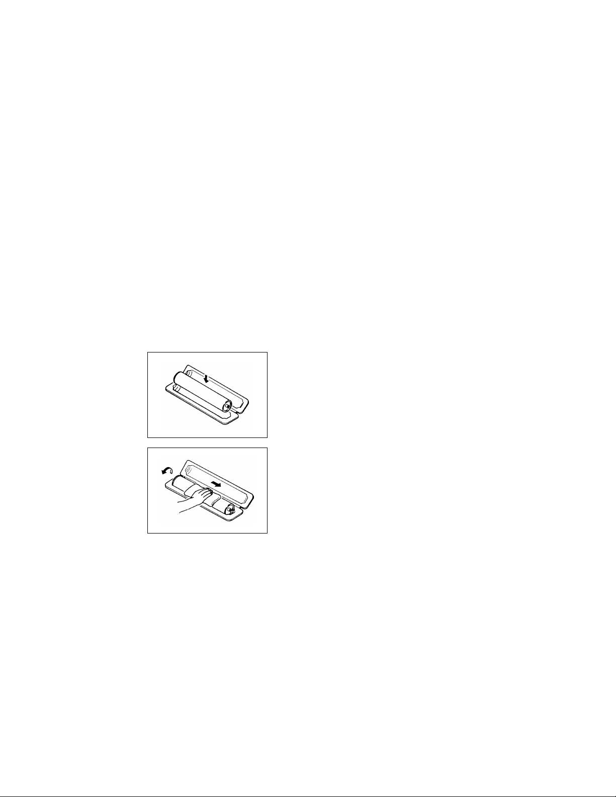
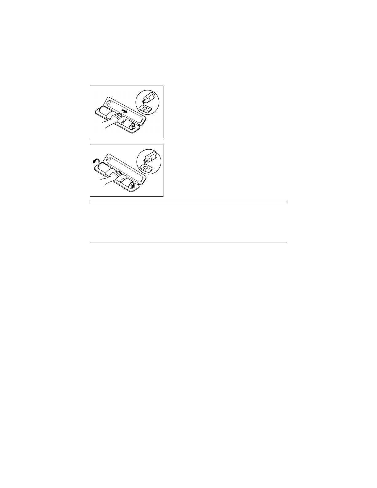
If, however, the surface is contaminated with fingerprints, clean it using the following proce-
dure.
A. Place the PC Drum into one half of its carton.
1076D001
1076D002
B. Gently wipe the residual toner off the surface of the
PC Drum with a dry, Dust-Free Cotton Pad.
• Turn the PC Drum so that the area of its surface on
which the line of toner left by the Cleaning Blade is
present is facing straight up. Wipe the surface in one
continuous movement from the rear edge of the PC
Drum to the front edge and off the surface of the PC
Drum.
• Turn the PC Drum slightly and wipe the newly
exposed surface area with a CLEAN face of the
Dust-Free Cotton Pad. Repeat this procedure until
the entire surface of the PC Drum has been thoroughly cleaned.
✽ At this time, always use a CLEAN face of the dry
Dust-Free Cotton Pad until no toner is evident on the
P-9
C. Soak a small amount of either ethyl alcohol or iso-
propyl alcohol into a clean, unused Dust-Free Cotton Pad which has been folded over into quarters.
Now, wipe the surface of the PC Drum in one continuous movement from its rear edge to its front
edge and off its surface one to two times.
✽ Never move the Pad back and forth.
1076D003
D. Using the SAME face of the Pad, repeat the proce-
dure explained in the latter half of step 3 until the
entire surface of the PC Drum has been wiped.
Always OVERLAP the areas when wiping. Two
complete turns of the PC Drum would be appropriate for cleaning.
1076D004
NOTES
• Even when the PC Drum is only locally dirtied, wipe the entire surface.
• Do not expose the PC Drum to direct sunlight. Clean it as quickly as possible even under
interior illumination.
• If dirt remains after cleaning, repeat the entire procedure from the beginning one more
time.
9. Handling of the Imaging Cartridge
✽ Only for Products Employing an Imaging Cartridge.
< During Transportation/Storage >
• The storage temperature is in the range between –20°C and +40°C.
• In summer, avoid leaving the Imaging Cartridge in a car for a long time.
< Handling >
• Store the Imaging Cartridge in a place that is not exposed to direct sunlight.
< Precautionary Information on the PC Drum Inside the Imaging Cartridge >
• Use care not to contaminate the surface of the PC Drum with oil-base solvent, fingerprints, and other foreign matter.
• Do not scratch the surface of the PC Drum.
• Do not attempt to wipe clean the surface of the PC Drum.
P-10

DIS/REASSEMBLY,
ADJUSTMENT

1. SAFETY INFORMATION
1-1. LASER SAFETY
• This i s a digit al machine certified as a class 1 laser product. There is no possibility of
danger f rom a laser, provided the mac hine is serv iced according to the instruction in this
manual.
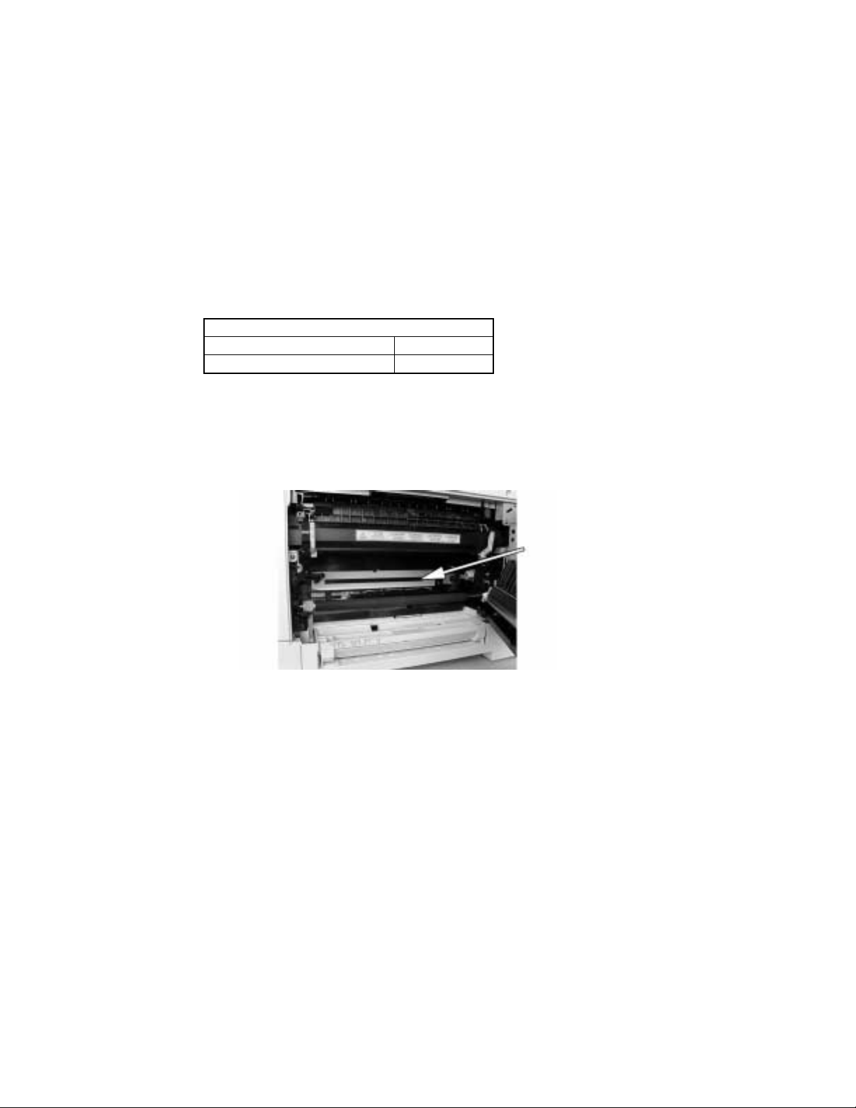
1-2. INTERNAL LASER RADIATION
Semiconductor laser
Maximu m aver age radiation pow er( * ) 26.4 µW
Wavelength 770-795 nm
*:Laser Ape rture of th e Pr i nt Hea d U ni t
• Thi s pr odu ct empl o y s a Cl as s 3 b l aser di ode t h at emits a n i n visi b l e l aser be am . The lase r
diode an d the s ca nn ing polygon mirr or are i nc or porated in the pr int head unit.
• The print head unit is NOT A FIELD SERVICE ITEM. Therefore, the print head unit
should not be opened under any circumstances.
Laser Aperture of
the Print Head Unit
This fig ur e Shows the view inside the Right Door
with the Im ag in g U ni t remove d.
D-1

the U.S.A., Canada
(CDRH Regulation)
• This machine is certified as a Class I Laser product under Radiation Performance Standard according to the Food, Drug and Cosmetic Act of 1990. Compliance is mandatory
for Laser products marketed in the United States and is reported to the Center for
Devices and Radiological Health (CDRH) of the U.S. Food and Drug Administration of
the U.S. Department of Health and Human Services (DHHS). This means that the device
does not produce hazardous laser radiation.
• The label shown to page D-4 indicates compliance with the CDRH regulations and must
be attached to laser products marketed in the United States.
CAUTION
Use of controls, adjustments or performance of procedures other than those specified in
this m anu al may result in hazardous radia tion exposure.
Semiconductor laser
Maximum power of the laser diode 5 mW
Wavelength 770-795 nm
All Areas
CAUTION
Use of controls, adjustments or performance of procedures other than those specified in
this m anu al may result in hazardous radia tion exposure.
Semiconductor laser
Maximum power of the laser diode 5 mW
Wavelength 770-795 nm
Denmark
ADVARSEL
Usynlig Laserstråling ved åbning, når sikkerhedsafbrydere er ude af funktion. Undgå
udsættelse for stråling. Klasse 1 laser produkt der opfylder IEC60825 sikkerheds kravene.
Halvlederlaser
Laserdiodens højeste styrke 5 mW
Bølgelængden 770-795 nm
D-2

Finland, Sweden
VARO!
Avattaessa ja suojalukitus ohitettaessa olet alttiina näkymättömälle lasersäteilylle. Älä
katso sä te es een.
LOUKAN 1 LASERLAITE
KLASS 1 LASER APPARAT
VAROITUS!
Laitteen Käyttäminen muulla kuin tässä käyttöohjeessa mainitulla tavalla saattaa altistaa
käyttä jä n turvallisuusl uo ka n 1 yl itt ä v äl le nä ky m ättömälle las ers äteilylle.
Puolijohdelaser
Laserd iodin suurin teho 5 mW
Aallonpituus 770-795 nm
VARNING!
Om apparaten används på annat sätt än i denna bruksanvisning specificerats, kan användaren ut sättas för osy nlig lase rstrålni ng, som överskri der gränse n för laserklass 1.
Halvledarlaser
Den maximala effekten för laserdioden 5 mW
Våglängden 770-795 nm
VARNING!
Osynlig laserstrålning när denna del är öppnad och spärren är urkopplad. Betrakta ej
strålen.
Norway
ADVERSEL
Derso m ap pa r ate t br ukes på annen måte e nn spesifisert i denne bruksanvisning, kan
brukeren utsettes for unsynlig laserstråling som overskrider grensen for laser klass 1.
Halvleder laser
Maksimal effekt till laserdiode 5 mW
Bølgelengde 770-795 nm
D-3
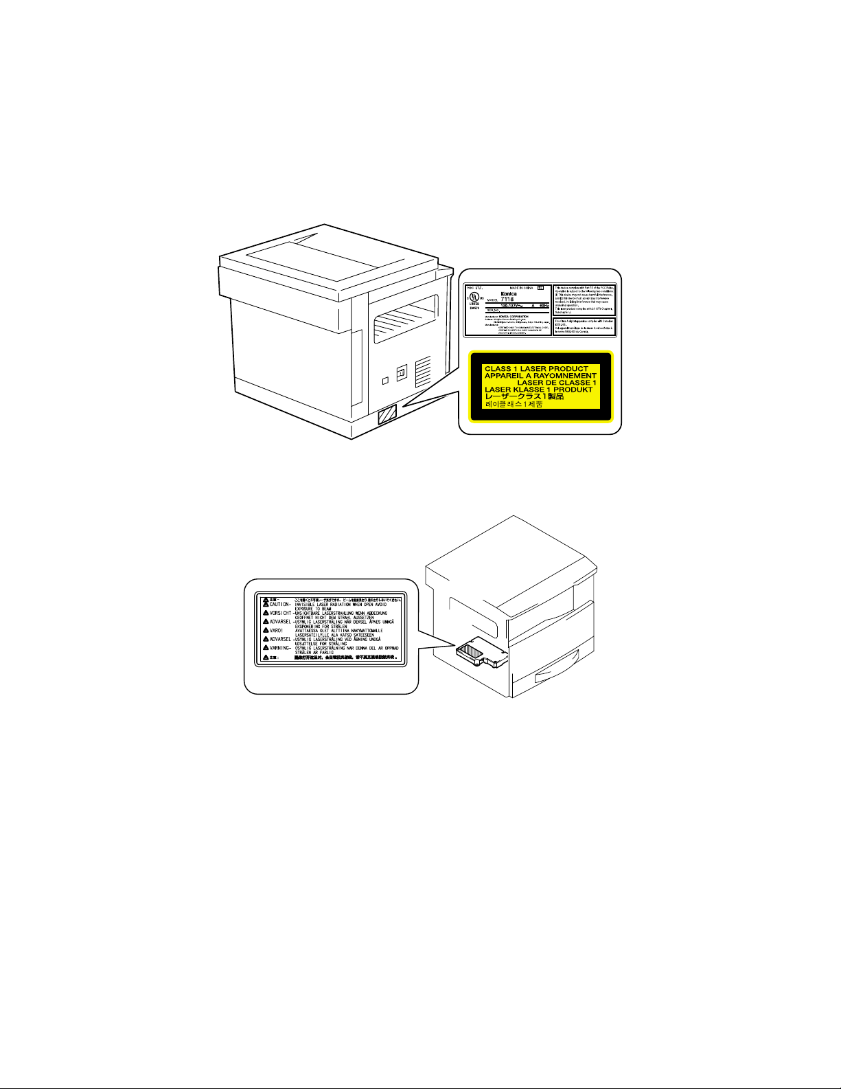
1-3. LASER SAFETY LABEL
• A laser safe ty la be ls i s attached to the out si de o f the machine as shown below.
Laser safety label
1-4. LASER CAUTION LABEL
• A laser caution label is attached to the inside of the machine as shown below.
4022D501AA
1-5. PRECAUTIONS FOR HANDLING THE LASER EQUIPMENT
• When l as er pro t e ctive goggles are t o be used, sele ct ones with a lens con f orming to the
above spec if ic ations.
• When a disassembly job needs to be performed in the laser beam path, such as when
working around the printerhead and PC Drum, be sure first to turn the copier OFF.
• If the job requires that the copier be l eft ON, t ake off your watch and ring and wear laser
protective goggles.
• A highly reflective tool can be dangerous if it is brought into the laser beam path. Use
utmost care when handling tools on the user’s premises.
D-4
2. SERVICE INSTR UCTIONS
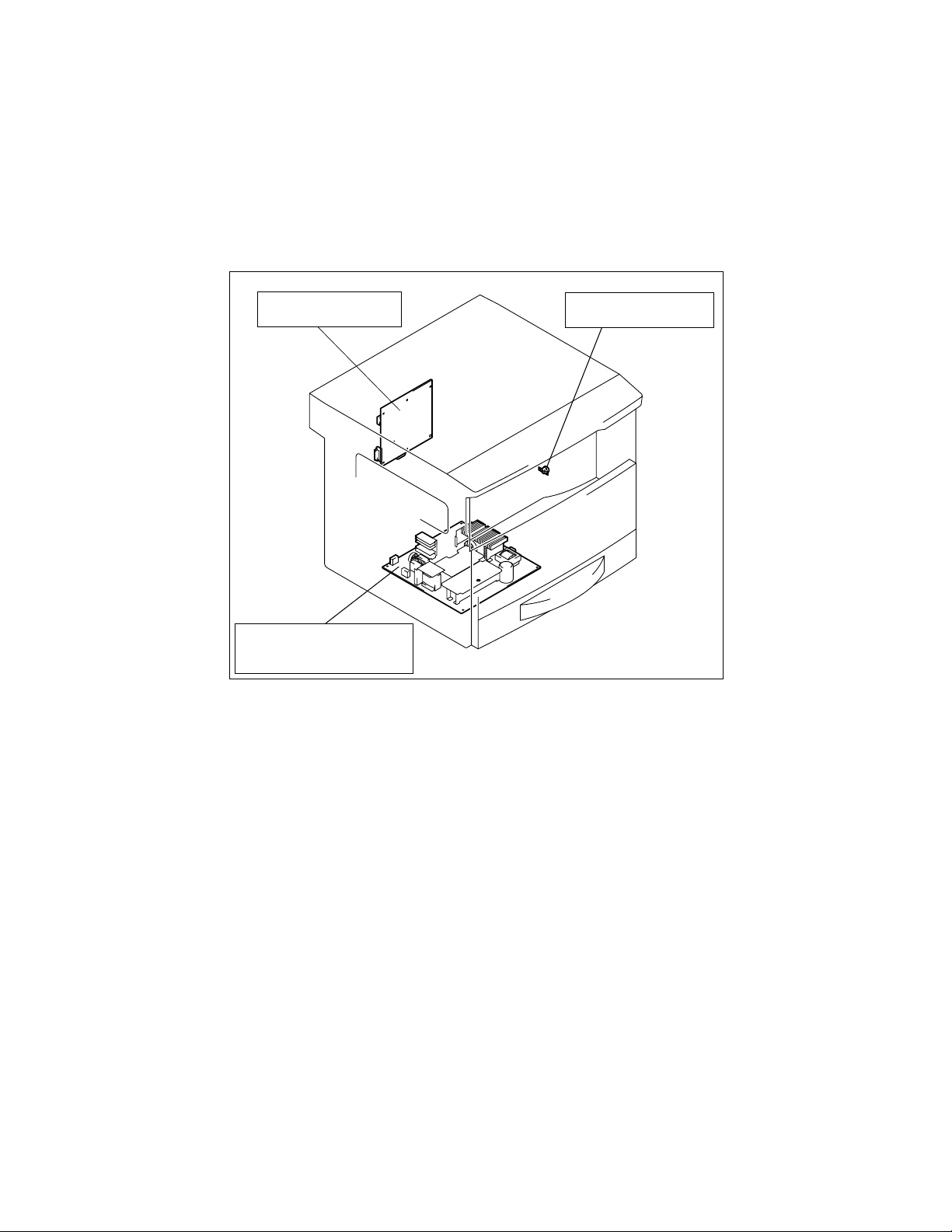
2-1. IDENTIFICATION OF FUSES AND CIRCUIT BREAKERS
Contr ol Board (P WB-C)
125 V 3 A
DC Power Supply (PU1)
100 V system 125 V 15 A (F2)
200 V system 250 V 6.3 A (F2)
Thermoswitch 1 (T S1)
250 V 7.5 A/1 25 V 15 A
4021D006AA
D-5
2-2. PARTS WHICH MUST NOT BE TOUCHED
(1) Red Painted Screws
Purpose of Application of Red Paint
Red pain t e d sc rew s sh ow th a t the as s embly or unit sec ur e d ca n on ly be adju sted or set at
the factory and shall not be readjusted, set, or removed in the field.
If it becomes unavoidably nece s sary to disas se mbl e any of th ese assemblies and units,
disassembly may be done provided that the conditions permitting reassembly are met.
Note also that when two or more screws are used on the part in question, only one representative screw may be marked with red paint.
(2) Variable Resistors on Board
Do not turn the variable resistors on boards for which no adjusting instructions are given in
“ADJUSTMENT.”
Other Screws not Marked with Red Paint
<PH Unit>
PH Unit
<IR Unit>
Left side face
PH Unit base plate
Right side face
D-6
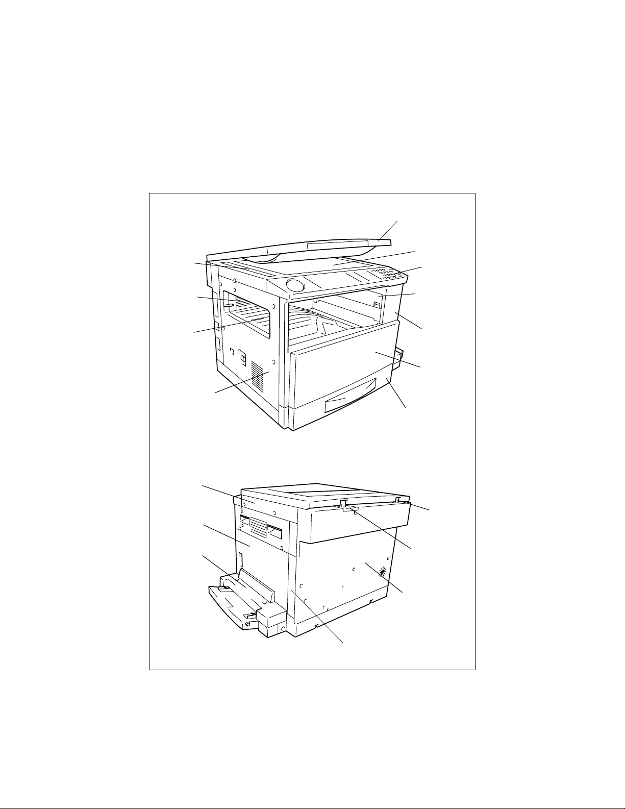
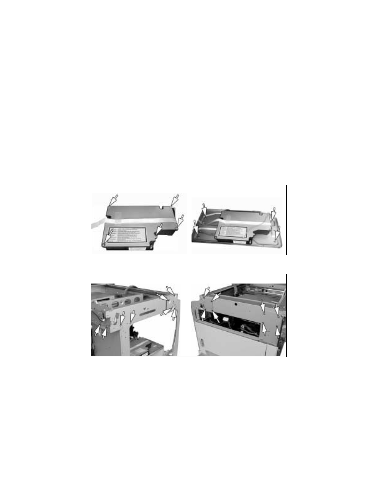
3. DISASSEMBLY/REASSEMBLY
3-1. DOORS, COVERS, AND EXTERIOR PARTS: IDENTIFICA TION
AND REMOVAL PROCEDURES
1
2
11
3
10
9
8
18
17
16
4
5
6
7
12
13
D-7
14
15

No. Part Name Removal Procedure
1 Ori gi nal Cover Pull the Original C over st raig ht up.
2 Original Glass
3 Control Panel
4 Right Inside Cover
5Front Cover
6Front Door
71st Tray
8 Left Cover
9 Upper Cover
10 Rear Inside Cover
11 ADF Glass Remove two ADF Glass mounting screws.
12 Left Hinge Remove no. 14. → Remove three Left Hinge mounting screws.
13 Right Hinge Remove no. 14. → Remove three Right Hinge mounting screws.
14 Rear Cover Remove six Rear Cover mounting screws.
15 Rear Right Cover
Multip le B y pass
16
Cover (when the
option is mounted)
17 Right Door
18 Right Cover
Remove no. 18. → Remove two holding brackets or no. 11 and
the Original Glass.
Remove two control panel mounting screws. → Remove two
ground wire mounting screws. → Remove one flat cable and
unplug one connecto r.
Remove no. 5. → Remove one Right Ins id e C over mounting
screw.
Remove no. 3. → Open the Front Do o r and r em ove si x Fron t
Cover mounting screws.
Open the Front Door and remove one band mounting screw. →
Snap off one C -c lip.
Slide out the 1st Tray. → Remove the fixing brackets on the right
and left.
Remove no. 3. → Remove no. 5. → Remove no. 14. → Remove
five Left Cov er mounting screws.
Remove no. 3. → Remove no. 5. → Remove no. 14. → Remove
no. 8. → Remove two scr ews an d t wo U p pe r Cove r mounting
screws.
Remove no. 3. → Remove no. 5. → Remove no. 14. → Remove
no. 8. → Remove no. 9. → Remove no. 4. → Remove two Rear
Inside C over mounting scre w s.
Remove no. 14. → Remove one Rear Right Cover mounting
screw.
Remove two Multiple Bypass Cover mounting screws.
Remove no. 14. → Remove no. 15. → Remove three Right Door
mounting screws .
Remove no. 3. → Remove no. 5. → Remove no. 14. → Remove
four Right Cover mounting screws.
D-8
 Loading...