

Konica Minolta 5450, 5440 DL, 5430 DL User Manual

SERVICE MANUAL
magicolor 5430 DL
magicolor 5430 DL
magicolor 5440 DL
magicolor 5440 DL
magicolor 5450
magicolor 5450
THEORY OF OPERATION
®
®
®
2005.042005.04
Ver. 3.0Ver. 3.0
SAFETY AND IMPORTANT WARNING ITEMS
SAFETY AND IMPORTANT WARNING ITEMS
Read carefully the Safety and Important Warning Items described below to understand
them before doing service work.
IMPORTANT NOTICE
Because of possible hazards to an inexperienced person servicing this product as well as
the risk of damage to the product, KONICA MINOLTA BUSINESS TECHNOLOGIES, INC.
(hereafter called the KMBT) strongly recommends that all servicing be performed only by
KMBT-trained service technicians.
Changes may have been made to this product to improve its performance after this Service
Manual was printed. Accordingly, KMBT does not warrant, either explicitly or implicitly, that
the information contained in this Service Manual is complete and accurate.
The user of this Service Manual must assume all risks of personal injury and/or damage to
the product while servicing the product for which this Service Manual is intended.
Therefore, this Service Manual must be carefully read before doing service work both in the
course of technical training and even after that, for performing maintenance and control of
the product properly.
Keep this Service Manual also for future service.
DESCRIPTION ITEMS FOR DANGER,
WARNING AND CAUTION
In this Service Manual, each of three expressions " DANGER", " WARNING", and
" CAUTION" is defined as follows together with a symbol mark to be used in a limited
meaning.
When servicing the product, the relevant works (disassembling, reassembling, adjustment,
repair, maintenance, etc.) need to be conducted with utmost care.
DANGER: Action having a high possibility of suffering death or serious injury
WARNING: Action having a possibility of suffering death or serious injury
CAUTION: Action having a possibility of suffering a slight wound, medium
trouble, and property damage
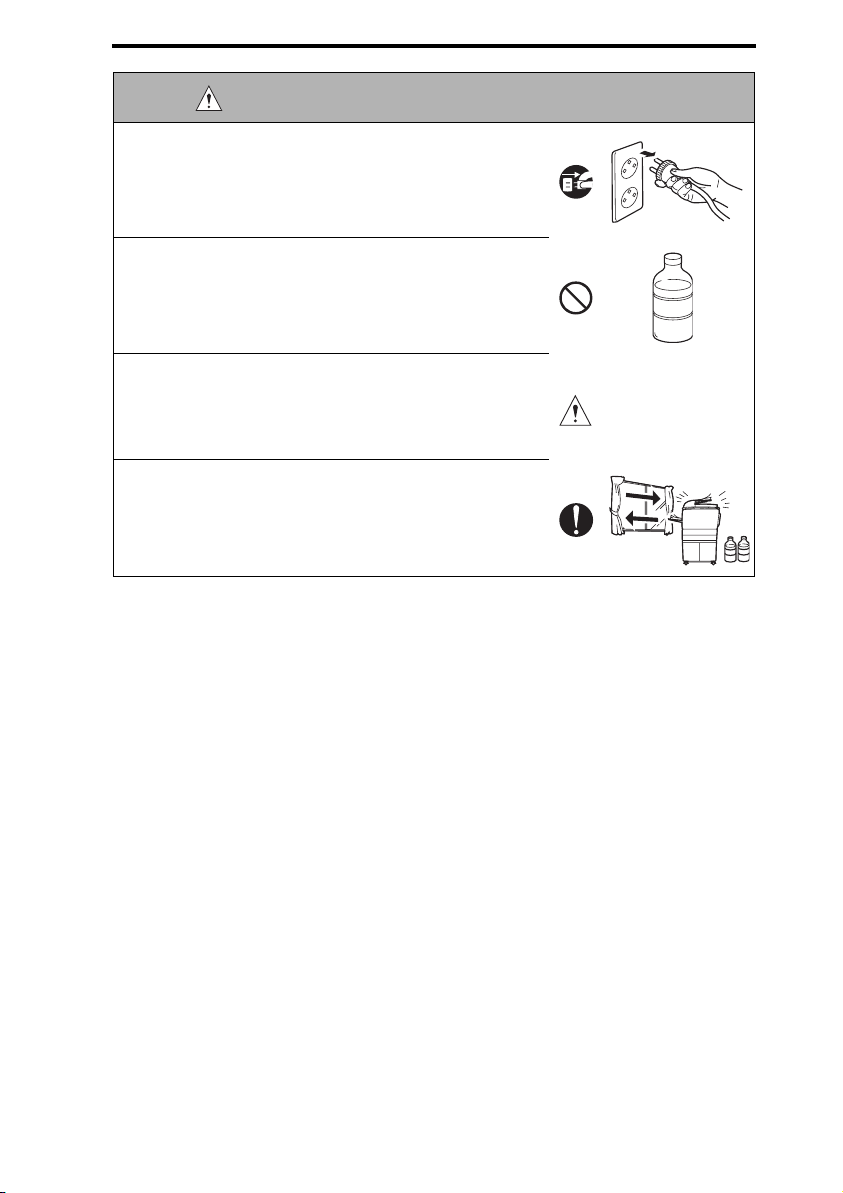
Symbols used for safety and important warning items are defined as follows:
:Precaution when servicing the
product.
:Prohibition when servicing the
product.
:Direction when servicing the
product.
General
precaution
General
prohibition
General
instruction
S-1
Electric hazard High temperature
Do not touch
with wet hand
Unplug Ground/Earth
Do not
disassemble
SAFETY AND IMPORTANT WARNING ITEMS
SAFETY WARNINGS
[1] MODIFICATIONS NOT AUTHORIZED BY KONICA MINOLTA
BUSINESS TECHNOLOGIES, INC.
KONICA MINOLTA brand products are renowned for their high reliability. This reliability is
achieved through high-quality design and a solid service network.
Product design is a highly complicated and delicate process where numerous mechanical,
physical, and electrical aspects have to be taken into consideration, with the aim of arriving
at proper tolerances and safety factors. For this reason, unauthorized modifications involve
a high risk of degradation in performance and safety. Such modifications are therefore
strictly prohibited. the points listed below are not exhaustive, but they illustrate the reasoning behind this policy.
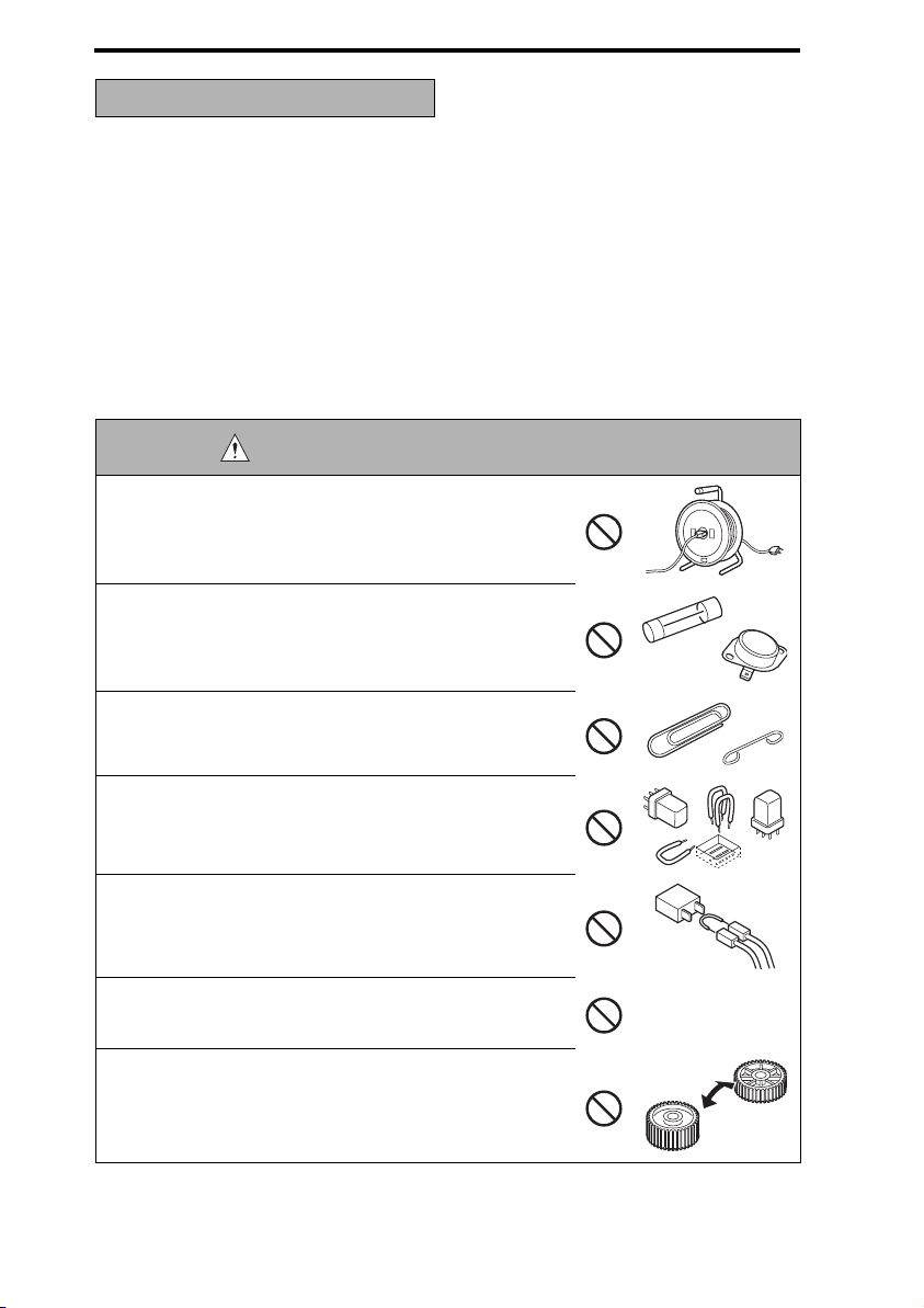
DANGER : PROHIBITED ACTIONS
• Using any cables or power cord not specified by KMBT.
• Using any fuse or thermostat not specified by KMBT.
Safety will not be assured, leading to a risk of fire and
injury.
• Disabling fuse functions or bridging fuse terminals with
wire, metal clips, solder or similar object.
• Disabling relay functions (such as wedging paper between
relay contacts)
• Disabling safety functions (interlocks, safety circuits, etc.)
Safety will not be assured, leading to a risk of fire and
injury.
• Making any modification to the product unless instructed
by KMBT
• Using parts not specified by KMBT
S-2
SAFETY AND IMPORTANT WARNING ITEMS
[2] CHECKPOINTS WHEN PERFORMING ON-SITE SERVICE
Konica Minolta brand products are extensively tested before shipping, to ensure that all
applicable safety standards are met, in order to protect the customer and customer engineer (hereafter called the CE) from the risk of injury. However, in daily use, any electrical
equipment may be subject to parts wear and eventual failure. In order to maintain safety
and reliability, the CE must perform regular safety checks.
1. Power Supply
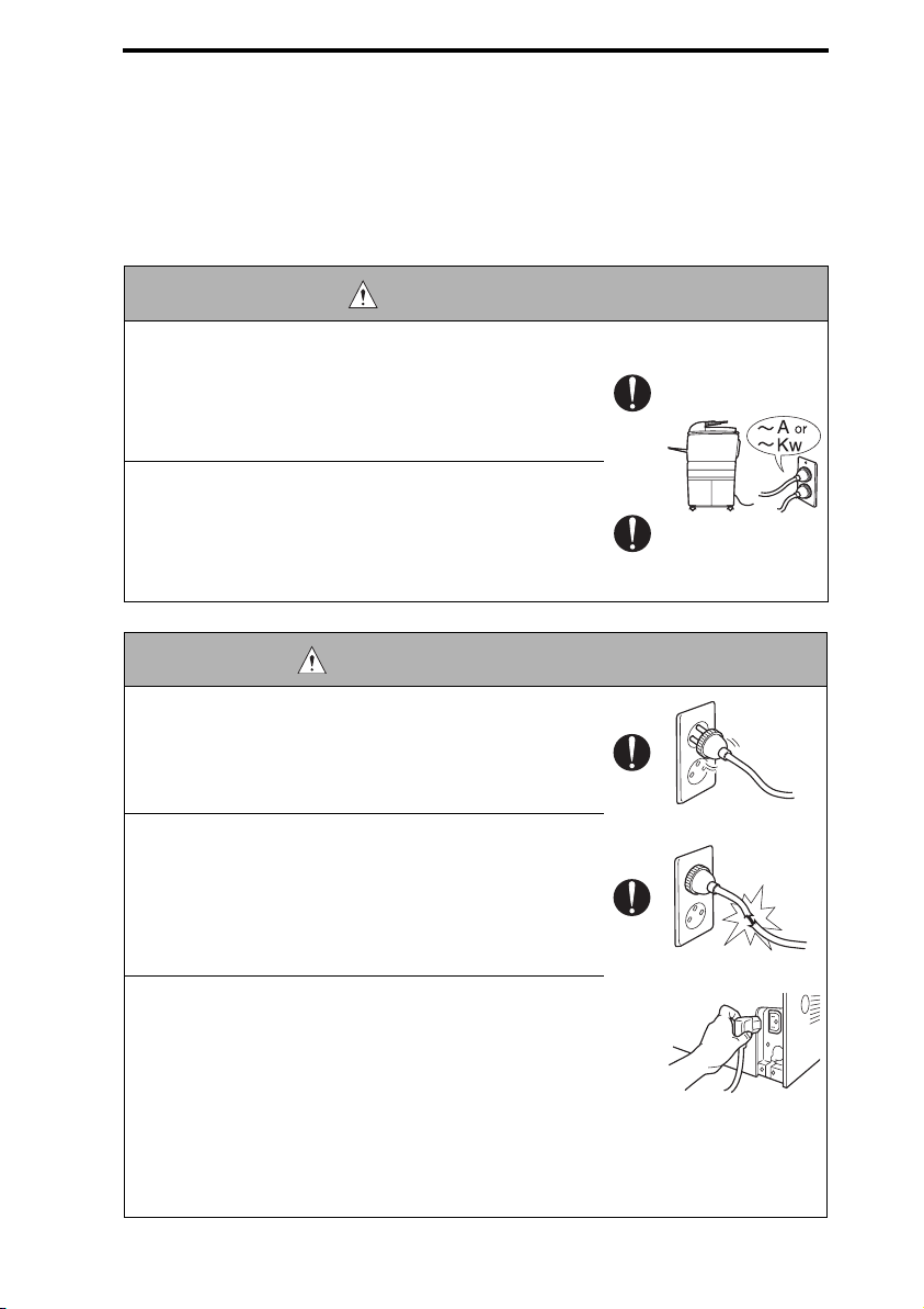
WARNING: Wall Outlet
• Check that mains voltage is as specified. Plug the power
cord into the dedicated wall outlet with a capacity greater
than the maximum power consumption.
If excessive current flows in the wall outlet, fire may
result.
• If two or more power cords can be plugged into the wall
outlet, the total load must not exceed the rating of the wall
outlet.
If excessive current flows in the wall outlet, fire may
result.
WARNING: Power Plug and Cord
• Make sure the power cord is plugged in the wall outlet
securely.
Contact problems may lead to increased resistance,
overheating, and the risk of fire.
• Check whether the power cord is damaged. Check
whether the sheath is damaged.
If the power plug, cord, or sheath is damaged, replace
with a new power cord (with plug and connector on each
end) specified by KMBT. Using the damaged power cord
may result in fire or electric shock.
• When using the power cord (inlet type) that came with this
product, be sure to observe the following precautions:
a. Make sure the connector is securely inserted in the inlet
on the left side panel of the product.
b. If the power cord or sheath is damaged, replace with a
new power cord (with plugs on both ends) specified by
KMBT.
If the power cord (inlet type) is not connected to the
product securely, a contact problem may lead to
increased resistance, overheating, and risk of fire.
S-3
SAFETY AND IMPORTANT WARNING ITEMS
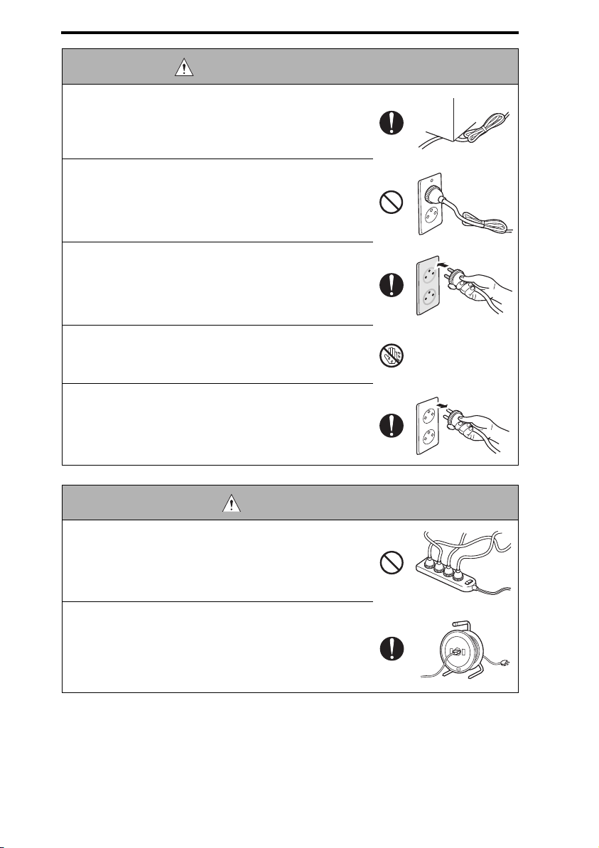
WARNING: Power Plug and Cord
• Check whether the power cord is not stepped on or
pinched by a table and so on.
Overheating may occur there, leading to a risk of fire.
• Do not bundle or tie the power cord.
Overheating may occur there, leading to a risk of fire.
• Check whether dust is collected around the power plug
and wall outlet.
Using the power plug and wall outlet without removing
dust may result in fire.
• Do not insert the power plug into the wall outlet with a wet
hand.
The risk of electric shock exists.
• When unplugging the power cord, grasp the plug, not the
cable.
The cable may be broken, leading to a risk of fire and
electric shock.
WARNING: Wiring
• Never use multi-plug adapters to plug multiple power cords
in the same outlet.
If used, the risk of fire exists.
• When an extension cord is required, use a specified one.
Current that can flow in the extension cord is limited, so
using a too long extension cord may result in fire.
Do not use an extension cable reel with the cable taken
up. Fire may result.
S-4
SAFETY AND IMPORTANT WARNING ITEMS
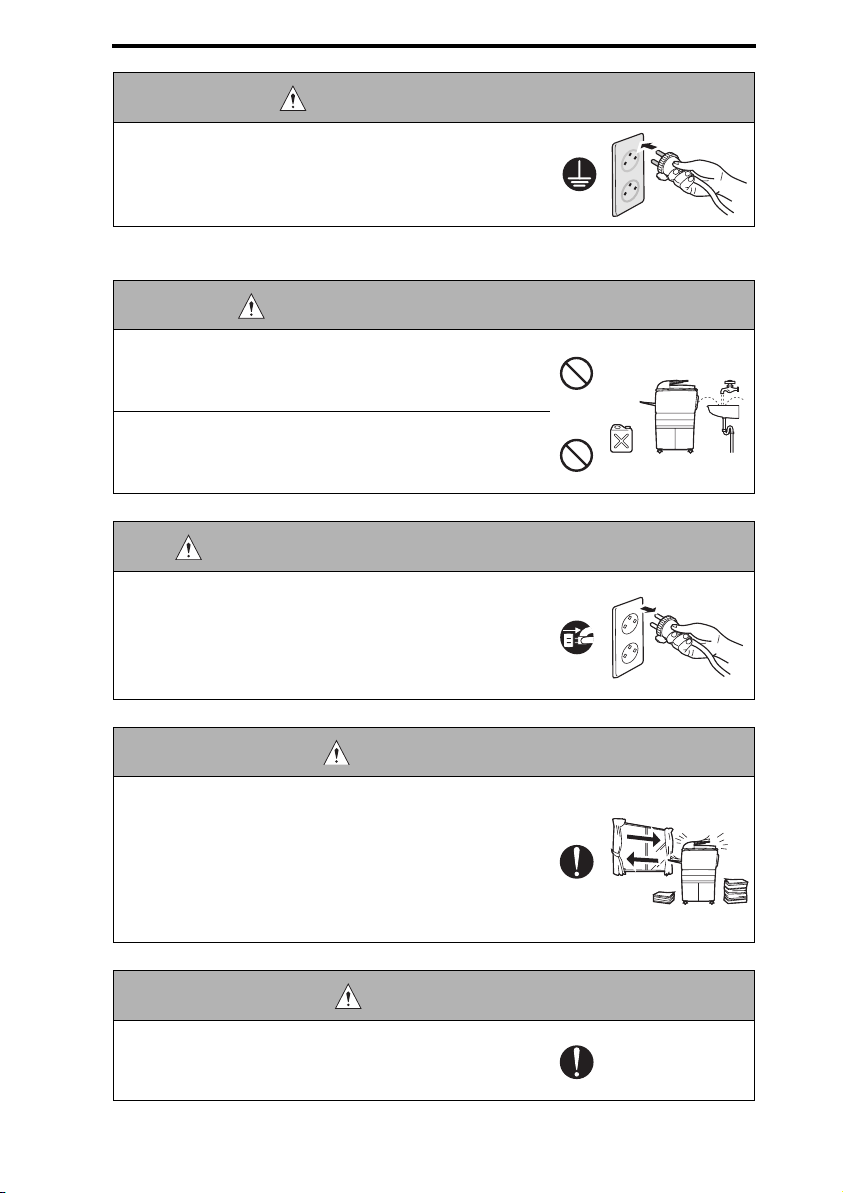
WARNING: Ground Connection
• Check whether the product is grounded properly.
If current leakage occurs in an ungrounded product, you
may suffer electric shock while operating the product.
Connect power plug to grounded wall outlet.
2. Installation Requirements
WARNING: Prohibited Installation Places
• Do not place the product near flammable materials or volatile materials that may catch fire.
A risk of fire exists.
• Do not place the product in a place exposed to water such
as rain.
A risk of fire and electric shock exists.
WARNING: When not Using the Product for a long time
• When the product is not used over an extended period of
time (holidays, etc.), switch it off and unplug the power
cord.
Dust collected around the power plug and outlet may
cause fire.
CAUTION: Ventilation
• The product generates ozone gas during operation, but it
will not be harmful to the human body.
If a bad smell of ozone is present in the following cases,
ventilate the room.
a. When the product is used in a poorly ventilated room
b. When taking a lot of copies
c. When using multiple products at the same time
CAUTION: Stability
• Be sure to lock the caster stoppers.
In the case of an earthquake and so on, the product may
slide, leading to a injury.
S-5
SAFETY AND IMPORTANT WARNING ITEMS
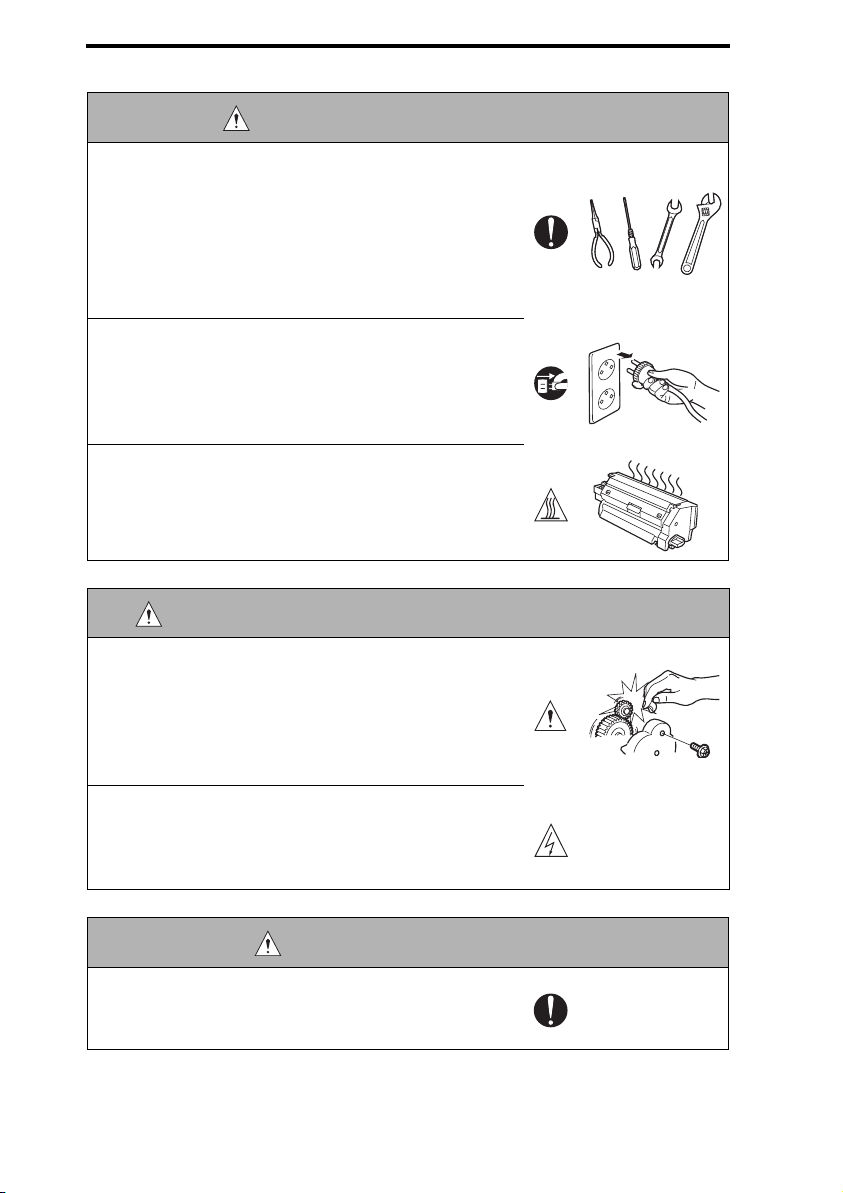
CAUTION: Inspection before Servicing
• Before conducting an inspection, read all relevant documentation (service manual, technical notices, etc.) and
proceed with the inspection following the prescribed procedure, using only the prescribed tools. Do not make any
adjustment not described in the documentation.
If the prescribed procedure or tool is not used, the product may break and a risk of injury or fire exists.
• Before conducting an inspection, be sure to disconnect
the power plugs from the product and options.
When the power plug is inserted in the wall outlet, some
units are still powered even if the POWER switch is
turned OFF. A risk of electric shock exists.
• The area around the fixing unit is hot.
You may get burnt.
WARNING: Work Performed with the Product Powered On
• Take every care when making adjustments or performing
an operation check with the product powered.
If you make adjustments or perform an operation check
with the external cover detached, you may touch live or
high-voltage parts or you may be caught in moving gears
or the timing belt, leading to a risk of injury.
• Take every care when servicing with the external cover
detached.
High-voltage exists around the drum unit. A risk of electric shock exists.
WARNING: Safety Checkpoints
• Check the exterior and frame for edges, burrs, and other
damages.
The user or CE may be injured.
S-6
SAFETY AND IMPORTANT WARNING ITEMS
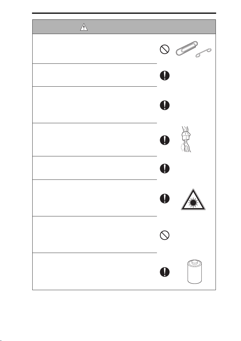
WARNING: Safety Checkpoints
• Do not allow any metal parts such as clips, staples, and
screws to fall into the product.
They can short internal circuits and cause electric shock
or fire.
• Check wiring for squeezing and any other damage.
Current can leak, leading to a risk of electric shock or
fire.
• Carefully remove all toner remnants and dust from electrical parts and electrode units such as a charging corona
unit.
Current can leak, leading to a risk of product trouble or
fire.
• Check high-voltage cables and sheaths for any damage.
Current can leak, leading to a risk of electric shock or
fire.
• Check electrode units such as a charging corona unit for
deterioration and sign of leakage.
Current can leak, leading to a risk of trouble or fire.
• Before disassembling or adjusting the write unit (P/H unit)
incorporating a laser, make sure that the power cord has
been disconnected.
The laser light can enter your eye, leading to a risk of
loss of eyesight.
• Do not remove the cover of the write unit. Do not supply
power with the write unit shifted from the specified mounting position.
The laser light can enter your eye, leading to a risk of
loss of eyesight.
• When replacing a lithium battery, replace it with a new lithium battery specified in the Parts Guide Manual. Dispose
of the used lithium battery using the method specified by
local authority.
Improper replacement can cause explosion.
S-7
SAFETY AND IMPORTANT WARNING ITEMS
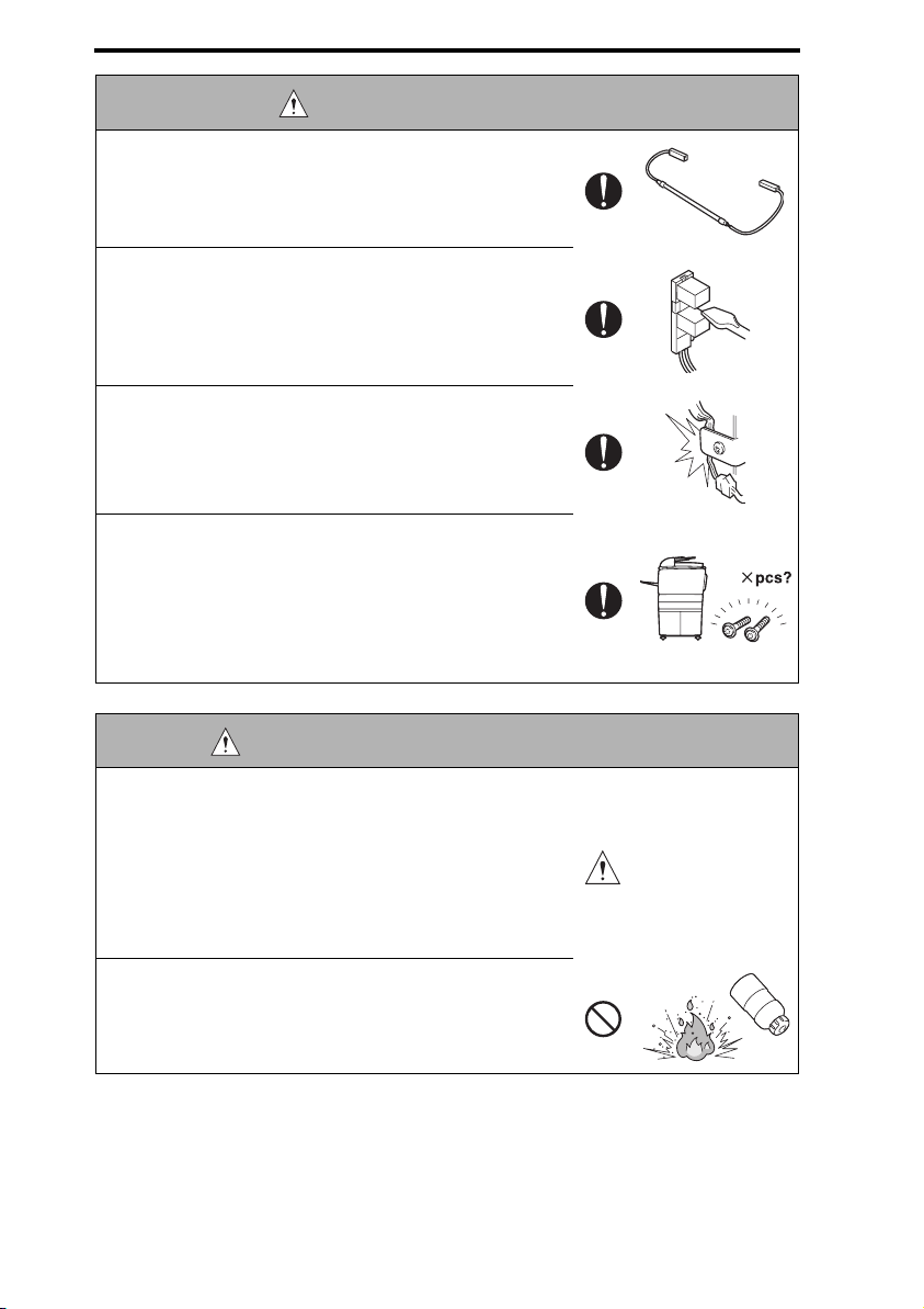
WARNING: Safety Checkpoints
• After replacing a part to which AC voltage is applied (e.g.,
optical lamp and fixing lamp), be sure to check the installation state.
A risk of fire exists.
• Check the interlock switch and actuator for loosening and
check whether the interlock functions properly.
If the interlock does not function, you may receive an
electric shock or be injured when you insert your hand in
the product (e.g., for clearing paper jam).
• Make sure the wiring cannot come into contact with sharp
edges, burrs, or other pointed parts.
Current can leak, leading to a risk of electric shock or
fire.
• Make sure that all screws, components, wiring, connectors, etc. that were removed for safety check and maintenance have been reinstalled in the original location. (Pay
special attention to forgotten connectors, pinched cables,
forgotten screws, etc.)
A risk of product trouble, electric shock, and fire exists.
WARNING: HANDLING OF CONSUMABLES
• Toner and developer are not harmful substances, but care
must be taken not to breathe excessive amounts or let the
substances come into contact with eyes, etc. It may be
stimulative.
If the substances get in the eye, rinse with plenty of water
immediately. When symptoms are noticeable, consult a
physician.
• Never throw the used cartridge and toner into fire.
You may be burned due to dust explosion.
S-8
SAFETY AND IMPORTANT WARNING ITEMS
CAUTION: HANDLING OF SERVICE MATERIALS
• Unplug the power cord from the wall outlet.
Drum cleaner (isopropyl alcohol) and roller cleaner (acetone-based) are highly flammable and must be handled
with care. A risk of fire exists.
• Do not replace the cover or turn the product ON before
any solvent remnants on the cleaned parts have fully
evaporated.
A risk of fire exists.
• Use only a small amount of cleaner at a time and take
care not to spill any liquid. If this happens, immediately
wipe it off.
A risk of fire exists.
• When using any solvent, ventilate the room well.
Breathing large quantities of organic solvents can lead to
discomfort.
S-9

SAFETY AND IMPORTANT WARNING ITEMS
[3] MEASURES TO TAKE IN CASE OF AN ACCIDENT
1. If an accident has occurred, the distributor who has been notified first must immediately take emergency measures to provide relief to affected persons and to prevent
further damage.
2. If a report of a serious accident has been received from a customer, an on-site evaluation must be carried out quickly and KMBT must be notified.
3. To determine the cause of the accident, conditions and materials must be recorded
through direct on-site checks, in accordance with instructions issued by KMBT.
[4] CONCLUSION
1. Safety of users and customer engineers depends highly on accurate maintenance and
administration. Therefore, safety can be maintained by the appropriate daily service
work conducted by the customer engineer.
2. When performing service, each product on the site must be tested for safety. The customer engineer must verify the safety of parts and ensure appropriate management of
the equipment.
S-10
SAFETY AND IMPORTANT WARNING ITEMS
[5] Laser Safety
• This is a digital machine certified as a class 1 laser product. There is no possibility of
danger from a laser, provided the machine is serviced according to the instruction in this
manual.
5.1 Internal Laser Radiation
semiconductor laser
Maximum power of the laser diode 15 mW
Maximum average radiation power (*) 7.2 µW
Wavelength 770-800 nm
*:at laser aperture of the Print Head Unit
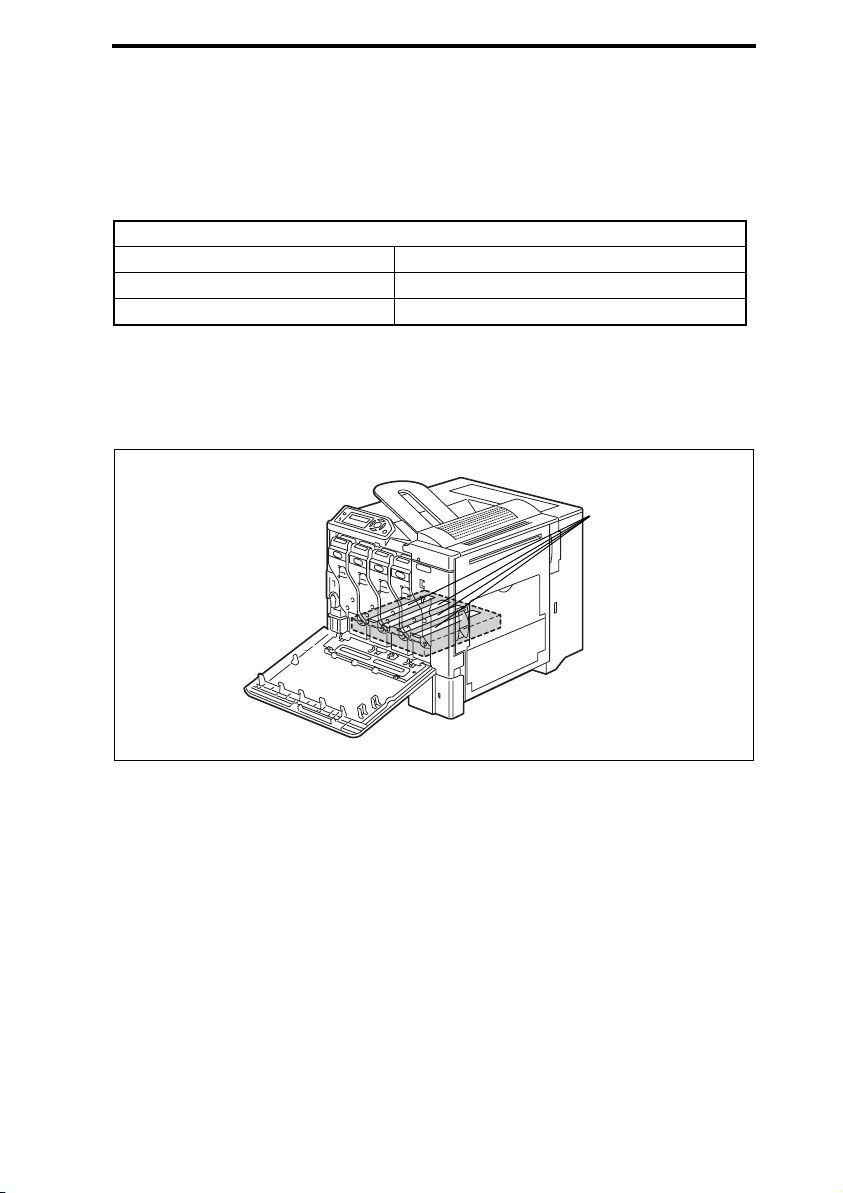
• This product employs a Class 3b laser diode that emits an invisible laser beam. The laser
diode and the scanning polygon mirror are incorporated in the print head unit.
• The print head unit is NOT A FIELD SERVICEABLE ITEM. Therefore, the print head unit
should not be opened under any circumstances.
Laser Aperture of
the Print Head Unit
This figure shows the view
inside the Front Door.
S-11
4138safe002c0

SAFETY AND IMPORTANT WARNING ITEMS
the U.S.A., Canada
(CDRH Regulation)
• This machine is certified as a Class I Laser product under Radiation Performance Standard according to the Food, Drug and Cosmetic Act of 1990. Compliance is mandatory
for Laser products marketed in the United States and is reported to the Center for
Devices and Radiological Health (CDRH) of the U.S. Food and Drug Administration of
the U.S. Department of Health and Human Services (DHHS). This means that the device
does not produce hazardous laser radiation.
• The label shown to page 14 indicates compliance with the CDRH regulations and must
be attached to laser products marketed in the United States.
.
CAUTION
• Use of controls, adjustments or performance of procedures other than those
specified in this manual may result in hazardous radiation exposure.
semiconductor laser
Maximum power of the laser diode 15 mW
Wavelength 770-800 nm
All Areas
CAUTION
• Use of controls, adjustments or performance of procedures other than those
specified in this manual may result in hazardous radiation exposure.
semiconductor laser
Maximum power of the laser diode 15 mW
Wavelength 770-800 nm
Denmark
ADVARSEL
• Usynlig laserstråling ved åbning, når sikkerhedsafbrydere er ude af funktion.
Undgå udsættelse for stråling. Klasse 1 laser produkt der opfylder IEC60825-1
sikkerheds kravene.
halvlederlaser
Laserdiodens højeste styrke 15 mW
bølgelængden 770-800 nm
S-12

SAFETY AND IMPORTANT WARNING ITEMS
Finland, Sweden
LUOKAN 1 LASERLAITE
KLASS 1 LASER APPARAT
VAR OITUS!
• Laitteen käyttäminen muulla kuin tässä käyttöohjeessa mainitulla tavalla saattaa altistaa käyttäjän turvallisuusluokan 1 ylittävälle näkymättömälle lasersäteilylle.
puolijohdelaser
Laserdiodin suurin teho 15 mW
aallonpituus 770-800 nm
VARNING!
• Om apparaten används på annat sätt än i denna bruksanvisning specificerats,
kan användaren utsättas för osynlig laserstrålning, som överskrider gränsen
för laserklass 1.
halvledarlaser
Den maximala effekten för laserdioden 15 mW
våglängden 770-800 nm
VAR O!
• Avattaessa ja suojalukitus ohitettaessa olet alttiina näkymättomälle lasersäteilylle. Älä katso säteeseen.
VARNING!
• Osynlig laserstråining när denna del är öppnad och spärren är urkopplad.
Betrakta ej stråien.
Norway
ADVERSEL
• Dersom apparatet brukes på annen måte enn spesifisert i denne bruksanvisning, kan brukeren utsettes för unsynlig laserstrålning, som overskrider grensen
for laser klass 1.
halvleder laser
Maksimal effekt till laserdiode 15 mW
bølgelengde 770-800 nm
S-13
SAFETY AND IMPORTANT WARNING ITEMS
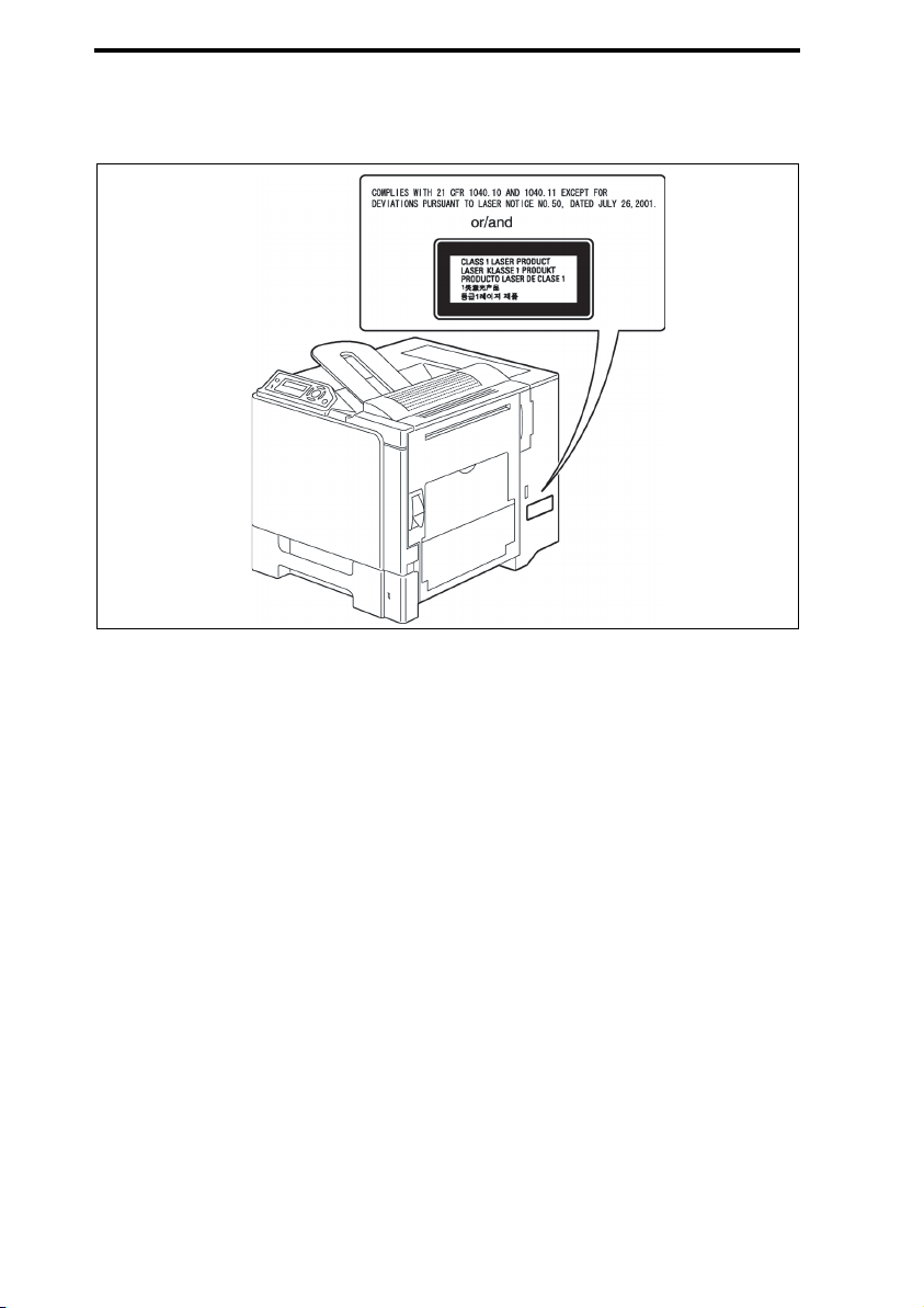
5.2 Laser Safety Label
• A laser safety label is attached to the the machine as shown below.
4138safe004c0
S-14
SAFETY AND IMPORTANT WARNING ITEMS
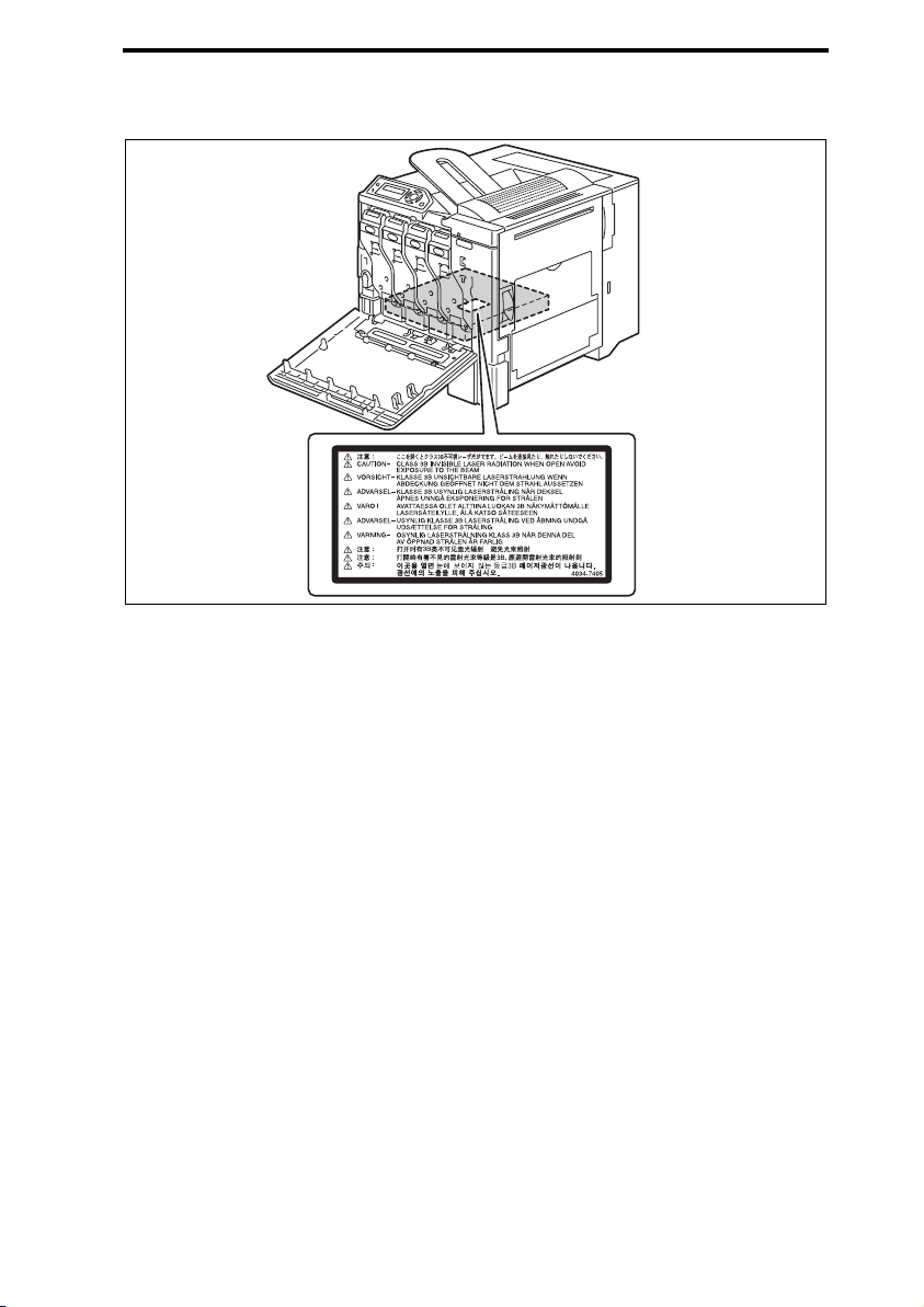
5.3 Laser Caution Label
• A laser caution label is attached to the inside of the machine as shown below.
4138safe001c0
5.4 PRECAUTIONS FOR HANDLING THE LASER EQUIPMENT
• When laser protective goggles are to be used, select ones with a lens conforming to the
above specifications.
• When a disassembly job needs to be performed in the laser beam path, such as when
working around the printerhead and PC Drum, be sure first to turn the printer OFF.
• If the job requires that the printer be left ON, take off your watch and ring and wear laser
protective goggles.
• A highly reflective tool can be dangerous if it is brought into the laser beam path. Use
utmost care when handling tools on the user’s premises.
• The Print Head are not to be disassembled or adjusted in the field. Replace the Unit or
Assembly including the Control Board. Therefore, remove the Laser Diode, and do not
perform Control Board trimmer adjustment.
S-15
SAFETY AND IMPORTANT WARNING ITEMS
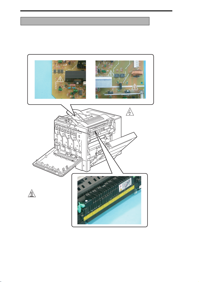
WARNING INDICATIONS ON THE MACHINE
Caution labels shown are attached in some areas on/in the machine.
When accessing these areas for maintenance, repair, or adjustment, special care should
be taken to avoid burns and electric shock.
High voltage
High temperature
4138fsS001c0
S-16
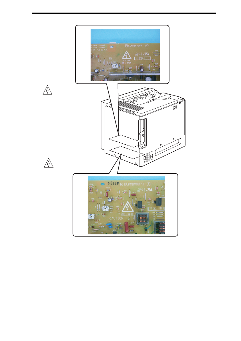
High voltage
High voltage
SAFETY AND IMPORTANT WARNING ITEMS
S-17
4138fsS002c0

SAFETY AND IMPORTANT WARNING ITEMS
S-18

SERVICE MANUAL
®
THEORY OF OPERATION
magicolor 5430 DL
®
magicolor 5440 DL
®
magicolor 5450
Main Unit
2005.04
Ver. 3.0


magicolor 5430 DL /5440 DL /5450 Theory of Operation
CONTENTS
I Outline
1. System configuration............................................................................................ 1-1
2. Product specifications ..........................................................................................1-2
2.1 Type ................................................................................................................... 1-2
2.2 Functions ........................................................................................................... 1-3
2.3 Maintenance ...................................................................................................... 1-5
2.4 Machine Specifications...................................................................................... 1-5
2.5 Operating Environment...................................................................................... 1-5
3. Center cross section ............................................................................................ 1-6
4. Paper path............................................................................................................1-7
5. Image creation process........................................................................................ 1-8
II Composition/Operation
1. Overall composition.............................................................................................. 2-1
1.1 Timing chart at machine powerup ..................................................................... 2-1
1.2 Control block diagram........................................................................................ 2-2
2. Print head (PH) .................................................................................................... 2-3
2.1 Composition....................................................................................................... 2-3
2.2 Operation ...........................................................................................................2-4
2.2.1 Overview....................................................................................................... 2-4
2.2.2 Laser exposure process ...............................................................................2-4
2.2.3 Laser emission timing ................................................................................... 2-5
2.2.4 Laser emission area .....................................................................................2-5
2.2.5 Laser light intensity control ........................................................................... 2-6
2.2.6 Registration correction control ...................................................................... 2-6
3. Toner Cartridge (TC) / TC Overall composition ....................................................2-7
3.1 Composition....................................................................................................... 2-7
3.2 Drive ................................................................................................................2-10
3.3 Operation ......................................................................................................... 2-12
3.3.1 Configuration of Toner Cartridge ................................................................ 2-12
3.3.2 Loading/unloading mechanism of Toner Cartridge..................................... 2-12
3.3.3 Toner Cartridge life control ......................................................................... 2-13
4. Toner Cartridge / Hopper ................................................................................... 2-14
4.1 Composition..................................................................................................... 2-14
4.2 Operation ......................................................................................................... 2-15
4.2.1 Toner Level Detection (magicolor 5430DL/5440DL)................................... 2-15
4.2.2 Toner Level Detection (magicolor 5450) ..................................................... 2-15
I Outline
II Composition/Operation
i

I Outline
II Composition/Operation
magicolor 5430 DL /5440 DL Theory of Operation
4.2.3 Toner near-empty condition detection ........................................................ 2-15
4.2.4 Toner empty condition detection................................................................. 2-17
4.2.5 Toner replenishing mechanism/control ....................................................... 2-19
5. Toner Cartridge / Photo Conductor .................................................................... 2-22
5.1 Composition .................................................................................................... 2-22
5.2 Operation......................................................................................................... 2-22
5.2.1 Photo Conductor drive mechanism ............................................................ 2-22
5.2.2 Photo Conductor post-exposure control..................................................... 2-23
5.2.3 Photo Conductor total exposure control upon recovery ............................. 2-23
5.2.4 Photo Conductor small amount rotation control ......................................... 2-24
6. Toner Cartridge / Charge corona section ........................................................... 2-25
6.1 Composition .................................................................................................... 2-25
6.2 Operation......................................................................................................... 2-26
6.2.1 Charge Corona Unit ON/OFF control ......................................................... 2-26
6.2.2 Output during pre-process ......................................................................... 2-26
6.2.3 Output during post-process ........................................................................ 2-26
6.2.4 Ozone ventilation mechanism .................................................................... 2-27
7. Toner Cartridge / Developing Unit ...................................................................... 2-28
7.1 Composition .................................................................................................... 2-28
7.2 Operation......................................................................................................... 2-30
7.2.1 Developing drive control ............................................................................. 2-30
7.2.2 Toner flow ................................................................................................... 2-31
7.2.3 Developing system ..................................................................................... 2-32
7.2.4 Developing bias Vpp control (Ds compensation control)............................ 2-33
7.2.5 Developing bias duty control (compensation control of the maximum
amount of toner sticking to the Transfer Belt)............................................ 2-34
7.2.6 Gamma correction control .......................................................................... 2-35
7.2.7 Cleaning mechanism.................................................................................. 2-36
8. 1st transfer section............................................................................................. 2-37
8.1 Composition .................................................................................................... 2-37
8.2 Drive ................................................................................................................ 2-39
8.3 Operation......................................................................................................... 2-40
8.3.1 Transfer Belt speed control......................................................................... 2-40
8.3.2 1st transfer output control........................................................................... 2-40
8.3.3 1st Transfer Roller pressure/retraction control............................................ 2-41
8.3.4 1st Transfer Roller pressure/retraction failure detection control ................. 2-44
8.3.5 Transfer Belt cleaning................................................................................. 2-45
8.3.6 Toner Collecting Port Shutter mechanism .................................................. 2-46
9. 2nd transfer section............................................................................................ 2-47
ii

magicolor 5430 DL /5440 DL /5450 Theory of Operation
9.1 Composition..................................................................................................... 2-47
9.1.1 Drive ...........................................................................................................2-48
9.2 Operation ......................................................................................................... 2-49
9.2.1 2nd Transfer Roller pressure mechanism ................................................... 2-49
9.2.2 2nd Transfer Roller pressure position deviation preventive mechanism ..... 2-51
9.2.3 2nd transfer voltage control ........................................................................2-51
9.2.4 2nd transfer voltage setting control (ATVC: Auto Transfer Voltage
Control)...................................................................................................... 2-52
9.2.5 2nd transfer voltage fine-adjustment control............................................... 2-53
9.2.6 2nd Transfer Roller pressure/retraction failure detection control ................2-53
9.2.7 2nd Transfer Roller cleaning control ........................................................... 2-53
9.2.8 2nd Transfer Roller cleaning operation timing ............................................2-54
10. Toner collecting section...................................................................................... 2-55
10.1 Composition..................................................................................................... 2-55
10.2 Drive ................................................................................................................2-56
10.3 Operation ......................................................................................................... 2-57
10.3.1 Toner collecting mechanism ....................................................................... 2-57
10.3.2 Toner Collecting Port Shutter mechanism .................................................. 2-57
10.3.3 Waste Toner Box locking mechanism ......................................................... 2-58
10.3.4 Waste Toner Box locked position detection mechanism............................. 2-58
10.3.5 Waste Toner Box-in-position detection mechanism ....................................2-58
10.3.6 Waste toner near-full condition detection ................................................... 2-59
10.3.7 Waste toner full condition detection control................................................ 2-61
11. AIDC Sensor ......................................................................................................2-63
11.1 Composition..................................................................................................... 2-63
11.1.1 Drive ........................................................................................................... 2-64
11.2 Operation ......................................................................................................... 2-64
11.2.1 Toner density detection control................................................................... 2-64
11.2.2 AIDC Sensor calibration control .................................................................2-65
11.2.3 AIDC Sensor shutter mechanism ...............................................................2-66
12. Paper feed section (magicolor 5430 DL)............................................................ 2-67
12.1 Composition..................................................................................................... 2-67
12.2 Drive ................................................................................................................2-68
12.3 Operation ......................................................................................................... 2-69
12.3.1 Paper Lift Plate mechanism........................................................................ 2-69
12.3.2 Paper separation mechanism..................................................................... 2-69
12.3.3 Paper feed control ...................................................................................... 2-70
12.3.4 Paper supply level detection control ........................................................... 2-70
12.3.5 Paper empty condition detection control.....................................................2-71
I Outline
II Composition/Operation
iii

I Outline
II Composition/Operation
magicolor 5430 DL /5440 DL Theory of Operation
12.3.6 Edge Guide Plate ....................................................................................... 2-71
12.3.7 Trailing Edge Guide Plate........................................................................... 2-71
12.3.8 Paper size detection control ....................................................................... 2-72
12.3.9 Paper misfeed detection control................................................................. 2-72
13. Paper feed section (magicolor 5440DL/5450).................................................... 2-73
13.1 Composition .................................................................................................... 2-73
13.2 Drive ................................................................................................................ 2-74
13.3 Operation......................................................................................................... 2-74
13.3.1 Paper Lift Plate mechanism ....................................................................... 2-74
13.3.2 Paper separation mechanism..................................................................... 2-75
13.3.3 Paper feed control ...................................................................................... 2-75
13.3.4 Paper supply level detection control ........................................................... 2-76
13.3.5 Paper empty condition detection control .................................................... 2-76
13.3.6 Edge Guide Plate ....................................................................................... 2-77
13.3.7 Trailing Edge Guide Plate........................................................................... 2-77
13.3.8 Tray detection control ................................................................................. 2-78
13.3.9 Paper misfeed detection control................................................................. 2-78
14. Manual feed section (magicolor 5440DL/5450) ................................................. 2-79
14.1 Composition .................................................................................................... 2-79
14.2 Drive ................................................................................................................ 2-80
14.3 Operation......................................................................................................... 2-81
14.3.1 Paper Lift Plate mechanism ....................................................................... 2-81
14.3.2 Paper separation mechanism..................................................................... 2-82
14.3.3 Paper feed control ...................................................................................... 2-82
14.3.4 Paper empty condition detection control .................................................... 2-83
14.3.5 Edge Guide Plate ....................................................................................... 2-83
14.3.6 Paper misfeed detection control................................................................. 2-84
15. Conveyance section........................................................................................... 2-85
15.1 Composition .................................................................................................... 2-85
15.2 Drive ................................................................................................................ 2-86
15.3 Operation......................................................................................................... 2-87
15.3.1 Conveyance speed control ......................................................................... 2-87
15.3.2 Synchronizing Roller control....................................................................... 2-87
15.3.3 Control of loop formed before Synchronizing Roller................................... 2-88
15.3.4 Control of loop formed before 2nd transfer................................................. 2-89
15.3.5 Control of loop formed before fusing section.............................................. 2-90
15.3.6 Paper neutralization.................................................................................... 2-91
15.3.7 OHP film detection control.......................................................................... 2-91
iv

magicolor 5430 DL /5440 DL /5450 Theory of Operation
15.3.8 Size error detection control......................................................................... 2-92
15.3.9 Conveyance system paper misfeed detection control ................................2-93
15.3.10 Control of detection of paper left in conveyance system ............................2-94
15.3.11 Control of detection of paper left in machine upon stoppage of paper
conveyance................................................................................................ 2-95
15.3.12 Temperature/humidity Sensor..................................................................... 2-95
16. Fusing section .................................................................................................... 2-96
16.1 Composition..................................................................................................... 2-96
16.2 Drive ................................................................................................................2-98
16.3 Operation ......................................................................................................... 2-99
16.3.1 Fusing Pressure Roller pressure selection mechanism .............................2-99
16.3.2 Fusing Pressure Roller drive control ..........................................................2-99
16.3.3 Fusing temperature control....................................................................... 2-104
16.3.4 Fusing temperature control management................................................. 2-105
16.3.5 Warm-up control ....................................................................................... 2-106
16.3.6 Post-warm-up control................................................................................ 2-108
16.3.7 Wait control............................................................................................... 2-108
16.3.8 Print control ..............................................................................................2-109
16.3.9 Post-print control.......................................................................................2-110
16.3.10 Heater OFF control................................................................................... 2-110
16.3.11 Heater control........................................................................................... 2-111
16.3.12 PPM control.............................................................................................. 2-111
16.4 Malfunction detection..................................................................................... 2-112
16.4.1 Fusing Unit malfunctions ..........................................................................2-112
16.4.2 Fusing Motor abnormal rotation detection control ....................................2-112
16.4.3 Warm-up failure detection control............................................................. 2-113
16.4.4 Abnormally low temperature detection control .........................................2-113
16.4.5 Abnormally high temperature detection control ........................................2-114
16.4.6 Open-circuited Heating Roller Thermistor
(incorrect installation) detection control ...................................................2-114
16.4.7 Open-circuited Fusing Pressure Roller Thermistor
(incorrect installation) detection control ...................................................2-115
16.4.8 Abnormal temperature increase rate detection control............................. 2-115
16.4.9 Protection against abnormally high temperature ...................................... 2-116
17. Image stabilization control................................................................................ 2-118
17.1 Overview of image stabilization control .........................................................2-118
17.1.1 Complete correction control...................................................................... 2-118
17.1.2 Simplified correction control .....................................................................2-119
17.1.3 Image stabilization control execution request........................................... 2-120
I Outline
II Composition/Operation
v

I Outline
II Composition/Operation
magicolor 5430 DL /5440 DL Theory of Operation
17.1.4 Conditions enabling execution of stabilization control at the end of
a print cycle of given conditions .............................................................. 2-120
17.1.5 Combination and execution sequence of different sub-controls ............... 2-121
17.2 Operation flow of image stabilization control upon replacement of unit ........ 2-122
18. Miscellaneous .................................................................................................. 2-123
18.1 Fan control..................................................................................................... 2-123
18.1.1 Composition ............................................................................................. 2-123
18.1.2 Control...................................................................................................... 2-124
vi
Main Unit Theory of Operation System Configuration
I Outline
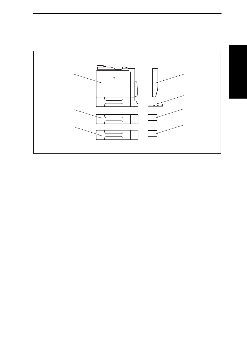
1. System Configuration
System Front View
[7]
[6]
[5]
[1] Duplex Option [5] Optional Lower Feeder Unit
[2] Optional DIMM [6] Optional Lower Feeder Unit
Optional Camera Direct Photo Print Card
[3]
(magicolor 5440 DL only)
Optional Hard Disk Drive (HDD)
[4]
(magicolor 5450 only)
[7] Main Unit
[1]
[2]
[3]
[4]
I Outline
4138fs1501c4
1-1

Product Specifications Main Unit Theory of Operation
2. Product Specifications
2.1 Type
Type Desktop tandem full-color laser beam printer
Printing System Semiconductor laser and electrostatic image transfer to plain paper
Exposure System 4 laser diode and polygon mirror
PC Drum Type OPC (organic photo conductor)
Photoconductor
I Outline
Cleaning
Print Density
Paper Feeding
System
Developing System Single-element developing system
Charging System DC comb electrode Scorotron system
Image Transfer
System
Paper Separating
System
Fusing System Belt fusing
Paper Exit System Face down (Output Tray capacity: 250 sheets)
Blade cleaning system
magicolor 5430 DL/5440 DL
2400 x 600 dpi x 1 bit, 1200 x 600 dpi x 1 bit, 600 x 600 dpi x 1 bit
magicolor 5450
600 x 600 dpi x 4 bit
magicolor 5430 DL
One-way system (Tray 1: 250 sheets)
* Expandable up to a three-way system by adding optional Lower Feeder Units
(up to two)
magicolor 5440 DL
Two-way system (Tray 1: 500 sheets, Manual Feed Tray: 100 sheets)
* Expandable up to a four-way system by adding optional Lower Feeder Units
(up to two)
magicolor 5450
Two-way system (Tray 1: 100 sheets, Tray 2: 500 sheets)
* Expandable up to a four-way system by adding optional Lower Feeder Units
(up to two)
Intermediate transfer belt system
Curvature separation + charge-neutralizing system
1-2

Main Unit Theory of Operation Product Specifications
2.2 Functions
Warm-up Time
System Speed 152 mm/sec (Plain Paper)
First-Page-Out Time
(Plain Paper)
Print Speed
(Plain Paper)
Custom Paper Sizes
Media Types
Average: 30 sec. or less
(at ambient temperature of 23° C/73.4° F and rated source voltage)
1-sided: 14.2 seconds; 2-sided: 22.3 seconds (A4)
1-sided: 14.1 seconds; 2-sided: 22.3 seconds (Letter)
magicolor 5430 DL
1-sided: 20 pages/min; 2-sided: 11.5 pages/min (A4)
1-sided: 21 pages/min; 2-sided: 11.8 pages/min (Letter)
* When feeding the paper from Tray1
magicolor 5440 DL
1-sided: 25.6 pages/min; 2-sided: 12.3 pages/min (A4)
1-sided: 27 pages/min; 2-sided: 12.5 pages/min (Letter)
* When feeding the paper from Tray1
magicolor 5450
1-sided: 25.6 pages/min; 2-sided: 12.3 pages/min (A4)
1-sided: 27 pages/min; 2-sided: 12.5 pages/min (Letter)
* When feeding the paper from Tray 2
magicolor 5430 DL
Paper width: 92 to 216 mm (3.6 to 8.5 inch) (Tray 1)
Paper length: 148 to 297 mm (5.8 to 11.7 inch) (Tray 1)
magicolor 5440 DL
Paper width: 92 to 216 mm (3.6 to 8.5 inch) (Manual Feed Tray)
Paper length: 148 to 356 mm (5.8 to 14.0 inch) (Manual Feed Tray)
magicolor 5450
Paper width: 92 to 216 mm (3.6 to 8.5 inch) (Tray 1)
Paper length: 148 to 355.6 mm (5.8 to 14.0 inch) (Tray 1)
magicolor 5430 DL
Tray 1
• Plain paper (60 to 90 g/m
• Recycled paper (60 to 90 g/m
• OHP transparencies
• Thick stock 1 (91 to 150 g/m
• Thick stock 2 (151 to 210 g/m
• Postcards
• Double postcards (Print before folding)
• Envelopes
• Letterhead
• Labels
2
/ 16 to 24 lb)
2
/ 16 to 24 lb)
2
/ 24 to 40 lb)
2
/ 41 to 56 lb)
I Outline
1-3
 Loading...