

Page 1

4514-7708-01
Quick Guide
Scanner Mode &
PageScope Light
Page 2

Contents
Contents
1 Before Making Connections and Specifying Settings
1.1 Safety Precautions........................................................................1-1
General precautions ...................................................................1-1
Trademark Acknowledgements ..................................................1-2
1.2 User Instructions...........................................................................1-3
For the U.S.A. Users ..................................................................1-3
For Canada Users ......................................................................1-3
For European Users ...................................................................1-3
For Users of the Class B regulation’s countries .........................1-4
For Users except the Class B regulation’s countries..................1-4
1.3 Enclosed Accessories ..................................................................1-4
1.4 Preparing the LAN Cable and IP Address...................................1-5
1.5 Acceptance of the End User License Agreement ......................1-5
1.6 Compatible Operating Systems...................................................1-5
1.7 Operating Environment of Utilities..............................................1-5
1.8 Specifying the IP Address............................................................1-6
2 Making Connections
2.1 LAN Connection............................................................................2-1
Connecting the LAN cable..........................................................2-1
LED indicators ............................................................................2-2
2.2 Environments for Transmitting Scan Data .................................2-3
Required environment ................................................................2-3
3 Network Settings
3.1 List of Network Settings...............................................................3-1
3.2 Specifying Network Settings........................................................3-4
Displaying the Network Settings screen.....................................3-4
Printing the list of settings...........................................................3-6
i
Page 3

4 Installing the Utilities
4.1 Utilities disk .................................................................................. 4-1
4.2 Installing IP Scanner
(Windows Me, 98/95, XP, 2000 and NT4.0) ................................. 4-1
4.3 Uninstalling IP Scanner ............................................................... 4-6
Uninstalling IP Scanner (Windows Me, 98/95 and NT4.0)......... 4-6
Uninstalling (Windows XP and 2000)......................................... 4-7
5 Features of the Network Functions
5.1 Scan to E-mail............................................................................... 5-1
5.2 Scan to Server (FTP) .................................................................... 5-2
5.3 Scan to PC (FTP) .......................................................................... 5-4
5.4 Scan to HDD.................................................................................. 5-5
5.5 Internet Faxing.............................................................................. 5-6
5.6 IP Address FAX (LAN-FAX) ......................................................... 5-7
5.7 Scan to PC (SMTP) ....................................................................... 5-8
5.8 IP Scanner.....................................................................................5-9
5.9 Document Forwording/Archive Distribution............................ 5-10
5.10 Network Fax Transmission........................................................ 5-11
Contents
6 Using PageScope Light
6.1 System Requirements.................................................................. 6-1
Computer (Software).................................................................. 6-1
Network...................................................................................... 6-1
Di3510/Di3010/Di2510/Di2010/Di3510f/Di3010f/Di2510f/
Di2010f....................................................................................... 6-1
Network Interface Card.............................................................. 6-1
Any of the following options must be installed. .......................... 6-1
6.2 Accessing PageScope Light ....................................................... 6-2
6.3 Using PageScope Light ............................................................... 6-3
6.4 Logging Into Administrator Mode............................................... 6-3
6.5 Selecting the Display Language ................................................. 6-5
6.6 Structure of Pages........................................................................ 6-6
ii
Page 4

Before Making Connections and Specifying Settings
1 Before Making Connections and
Specifying Settings
1.1 Safety Precautions
Before making connections and specifying settings, be sure to read the
precautions described in “Precautions” of the Advanced Operations
volume of the User Manual provided with the main product.
General precautions
1. The reproduction of the content of this manual, either partially or in full,
is prohibited without prior permission.
2. The content of this manual is subject to change without notice.
3. Unauthorized duplication or modification is strictly prohibited.
4. This manual was created with careful attention to content; however, if
inaccuracies, errors or omissions are noticed, please contact your
sales or service representative.
5. Some network application functions may not be supported, depending
on the operating environment or other software.
The actual performance of network application functions is determined
by various factors, such as the system configuration, customer data
and operator controls.
Since the operating environment of network application functions
differs depending on the customer, the configuration of specific
products and the suitability of the application software should be
determined specifically for the customer.
6. We assume no responsibility for consequences arising from use,
regardless of items 4 and 5 mentioned above.
7. The software provided with the device, the software included on the
CD-ROM and information such as the design of and materials related
to this manual are the sole property of NEC Corporation, NEC Access
Technica and their licensors.
NEC Corporation, NEC Access Technica and their licensors own all
patents, copyrights and titles to this manual, from the design,
production and duplication to the use and marketing rights. However,
these limitations do not apply if written permission to transfer the
above-mentioned rights to another company is received.
1
1-1
Page 5

1
Before Making Connections and Specifying Settings
Trademark Acknowledgements
Windows®, Windows NT®, Microsoft® and its logo are registered
trademarks of Microsoft Corporation in the United States and other
countries.
Ethernet is a registered trademark of Xerox Corporation.
Adobe® and Acrobat® are trademarks of Adobe Systems Incorporated.
Network FAX is a registered trademark of Comuse Co., Ltd.
Minolta, PageScope Light and DiALTA are registered trademarks of
Minolta Co., Ltd.
All other company names and product names mentioned in this manual
are trademarks or registered trademarks of their respective companies.
This product uses the Software Development Kit developed by Peerless
Systems Corporation.
Copyright© 2001 Peerless Systems Corporation. All rights reserved.
This product uses the NEST Office SDK developed by Novell, Inc.
Copyright© 1999 Novell, Inc. NEST is a trademark of Novell, Inc. in the
United States and other countries.
1-2
Windows® XP is the abbreviation for the Microsoft® Windows® XP
operating system.
Windows® Me is the abbreviation for the Microsoft® Windows®
Millennium Edition operating system.
Windows® 98 is the abbreviation for the Microsoft® Windows® 98
operating system.
Windows® 95 is the abbreviation for the Microsoft® Windows® 95
operating system.
Windows® 2000 is the abbreviation for the Microsoft® Windows® 2000
Professional operating system and the Microsoft® Windows® 2000
Server operating system.
Windows® NT 4.0 is the abbreviation for the Microsoft® Windows® NT
Workstation operating system Version 4.0 and the Microsoft® Windows®
NT Server network operating system Version 4.0.
Page 6
Before Making Connections and Specifying Settings
1.2 User Instructions
For the U.S.A. Users
FCC Part 15-Radio Frequency Devices
This device complies with Part 15 of the FCC Rules. Operation is subject to the following two
conditions: (1) This device may not cause harmful interference, and (2) this device must
accept any interference received, including interference that may cause undesired operation.
NOTE
This equipment has been tested and found to comply with the limits for a Class A digital
device, pursuant to Part 15 of the FCC Rules. These limits are designed to provide
reasonable protection against harmful interference when the equipment is operated in a
commercial environment. This equipment generates, uses, and radiate radio frequency
energy and if not installed and used in accordance with the instruction manual, may cause
harmful interference to radio communications.
Operation of this equipment in a residential area is likely to cause harmful interference in
which case the user will be required to correct the interference at his own expense.
WARNING
The design and production of this unit conform to FCC Regulations, and any changes or
modifications must be registered with the FCC and are subject to FCC control. Any changes
made by purchaser or user without first contacting the manufacturer will be subject to penalty
under FCC regulations.
FCC-F02
This device must be used with shielded interface cables. The use of non-shielded cables is
likely to result in interference with radio communications and is prohibited under FCC rules.
1
For Canada Users
Interference-Causing Equipment Standard (ICES-003 Issue 3)
This Class A digital apparatus complied with Canadian ICES-003
Cet appareil numérique de la classe A est conforme à la norme NMB-003 du Canada.
IC-F03
For European Users
CE Marking (Declaration of Conformity)
This product complies with the following EU directives:
89/336/EEC, 73/23/EEC and 93/68/EEC directives.
This declaration is valid for the area of the European Union.
This device must be used with shielded interface cables. The use of non-shielded cables is
likely to result in interference with radio communications and is prohibited under EU
directives.
1-3
Page 7

1
Before Making Connections and Specifying Settings
For Users of the Class B regulation’s countries
This device must be used with shielded interface cables. The use of non-shielded cables is
likely to result in interference with radio communications and is prohibited under CISPR 22
rules and local rules.
For Users except the Class B regulation’s countries
WARNING
This is a Class A product. In a domestic environment this product may cause radio
interference in which case the user may be required to take adequate measures.
This device must be used with shielded interface cables. The use of non-shielded cables is
likely to result in interference with radio communications and is prohibited under CISPR 22
rules and local rules.
1.3 Enclosed Accessories
Network Scan Kit (SU-2)
G CD-ROM containing electronic manuals
Internet Fax & Network Scan Kit (SU-3)
G CD-ROM containing electronic manuals
G Utility Disk (CD-ROM)
1-4
✎
Tip
In order to use the scanning operations, the Network Interface Card
(NC-4) and the Network Scan Kit (SU-2) or the Internet Fax & Network
Scan Kit (SU-3) must be installed.
CAUTION
Only use the CD-ROM in a player that is CD-ROM-compatible.
➜ If a player not compatible with the CD-ROM format is used, your ears
or speakers may be damaged by the loud noise produced.
Page 8

Before Making Connections and Specifying Settings
1.4 Preparing the LAN Cable and IP Address
In order to use the network application functions, a LAN cable and a
registered IP address are required.
The LAN cable is not included; it must be prepared by the user.
✎
Note
The LAN cable should be a cable for Fast Ethernet 100BASE-TX
(Category 5).
1.5 Acceptance of the End User License Agreement
In order to use the network functions, you must agree not to make illegal
copies of or pass to unlicensed persons the software provided with the
device or the software included on the CD-ROM. Before using these
functions, you must read the enclosed End User License Agreement and
agree to the terms of use for the software.
1.6 Compatible Operating Systems
Utility Operating System
IP Scanner Windows® Me/Windows® 98/Windows® 95/Windows® 2000/
Network FAX (EX Lite)
(Network FAX)
* Network FAX (EX Lite) is not supported by Windows® 95.
Windows® NT4.0
Windows® Me/Windows® 98/Windows® XP/Windows® 2000/
Windows® NT4.0
1
1.7 Operating Environment of Utilities
Network FAX application IP Scanner
Processor Pentium 133 MHz or higher
Memory 24 MB or more
(48 MB recommended)
Hard disk free space 50 MB or more
* 64 MB or more (128 MB recommended) for Windows® XP or Windows® 2000
32 MB or more
(64 MB recommended)*
1-5
Page 9
1
Before Making Connections and Specifying Settings
1.8 Specifying the IP Address
Be sure to specify the IP address of the copier before using the network
functions.
If network operations are performed before the IP address is specified,
malfunctions will occur.
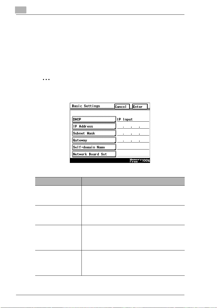
Specify the IP address from the Basic Settings screen.
✎
Note
After changing the settings, turn the unit off, then on again.
1-6
Parameter Description
DHCP Specify whether to automatically retrieve the IP
address from the DHCP server or to specify a
fixed IP address.
IP Address Type in the IP address of this unit.
*Type in the IP address only if the “DHCP”
parameter is set to “IP Input”.
Subnet Mask Type in the subnet mask of the connected
network.
*Type in the subnet mask only if the “DHCP”
parameter is set to “IP Input”.
Gateway Type in the default gateway address of the
connected network.
*Type in the default gateway address only if the
“DHCP” parameter is set to “IP Input”.
Page 10

Before Making Connections and Specifying Settings
1 Press the [Utility] key on the copier control panel.
2 Touch [Administrator Management].
3 Use the keypad to type in the administrator access code, and then
touch [Enter].
4 Touch [Admin. 2].
5 Touch [Network Set].
6 Touch [Basic Setting].
7 Specify the settings described above.
8 Touch [Enter].
✎
Note
In order to apply the new settings, the unit must be turned off, then on
again.
1
1-7
Page 11

1
Before Making Connections and Specifying Settings
1-8
Page 12
Making Connections
2 Making Connections
2.1 LAN Connection
This copier can transmit with the TCP/IP protocol on a LAN. Therefore, the
LAN cable must be connected.
Connect to the LAN by using a LAN cable (cable for Fast Ethernet
100BASE-TX).
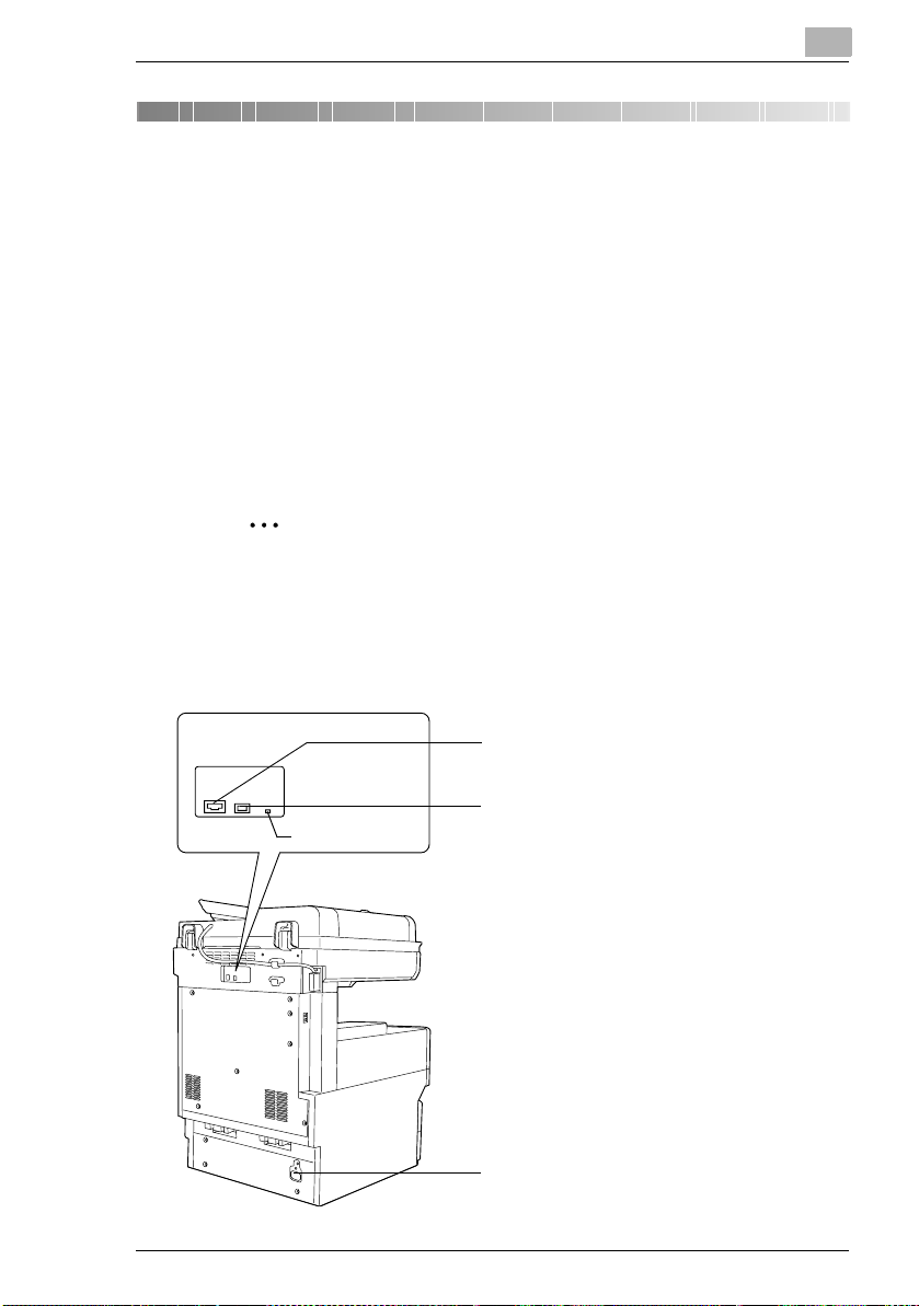
Connecting the LAN cable
Insert one plug on the LAN cable into the connector (marked LAN) at the
back of the machine, and then insert the other plug into the hub.
✎
Tip
The connector is at the back of the machine.
The LAN cable should be a cable for Fast Ethernet 100BASE-TX
(Category 5).
2
The LAN cable is not included as an accessory.
Connector for LAN cable
USB
LAN
LED indicator
USB printer connector (optional)
• For more details, refer to the manual for
the Pi3505e printer controller.
Power cord connector
2-1
Page 13

2
Making Connections
LED indicators
LED Color Condition Meaning
Green Lit The LAN is connected correctly.
Off The copier has not been turned on.
The LAN is not connected correctly.
Flashing Data is being sent or received.
Red Lit Operating at 100 Mbps
Off Operating at 10 Mbps
2-2
Page 14

Making Connections
2.2 Environments for Transmitting Scan Data
The following types of environments are required in order to send scan data.
✎
Tip
In order to use the scanning operations, the Network Interface Card
(NC-4) and the Network Scan Kit (SU-2) or the Internet Fax & Network
Scan Kit (SU-3) must be installed.
All scanning operations can only be used in a TCP/IP network.
Required environment
<Operations that can be performed if the Network Scan Kit is installed>
2
Scan to E-mail
Required options - - - Hard Disk Drive
Required
environment for
image data
transmission
Required
environment for
image data
importing
Mail server FTP server FTP client
Mail client
computer
Scan to
Server(FTP)
FTP client
computer
Scan to PC(FTP) Scan to HDD
Kit
computer
(FTP server
application)
FTP client
computer
(FTP server
application)
-
Web browser
2-3
Page 15

2
Making Connections
<Operations that can be performed if the Internet Fax & Network Scan Kit
is installed>
In addition to the operations that can be performed when the Network
Scan Kit is installed (refer to the above table), the following operations are
available.
Required
options
Required
environment
for image
data
transmission
Required
environment
for image
data
importing
* 1: Di2010 and Di2010f are sold only in the U.S.A. and Canada.
Scan to PC
(SMTP)
----Only with
IP Scanner
and Image
Receiver
utilities
IP Scanner
and Image
Receiver
utilities
Internet
Faxing
Mail server The
Internet fax
terminal
IP Address
Faxing
recipient
must be the
same type
of unit as t he
copier.
The
recipient
must be the
same type
of unit as t he
copier.
IP Scanner
IP Scanner
and Image
Receiver
utilities
IP Scanner
and Image
Receiver
utilities
Distribution
of Fax
Documents
the
Di2010f*
Di2510f,
Di3010f or
Di3510f
Environmen
t required for
the scan
function
selected as
the
distribution
method
1
,
Network
FAX
Only with
the
Di2010f*
Di2510f,
Di3010f or
Di3510f
Network
FAX (EX
Lite) utility
-
1
,
2-4
Page 16

Network Settings
3 Network Settings
The available network operations are limited according to the connected
LAN environment. Specify the network settings according to the
environment and functions to be used.
The network settings can be specified from the copier’s control panel or from
Administrator mode of PageScope Light. The procedure for specifying the
network settings from the copier’s control panel is described below.
For details on specifying PageScope Light settings, refer to the
PageScope Light User Manual.
3.1 List of Network Settings
●: Required; 2: Available
▲: Necessary depending on environment; -: Unnecessary
Operation
3
Scan to E-mail
Scan to
Server (FTP)
Scan to PC (FTP)
Scan to PC (SMTP)
Scan to HDD
IP Scanner
Internet Faxing
IP Address Faxing
Distribution of Fax
Documents
(fax reception)
Parameter
Basic Settings screen
DHCP ▲▲▲▲▲▲▲▲▲▲
IP Address
Subnet
Mask
Gateway ●●●●●●●●●●
Self-domain
Name
Network
Board
Settings
DNS Settings screen
DNS Setting ▲▲▲▲▲ - ▲▲▲ -
Host Name ▲▲▲▲ ▲ - ▲▲▲ -
Domain
Name
DNS Server
Address
●●●●●●●●●●
●●●●●●●●●●
-------2 - 2
▲▲▲▲▲▲▲▲▲▲
▲▲▲▲▲ - ▲▲▲ -
▲▲▲▲▲ - ▲▲▲ -
Network FAX
3-1
Page 17

3
Operation
Scan to E-mail
Scan to
Server (FTP)
Scan to PC (FTP)
Scan to PC (SMTP)
Scan to HDD
Parameter
Equipment Name
Equipment
Name
SMTP Settings screen
SMTP
Server
Address
Port
Number
E-mail
Address
POP3 Settings screen
POP3
Server
Address
Port
Number
POP3 User
Name
POP3
Password
Auto-RX
Check
Mail/Scan Settings screen
E-mail
Mode
Scan Mode 22222 -----
Scanner Settings screen
Activity
Report
RX Doc.
Header
Print
TX Doc.
Text Insert
Gateway
Send
Subject
Registration
222 - 2 - 2 - 2 -
● ▲*
● ▲*
● ▲*
------
------
------
------
------
------222 -
------2 ---
------2 ---
2 -----2 - 2 -
---------
2 -----2 ---
1
--▲*
1
--▲*
1
--▲*
IP Scanner
1
- ● - ● -
1
- ● - ● -
1
- ● - ● -
● ---
● ---
● ---
● ---
● ---
Network Settings
Internet Faxing
IP Address Faxing
Distribution of Fax
Documents
(fax reception)
Network FAX
●
3-2
Page 18

Network Settings
Operation
Scan to E-mail
Scan to
Server (FTP)
Scan to PC (FTP)
Scan to PC (SMTP)
Scan to HDD
IP Scanner
Internet Faxing
IP Address Faxing
Distribution of Fax
Documents
Parameter
Devide
Setting
File Destination Memory Input
File
Destination
Memory
Input
Ping
This function is used to check if the network connection (LAN connection) is correctly connected.
*The ping can be sent with an SMTP server or POP3 server specified. In addition, a ping can be sent with
any IP address specified.
Frame Type Setting
When connecting to the NetWare server and using the PC print function, specify the frame type.
Administrator mode in PageScope Light: [Network]>[FTP Server]>[FTP Configuration]
Proxy
server
address
Proxy port
number
FTP
Connection
Timeout
2 -----2 ---
● --------
-
- ▲ --------
- ▲ --------
- ▲ --------
* 1: If the “URL Notification” function is used, the e-mail transmission (SMTP) settings must
be specified. (Refer to the Scanner Mode User Manual.)
(fax reception)
3
Network FAX
3-3
Page 19

3
3.2 Specifying Network Settings
✎
Note
Before specifying network settings, check with the network
administrator for the necessary information.
Displaying the Network Settings screen
1 Press the [Utility] key on the copier control panel.
2 Touch [Admin.
Management].
Network Settings
3-4
3 Use the keypad to type in
the administrator access
code, and then touch
[Enter].
Page 20

Network Settings
4 Touch [Admin. 2].
5 Touch [Network Set].
3
6 Specify the necessary
settings for the parameters
in the screen that appeared.
❍ Refer to “List of Network
Settings” on page 3-1.
7 Continue touching [Enter] to return to the Utility screen, and then touch
[Exit] to return to the Basics screen.
✎
Note
After changing the setting of a parameter marked with , the copier
must be turned off, then on again.
3-5
Page 21

3
Network Settings
✎
Tip
The list of the settings specified for each function can be printed.
Printing the list of settings
1 Press the [Utility] key, and then touch [Administrator Management].
2 Type in the administrator access code, and then touch [Enter].
3 Touch [Admin. 1], then [Rep. Print].
4 Touch [Setting List].
3-6
Page 22

Installing the Utilities
4
4 Installing the Utilities
This section describes how to install IP Scanner.
For details on installing the Network FAX, refer to the Network FAX User’s
Manual.
4.1 Utilities disk
The utilities disk contains the IP Scanner and Network FAX applications.
In order to install each utility, the amount of hard disk space shown below
must be available.
G IP Scanner: About 5 MB
G Network FAX: About 22 MB
(Network FAX (EX Lite) is not supported by Windows 95.)
4.2 Installing IP Scanner (Windows Me, 98/95, XP, 2000 and NT4.0)
✎
Note
Do not install IP Scanner onto computers used as mail servers or
computers where a mail server is installed.
1 Start up Windows, and then insert the utilities disk (CD-ROM) into the
CD-ROM drive.
The DiALTA Installer starts up, and the DiALTA Installer dialog box
appears.
✎
Tip
If the installer does not start up automatically, double-click “My
Computer” on the desktop, and then double-click the icon for the
CD-ROM drive containing the CD-ROM. Double-click [setup.exe]
on the CD-ROM to start up the installer.
4-1
Page 23

4
Installing the Utilities
2 Click the [GO] button beside Install IP Scanner.
✎
Note
The dialog boxes that appear may differ depending on the
operating system.
4-2
3 Check the contents of the dialog box, and then click the [Next] button.
Page 24

Installing the Utilities
4 Check the contents of the dialog box, and then click the [Yes] button.
✎
Note
If you do not agree with the license agreement, IP Scanner cannot
be installed.
Check the provisions of the agreement, and then click the [Yes]
button.
5 Check which folder IP Scanner will be installed into, and then click the
[Next] button.
4
❍ To change the folder where IP Scanner will be installed, click the
[Browse...] button, and then select the desired folder.
❍ While specifying settings in the installer dialog boxes, if you
choose the wrong setting or want to change a setting, click the
[Back] button to return to the previous dialog box and specify the
settings as desired.
4-3
Page 25

4
Installing the Utilities
6 Select the folder where IP Scanner will be registered, and then click
the [Next] button.
The installation begins.
7 Click the [Finish] button.
4-4
A message may appear, informing you that the computer should be
restarted.
Restart the computer to complete the installation.
Page 26

Installing the Utilities
8 In the DiALTA Installer dialog box, click the [Close] button.
9 Restart the computer.
4
❍ Click the [Yes] button to restart the computer.
4-5
Page 27

4
4.3 Uninstalling IP Scanner
Uninstalling IP Scanner (Windows Me, 98/95 and NT4.0)
✎
Note
Quit Image Receiver before uninstalling IP Scanner.
1 In Windows, click the [Start] button, point to [Settings], and then click
[Control Panel] to display the Control Panel window.
2 Double-click the [Add or Remove Programs] icon.
3 Select “IP Scanner”, and then click the [Add/Remove...] button.
Installing the Utilities
4-6
4 Click the [Yes] button.
5 Restart the computer.
Page 28

Installing the Utilities
Uninstalling (Windows XP and 2000)
✎
Note
Quit Image Receiver before uninstalling IP Scanner.
1 In Windows, click the [Start] button, point to [Settings], and then click
[Control Panel] to display the Control Panel window.
2 Double-click the [Add/Remove Programs] icon (the [Add or Remove
Programs] icon in Windows XP).
3 Select “IP Scanner”, and then click the [Change/Remove] button.
4
4 Click the [Yes] button.
5 Restart the computer.
4-7
Page 29

4
Installing the Utilities
4-8
Page 30

Features of the Network Functions
5 Features of the Network Functions
Paper documents can easily be converted to electronic data and used, for
example, with electronic filing. Scanned image data (scan data) can be
sent to other computers through a network as either a TIFF file or a PDF
file.
The scanned image can be sent using any of the following methods.
Choose the appropriate method according on the network environment
and purpose.
5.1 Scan to E-mail
G Scan data is attached to an e-mail message as a TIFF or PDF file, then
sent to a computer through an intranet or the Internet.
G A network environment that includes a mail server is required.
Mail server
Client computer
5
Mail server
Intranet
Internet
Client computer
5-1
Page 31

5
5.2 Scan to Server (FTP)
G Scan data can be uploaded as TIFF or PDF files to a specified
directory on an FTP server.
G A network environment that includes an FTP server is required.
G An FTP server on the Internet can be accessed through a proxy
server.
G A maximum of five FTP server can be registered, and a maximum of
five directories can be set up on each FTP server.
Features of the Network Functions
FTP server
Intranet
5-2
Internet
FTP server
Page 32

Features of the Network Functions
G With the “URL Report” function, a notification of the URL where the
scan data is saved can be sent by e-mail. (If the “URL Report” function
is used, a mail server is required.)
5
FTP server
FTP server
Internet
Client computer
Intranet
Internet
Mail server
Client computer
5-3
Page 33

5
5.3 Scan to PC (FTP)
G Scan data can be sent as TIFF or PDF files to client computers using
FTP.
G The FTP server application must be running on the client computers.
G The forwarding destination on the client computer is the root folder
specified with the FTP server application. This setting cannot be
specified from the copier's control panel or from PageScope Light.
Features of the Network Functions
FTP server
application
Intranet
Client computer
5-4
Page 34

Features of the Network Functions
5.4 Scan to HDD
G Scan data is saved on the copier's hard disk as TIFF or PDF files.
The saved files can be retrieved with PageScope Light.
G With the “URL Report” function, a notification of the URL where the
scan data is saved can be sent by e-mail.
(If the “URL Report” function is used, a mail server is required.)
Scan
data
HDD
Intranet
Client
computer
5
5-5
Page 35

5
5.5 Internet Faxing
G As opposed to a normal fax, which transmits through telephone lines,
Internet fax sends and receives fax images through the Internet.
Internet fax uses the Internet electronic mail (e-mail) setup to send and
receive fax images. Image data scanned at an Internet fax terminal is
attached to an e-mail message as a TIFF-F file, then sent to the
recipient's Internet fax terminal. The file attached to the received email message is printed by the Internet fax terminal on the receiving
end.
In addition, since e-mail is used, the fax can be sent to an individual email address, not just an Internet fax terminal. In this case, the fax
image arrives at the receiving end as an attachment to an e-mail
message received with the usual mail client software.
Features of the Network Functions
Mail server
Client computer
Internet fax
terminal
5-6
Intranet
Internet
Mail server
Client computer
Page 36

Features of the Network Functions
5.6 IP Address FAX (LAN-FAX)
G Scan data is sent to a copier of the same type (Internet fax) through
the Internet, without passing though a mail server.
Intranet
1 Program a one-touch key with the IP address or the host name of the
recipient.
5
Internet fax terminal
(Same type of unit
as copier)
2 Use the one-touch key to specify the recipient, and then specify the
settings for sending the data (IP address fax transmission).
3 The recipient receives the fax image (IP address fax reception).
5-7
Page 37

5
5.7 Scan to PC (SMTP)
G Scan data can be sent as TIFF or PDF files to client computers using
SMTP.
G From the client computer, the enclosed IP Scanner application must
be used to first specify the folder where data is saved. In addition, the
IP Scanner application can be set to save the data in a folder that was
created using the name of the one-touch key.
G In order to receive the data at a client computer and save it as an
image file, the enclosed utilities IP Scanner and Image Receiver are
required.
G If there is a DHCP server on the network, this function may not operate
correctly since IP addresses are automatically distributed to each
computer. In this case, specify a fixed IP address for the computer or
use IP Scanner.
Intranet
Features of the Network Functions
Client computer
5-8
1 Program a one-touch key with the IP address of the computer
receiving the data.
2 Using the same procedure for sending e-mail messages, specify that
the data is to be sent to a computer.
3 The sent scan data is received by the recipient computer.
4 The IP Scanner application converts the data to a TIFF or PDF file,
then saves the file in the specified folder.
Page 38

Features of the Network Functions
5.8 IP Scanner
G Scan data is sent to a client computer, where it is saved in a folder that
is created using the name of the scanner button.
G After programming a button (Scan data destination and scan settings)
from the client computer when scanning, a paper document can easily
be saved as an electronic file with just the touch of a button in the
copier’s touch panel.
In order to receive the data at a client computer and save it as an
image file, the enclosed utilities IP Scanner and Image Receiver are
required.
G This function can be used in a network without a LAN if a crossover
cable is used to connect the copier to a client computer. (Network
settings are required.)
5
Client computer
1 From the computer, program a button (recipient of the scan data).
2 Touch the programmed button to send the scan image.
3 The sent scan image is received by the recipient computer.
4 The IP Scanner application converts the data to a TIFF or PDF file,
then saves the file in the specified folder.
5-9
Page 39

5
Features of the Network Functions
5.9 Document Forwording/Archive Distribution
G Image data received from a fax machine on a common telephone line
can be sent directly to a computer or attached to an e-mail message.
In order to transmit the fax document by e-mail, a network environment
that includes a mail server is required.
G The fax document can be be received at your own computer.
G Received fax documents can be classified as “F-Code”, “Port” or
“Public Document”, and the distribution destinations for each type of
document can be specified.
Facsimile
terminal
Facsimile
communication
Telephone
line
Client computer
Mail server
1 From the copier, select a Doc. Manage setting to classify the fax
image.
2 The fax image is sent to the computer specified as the recipient.
3 The fax image is received by the recipient computer as an image file.
5-10
Page 40

Features of the Network Functions
5.10 Network Fax Transmission
G To use Network Fax transmission, “Network FAX” is required, one of
the attached utilities. Be sure to confirm the network environment, then
perform the network setting and the setup of Network FAX.
G A document created in an application, such as word-processing
software, can be faxed by specifying the telephone (fax) number of the
recipient, without first printing the document.
In addition, the result of the fax transmission can be checked from the
computer.
G An e-mail address or a telephone (fax) number can be specified for the
recipient.
G In order to perform direct faxing operations using a mail server, the
DNS settings must be specified.
Client computer
5
Mail server
Telephone
line
Facsimile
communication
Facsimile terminal
1 Specify the fax number of the destination (specify the recipient after
specifying printing from the application).
2 The image data is transmitted from the client computer or mail server.
3 The data received by the computer is sent to the specified fax number.
5-11
Page 41

5
Features of the Network Functions
5-12
Page 42

Using PageScope Light
6 Using PageScope Light
PageScope Light is a utility for managing devices supported by the HTTP
server integrated into the printer/scanner controller. Using a Web browser,
PageScope Light can remotely control the printer/scanner controllers on
the network.
6.1 System Requirements
The following operating environment is required in order to use
PageScope Light.
Computer (Software)
Operating System Web Browser
Windows 95/98/Me/NT4.0 Internet Explorer 4 or later
Windows 2000 Internet Explorer 5 or later
Windows XP Internet Explorer 6 or later
MacOS 8.6 or 9.x Internet Explorer 4.5 or later
MacOS X Internet Explorer 5.1 or later
Netscape Communicator 4.7 or later
Netscape Navigator 7.0
Netscape Navigator 7.0
Netscape Navigator 6.1 or later
Netscape Navigator 6.1 or later
6
Network
G Ethernet
G TCP/IP protocol
Di3510/Di3010/Di2510/Di2010/Di3510f/Di3010f/Di2510f/Di2010f
Network Interface Card
Any of the following options must be installed.
G Pi3505e Printer Controller
G Pi3505e/PS Printer Controller
G Network Scan Kit
G Internet Fax & Network Scan Kit
6-1
Page 43

6
✎
Note
The dialog boxes shown in this manual may differ from those that
appear on your computer. In addition, the specifications and other
information concerning this product may change without notice.
6.2 Accessing PageScope Light
✎
Note
In order to use PageScope Light, the IP address must be set in
advance. (Refer to “Specifying the IP Address” on page 1-6.)
PageScope Light can be accessed through a Web browser.
1 Start up the Web browser.
2 In the Address bar, type the IP address of the controller in the format
shown below, and then press the computer keyboard's [Enter] key.
http://controller_IP_address/
(Example) If the controller IP address is 192.168.0.10:
http://192.168.0.10/
Using PageScope Light
6-2
3 The initial page of PageScope Light appears.
✎
Note
If your Web browser is set to use a proxy server, it may not be able to
access PageScope Light. In this case, specify the IP address of the
printer/scanner controller as an exception for access through the
proxy server.
(Example) With Internet Explorer 5
1 Click [Tools] in the menu bar, and then click [Internet Options....].
2 Click the [Connections] tab.
3 Click the [LAN Settings] button.
4 Click the [Advanced] button in the “Proxy server” group box.
5 Type the IP address of the printer/scanner controller into the
“Exceptions” list box.
Page 44

Using PageScope Light
6.3 Using PageScope Light
PageScope Light is used in the same way that Internet Web pages are
viewed. Click Web page links to display those pages, or click the [Back]
(or [Forward]) button to display the previous (or next) page.
6.4 Logging Into Administrator Mode
By logging into PageScope Light in Administrator mode, printer/scanner
controller system settings can be specified or checked.
1 In the Admin Password box in the upper-left corner of the page, type
the administrator password.
2 Click the [Log-in] button to log into the Administrator mode.
6
6-3
Page 45

6
Using PageScope Light
3 To log out, click the [Log-out] button.
✎
Note
For the administrator password, use the administrator access code for
the copier. For details, contact the administrator for your copier.
6-4
If no operation is performed for 10 minutes after logging into
PageScope Light in Administrator mode, the user is automatically
logged out.
While logged into PageScope Light in Administrator mode, not all
operations can be performed from the copier’s control panel.
Page 46

Using PageScope Light
6.5 Selecting the Display Language
If necessary, the language in which PageScope Light pages are displayed
can be changed. This setting only applies to PageScope Light pages.
1 Log into PageScope Light in Administrator mode.
2 Click [Preference] in the menu on the [System] tab.
3 From the PageScope Light Language list, select the desired
language.
4 Click the [Apply] button.
6
6-5
Page 47

6
6.6 Structure of Pages
The following page (called the User mode page) can be viewed by
anyone. If the administrator password is typed into the Admin Password
box on the User mode page, the Administrator mode page can be
displayed.
The pages of PageScope Light are constructed as shown below.
Using PageScope Light
1
3
5
1 Minolta PageScope
Light logo
2
4
6
Click the Minolta logo to go to the following
Web site.
www.minolta.com
Click the PageScope Light logo to display the
version information in a separate window.
6-6
The version and copyright information for
PageScope Light appear in this window.
Click the Minolta logo to go to the Minolta
Web site.
Click the PageScope Light logo to go to the
PageScope Web site.
Page 48

Using PageScope Light
2 Status display The statuses of the printer and scanner are
3Admin Password
box
4 Tabs The categories that can be controlled by
shown with text and icons.
In addition, the status warnings for the printer
and scanner appear as messages.
To view the most recent status messages,
click the [Refresh] button in the Web browser.
Use to log in Administrator mode. (For details
on the login procedure, refer to “Logging in
Administrator mode” in the PageScope Light
User Manual.)
PageScope Light are displayed.
User mode
• System
• Job List
1
• File*
• Print*
• Scan*
2
3
Administrator mode
• System
4
• File*
• Print*
• Scan*
2
3
• Network
6
For details on each tab, refer to the
“PageScope Light Users Manual”.
1
*
Available only if the network scan kit is
installed
*2 Available only if the printer controller is
installed
3
Available only with the Di3510f, Di3010f,
*
Di2510f or Di2010f, or if the network scan kit
or internet fax & network scan kit is installed
4
Available only if the hard disk drive kit and
*
the network scan kit are installed
5 Menu The information and setting items for the
selected tab are listed.
For details on each menu, refer to the
“PageScope Light Users Manual”.
6 Information and
settings
The details of the item selected from the
menu are displayed.
6-7
Page 49

6
Using PageScope Light
6-8
Page 50

2003 MINOLTA CO., LTD.
The information contained in this manual
is subject to change without notice to
incorporate improvements made on the
product or products the manual covers.
Copyright
Printed in Japan
2003. 6
3-13, 2-chome, Azuchi-Machi, Chuo-ku, Osaka. 541-8556, Japan
MINOLTA CO., LTD.
ND-100102(E)
2003. 6 ISSUE 1
 Loading...