

Page 1

Pi4700e
SERVICE MANUAL
Page 2

CONTENTS
GENERAL, MECHANICAL/ELECTRICAL
1. SPECIFICATION ............................................................................................. M-1
1-1. Controller Specifications .......................................................................... M-1
1-2. Supporting Client Specifications ..............................................................M-3
(1) IBM PC and Compatible Computers ............................................... M-3
(2) Apple Macintosh Computers ........................................................... M-3
1-3. Applicable Browser Specifications ...........................................................M-3
(1) Utility Functions ...............................................................................M-3
2. APPEARANCE ................................................................................................ M-3
3. COMPONENTLAYOUT ................................................................................... M-4
4. SYSTEM CONFIGURATION ...........................................................................M-5
5. CONTROLLER START-UP .............................................................................M-6
6. LEDs and DIP SWITCHES .............................................................................. M-7
6-1. LEDs on the Main Board .......................................................................... M-7
6-2. DIP Switches on the Main Board ............................................................. M-8
7. NIC BOARD (OPTION) ....................................................................................M-9
7-1. Display of LEDs on the NIC Board ......................................................... M-9
(1) NIC Board ........................................................................................M-9
(2) Normal Operating States ................................................................. M-9
(3) When an Error Occurs .....................................................................M-9
7-2. Jumpers on the NIC Board ......................................................................M-10
DIS/REASSEMBLY, ADJUSTMENT
1. DISASSEMBLY/REASSEMBLY ...................................................................... D-1
1-1. Remove from the Copier .......................................................................... D-1
1-2. Removal and Replacement of a DIMM ....................................................D-4
1-3. Removal of the NIC Board (Option) .........................................................D-4
1-4. Removal of the HDD (Option) ..................................................................D-5
1-5. Removal of the Main Board .....................................................................D-6
1-6. Checking of the optional memory installation .......................................... D-7
1-7. Mode Setting ............................................................................................ D-7
TROUBLESHOOTING
1. INTRODUCTION ............................................................................................. T-1
1-1. General Precautions ................................................................................ T-1
1-2. Reading the Text .....................................................................................T-1
1-3. Network Problems ................................................................................... T-1
2. STATUS CODES .............................................................................................T-2
3. REMEDIAL PROCEDURES ............................................................................ T-4
3-1. Printing is Not Possible Via Parallel Port ................................................. T-4
(1) Checking Printer cable for connection .............................................T-4
(2) Checking power harness for correct voltage ...................................T-4
(3) Checking controller connector (J2) for proper connection to Image
Processing Board ............................................................................T-5
(4) Checking DIP switch settings and connectors on Main Board ........T-5
3-2. Printing is Not Possible Via Network ....................................................... T-5
i
Page 3

(1) Checking cable and connector for connection .................................T-5
(2) Checking LEDs on the NIC Board ................................................... T-5
4. CONTROLLER WIRING DIAGRAM ................................................................ T-6
5. MAIN BOARD COMPONENT LAYOUT ..........................................................T-7
6. Controller Firmware Update Instructions .........................................................T-8
ii
Page 4

GENERAL,
MECHANICAL/ELECTRICAL
Page 5

1. SPECIFICATION
1-1. Controller Specifications
Type : Printer controller built into copier
Print Speed : Determined by the specification of the digital copier.
Printer Language : PCL5e
PCL6
PostScript 3 Emulation
CPU : IBM PowerPC 740 (200 MHz)
ASIC : IBM printer ASIC
ROM : Capacity: 8 MB, Flash ROM (including alphabet fonts
and PCL/PS program)
RAM : Standard 32 MB (On Board)
HDD : 2.5 inch IDE interface (Option)
Host Interface : Conforming to IEEE1284
Network Connection : 10/100BaseT (Option)
Copier Interface : Minolta’s unique Dual Port RAM
Network Type : Print Server Card
Network Protocol : IPX/SPX: NetWare 4.x & 5.x
Network Management : PageScope Light
Printer controller to NIC interface : DP0
Applicable paper sizes : Max. standard paper A3
Transfer Image Density : 600 × 600 dpi
Power : 5 V ± 3 %, 5 A or less (supplied from copier)
Maximum Power : 20 W or less
PC Board : 290 mm × 154 mm, 6 layers, glass epoxy
Operating Environmental
Conditions
Fonts : PCL6
(expandable up to 160 MB)
Minolta’s unique Image DATA DMA
Novell (Generic) NDPS Gateway-compatible
TCP/IP: LPD (Windows), IPP
AppleTalk: PAP (Macintosh) Suppor ting EtherTalk only
3.3 V ± 3 %, 2 A or less (supplied from copier)
: Temperature: 10 to 35 °C
Humidity: 15 to 85 %
• Agfa Intellifont 35
• True Type font 10
Postscript 3 Emulation
• Type1 font 136
M-1
Page 6

Standard Accessories : <CD-ROM>
PCL6 Printer Driver
• Windows 95
• Windows 98/Me
• Windows NT4.0
• Windows 2000/XP
PS Printer Driver
• Windows 95/98/Me
• Windows NT4.0
• Windows 2000/XP
• PPD file for Macintosh
• PPD Plugin for Mac OS X
Linux Utility
• Redhat Ver. 6.1, 6.2
• Suse Ver. 6.3, 6.4
• Turbo Ver. 4.0, 6.0
• Open Ver. 2.3, 2.4
Font Manager Ver. 2.0
Option : <Network Cards>
• 10/100BaseT (95 × 125 mm)
• NIC interface cable
• Metal tube (two)
<Expansion Memory Specification>
168pin SDRAM DIMM, +3.3V, 128MB or 64MB, CL2,
PC100 or higher
The following specifications are a list of the items that
have completed operation checks.
<Memory Card Technology>
• 64 MB ML64L4 (Samsung chips)
• 64 MB ML64L4 (Hyundai chips)
• 64 MB ML64L4 (IBM chips)
<Delkin Device>
• 64 MB MINRAM8-064 (DM168-064Y3Q488-10S2P)
• 128 MB MINRAM8-128 (DM168-128Y3Q468-10S2P)
<Wichmann WorkX AG>
• 64 MB MXM64/MIP352:168
• 64 MB MXM64/MIP352:200
• 128 MB MXM64/MIP352:168
• 128 MB MXM64/MIP352:200
<Hard Disk Drives>
This option is used for downloading Mac PS fonts and
storing them.
• 2.5 inch, 10-GB, IDE interface specifications
• Mounting bracket
• IDE interface cable
M-2
Page 7
1-2. Supporting Client Specifications
(1) IBM PC and Compatible Computers
CPU : Pentium or more
Memory : 64 MB or more
OS : U.S. version Windows 95/98/Me/NT4.0/2000/XP
Miscellaneous : Should have sufficient memory and resources in the above Windows
(2) Apple Macintosh Computers
CPU : PowerPC
Memory : 16 MB or more
OS : MacOS System7.5.3 or later, 8.x and 9.x, OS X (10.2 or later)
Redhat Linux Ver. 6.1, 6.2
Suse Linux Ver. 6.3, 6.4
Open Linux Ver. 2.3, 2.4
Turbo Linux Ver. 4.0, 6.0
and other applications used.
1-3. Applicable Browser Specifications
(1) Utility Functions
• Netscape communicator Ver. 4.7 or later
• Internet Explorer version 5.0 or later
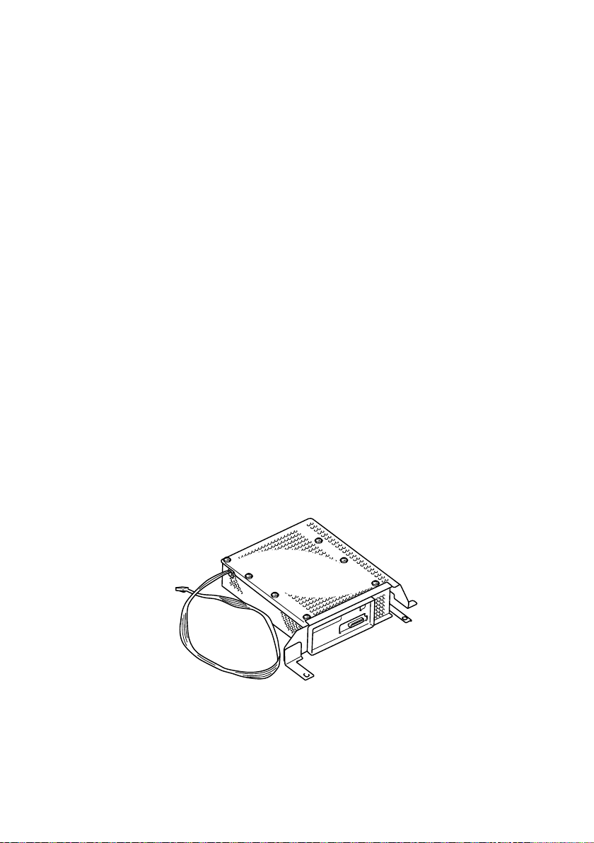
2. APPEARANCE
4692U001AB
M-3
Page 8
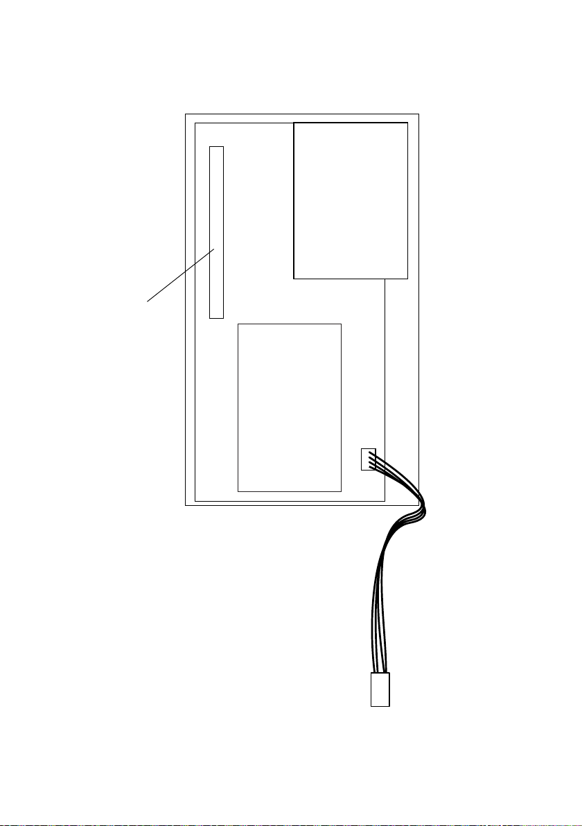
3. COMPONENTLAYOUT
NIC Board (Option)
64 MB DIMM (Option)
128 MB DIMM (Option)
Main Board
HDD (Option)
M-4
Power Supply
Harness
4692M501CB
Page 9
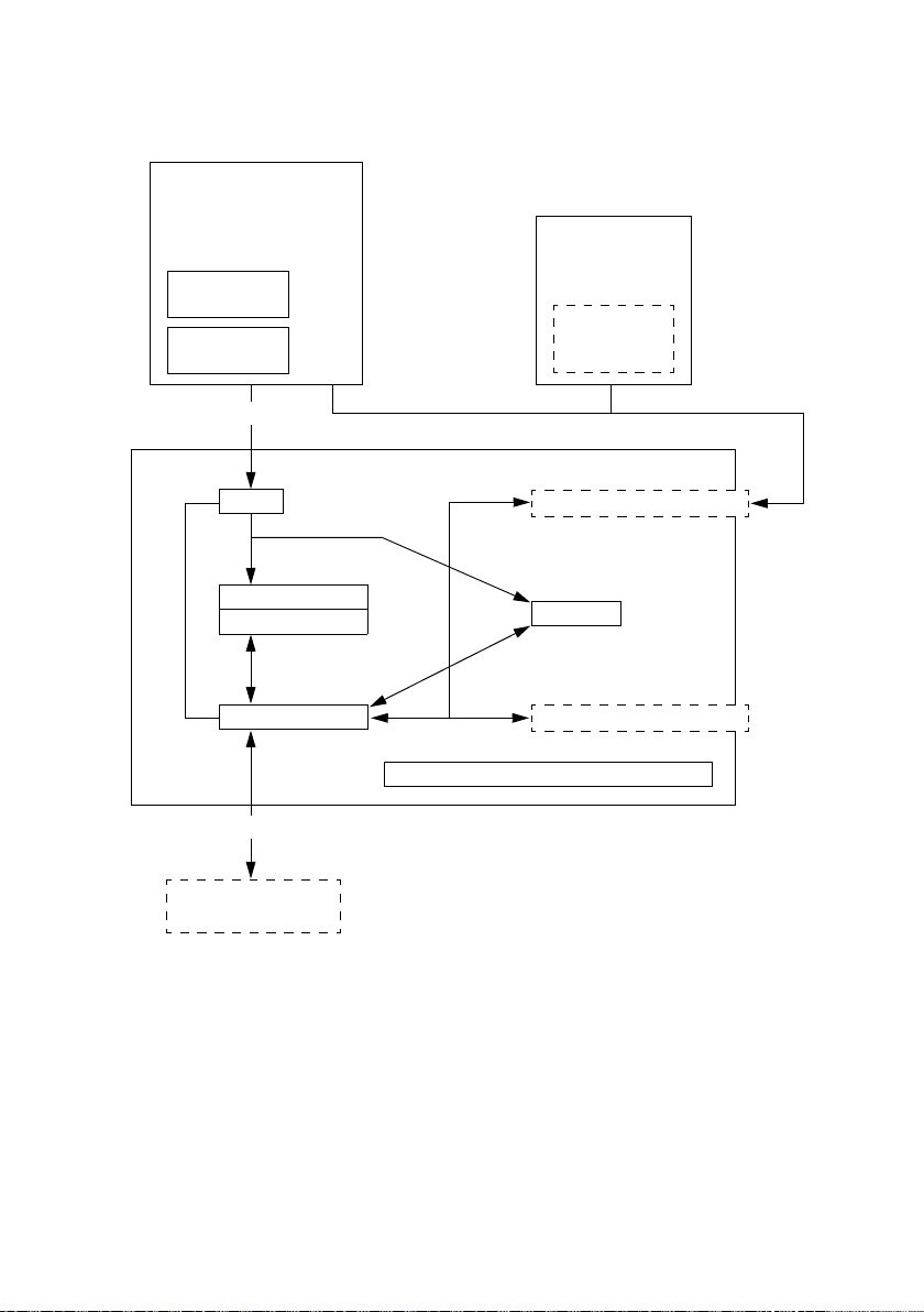
4. SYSTEM CONFIGURATION
• Controller System Configuration
PC
Windows 95/98/Me/2000/
XP
Windows NT4.0
PCL6
Print Drive
PS
Print Drive
Apple Macintosh
PS
Print Drive
PPD File
Centronics
PJL
PCL5e Emulation
PCL6 Emulation
Device Driver
Minolta’s Unique Interface
Digital Copier
NIC Board (Netsilicon.Co)
PS Core
Hard Disk Drive (HDD)
OS
Ethernet
Definitions
PS : Abbreviation for PostScript, a page description language developed
by Adobe Systems, Inc.
Centronics : A parallel interface standard for connecting printers.
Ethernet : A data transfer protocol used in information networks.
PJL : Abbreviation for Print Job Language, a system that interprets the
language used by the input signal.
M-5
Page 10

5. CONTROLLER START-UP
• Turning ON the power switch of the copier with the controller power cable connected to
the copier lets the controller perform the start-up procedures.
1. Power-ON reset
2. Initializes the processor and memory controller.
3. Memory clear (areas required for boot and the dual port RAM for engine I/F)
4. Copies boot loader to RAM.
5. Initializes I/O (Flash Rom and serial port).
6. Copies compressed OS image from Flash Rom to RAM.
7. Uncompresses compressed image.
8. Starts VxWorks.
M-6
Page 11

6. LEDs and DIP SWITCHES
6-1. LEDs on the Main Board
• Each of the LEDs on the Main Board turns ON to indicate the following state of the controller.
LED0
LED1
LED2
LED3
LED4
4692M502AA
LED Controller State
LED0 PDL data being received (parallel, network)
LED1 Packet being transmitted to the copier
LED2 Packet being received from the copier
LED3 Print image data being transmitted to the copier
LED4 Scan image data being received from the copier
LED5 Reserved
LED6 Reserved
LED7 Reserved
M-7
Page 12

6-2. DIP Switches on the Main Board
• DIP switch keys are flipped to the ON and OFF positions to set different states as
detailed below when the copier is turned ON.
DIPSW2
DIPSW3
DIPSW1
DIPSW4
4692M503AA
Purpose DIPSW1 DIPSW2 DIPSW3 DIPSW4
Controller diagnostics 1 OFF ON OFF OFF
Controller diagnostics 2 OFF OFF ON OFF
To return controller NVRAM to the factory
settings.
OFF OFF OFF ON
NOTE
• These are the only permissible combinations of DIP switch key settings. NEVER attempt
to make any other combination.
M-8
Page 13

7. NIC BOARD (OPTION)
7-1. Display of LEDs on the NIC Board
(1) NIC Board
Amber LED
Green LED
(2) Normal Operating States
Operation Green LED Amber LED
Self-test being carried out when the printer is
turned ON.
NIC is operating properly while the printer
awaits a print job.
At the end of printer self-test
Printer initialization sequence is completed.
A network print job is received.
Network connection is disconnected.
OFF: ❍, ON: ●, Blinking:
(3) When an Error Occurs
Description Green LED Amber LED
A hardware error occurs
OFF: ❍, ON: ●, Blinking:
The green LED flashes OFF and ON once to 12 times, then the amber LED flashes OFF
✽
and ON once to 7 times.
4668M004AC
●❍
●❍
❍
❍
●
●❍
M-9
Page 14

7-2. Jumpers on the NIC Board
CS1
JP2
CS2
10/100 BaseT
FACT
BYPASS
TEST
ON
ON
T.B .
P. A .
OP7
OP5
OP4
OP3
OP2
OP6
OP1
4668M502CA
NOTE
• Never change the positions of pins shown in black in the above figures (initial settings).
M-10
Page 15

DIS/REASSEMBLY,
ADJUSTMENT
Page 16

1. DISASSEMBLY/REASSEMBLY
1-1. Remove from the Copier
NOTE
• Whenever attempting to remove the controller from the copier, be sure to unplug the
power cord the copier.
1. Remove nine screws and the Rear Cover.
NOTE
• The type of the screw on the lower right corner is different from the others.
4002U036AA
2. Remove seven screws and the Left Cover.
D-1
4002U037AA
Page 17

3. Remove thirteen screws and the exterior cover.
4692U013AB
NOTE
• Pressing the controller in the direction shown by the arrow, install it so that gasket of the
cover is folded inside.
Gasket
4. Unplug the power connector.
4692U030AA
4692U028AB
4692U010AA
D-2
Page 18

5. Remove four screws, unplug one connector, and remove the controller.
4692D501AA 4692U012AB
NOTE
• Install the controller according to the procedure.
1. Plug in the connector.
2. Pressing the controller in the direction shown by the arrow, secure it in position.
4692D502AA 4692D513AA
D-3
Page 19

1-2. Removal and Replacement of a DIMM
1. Remove the exterior cover.
2. Disengage the removal levers on both sides.
3. Pull the DIMM straight upward.
NOTES
• A DIMM has a unique orientation at installation. Note that the cutout in the DIMM is
located as illustrated bellow.
• Be sure to insert the board until it locks into position.
• Static electricity can destroy electronic components. Touch a metal or similar object with
your hand before starting the procedure.
Cutout
4692D503AA
1-3. Removal of the NIC Board (Option)
1. Remove the exterior cover.
2. Unplug the connector from the NIC Board.
3. Remove two screws from the outer end, two screws from the NIC Board, and the NIC
Board.
NOTE
• When removing the NIC Board, use care not to touch the ICs and patterns on the board.
4692D508AA
D-4
Page 20

1-4. Removal of the HDD (Option)
1. Remove the exterior cover.
2. Remove four screws and the HDD mounting bracket.
3. Unplug the connector from the Main Board.
4. Remove four screws and the HDD.
5. Remove the HDD cable.
4692U011AB
4692D505AA
NOTE
• When plugging in the HDD cable, its left edge should be flush with the left edge of the
mating connector and there are four pins which have no mating parts on the right-hand
side.
4668U008CA
D-5
Page 21

1-5. Removal of the Main Board
1. Remove the exterior cover.
2. Remove the HDD.
3. Remove the NIC Board.
4. Unplug the power connector.
5. Remove eight screws, unplug one connector, and the Main Board.
4692U010AA
4692D501AA
4692D506AA
D-6
Page 22

1-6. Checking of the optional memory installation
NOTE
• If the 32 MB Memory is installed in the copier, “64 M” is shown in the left column. If “64
M” is not shown on the screen, install the 32 MB Memory to the copier.
1. Select “Tech. Rep. Mode” → “Function”→ “Image Memory”→ “Opt. Mem. Check”.
2. Confirm the indication in the left column on the Opt. Mem. Check screen.
1-7. Mode Setting
1. Call the Tech. Rep. Mode to the screen.
(See Service Manual for the procedure to access
the Tech. Rep. Mode.)
2. Touch [Tech. Rep. Choice].
4002P523CA
3. Touch [Controller Set].
4692P256CA
4. Touch [Controller Type].
5. Press “C” and “6” on the 10-key pad.
6. Touch [END].
7. Touch [Peripheral Mode].
8. Touch [Mode 1] or [Mode 3].
Mode 1: Scan to E-mail/Server
4692P254CA
Mode 3: No selection of Scan function
(No Network Interface Card is installed)
9. Press the Panel Reset key and touch [EXIT].
D-7
Page 23

TROUBLESHOOTING
Page 24

1. INTRODUCTION
1-1. General Precautions
• When replacing a part or plugging or in unplugging a connector, always make sure that
the power cord of the copier has been unplugged.
• Never create a closed circuit across connector pins except those specified in the text and
on the printed circuit.
• When energizing the controller with its cover removed, use utmost care not to touch a
board or any other component inside it.
• The basic rule is not to run the controller with any of its parts removed.
• When the user is using a word processor or personal computer from the power outlet of
the same line, take necessary steps to prevent the circuit breaker from opening due to
overloads.
• Keep all disassembled parts in good order and keep tools under control so that none will
be lost or damaged.
1-2. Reading the Text
• If a component (except fuses) on a PWB or any other functional unit including the HDD is
defective, the text only instructs you to replace the whole PWB or functional unit and
does not give troubleshooting procedures applicable within the defective unit.
• All troubleshooting procedures contained herein assume that there are no breaks in the
harnesses and cords and all connectors are plugged into the right positions.
• The text does not contain the removal procedures of covers and parts. See DIS/REASSEMBLY of the Service Manual for copier.
• The procedures preclude possible malfunctions due to noise and other network problems.
1-3. Network Problems
• Any problem that occurs in conjunction with the operation of the controller over a network
should be directed to the network administrator for check and repair. The servicemen
should never attempt to make network-related settings or repair network-related problems.
• The user should only ask for a check on network-related wiring from the network to the
controller and should never attempt to check it out him/herself.
T- 1
Page 25

2. STATUS CODES
• If the controller is ready to communicate, it notifies the copier of the code (18XX).
Code Description Action
NVRAM error:
• A fault is found in retention of the setting values stored in the
18A0
18A1
18A3
18A4
18A5
18A6
18A7
18A8
18B8
18C0
18C1
controller NVRAM.
• A mismatch is detected in version numbers.
• Factory settings are recovered through DIP switch setting.
NIC error:
NIC initialization has failed.
Version error:
A mismatch is found between the program utility function version and ROM disk utility function version.
Flash ROM update data being loaded:
The controller notifies, after accepting a flash ROM update
request, that update data is being downloaded. It has suspended some of its functions and the job being processed can
be terminated or discarded.
The power should not be shut down while this notification is
✽
being issued.
Flash ROM update data being written:
The controller notifies that update data, which has been downloaded, is being written in flash ROM.
The power should not be shut down while this notification is
✽
being issued.
Flash ROM update completed:
The controller notifies that writing of update data in flash ROM
has been completed.
Flash ROM update data loading failure:
The area required for downloading update data is not available
or there is an error found in update data.
Flash ROM update data writing failure:
Writing in flash ROM has failed.
The data in ROM might have been destroyed and it is likely
✽
that the controller cannot recover.
Scan job abandoned for short of machine memory space:
Short machine memory space results during distribution involving two or more distribution destinations.
Reset 10 min. later or at the start of the next scan job.
✽
Short of memory space during image conversion:
A job is abandoned for short of controller memory space during
processing of scan jobs.
Reset 10 min. later or at the start of the next scan job.
✽
Scan job NIC internal processing error:
Distribution is interrupted by an error response from NIC during
distribution processing of scan jobs.
Reset 10 min. later or at the start of the next scan job.
✽
✽
✽
✽
✽
✽
Reset
Reset
—
—
—
Reset
Reset
Reset
—
—
—
T- 2
Page 26

18C2
18D0
18D1
18F1
18F2
Reset
✽
• Operate PageScope Light to reset.
• Switch the copier off then do it on.
Scan job Controller internal processing error:
Reset 10 min. later or at the start of the next scan job.
✽
Hard disk being formatted:
Hard disk is formatted if the controller determines that the
mounted disk is yet to be formatted upon startup or when a
request is made from utility.
Reset when formatting is completed.
✽
Hard disk formatting error:
Formatting of hard disk has failed.
Reset when formatting performed again is successful.
✽
Copier communication error:
An error is detected in communications with the machine during the course of a connect command being issued at regular
intervals for connection check after a power-ON sequence with
the machine has been completed.
Controller fatal error:
The controller notifies the copier that some of the functions are
currently disabled because of a fatal error it has detected.
Neither notification to the copier nor any others to the copier
✽
after this notification is guaranteed.
✽
✽
—
—
—
Reset
Reset
T- 3
Page 27

3. REMEDIAL PROCEDURES
• The basic repair procedure for the controller is to replace the defective PC board or other
unit with a new one.
• First, identify the faulty symptom and replace the defective part to restore the controller
to the normal operating condition.
3-1. Printing is Not Possible Via Parallel Port
Step Check Result Action
1 Check the printer cable for proper
connection.
2 Check the power harness for correct
voltage.
3 Check the controller connector (J2)
for proper connection to the Image
Processing Board.
4 Check DIP Switch settings on, and
connector connection to, the Main
Board.
(1) Checking Printer cable for connection
• After turning the copier power OFF, check the printer cable for proper connection to the
controller. Then, turn the copier power ON again.
NG Reconnect cable and turn ON the
copier power again.
OK Go to step 2.
NG Change the DC Power Supply Main
of the machine.
OK Go to step 3.
NG Reconnect connector and turn ON
the copier power again.
OK Go to step 4.
NG Correct faulty spots and turn ON the
copier again.
OK Change the Main Board.
Printer Cable
(2) Checking power harness for correct voltage
• When the Power Switch is turned ON:
Voltage across Main Board J11-1 and GND: DC 5 V
Voltage across Main Board J11-5 and GND: DC 3.3 V
T- 4
4692O002AB
Page 28

(3) Checking controller connector (J2) for proper connection to Image Processing
Board
• The Main Board should be properly connected to the Image Processing Board of the
machine. (☞ T- 6 )
(4) Checking DIP switch settings and connectors on Main Board
• Check that DIP SW1 to SW4 are all OFF. (☞ M-8)
• Check that DIMM is properly inserted into the socket. (☞ D-4)
3-2. Printing is Not Possible Via Network
Step Check Result Action
1 Check the cable and connector on
the NIC Board for proper connection.
2 Check LEDs on the NIC Board for
proper indication.
3 Check correct printing through paral-
lel port.
(1) Checking cable and connector for connection
• After turning the copier power OFF, check the NIC Board cable for proper connection to
the controller. Then, turn the copier power ON again.
(2) Checking LEDs on the NIC Board
• Check that the green LED is ON. (☞ M-9)
NG Reconnect cable and connector and
turn ON the copier power again.
OK Go to step 2.
NG Change the NIC Board.
OK Go to step 3.
NG Perform troubleshooting procedures
of “3-1. Printing is Not Possible Via
Para llel Port”.
OK Change the NIC Board.
T- 5
Page 29

4. CONTROLLER WIRING DIAGRAM
J2
100
1
DIMM RAM (168-pin)
Option: HDD
DC3.3 V
GND
GND
DC5 V
3
56
2
1
4
G
3
4
GND
DC3.3 V
PU1
G
2
Y
1
GND
DC5 V
Y
56
7
CN11PU1
DC Power Supply Main
J11
J4
1
1
60
44
44
J9
Controller Main Board
1
60
Option: NIC Board
1
J3
J5
1
36
4692T502CA
T- 6
Page 30

5. MAIN BOARD COMPONENT LAYOUT
J2
U2
Q1
U1
J3
U12U11
U17
U19
J4
U27
U31
J9
U38
U39
U42
U45
J10
U25
U34 U36
U33
U43
U26
U35
U46
Q2
U5
U7 U9
U40
U15
J11
U8
U47
U6
U41
U49
U29
U10
U18
U16
U21
U22
U24
U3 U4
U13
U20
U50
U14
U23
U32
4692T501AB
J5
S1
S2
T- 7
Page 31

6. Controller Firmware Update Instructions
1. Prepare a computer of which operating system is either one of Windows 95, 98, 2000 or
NT4.0.
2. Connect the PC to the controller with a parallel cable and turn the main switch of the
copier ON.
(Before updating the firmware, be sure to print out the Configuration Page.)
3. Turn on the Copier power and wait at least 5 minutes. (It is necessary that the Pi4700e
boot-up completely.)
4. Launch MS-DOS Prompt (for Windows 95/98) or Command Prompt (for Windows
NT4.0/2000)
Then enter the following command and press the Enter key.
5. Change current directory to the directory containing the new firmware update file.
e.g. The new firmware update file is in C:\temp. In this case, type “cd c:\temp” then
press “Return Key”.
6. Type “copy/b File name lpt1”.
7. Check the status on Copier panel. The “Printer Controller Error “18A4” is displayed. The
status changes from “18A4”, “18A5” to “18A6”. These codes represent Job Status.
18A4: in the process of loading the data
18A5: in the process of updating the data
18A6: completion of updating
Do not turn off the Copier until the “18A6” is displayed.
8. After “18A6” is displayed, turn OFF/ON the Copier power.
*After the completion of updating the controller firmware, in some cases, “18A0” code
may be displayed on the copier panel. However, this code do not represent update failure and in the spite of the code indication, the updating has finished successfully. As a
precaution, turn the copier switch OFF/ON.
9. The firmware upgrade is completely. Please check the new firmware version from Con-
figuration Page.
T- 8
Page 32

Copyright
2003 MINOLTA Co., Ltd.
Printed in Japan
Use of this manual should
be strictly supervised to
avoid disclosure of
confidential information.
MINOLTA Co., Ltd.
4341-7990-11
 Loading...