

Konica Minolta 4032 schematic

Locating P/J Connectors
Section 11 - Locating P/J Connectors Contents
P/J Location Table . . . . . . . . . . . . . . . . . . . . . . . . . . . . . . . . . . . . . . . . . . . . . . . . . . . . . . . . . . . . . .11-2
P/J Location Map 1 . . . . . . . . . . . . . . . . . . . . . . . . . . . . . . . . . . . . . . . . . . . . . . . . . . . . . . . . . . . . .11-7
P/J Location Map 2 . . . . . . . . . . . . . . . . . . . . . . . . . . . . . . . . . . . . . . . . . . . . . . . . . . . . . . . . . . . . .11-8
P/J Location Map 3 . . . . . . . . . . . . . . . . . . . . . . . . . . . . . . . . . . . . . . . . . . . . . . . . . . . . . . . . . . . . .11-9
P/J Location Map 4. . . . . . . . . . . . . . . . . . . . . . . . . . . . . . . . . . . . . . . . . . . . . . . . . . . . . . . . . . . . .11-10
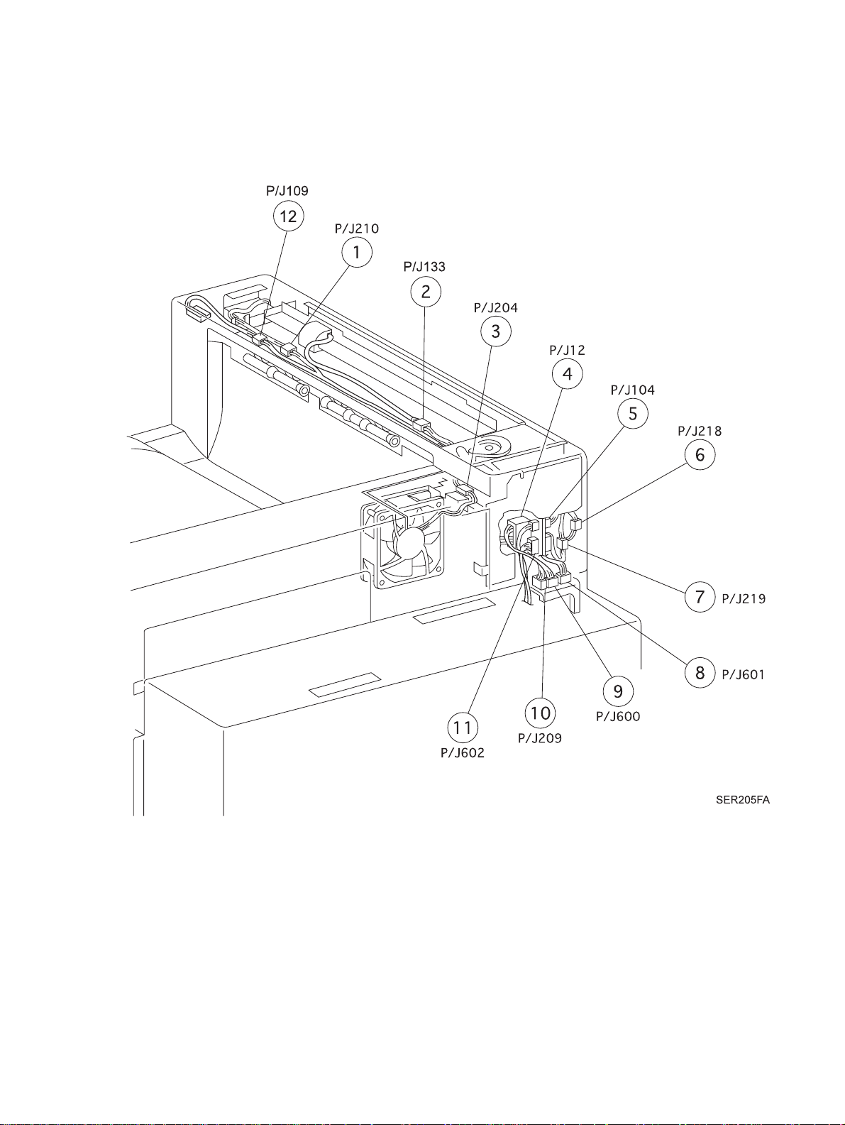
P/J Location Map 5. . . . . . . . . . . . . . . . . . . . . . . . . . . . . . . . . . . . . . . . . . . . . . . . . . . . . . . . . . . . .11-11
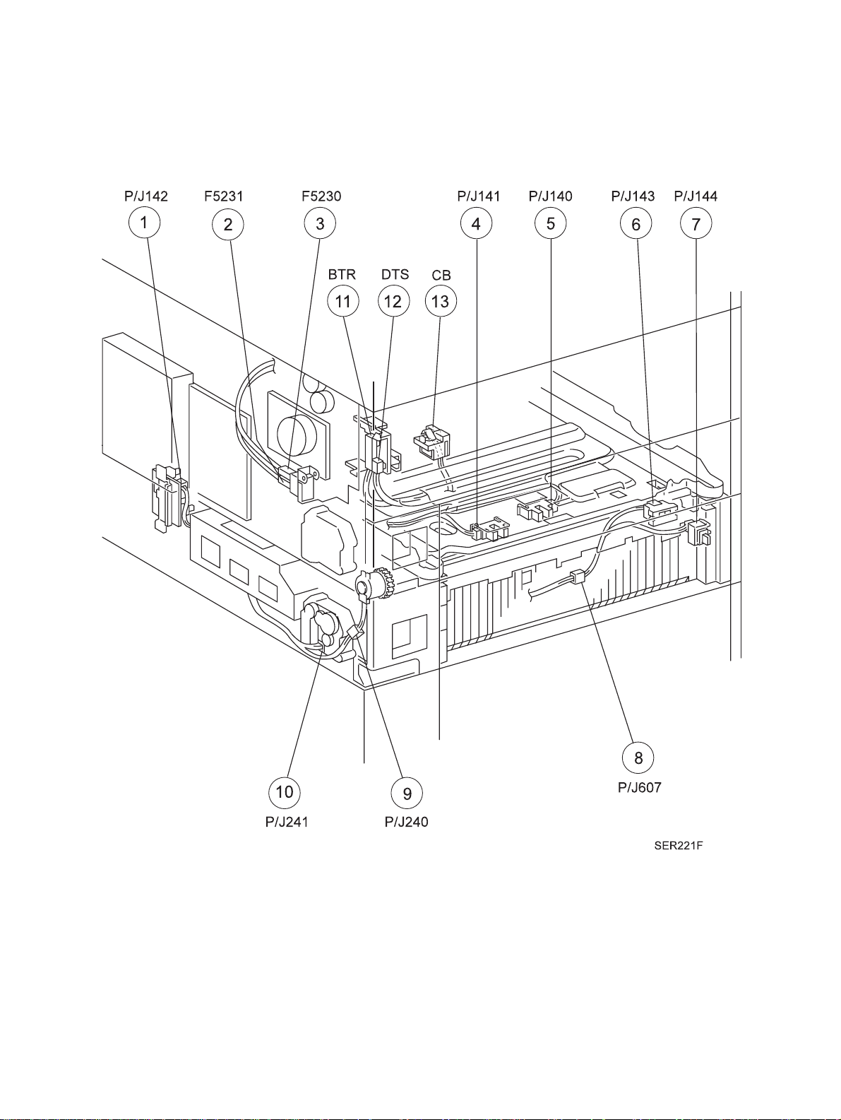
P/J Location Map 6. . . . . . . . . . . . . . . . . . . . . . . . . . . . . . . . . . . . . . . . . . . . . . . . . . . . . . . . . . . . .11-12
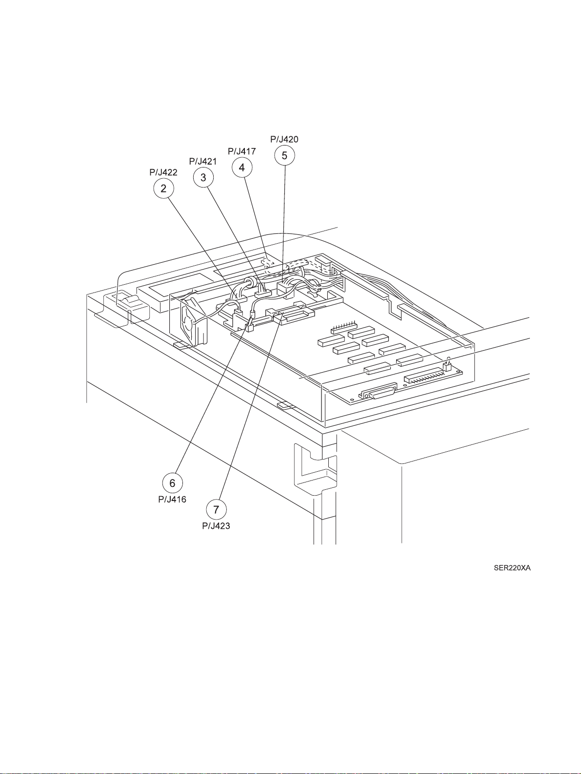
P/J Location Map 7. . . . . . . . . . . . . . . . . . . . . . . . . . . . . . . . . . . . . . . . . . . . . . . . . . . . . . . . . . . . .11-13
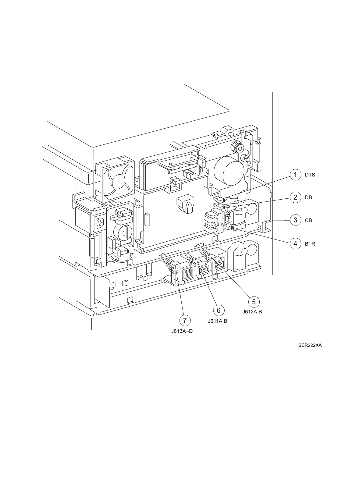
P/J Location Map 8. . . . . . . . . . . . . . . . . . . . . . . . . . . . . . . . . . . . . . . . . . . . . . . . . . . . . . . . . . . . .11-14
P/J Location Map 9. . . . . . . . . . . . . . . . . . . . . . . . . . . . . . . . . . . . . . . . . . . . . . . . . . . . . . . . . . . . .11-15
QMS 3260/4032 Laser Printer - Base Engine Technical Manual 11-1
Release Version 11-97

Locating P/J Connectors
Use the table and maps in this section to locate specific P/J connectors within the printer.
To find the location of a P/J:
1. Locate the P/J connector number in the first column of the table.
2. Locate the corresponding map and location number, such as M2-5, in the second column.
3. Go to the map (M2) number and locate item number (5).
P/J Location Table
P/J
1
12
13
19
20
23
100
101
102
103
104
105
Map &
Number
M2-7
M9-3
M5-4 Fuser Heat Rods & STS J23 AC Drive PWB & J600
M1-5 Finisher AC voltage connector CE11 & CE12 (110VAC line)
M9-11 Output - Noise Filter PWB F51/F53
M9-7 AC Drive PWB AC Hot and AC N
M9-9 AC Drive PWB P/J12 Fuser Heat Rods & STS
M3-5 Registration Sensor P/J459 MCU PWB
M3-7 Take Away Roll 1 Sensor P/J403 MCU PWB
M3-6 Tray 1 No Paper Sensor P/J459 MCU PWB
M3-4 Tray 1 Level Sensor P/J459 MCU PWB
M5-5 Fuser Exit Sensor P/J462 MCU PWB
M4-29 Tray 1 Paper Size Sensor P/J461 MCU PWB
LVPS (110VAC) Main Switch F52/F53
Connected to... Other end connected to...
106
107
108
109
127
133
140
141
11-2 QMS 3260/4032 Laser Printer - Base Engine Technical Manual
M1-1 SOS Sensor P/J456 MCU PWB
M3-1 MSI Size Sensor P/J403 MCU PWB
M3-8 MSI No Paper Sensor P/J403 MCU PWB
M5-12 Face Up Exit Sensor P/J462 MCU PWB
M4-11 MCU PWB Toner Sensor
M5-2 Full Stack Sensor P/J462 MCU PWB
M6-5 Tray 2 No Paper Sensor P/J408 MCU PWB
M6-4 Tray 2 Level Sensor P/J408 MCU PWB
Release Version 11-97

Locating P/J Connectors
P/J Location T able contin ued
P/J
142
143
144
200
201
202
203
204
205
207
208
209
Map &
Number
M6-1 Tray 2 Siz e Sensor P/J408 MCU PWB
M6-6 Take Away Roll Sensor P/J408 MCU PWB
M6-7 Tray 2 Left Cover Interlock Switch P/J607 and P/J408 MCU PWB
M4-13 Registration Clutch P/J462 MCU PWB
M4-18 Take Away Clutch P/J462 MCU PWB
M4-17 Feed Clutch 1 P/J462 MCU PWB
M4-19 Lift Up Motor 1 P/J403 MCU PWB
M5-3 Fuser Fan P/J460 MCU PWB
M4-10 Main Motor P/J460 MCU PWB
M1-6 Scanner Motor Assembly P/J456 MCU PWB
M3-2 MSI Feed Clutch P/J403 MCU PWB
M5-10 Offset Motor P/J462 MCU PWB
Connected to... Other end connected to...
210
218
219
232
233
234
235
240
241
400
401
402
M5-1 Exit Gate Solenoid P/J462 MCU PWB
M5-6 Inverter CW Clutch P/J462 MCU PWB
M5-7 Inverter CCW Clutch P/J462 MCU PWB
M4-32 Interlock Switch 2 P/J458 MCU PWB
M4-31 Interlock Switch 1 P/J458 MCU PWB
M4-6 CRU Switch 1 and CRU Switch 2 P/J407 Laser Diode Driver
P/J456 MCU PWB
M9-6 LVPS Fan P/J401 MCU PWB
M6-9 Tray 2 Feed Clutch P/J408 MCU PWB
M6-10 Tray 2 Lift Up Motor P/J408 MCU PWB
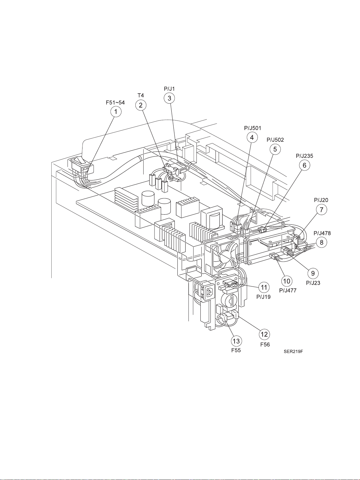
M4-3 MCU PWB P/J501 & P502 LVPS
M4-16 MCU PWB P/J477 AC Drive
P/J235 Fuser Fan
M4-27 MCU PWB P/J422 - ESS Mother PWB
QMS 3260/4032 Laser Printer - Base Engine Technical Manual 11-3
Release Version 11-97

Locating P/J Connectors
P/J Location Table continued
P/J
403
404
405
406
407
408
410
Map &
Number
M4-22 MCU PWB P/J107 MSI Size Sensor
M4-25 MCU PWB P/J611 Duplex Module
M4-23 MCU PWB P/J612 Mailbox or P612 Finisher
M4-24 MCU PWB P/J480/P/J481 HCF Cabinet PWB
M1-2 Laser Diode Driver P/J456 MCU PWB
M4-26 MCU PWB P/J140 No Paper Sensor 2
M4-28 MCU PWB Type D0 Console
Connected to... Other end connected to...
P/J108 MSI No Paper Sensor
P/J208 MSI Feed Clutch
P/J141 Level 2 Sensor
P/J142 Size 2 Paper Sensor
P/J143 Take Away Roll 2 Sensor
P/J144 Left Cover 2 Interlock Switch
P/J240 Tray 2 Feed Clutch
P/J241 Tray 2 Lift Up Motor
416
417
420
421
422
423
430
454
456
457
458
M7-6 ESS Mother PWB P/J430 Laser Diode Driver
M2-4
M7-4
M7-5 ESS Mother PWB P/J501/502 LV PS PWB
M7-3 ESS Mother PWB P/J417 Control Panel PWB
M7-2 ESS Mother PWB P/J402 MCU PWB
M7-7 QMS Video Controller ESS Mother PWB
M1-3 Laser Diode Driver ESS Mother PWB
M4-7 MCU PWB P/J606 CRU - CRU Memory
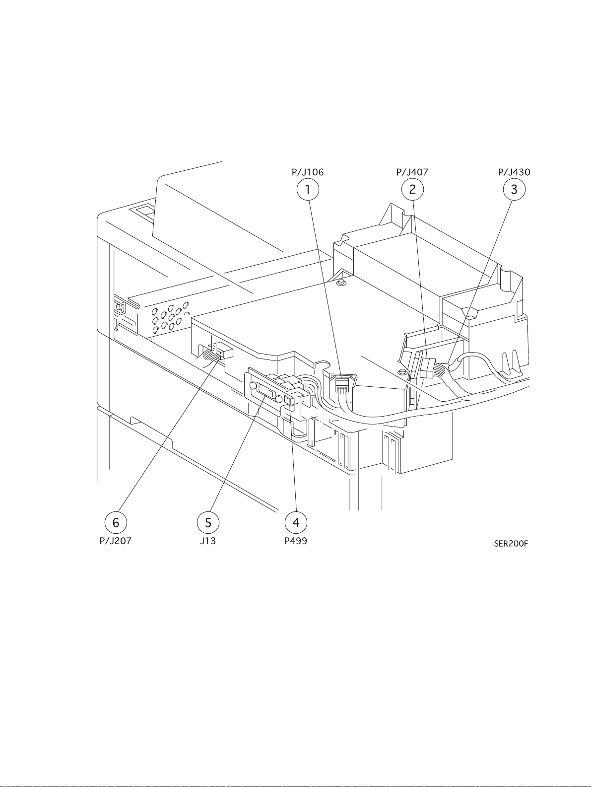
M4-2 MCU PWB P/J106 SOS Sen so r
M4-5 MCU PWB P/J500 HVPS
M4-4 MCU PWB P/J233 Interlocks SW1 and SW2
Control Panel P/J421 ESS Mother PWB
P/J207 ROS Motor
P/J234 CRU Interlock
P/J407 Laser Diode Driver
11-4 QMS 3260/4032 Laser Printer - Base Engine Technical Manual
Release Version 11-97

Locating P/J Connectors
P/J Location Table continued
P/J
459
460
461
462
477
478
Map &
Number
M4-21 MCU PWB P/J100 Registration Sensor
M4-9 MCU PWB P/J204 Fuser Fan
M4-20 MCU PWB P/J105 Size Sensor 1
M4-12 MCU PWB P/J202 Feed Clutch 1
M9-10 AC Drive PWB P/J401 MCU PWB
M9-8 AC Drive PWB Test output connector
Connected to... Other end connected to...
P/J102 No Paper 1 Sensor
P/J103 Level 1 Sensor
P/J205 Main Motor
P/J201 Take Away Roll 1 Clutch
P/J200 Registration Clutch
P/J104 Fuser Exit Sensor
P/J601 Face Up Exit Sensor
P/J601 Full Stack Sensor
P/J601 Exit Gate Solenoid
P/J218 Inverter CW Clutch
P/J219 Inverter CCW Clutch
499
500
501
502
600
601
602
603
604
606
M1-4 Test output connector P/J478 AC Drive PWB
M4-1 HVPS P/J457 MCU PWB
M2-2
M9-4
M2-17
M9-5
M5-9 Fuser STS P/J462 MCU PWB
M5-8 P109 Face Up Exit Sensor
M5-11 P218 Inverter CW Clutch
M3-9 P/J604 MSI P/J403 MCU PWB
M3-3 P107 MSI Size Sen so r
M4-8 CRU - CRU Memory P/J454 MCU PWB
LVPS P/J420 ESS Mother PWB
P/J400 MCU PWB
LVPS P/J420 ESS Mother PWB
P/J400 MCU PWB
P/J462 MCU PWB
P133 Full Stack Sensor
P210 Exit Gate Solenoid
P/J642 MCU PWB
P219 Inverter CCW Clutch
P/J403 MCU PWB
J108 MSI No Paper Sensor
P200 MSI Feed Clutch
QMS 3260/4032 Laser Printer - Base Engine Technical Manual 11-5
Release Version 11-97

Locating P/J Connectors
P/J Location Table continued
P/J
607
611
A,B
612
A,B
613
A~D
F51~
54
F55
F56
F
5230
Map &
Number
M6-8 P/J143 Take Away Roll Sensor
P/J144 Tray 2 Left Cover Interlock
Switch
M8-6 P/J473 Duplex PWB P/J404 MCU PWB
M8-5 P/J800 Ma ilbox PWB
P/J830 Fin isher PWB
M8-7 P/J406 MCU PWB P/J480 Finisher PWB
M9-1 Main Power Switch P/J19 Noise Filter PWB
M9-13 Noise Filter PWB AC Power Cord Hot
M9-12 Noise Filter PWB AC Power Cord Neutral
M4-14
M6-3
Main Interlock Switch P/J458 MCU PWB
Connected to... Other end connected to...
P/J408 MCU PWB
P/J405 MCU PWB
P/J481 Finisher PWB
P/J20 AC Drive PWB
P/J1 LVPS PWB
F
5231
BTR
CB
DTS
DB
T4
M4-15
M6-2
M6-11
M8-4
M6-13
M8-3
M6-12
M8-1
M8-2 Magnet Roll HVPS
M9-2 Frame Ground P/J1 LVPS PWB
Main Interlock Switch P/J458 MCU PWB
Bias Transfer Roll HVPS
Charge Roll HVPS
Detack Saw HVPS
11-6 QMS 3260/4032 Laser Printer - Base Engine Technical Manual
Release Version 11-97
Locating P/J Connectors
P/J Location Map 1
SER200F
QMS 3260/4032 Laser Printer - Base Engine Technical Manual 11-7
Release Version 11-97
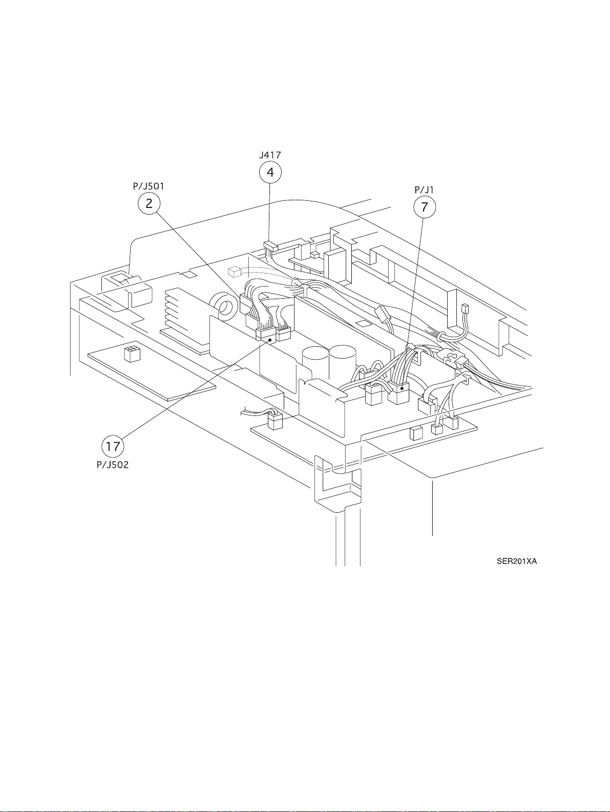
Locating P/J Connectors
P/J Location Map 2
SER201XA
11-8 QMS 3260/4032 Laser Printer - Base Engine Technical Manual
Release Version 11-97
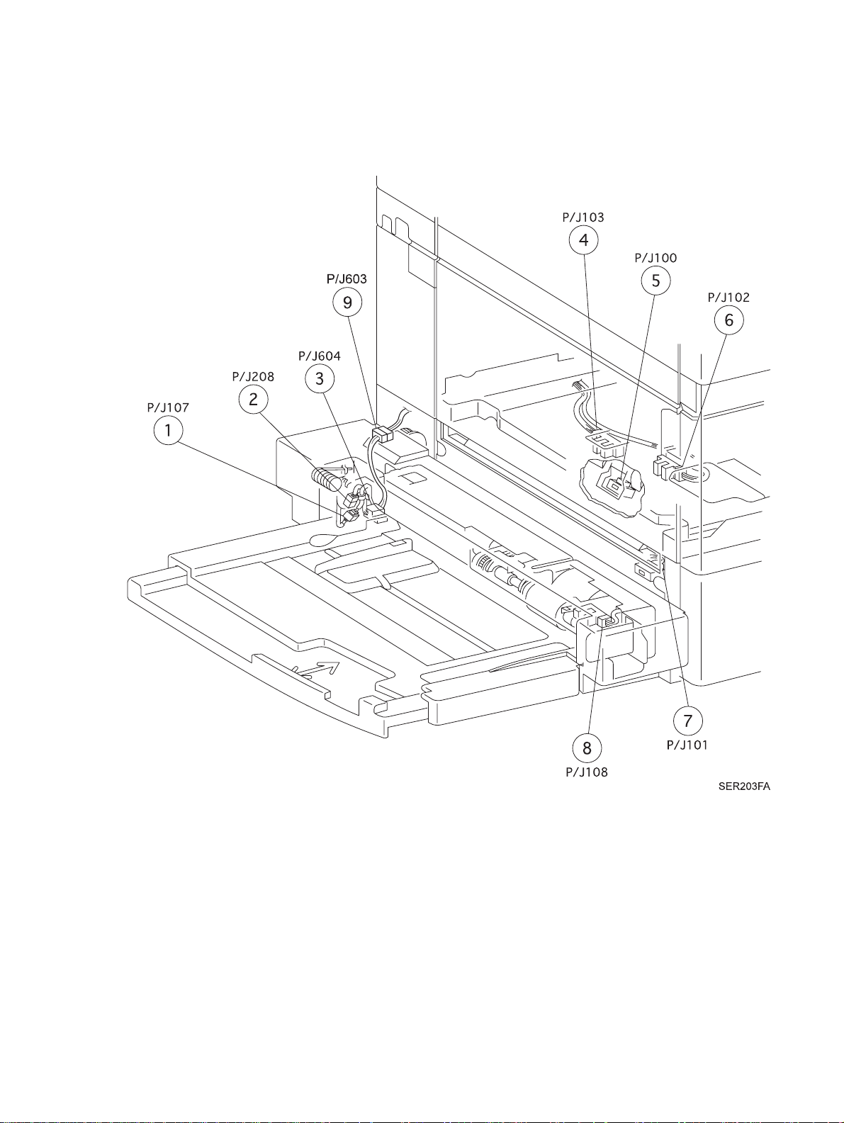
Locating P/J Connectors
P/J Location Map 3
SER203FA
QMS 3260/4032 Laser Printer - Base Engine Technical Manual 11-9
Release Version 11-97
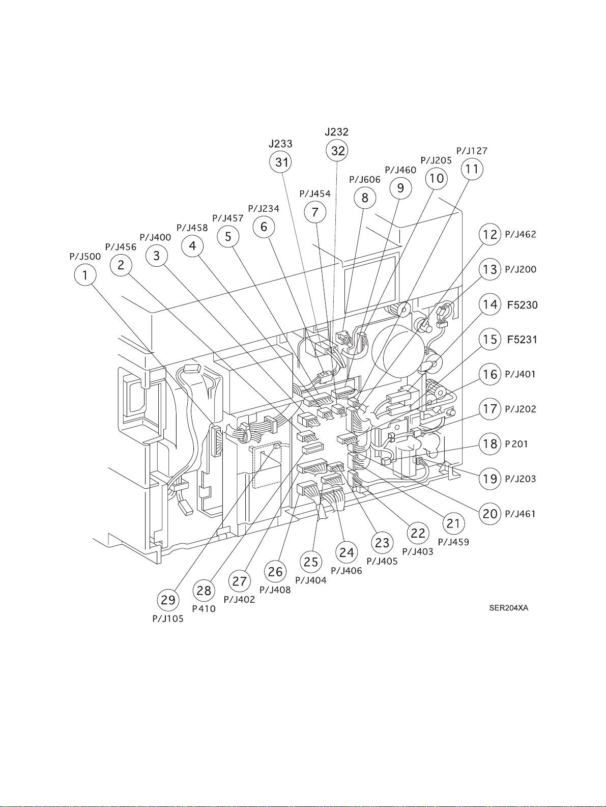
Locating P/J Connectors
P/J Location Map 4
SER204XA
11-10 QMS 3260/4032 Laser Printer - Base Engine Technical Manual
Release Version 11-97
Locating P/J Connectors
P/J Location Map 5
SER205FA
QMS 3260/4032 Laser Printer - Base Engine Technical Manual 11-11
Release Version 11-97
Locating P/J Connectors
P/J Location Map 6
SER221F
11-12 QMS 3260/4032 Laser Printer - Base Engine Technical Manual
Release Version 11-97
Locating P/J Connectors
P/J Location Map 7
SER220XA
QMS 3260/4032 Laser Printer - Base Engine Technical Manual 11-13
Release Version 11-97
Locating P/J Connectors
P/J Location Map 8
SER222XA
11-14 QMS 3260/4032 Laser Printer - Base Engine Technical Manual
Release Version 11-97
Locating P/J Connectors
P/J Location Map 9
SER219F
QMS 3260/4032 Laser Printer - Base Engine Technical Manual 11-15
Release Version 11-97

Locating P/J Connectors
Blank Page
11-16 QMS 3260/4032 Laser Printer - Base Engine Technical Manual
Release Version 11-97

Parts List
Section 12 - Parts List Contents
PL1.1 Top Cover Assembly . . . . . . . . . . . . . . . . . . . . . . . . . . . . . . . . . . . . . . . . . . . . . . . . . . . . . .12-4
PL1.2 Front Cover . . . . . . . . . . . . . . . . . . . . . . . . . . . . . . . . . . . . . . . . . . . . . . . . . . . . . . . . . . . . . 12-6
PL1.3 Rear, Left, and Right Covers . . . . . . . . . . . . . . . . . . . . . . . . . . . . . . . . . . . . . . . . . . . . . . . .12-8
PL2.1 Tray Unit - Paper Stack . . . . . . . . . . . . . . . . . . . . . . . . . . . . . . . . . . . . . . . . . . . . . . . . . . . 12-10
PL2.2 Tray Unit - End Guide . . . . . . . . . . . . . . . . . . . . . . . . . . . . . . . . . . . . . . . . . . . . . . . . . . . . 12-12
PL3.1 Tray Interface - Tray 1 . . . . . . . . . . . . . . . . . . . . . . . . . . . . . . . . . . . . . . . . . . . . . . . . . . . .12-14
PL3.2 Paper Pick Up - Tray 1. . . . . . . . . . . . . . . . . . . . . . . . . . . . . . . . . . . . . . . . . . . . . . . . . . . .12-16
PL3.3 Retard and Take Away - Tray 1 . . . . . . . . . . . . . . . . . . . . . . . . . . . . . . . . . . . . . . . . . . . . .12-18
PL3.4 Tray Interface - Tray 2 . . . . . . . . . . . . . . . . . . . . . . . . . . . . . . . . . . . . . . . . . . . . . . . . . . . .12-20
PL3.5 Paper Pick Up - Tray 2. . . . . . . . . . . . . . . . . . . . . . . . . . . . . . . . . . . . . . . . . . . . . . . . . . . .12-22
PL3.6 Retard and Take Away - Tray 2 . . . . . . . . . . . . . . . . . . . . . . . . . . . . . . . . . . . . . . . . . . . . .12-24
PL3.7 Feed Drive Transmission . . . . . . . . . . . . . . . . . . . . . . . . . . . . . . . . . . . . . . . . . . . . . . . . . . 12-26
PL4.1 Multi Sheet Inserter and MSI/Duplex Support . . . . . . . . . . . . . . . . . . . . . . . . . . . . . . . . . . 12-28
PL4.2 MSI Feeder Assembly . . . . . . . . . . . . . . . . . . . . . . . . . . . . . . . . . . . . . . . . . . . . . . . . . . . .12-30
PL4.3 Upper Feeder Assembly . . . . . . . . . . . . . . . . . . . . . . . . . . . . . . . . . . . . . . . . . . . . . . . . . . 12-32
PL4.4 MSI Tray Assembly . . . . . . . . . . . . . . . . . . . . . . . . . . . . . . . . . . . . . . . . . . . . . . . . . . . . . .12-34
PL5.1 Tray 1 Frame and Left Cover . . . . . . . . . . . . . . . . . . . . . . . . . . . . . . . . . . . . . . . . . . . . . . .12-36
PL5.2 Tray 2 Frame and Left Cover . . . . . . . . . . . . . . . . . . . . . . . . . . . . . . . . . . . . . . . . . . . . . . .12-38
PL6.1 Registration . . . . . . . . . . . . . . . . . . . . . . . . . . . . . . . . . . . . . . . . . . . . . . . . . . . . . . . . . . . . 12-40
PL6.2 Left Upper Cover Assembly. . . . . . . . . . . . . . . . . . . . . . . . . . . . . . . . . . . . . . . . . . . . . . . .12-42
PL6.3 Transport Chute Assembly . . . . . . . . . . . . . . . . . . . . . . . . . . . . . . . . . . . . . . . . . . . . . . . . 12-44
PL7.1 ROS Assembly . . . . . . . . . . . . . . . . . . . . . . . . . . . . . . . . . . . . . . . . . . . . . . . . . . . . . . . . .12-46
PL7.2 Xerography and Development. . . . . . . . . . . . . . . . . . . . . . . . . . . . . . . . . . . . . . . . . . . . . . 12-48
PL8.1 Fuser Assembly. . . . . . . . . . . . . . . . . . . . . . . . . . . . . . . . . . . . . . . . . . . . . . . . . . . . . . . . .12-50
PL9.1 Exit Lower Chute . . . . . . . . . . . . . . . . . . . . . . . . . . . . . . . . . . . . . . . . . . . . . . . . . . . . . . . . 12-52
PL9.2 Offset Roller. . . . . . . . . . . . . . . . . . . . . . . . . . . . . . . . . . . . . . . . . . . . . . . . . . . . . . . . . . . . 12-54
PL9.3 Exit Upper Chute Assembly. . . . . . . . . . . . . . . . . . . . . . . . . . . . . . . . . . . . . . . . . . . . . . . .12-56
PL9.4 Exit Drive Assembly. . . . . . . . . . . . . . . . . . . . . . . . . . . . . . . . . . . . . . . . . . . . . . . . . . . . . .12-58
PL10.1 Main Drive Assembly. . . . . . . . . . . . . . . . . . . . . . . . . . . . . . . . . . . . . . . . . . . . . . . . . . . . .12-60
PL10.2 Fuser Drive Assembly . . . . . . . . . . . . . . . . . . . . . . . . . . . . . . . . . . . . . . . . . . . . . . . . . . . . 12-62
PL11.1 Power Inlet and LVPS . . . . . . . . . . . . . . . . . . . . . . . . . . . . . . . . . . . . . . . . . . . . . . . . . . . .12-64
PL11.2 HVPS and MCU PWB . . . . . . . . . . . . . . . . . . . . . . . . . . . . . . . . . . . . . . . . . . . . . . . . . . . .12-66
PL11.3 ESS Assembly. . . . . . . . . . . . . . . . . . . . . . . . . . . . . . . . . . . . . . . . . . . . . . . . . . . . . . . . . .12-68
PL11.4 Harness . . . . . . . . . . . . . . . . . . . . . . . . . . . . . . . . . . . . . . . . . . . . . . . . . . . . . . . . . . . . . . . 12-70
QMS 3260/4032 Laser Printer - Base Engine Technical Manual 12-1
Release Version 11-97

Parts List
Section 12 - Parts List
Using the Parts List
1. The numbers shown in each illustration correspond to the parts list number for that illustration.
2. Throughout this manual, parts are ide ntifie d by the prefix “P L”, followed by a number, a decimal point,
and another number. For example, PL3.12 means the part is item 12 of parts list 3.
3. The capital letters “C”, “E”, "KL", and “S” shown in an illustra tion stand for C-ring, E-ri ng, Clamp, and
Screw, respectively.
4. A shaded triangle ▼ in an illustration indicates the item is part of an assembly .
5. The notation “
X through Y. For example, “1 (with 2~4)” means part 1 consists of part 2, part 3, and part 4.
6. The symbol
stocked and readily available. Other par ts may be stocked according t o the needs of ea ch individual
OEM client.
7. An asterisk
8. The notation “
attached to one end of the wire har ness and connector jack 2 is attached to the other end that is
plugged into plug 2.
9. An RRP number appears at the end of a par t line if the technical manual contains a removal and
replacement procedure for that part or module.
with X~Y
following a part name in dicate s the pa rt is an FX Recom mended Par t and is constan tly
$
following a part name indicates the page contains a note about this part.
*
J1<>J2 and P2
” following an part name indicates an assembly that is made up of components
” is attached to a wire harness. It indicates that connector jack 1 is
12-2 QMS 3260/4032 Laser Printer - Base Engine Technical Manual
Release Version 11-97

Parts List
Blank Page
QMS 3260/4032 Laser Printer - Base Engine Technical Manual 12-3
Release Version 11-97
Parts List
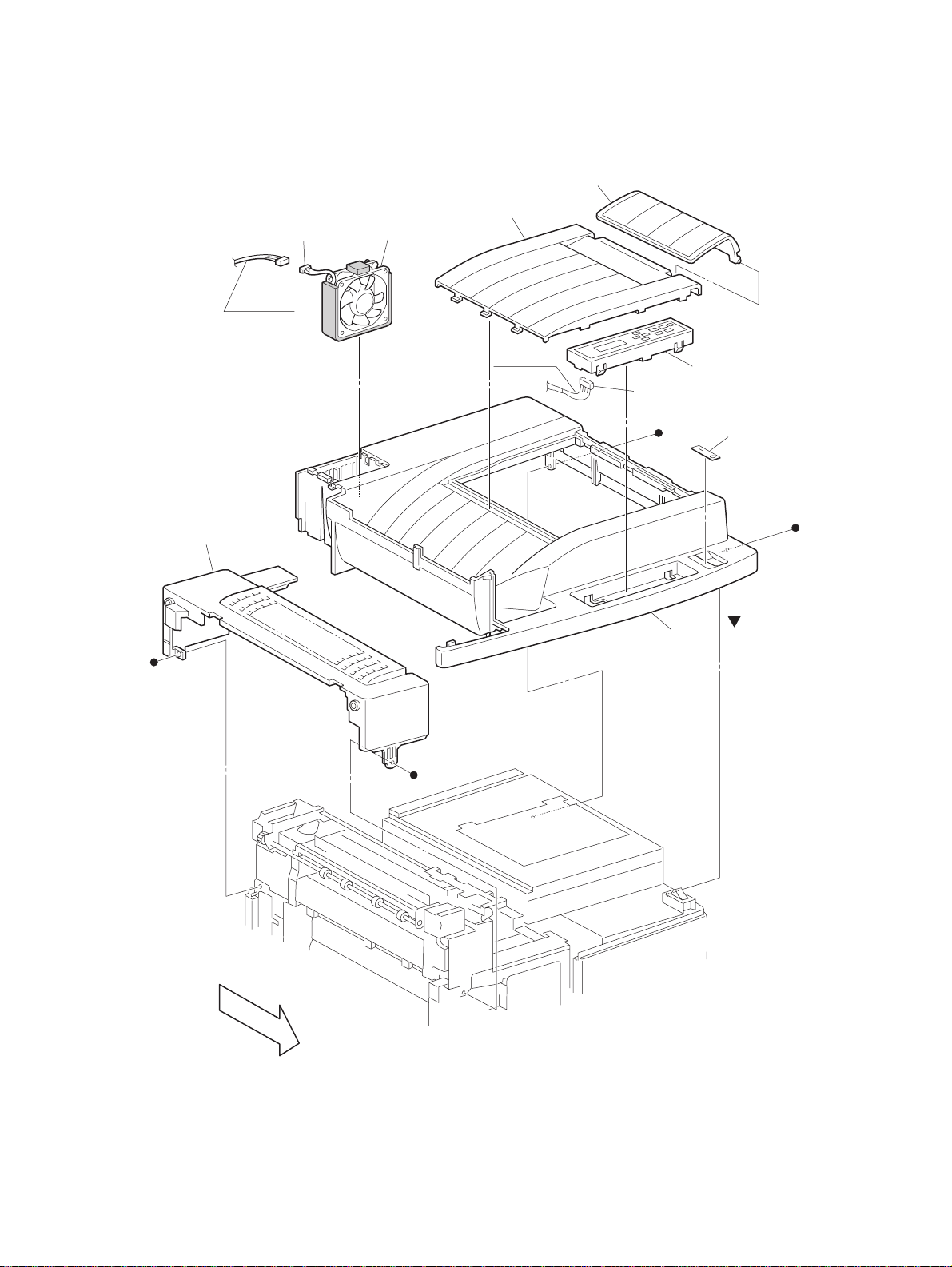
PL1.1 Top Cover Assembly
(J204)
PL11.4.23
7
6
8
PL11.3.16
(J417)
9
s
s
4
s
2
3
s
1 (with 2,3)
FRONT
SER501FC
SER501FC
12-4 QMS 3260/4032 Laser Printer - Base Engine Technical Manual
Release Version 11-97

1. COVER ASSEMBLY (with 2 and 3)
2. TOP COVER
3. LABEL SWITCH
4. CONSOLE PANEL
5. - -
6. COVER ESS
7. STOPPER
8. FAN ASSEMBLY FUSER
9. COVER-FUSER FULL
Parts List
PL1.1 Top Cover Assembly
QMS 3260/4032 Laser Printer - Base Engine Technical Manual 12-5
Release Version 11-97
Parts List
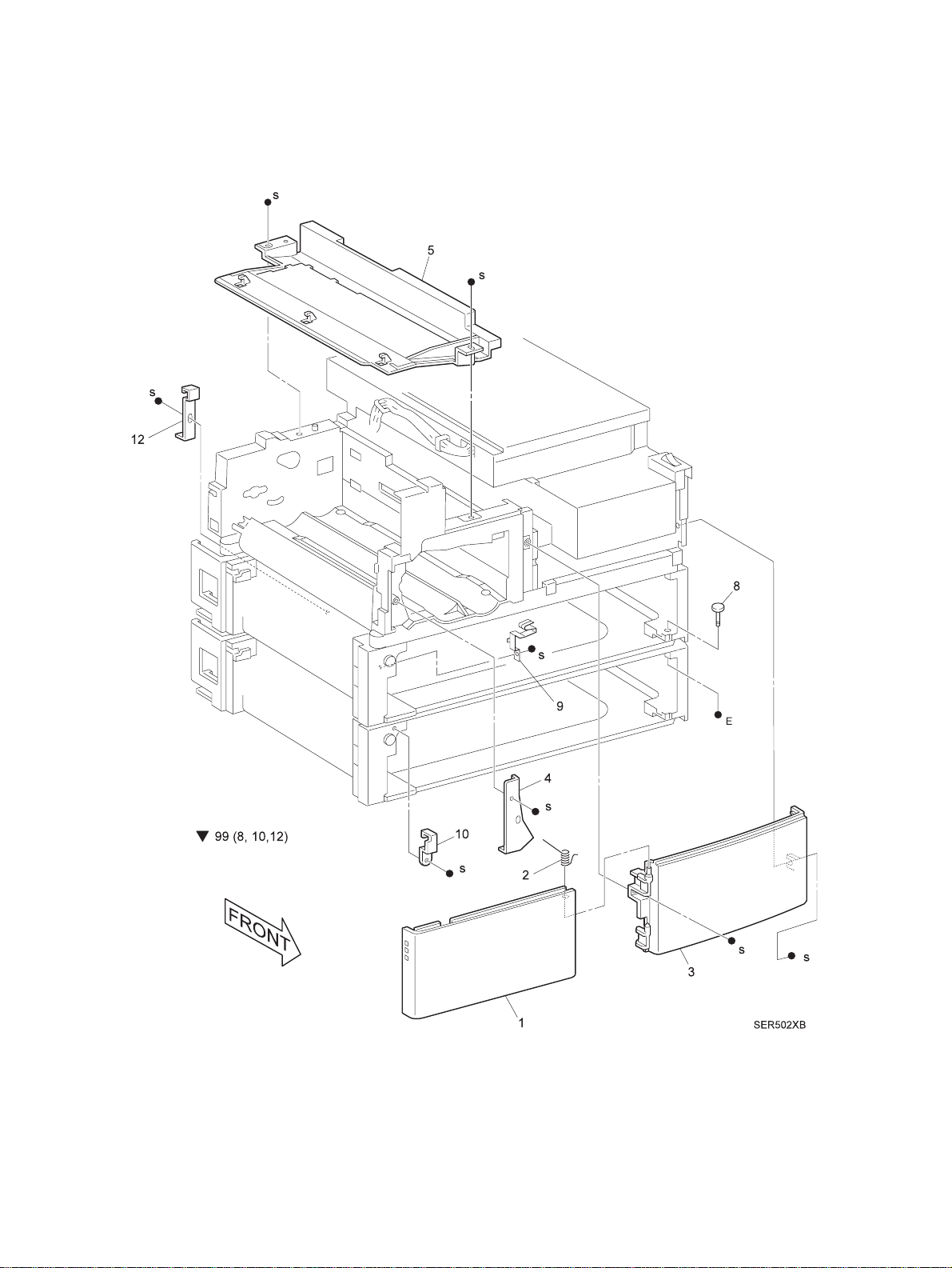
PL1.2 Front Cover
SER502XB
12-6 QMS 3260/4032 Laser Printer - Base Engine Technical Manual
Release Version 11-97

1. COVER ASSEMBLY FL
2. SPRING TORSION
3. COVER F/R
4. PLATE MAGNET
5. DUCT BOTTOM
6. - -
7. - -
8. STUD DOCKING
9. SPRING EME FRONT
10. BRACKET DOCKING LEFT
11. - -
12. BRACKET DOCKING REAR
99. KIT TRAY 2 MOUNTING (8, 10, 12)
Parts List
PL1.2 Front Cover
QMS 3260/4032 Laser Printer - Base Engine Technical Manual 12-7
Release Version 11-97
Parts List
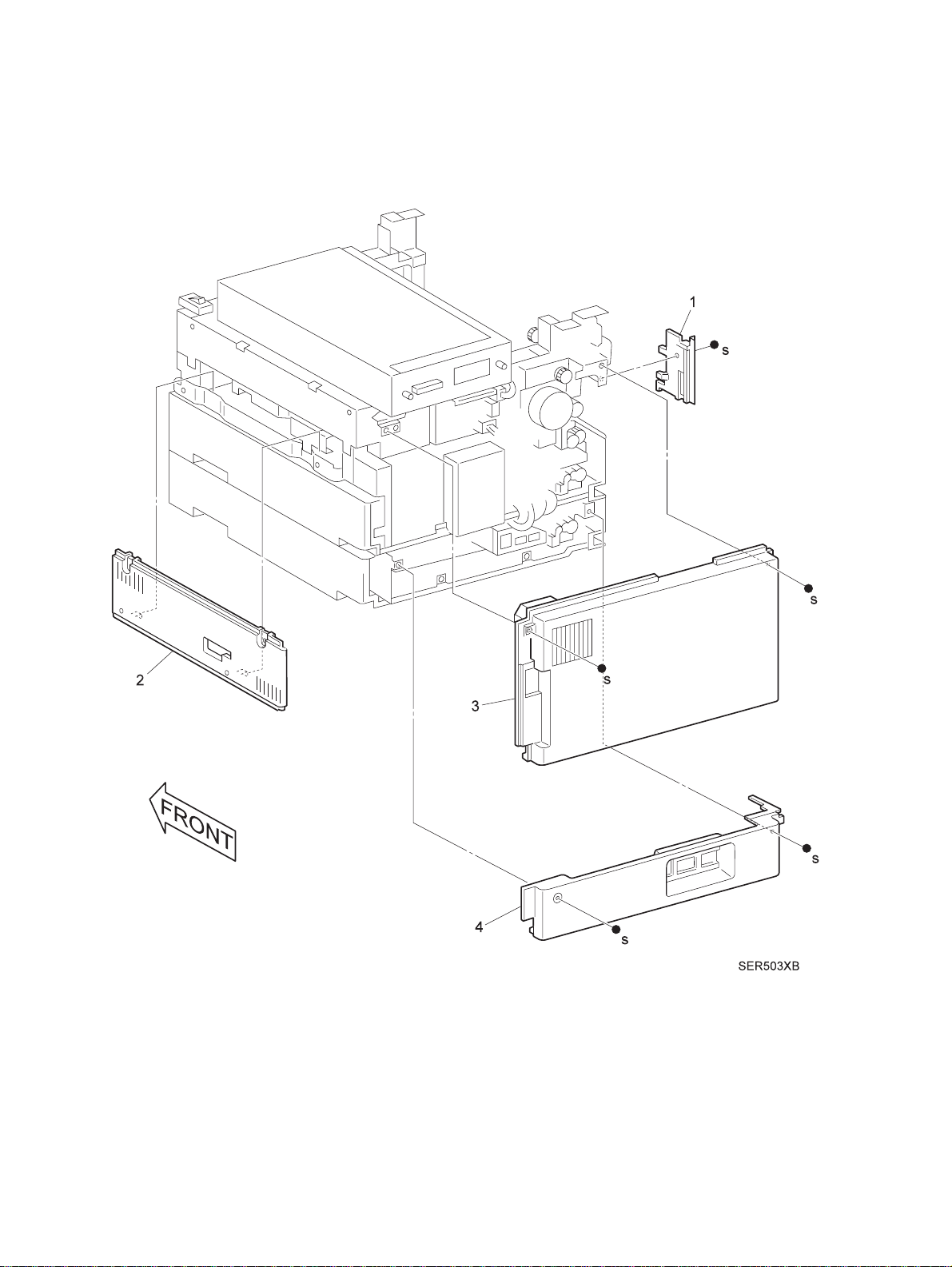
PL1.3 Rear, Left, and Right Covers
SER503XB
12-8 QMS 3260/4032 Laser Printer - Base Engine Technical Manual
Release Version 11-97

1. COVER INNER, LH
2. COVER RH
3. COVER ASSEMBLY, REAR OEM
4. COVER REAR 1TM, OEM
Parts List
PL1.3 Rear , Left, and Right Covers
QMS 3260/4032 Laser Printer - Base Engine Technical Manual 12-9
Release Version 11-97
Parts List
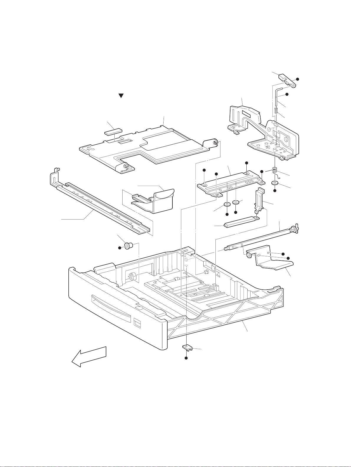
PL2.1 Tray Unit - Paper Stack
PL2.2.2
8
E
11
7
E
9
10
s
s
1 (with2~18,PL2.2)
2
3
s
s
14
PL2.2.1
18
17
E
12
17
s
s
5
13
6
SER504FB
FRONT
E
s
s
4
16
15
SER504FB
s
12-10 QMS 3260/4032 Laser Printer - Base Engine Technical Manual
Release Version 11-97

1. TRAY ASSEMBLY (with 2 ~ 18 and PL2.2)
2. PLATE BOTTOM
3. PAD BOTTOM
4. PLATE TONGUE
5. SHAFT ASSEMBLY - TONGUE
6. BEARING
7. GUIDE ASSEMBLY - SIDE
8. LEVER
9. SHAFT
10. SPRING - COMP
11. PLATE SIDE
12. ACTUATOR
13. LINK
14. SPRING - TORSION
Parts List
PL2.1 Tray Unit - Paper Stack
15. STOPPER L/H
16. HOUSING - TRAY
17. WASHER
18. WASHER - SIDE GUI DE
QMS 3260/4032 Laser Printer - Base Engine Technical Manual 12-11
Release Version 11-97
Parts List
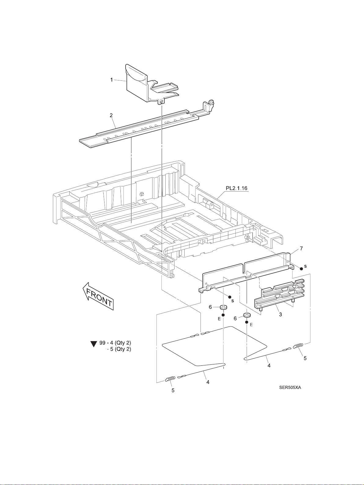
PL2.2 Tray Unit - End Guide
SER505XA
12-12 QMS 3260/4032 Laser Printer - Base Engine Technical Manual
Release Version 11-97

1. GUIDE ASSEMBLY - END
2. PLATE ASSEMBLY - END
3. ACTUATOR ASSEMBLY
4. CABLE ASSEMBLY
5. SPRING - EXTENSION
6. PULLEY
7. GUIDE A CTUATOR
99. KIT CASSETTE CABLES (with 4 (Qty 2) and 5 (Qty 2)
Parts List
PL2.2 Tray Unit - End Guide
QMS 3260/4032 Laser Printer - Base Engine Technical Manual 12-13
Release Version 11-97
Parts List
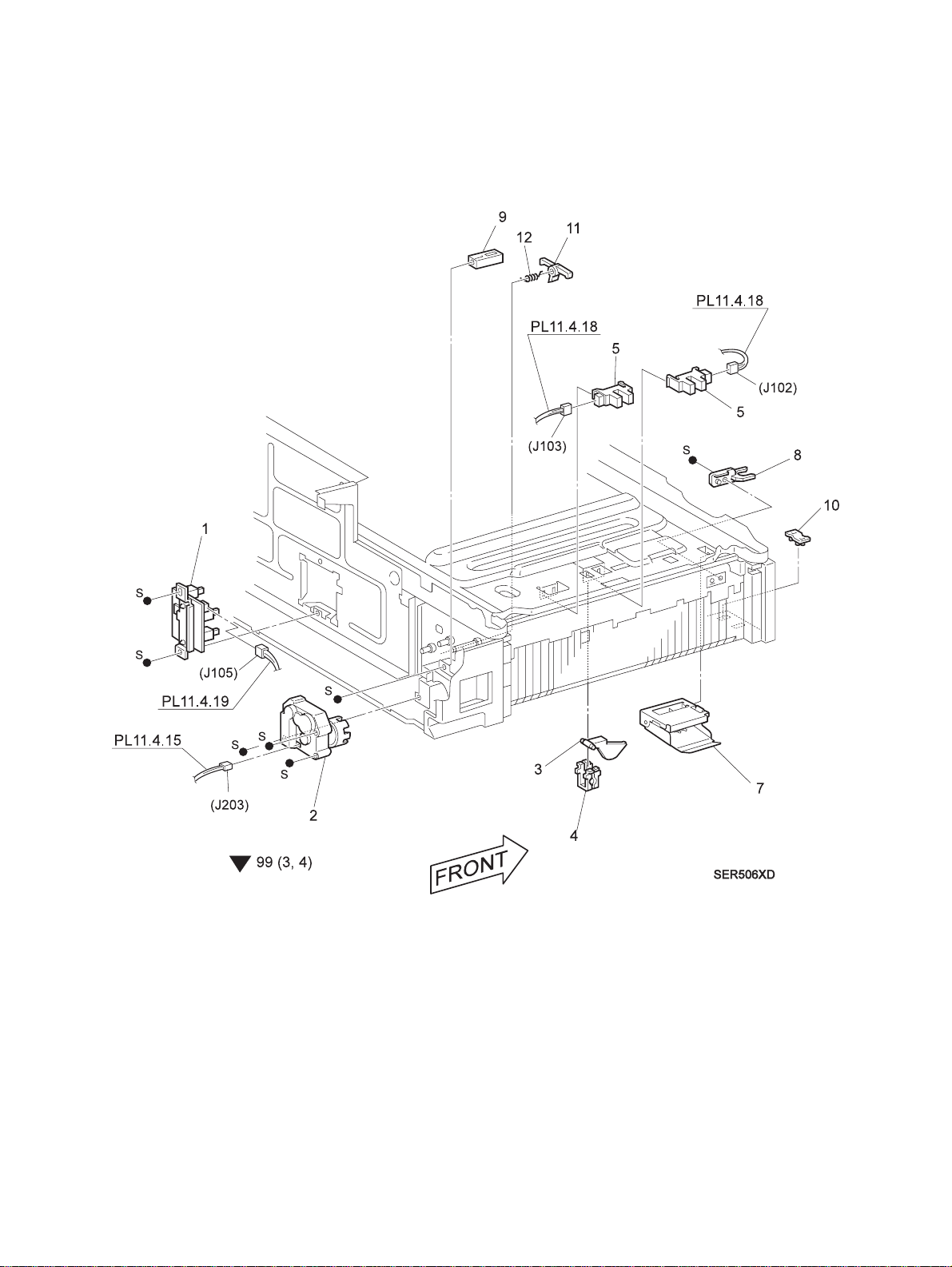
PL3.1 Tray Interface - Tray 1
SER506XD
12-14 QMS 3260/4032 Laser Printer - Base Engine Technical Manual
Release Version 11-97
 Loading...