

KONICA MINOLTA 2300 DL User Manual

1750068-001B

Trademarks
KONICA MINOLTA and the KONICA MINOLTA logo are trademarks or registered
trademarks of KONICA MINOLTA HOLDINGS, INC.
QCOLOR and magicolor are trademarks or registered trademarks of KONICA
MINOLTA PRINTING SOLUTIONS U.S.A., INC.
Proprietary Statement
The digitally encoded software included with your printer is Copyright © 2004
KONICA MINOLTA BUSINESS TECHNOLOGIES, INC. All Rights Reserved. This
software may not be reproduced, modified, displayed, transferred, or copied in
any form or in any manner or on any media, in whole or in part, without the
express written permission of KONICA MINOLTA BUSINESS TECHNOLOGIES,
INC.
Copyright Notice
Copyright © 2004 KONICA MINOLTA BUSINESS TECHNOLOGIES, INC.,
Marunouchi Center Building, 1-6-1 Marunouchi, Chiyoda-ku, Tokyo, 100-0005,
Japan. All Rights Reserved. This document may not be copied, in whole or part,
nor transferred to any other media or language, without written permission of
KONICA MINOLTA BUSINESS TECHNOLOGIES, INC.
Manual Notice
KONICA MINOLTA BUSINESS TECHNOLOGIES, INC. reserves the right to make
changes to this manual and to the equipment described herein without notice.
Considerable effort has been made to ensure that this manual is free of
inaccuracies and omissions. However, KONICA MINOLTA BUSINESS
TECHNOLOGIES, INC. makes no warranty of any kind including, but not limited
to, any implied warranties of merchantability and fitness for a particular purpose
with regard to this manual. KONICA MINOLTA BUSINESS TECHNOLOGIES, INC.
assumes no responsibility for, or liability for, errors contained in this manual or for
incidental, special, or consequential damages arising out of the furnishing of this
manual, or the use of this manual in operating the equipment, or in connection
with the performance of the equipment when so operated.
2

CONTENTS
3


CONTENTS .................................................................3
SAFETY .......................................................................9
Safety Precautions for Inspection and Service .................................................. 11
Warning ....................................................................................................... 11
Caution ........................................................................................................ 13
Used Batteries Precautions .........................................................................15
Other Precautions ........................................................................................ 16
Precautions for Service ................................................................................ 16
Safety information ........................................................................................ 19
Laser Safety Label ....................................................................................... 22
Laser Caution Label ..................................................................................... 22
PRECAUTIONS FOR HANDLING THE LASER EQUIPMENT ...................23
GENERAL ..................................................................25
Product Specifications ........................................................................................ 27
Installation Precautions ...................................................................................... 31
Installation environment ............................................................................... 31
Installation power supply ............................................................................. 31
Space requirements...................................................................................... 32
Operation Precautions .......................................................................................33
Ensuring the optimum performance of this unit ...........................................33
Operating environment ................................................................................33
Power supply requirements .........................................................................33
Other precautions ........................................................................................33
Parts Identification .......................................................................................34
MECHANICAL/ ELECTRICAL ...................................35
CROSS-SECTIONAL VIEW ............................................................................... 37
ELECTRICAL COMPONENTS LAYOUT ........................................................... 38
OPERATING SEQUENCE ................................................................................. 43
IMAGE STABILIZATION CONTROL .................................................................44
AIDC Detection ............................................................................................ 44
Outline of AIDC Control ...............................................................................45
Operation Timing .........................................................................................46
Temperature/Humidity Sensor ..................................................................... 47
ATVC (Auto Transfer Voltage Control ......................................................... 48
DRUM CARTRIDGE ..........................................................................................49
PC Drum ...................................................................................................... 49
PC Drum Charging ...................................................................................... 50
LASER EXPOSURE ..........................................................................................51
DEVELOPING UNIT ..........................................................................................53
Developing Position ..................................................................................... 55
Toner Cartridge ............................................................................................ 56
IMAGE TRANSFER ...........................................................................................60
Image Transfer Belt Unit .............................................................................. 60
Second Image Transfer Roller Cleaning ......................................................63
Image Transfer Belt Cleaning Mechanism................................................... 64
Waste Toner Bottle ...................................................................................... 66
5

Waste Toner Bottle Detection ..................................................................... 66
FUSING SECTION ............................................................................................ 67
Fusing Unit .................................................................................................. 67
Fusing Temperature Control ....................................................................... 69
PAPER TAKE-UP SECTION ............................................................................. 71
Manual Feed Tray ....................................................................................... 71
Lower Feeder Unit (Option) ......................................................................... 72
OTHER MECHANISMS ..................................................................................... 73
Duplex Unit (Option) .................................................................................... 73
MAINTENANCE & DISASSEMBLY/ASSEMBLY .......81
Disassembly/Assembly Precautions .................................................................. 83
Precautions for disassembly and assembly ................................................ 83
Parts that must not be touched ................................................................... 83
Precautions for transporting or storing PWBs ............................................. 83
Precautions for replacing PWBs .................................................................. 83
Precautions for inspecting PWBs ................................................................ 83
Precautions for transporting or storing the OPC drum cartridge ................. 84
Precautions for handling the OPC drum cartridge ....................................... 84
Red painted Screws .................................................................................... 84
Variable Resistors on Board ........................................................................ 84
Maintenance Schedule ...................................................................................... 85
Guideline for Life Specifications Values by Unit........................................... 87
Detail of Each Unit Life ................................................................................ 87
Maintenance And Cleaning ............................................................................... 89
Replacement of the Units .................................................................................. 93
Disassembly Procedures ............................................................................. 96
Pre-disassembly preparation ....................................................................... 98
Removal Of Circuit Boards And Other Electrical Components ................. 100
Removal of Units ....................................................................................... 106
DISASSEMBLY OF THE ENGINE PARTS ............................................... 111
CONTROL PANEL / SERVICE MODE DESCRIPT. 127
Control Panel Descriptions—2300DL & 2350 ................................................. 129
Names of control panel parts and their functions ...................................... 129
Message Window ...................................................................................... 129
Menu Contents for magicolor 2300 DL ............................................................ 133
Print menu overview .................................................................................. 133
Settings menus .......................................................................................... 134
Service Mode ............................................................................................ 136
Service mode displays .............................................................................. 136
Entering service mode .............................................................................. 136
Service mode options ................................................................................ 136
Menu Contents for magicolor 2350 ................................................................. 138
Menu Overview ......................................................................................... 138
About the 2300W Control Panel ...................................................................... 140
Control Panel Key ..................................................................................... 140
Indicator Lights .......................................................................................... 141
Working with the 2300W Status Display ................................................... 142
6

Using the Status Display ............................................................................ 143
Status, Error and Service Messages .........................................................144
TROUBLESHOOTING .............................................147
Introduction ...................................................................................................... 149
Checking the electrical components .......................................................... 149
Paper Misfeeds ................................................................................................ 152
Perform initial check procedures ............................................................... 152
Paper misfeed displays .............................................................................. 153
Wiring diagram of misfeed-detecting sensors ............................................ 154
Misfeed detection timing and remedies .....................................................155
Malfunctions and Warnings (2300 DL & 2350) ................................................159
Malfunction detection timing and remedies ............................................... 161
Power supply malfunctions ........................................................................ 167
Image Quality Troubleshooting ........................................................................ 168
INDEX ......................................................................171
7

8

SAFETY
9

1. SAFETY PRECAUTIONS FOR INSPECTION AND SERVICE
• When performing inspection and service procedures, observe the following precautions
to prevent accidents and ensure utmost safety.
✽ Depending on the model, some of the precautions listed below do not apply.
• Different markings are used to denote specific meanings as detailed below.
WARNING
• Indicates a potentially hazardous situation which, if not avoided, may result in minor or
moderate injury. It may also be used to alert against unsafe practices.
CAUTION
• Indicates a potentially hazardous situation whech, if not avoided, may result in minor or
moderate injury. It may also be used to alert against unsave practices.
• The following graphic symbols are used to give instructions that need to be observed.
Used to call the service technician attention to what is graphically represented
inside the marking (including a warning).
Used to prohibit the service technician from doing what is graphically represented
inside the marking.
Used to instruct the service technician to do what is graphically represented
inside the marking.
1-1. Warning
WARNING
1. Always observe precautions.
• Parts requiring special attention in this product include a label containing the
mark shown on the left plus precautionary notes. Be sure to observe the precautions.
• Be sure to observe the “Safety Information” given in the user documentation.
2. Before starting the procedures, be sure to unplug the power cord.
11
• This product contains a high-voltage unit and a circuit with a large current
capacity that may cause an electric shock or burn.
• The product also contains parts that can jerk suddenly and cause injury.
• If this product uses a laser, laser beam leakage may cause eye damage or
blindness.
WARNING
3. Do not throw toner or the toner bottle into a fire.
• Do not throw toner or the Toner Bottle (Imaging Cartridge, Toner Cartridge) into
a fire. Toner expelled from the fire may cause burns.
4. Use the specified parts.
• For replacement parts, always use the genuine parts specified in the manufacturer’s parts manual. Installing a wrong or unauthorized part could cause
dielectric breakdown, overload, or undermine safety devices resulting in possible electric shock or fire.
• Replace a blown electrical fuse or thermal fuse with its corresponding genuine
part specified in the manufacturer’s parts manual. Installing a fuse of a different
make or rating could lead to a possible fire. If a thermal fuse blows frequently,
the temperature control system may have a problem and action must be taken
to eliminate the cause of the problem.
5. Handle the power cord with care and never use a multiple outlet.
• Do not break, crush or otherwise damage the power cord. Placing a heavy
object on the power cord, or pulling or bending it may damage it, resulting in a
possible fire or electric shock.
• Do not use a multiple outlet to which any other appliance or machine is connected.
• Be sure the power outlet meets or exceeds the specified capacity.
6. Be careful with the high-voltage parts.
• A part marked with the symbol shown on the left carries a high voltage. Touching it could result in an electric shock or burn. Be sure to unplug the power cord
before servicing this part or the parts near it.
7. Do not work with wet hands.
• Do not unplug or plug in the power cord, or perform any kind of service or
inspection with wet hands. Doing so could result in an electric shock.
8. Do not touch a high-temperature part.
• A part marked with the symbol shown on the left and other parts such as the
exposure lamp and fusing roller can be very hot while the machine is energized. Touching them may result in a burn.
• Wait until these parts have cooled down before replacing them or any surrounding parts.
12
WARNING
9. Maintain a Grounded Connection at all times.
• Connect the power cord to an electrical outlet that is equipped with a grounding terminal.
10. Do not remodel the product.
• Modifying this product in a manner not authorized by the manufacturer may
result in a fire or electric shock. If this product uses a laser, laser beam leakage
may cause eye damage or blindness.
11. Restore all parts and harnesses to their original positions.
• To promote safety and prevent product damage, make sure the harnesses are
returned to their original positions and properly secured in their clamps and
saddles in order to avoid hot parts, high-voltage parts, sharp edges, or being
crushed.
• To promote safety, make sure that all tubing and other insulating materials are
returned to their original positions. Make sure that floating components
mounted on the circuit boards are at their correct distance and position off the
boards.
1-2. Caution
CAUTION
1. Precautions for Service Jobs.
• A star washer and spring washer, if used originally, must be reinstalled. Omitting them may result in contact failure which could cause an electric shock or
fire.
• When reassembling parts, make sure that the correct screws (size, type) are
used in the correct places. Using the wrong screw could lead to stripped
threads, poorly secured parts, poor insulating or grounding, and result in a malfunction, electric shock or injury.
• Take great care to avoid personal injury from possible burrs and sharp edges
on the parts, frames and chassis of the product.
• When moving the product or removing an option, use care not to injure your
back or allow your hands to be caught in mechanisms.
13
CAUTION
2. Precautions for Servicing with Covers and Parts Removed.
• Wherever feasible, keep all parts and covers mounted when energizing the
product.
• If energizing the product with a cover removed is absolutely unavoidable, do
not touch any exposed live parts and use care not to allow your clothing to be
caught in the moving parts. Never leave a product in this condition unattended.
• Never place disassembled parts or a container of liquid on the product. Parts
falling into, or the liquid spilling inside, the mechanism could result in an electric shock or fire.
• Never use a flammable spray near the product. This could result in a fire.
• Make sure the power cord is unplugged before removing or installing circuit
boards or plugging in or unplugging connectors.
• Always use the interlock switch actuating jig to actuate an interlock switch
when a cover is opened or removed. The use of folded paper or some other
object may damage the interlock switch mechanism, possibly resulting in an
electric shock, injury or blindness.
3. Precautions for the Working Environment.
• The product must be placed on a flat, level surface that is stable and secure.
• Never place this product or its parts on an unsteady or tilting workbench when
servicing.
• Provide good ventilation at regular intervals if a service job must be done in a
confined space for a long period of time.
• Avoid dusty locations and places exposed to oil or steam.
• Avoid working positions that may block the ventilation ports of the product.
4. Precautions for Handling Batteries. (Lithium, Nickel-Cadmium, etc.)
• Replace a rundown battery with the same type as specified in the manufacturer’s parts manual.
• Before installing a new battery, make sure of the correct polarity of the installation or the battery could burst.
• Dispose of used batteries according to the local regulations. Never dispose of
them at the user’s premises or attempt to try to discharge one.
5. Precautions for the Laser Beam. (Only for Products Employing a Laser)
• Removing the cover marked with the caution label could lead to possible exposure to the laser beam, resulting in eye damage or blindness. Be sure to
unplug the power cord before removing this cover.
• If removing this cover while the power is ON is unavoidable, be sure to wear
protective laser goggles that meet specifications.
• Make sure that no one enters the room when the machine is in this condition.
• When handling the laser unit, observe the “Precautions for Handling Laser
Equipment.”
6. Precautions for storing the toner or imaging cartridge.
• Be sure to keep the toner or imaging cartridge out of the reach of children.
Licking the imaging cartridge or ingesting its contents is harmful to your health.
14

1-3. Used Batteries Precautions
ALL Areas
Danger of explosion if battery is incorrectly replaced.
Replace only with the same or equivalent type recommended by the manufacturer.
Dispose of used batteries according to the manufacturer’s instructions.
Germany
Explosionsgefahr bei unsachgemäßem Austausch der Batterie.
Ersatz nur durch denselben oder einen vom Hersteller empfohlenen gleichwertigen Typ.
Entsorgung gebrauchter Batterien nach Angaben des Herstellers.
France
Il y a danger d’explosion s’il y a remplacement incorrect de la batterie.
Remplacer uniquement avec une batterie du même type ou d’un type équivalent recommandé par le constructeur.
Mettre au rebut les batteries usagées conformément aux instructions du fabricant.
Denmark
Lithiumbatteri - Eksplosionsfare ved fejlagtig håndtering.
Udskiftning må kun ske med batteri af samme fabrikat og type.
Levér det brugte batteri tilbage til leverandøren.
Finland, Sweden
Paristo voi räjähtää, jos se on virheellisesti asennettu.
Vaihda paristo ainoastaan laitevalmistajan suosittelemaan tyyppiin.
Hävitä käytetty paristo valmistajan ohjeiden mukaisesti.
CAUTION
VORSICHT!
ATT ENTI ON
ADVARSEL!
VAR OlTU S
Explosionsfara vid felaktigt batteribyte.
Använd samma batterityp eller en ekvivalent typ som rekommenderas av apparattillverkaren.
Kassera använt batteri enligt fabrikantens instruktion.
Norway
Eksplosjonsfare ved feilaktig skifte av batteri.
Benytt samme batteritype eller en tilsvarende type anbefalt av apparatfabrikanten.
Brukte batterier kasseres i henhold til fabrikantens instruksjoner.
VARNING
ADVARSEL
15

1-4. Other Precautions
• When handling circuit boards, observe the “HANDLING of PWBs”.
• The PC Drum is a very delicate component. Observe the precautions given in “HANDLING OF THE PC DRUM” because mishandling may result in serious image problems.
• Note that replacement of a circuit board may call for readjustments or resetting of particular items, or software installation.
1-5. Precautions for Service
• When performing inspection and service procedures, observe the following precautions
to prevent mishandling of the machine and its parts.
✽ Depending on the model, some of the precautions given in the following do not apply.
1. Precautions Before Service
• When the user is using a word processor or personal computer from a wall outlet of the
same line, take necessary steps to prevent the circuit breaker from opening due to overloads.
• Never disturb the LAN by breaking or making a network connection, altering termination,
installing or removing networking hardware or software, or shutting down networked
devices without the knowledge and express permission of the network administrator or
the shop supervisor.
2. How to Use this Book
DIS/REASSEMBLY, ADJUSTMENT
• To reassemble the product, reverse the order of disassembly unless otherwise specified.
TROUBLESHOOTING
• If a component on a PWB or any other functional unit including a motor is defective, the
text only instructs you to replace the whole PWB or functional unit and does not give troubleshooting procedures applicable within the defective unit.
• All troubleshooting procedures contained herein assume that there are no breaks in the
harnesses and cords and all connectors are plugged into the right positions.
• The procedures preclude possible malfunctions due to noise and other external causes.
3. Precautions for Service
• Keep all disassembled parts in good order and keep tools under control so that none will
be lost or damaged.
• After completing a service job, perform a safety check. Make sure that all parts, wiring
and screws are returned to their original positions.
• Do not pull out the toner hopper while the toner bottle is turning. This could result in a
damaged motor or locking mechanism.
• If the product is to be run with the front door open, make sure that the toner hopper is in
the locked position.
• Do not use an air gun or vacuum cleaner for cleaning the ATDC Sensor and other sensors, as they can cause electrostatic damage. Use a blower brush and cloth. If a unit
containing these sensors is to be cleaned, first remove the sensors from the unit.
16

4. Precautions for Dis/Reassembly
• Be sure to unplug the printer from the outlet before attempting to service the printer.
• The basic rule is not to operate the printer anytime during disassembly. If it is absolutely
necessary to run the printer with its covers removed, use care not to allow your clothing
to be caught in revolving parts such as the timing belt and gears.
• Before attempting to replace parts and unplug connectors, make sure that the power
cord of the printer has been unplugged from the wall outlet.
• Be sure to use the Interlock Switch Actuating Jig whenever it is necessary to actuate the
Interlock Switch with the covers left open or removed.
• While the product is energized, do not unplug or plug connectors into the circuit boards
or harnesses.
• Never use flammable sprays near the printer.
• A used battery should be disposed of according to the local regulations and never be discarded casually or left unattended at the user’s premises.
• When reassembling parts, make sure that the correct screws (size, type) and toothed
washer are used in the correct places.
5. Precautions for Circuit Inspection
• Never create a closed circuit across connector pins except those specified in the text and
on the printed circuit.
• When creating a closed circuit and measuring a voltage across connector pins specified
in the text, be sure to use the GND wire.
6. Handling of PWBs
During Transportation/Storage
• During transportation or when in storage, new P.W. Boards must not be indiscriminately
removed from their protective conductive bags.
• Do not store or place P.W. Boards in a location exposed to direct sunlight and high temperature.
• When it becomes absolutely necessary to remove a Board from its conductive bag or
case, always place it on its conductive mat in an area as free as possible from static electricity.
• Do not touch the pins of the ICs with your bare hands.
• Protect the PWBs from any external force so that they are not bent or damaged.
During Inspection/Replacement
• Avoid checking the IC directly with a multimeter; use connectors on the Board.
• Never create a closed circuit across IC pins with a metal tool.
• Before unplugging connectors from the P.W. Boards, make sure that the power cord has
been unplugged from the outlet.
• When removing a Board from its conductive bag or conductive case, do not touch the
pins of the ICs or the printed pattern. Place it in position by holding only the edges of the
Board.
• When touching the PWB, wear a wrist strap and connect its cord to a securely grounded
place whenever possible. If you cannot wear a wrist strap, touch a metal part to discharge static electricity before touching the PWB.
• Note that replacement of a PWB may call for readjustments or resetting of particular
items.
7. Handling of Other Parts
• The magnet roller generates a strong magnetic field. Do not bring it near a watch, floppy
disk, magnetic card, or CRT.
17

8. Handling of the Imaging Cartridge
During Transportation/Storage
• The storage temperature is in the range between –20 °C and +40 °C.
• In summer, avoid leaving the Imaging Cartridge in a car for a long time.
Handling
• Store the Imaging Cartridge in a place that is not exposed to direct sunlight.
Precautionary Information on the PC Drum Inside the Imaging Cartridge
• Use care not to contaminate the surface of the PC Drum with oil-base solvent, fingerprints, and other foreign matter.
• Do not scratch the surface of the PC Drum.
• Do not attempt to wipe clean the surface of the PC Drum.
18

1-6. Safety information
(1) Laser Safety
• This is a digital machine certified as a class 1 laser product. There is no possibility of
danger from a laser, provided the machine is serviced according to the instruction in this
manual.
(2) Internal Laser Radiation
semiconductor laser
Maximum average radiation power(*) 4.68 µW
Wavelength 770-795 nm
*:Laser power in surface of the PC Drum
• This product employs a Class 3b laser diode that emits an invisible laser beam. The laser
diode and the scanning polygon mirror are incorporated in the print head unit.
• The print head unit is NOT A FIELD SERVICE ITEM. Therefore, the print head unit
should not be opened under any circumstances.
Laser Aperture of
the Print Head Unit
C4131o001AA
This figure shows the view inside the Top Cover with the Toner
Cartridge and the Drum Cartridge removed.
19

the U.S.A., Canada
(CDRH Regulation)
• This machine is certified as a Class I Laser product under Radiation Performance Standard according to the Food, Drug and Cosmetic Act of 1990. Compliance is mandatory
for Laser products marketed in the United States and is reported to the Center for
Devices and Radiological Health (CDRH) of the U.S. Food and Drug Administration of
the U.S. Department of Health and Human Services (DHHS). This means that the device
does not produce hazardous laser radiation.
• The label shown to page 13 indicates compliance with the CDRH regulations and must
be attached to laser products marketed in the United States.
.
CAUTION
Use of controls, adjustments or performance of procedures other than those specified in
this manual may result in hazardous radiation exposure.
semiconductor laser
Maximum power of the laser diode 5 mW
Wavelength 770-795 nm
All Areas
CAUTION
Use of controls, adjustments or performance of procedures other than those specified in
this manual may result in hazardous radiation exposure.
semiconductor laser
Maximum power of the laser diode 5 mW
Wavelength 770-795 nm
Denmark
ADVARSEL
Usynlig laserstråling ved åbning, når sikkerhedsafbrydere er ude af funktion.
Undgå udsættelse for stråling. Klasse 1 laser produkt der opfylder IEC60825 sikkerheds
kravene.
halvlederlaser
Laserdiodens højeste styrke 5 mW
bølgelængden 770-795 nm
20

Finland, Sweden
LUOKAN 1 LASERLAITE
KLASS 1 LASER APPARAT
VAR OITU S!
Laitteen käyttäminen muulla kuin tässä käyttöohjeessa mainitulla tavalla saattaa altistaa
käyttäjän turvallisuusluokan 1 ylittävälle näkymättömälle lasersäteilylle.
puolijohdelaser
Laserdiodin suurin teho 5 mW
aallonpituus 770-795 nm
VAR NING !
Om apparaten används på annat sätt än i denna bruksanvisning specificerats, kan
användaren utsättas för osynlig laserstrålning, som överskrider gränsen för laserklass 1.
halvledarlaser
Den maximala effekten för laserdioden 5 mW
våglängden 770-795 nm
VAR O!
Avattaessa ja suojalukitus ohitettaessa olet alttiina näkymättomälle lasersäteilylle. Älä
katso säteeseen.
VAR NING !
Osynlig laserstråining när denna del är öppnad och spärren är urkopplad. Betrakta ej
stråien.
Norway
ADVERSEL
Dersom apparatet brukes på annen måte enn spesifisert i denne bruksanvisning, kan
brukeren utsettes för unsynlig laserstrålning, som overskrider grensen for laser klass 1.
halvleder laser
Maksimal effekt till laserdiode 5 mW
bølgelengde 770-795 nm
21
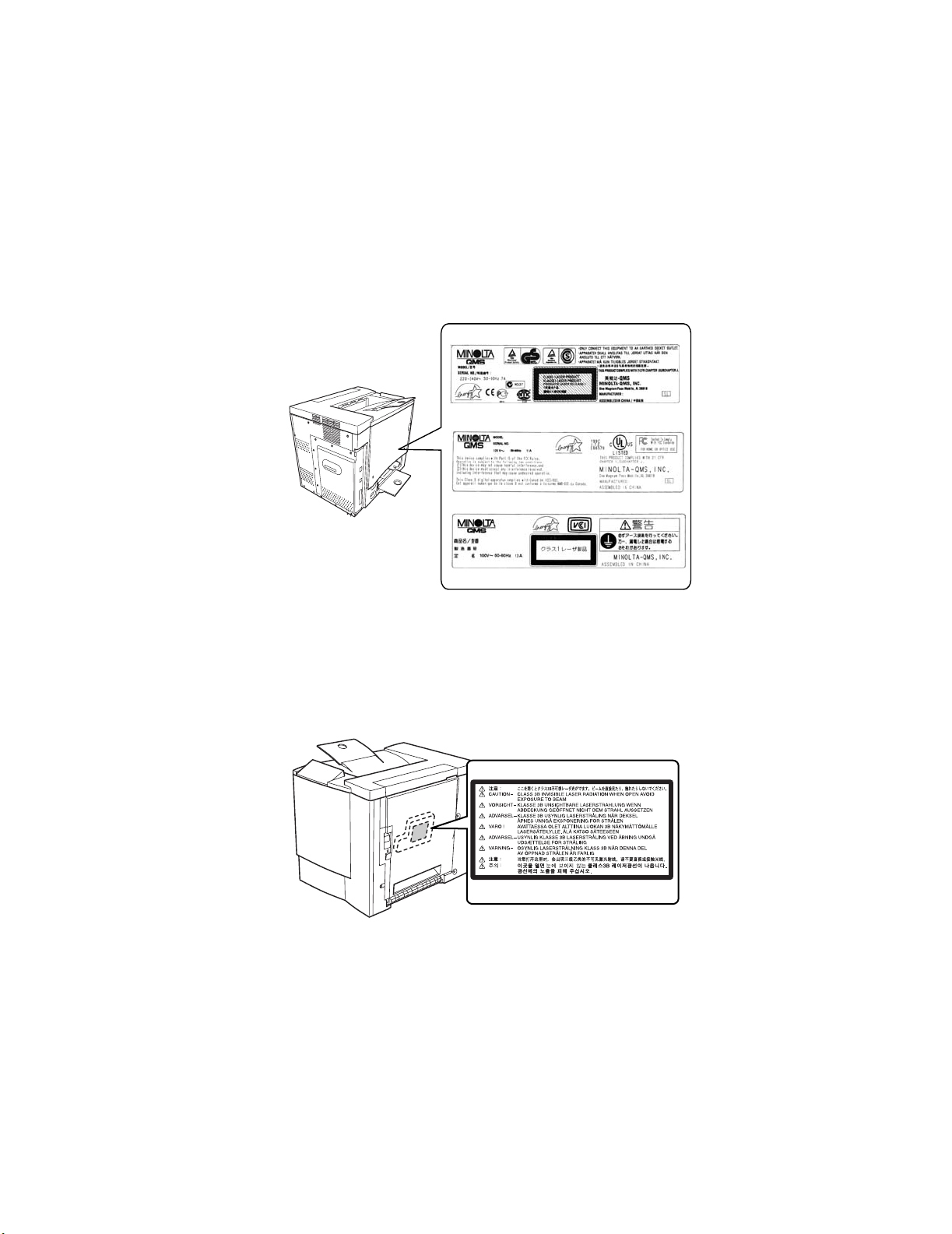
1-7. Laser Safety Label
• A laser safety label is attached to the outside of the machine as shown below.
for 120V
for 220 - 240V
for 100V
4131o003AA
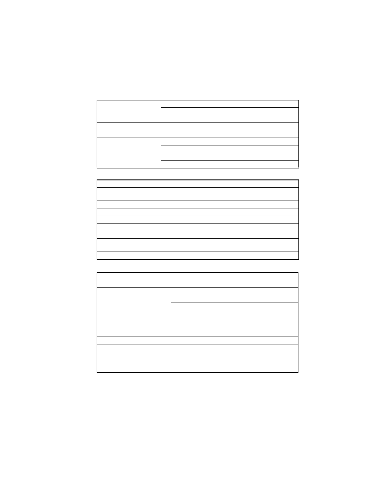
1-8. Laser Caution Label
• A laser caution label is attached to the inside of the machine as shown below.
22
C4131s005AA

1-9. PRECAUTIONS FOR HANDLING THE LASER EQUIPMENT
• When laser protective goggles are to be used, select ones with a lens conforming to the
above specifications.
• When a disassembly job needs to be performed in the laser beam path, such as when
working around the printerhead and PC Drum, be sure first to turn the printer OFF.
• If the job requires that the printer be left ON, take off your watch and ring and wear laser
protective goggles.
• A highly reflective tool can be dangerous if it is brought into the laser beam path. Use
utmost care when handling tools on the user’s premise.
23

24

GENERAL
25


1. Product Specifications
(1) Printer
Type Desktop full-color laser beam printer
Printing method Electrophotographic (two-part imaging cartridge)
Exposure method Laser diode and polygon mirror scanning
Print resolution 600 dpi (dots/inch)
Media sizes A5T, B5T, A4, Letter, Legal
Plain paper (16-24 lb bond, 60-90 g/m2), recycled paper, overhead
Media types
First-page print time
Multi-page print speed
Warm-up time
System speed 101.78 mm/sec.
Paper feed-in method
Paper feed-out method Face-down (tray capacity: 200 sheets)
Drum-charging method Comb electrode scorotron charger
Developing method Single-element developing system
Image transfer method Transport image transfer system
PC drum OPC (Organic Photoconductor)
PC drum cleaning method Blade system
Paper separation method Curvature separation + charge-neutralizing system
Fusing method Heated roller fusing system
Dimensions
Weight 55.1 lbs(25 kg) (without drum cartridge and toner cartridges)
Weight (consumables) 62.4 lbs (28.3 kg) (including drum cartridge and toner cartridges)
Rated power supply voltage 100 V / 120V / 220-240 V
Frequency 50/60 Hz
Maximum power consumption
Operating noise
projector transparencies, letterheads, envelopes (Monarch, Com-10,
DL, C5, C6, Chokei -3, Chokei -4), label sheets, thick paper (91-163
g/m2), government-standard postcards, postcard sheets, Japanese
postcard, and return postcards
Black-and-white printing: 14 sec.
Color printing: 25 sec.
Black-and-white printing: 16 pages/min. (for A4- or Letter-size
pages)
Color printing: 4 pages/min. (for A4- or Letter-size pages)
Within 180 seconds (at a room temperature of 23 °C and at the rated
voltage)
1-way system (maximum 2-way); Expandable to 2-way system by
installing the optional 2nd paper cassette
Manual feed tray (200 sheets of plain paper)
2nd paper cassette (500 sheets of plain paper) (2300 DL & 2350
only)
14.02 in.(356 mm) (W) x 19.69 in.(500 mm) (D) x 15.43 in. (392 mm)
(H)
1100 W or less (100/120 V)
1100 W or less (220-240 V)
During stand-by: 39 dB (A) or less
During printing: 54 dB (A) or less (color printing)
54 dB (A) or less (black-and-white printing)
27
Operating environment
Drum cartridge life 45,000 pages (black/white ratio=5%)
Toner cartridge life (purchased
separately)
Toner cartridge life (enclosed
cartridge)
Options
50-95° F (10-35°C)
15 - 85%
4,500 pages (black/white ratio=5%)
1,500 pages (black/white ratio=5%)
Black: 1,500 pages (black/white ratio=5%)
Color: 1,500 pages (color/white ratio for each color=5%)
Second paper cassette (2300 DL & 2350 only)
Duplex unit
(2) Second paper cassette (Option)
Name Second paper cassette (2300 DL & 2350 only)
Paper
Media sizes A4, Letter
Paper cassette capacity 500 sheets
Paper separation mechanism Paper separator system
Power source Supplied by main unit (DC24 V ±10%)
Drive source Supplied by main unit
Dimensions
Weight 11.7 lbs. (5.3 kg)
Plain paper (16 to 24 lbs.; 60-90 g/m2), recycled paper (16 to 24 lbs.,
60-90 g/m2)
15 in. (380 mm) (W) x 20.1 in. (511 mm) (D) x 6.9 in. (176 mm) (H)
(including the height of the right-side door)
(3) Duplex unit
Name Duplex unit
Paper Plain paper (16 to 24 lbs.; 60-90 g/m2)
Media sizes A4, Letter
Color printing: 2.0 pages/min. (A4- or Letter-size pages)
Print speed (double-sided printing)
Document feeding capacity
Paper transfer baseline Center baseline
Power source Supplied by main unit (DC24 V ±10%)
Drive source Supplied by main unit
Dimensions
Weight 4.4 lbs. (2.0 kg)
Black-and-white printing: 5.0 pages/min. (A4- or Letter-size
pages)
A4/Letter: 2 pages (including the paper path of the paper feedout section)
3.8 in. (97 mm) (W) x 13.4 in. (340 mm) (D) x 13 in. (330 mm)
(H) (including the height of the right-side door)
28

(4) Controller magicolor 2300DL (PWB-P)
CPU D8405 200MHz
Memory configuration
Standard I/F
Network protocol
Network print service
Resolution 600 x 600 dpi, 1200 x 600 dpi, 2400 x 600 dpi
Printer Driver
Compatible clients:
PC IBM PC or compatible
CPU CPU clock of 300 MHz or more recommended
Hard disk free space
RAM
Browser
Standard ROM: 4MB
Standard RAM: 32MB
Ethernet (10/100BASE-TX, RJ-45)
IEEE1284 (Compatible/Nibble/ECP/EPP)
USB Type B connector
TCP/IP
DHCP, ARP/ICMP, BOOTP, SLP, IPP, HTTP, SNMP, LPR
RAW Port Printing (9100)
IPP1.0 (http://Printer IP address/ipp.cgi)
LPD (Queue Name: lp, LP, default, DEFAULT)
OS: Windows 95/98/Me, Windows NT4.0, Windows 2000, Windows XP
Minimum 36 MB
20 MB: Printer drive/Status display
16 MB: Image processing area
At least 16 MB (Windows 95/98/NT4.0)
At least 32 MB (Windows Me)
At least 64 MB (Windows 2000 Professional)
At least 128 MB (Windows XP Home Edition/Professional)
Either of the following browsers is required to use PageScope
Light.
Netscape Navigator Ver. 4.7 or later
Internet Explorer ver5.0
29

(5) Controller magicolor 2350 (PWB-P)
CPU
Memory configuration Boot ROM (512KB); 12MB Flash ROM (supports up to 24MB)
Standard I/F Ethernet (10/100BASE-TX, RJ-45)
Optional I/F Dongle (803.11b & Bluetooth) via parallel
Optional Hard Disk
Resident Emulations
Fonts 137 PostScript fonts, 90 PCL fonts (80 scalable & 10 bitmap)
System Software
Resolution 600 x 600 dpi, 1200 x 600 dpi, 2400 x 600 dpi
Printer Driver
IBM Mercury, Power PC 405, 200 Mhz processor core SOC,
system bus speed of 100 Mhz
128 MB standard, upgreadeable to 384 MB via 1 DIMM slot
IEEE1284 (Compatible/Nibble/ECP/EPP)
USB 1.1
IDE Hard Disk Kit (includes daughterboard, hard disk and TOD
clock); IDE Hard Disk Kit (without hard disk) for third party hard
disks.
PostScript 3, PCL 5, XL, PDF v. 1.3 (requires optional hard
disk), Line printer
Upgradable via FLASH at initial release, later upgradeable via
Mask ROM.
OS: Windows 95/98/Me, Windows NT4.0, Windows 2000, Windows XP
(6) Controller magicolor 2300W (PWB-P)
CPU N1-chip (Naltec original ASIC)
Memory configuration 64 KB (In ASIC)
Standard RAM: 32MB
Standard I/F IEEE1284 (Compatible/Nibble/ECP)
USB Type B connector
Resolution 600 x 600 dpi, 1200 x 600 dpi
Printer Driver OS: Windows 95/98/Me, Windows 2000, Windows XP
Compatible clients:
PC IBM PC or compatible
CPU CPU clock of 300 MHz or more recommended
Hard disk free space Minimum 256 MB
128 MB: Printer drive/Status display
128 MB: Image processing area
RAM At least 16 MB (Windows 95/98)
At least 32 MB (Windows Me)
At least 64 MB (Windows 2000 Professional)
At least 128 MB (Windows XP Home Edition/Professional)
30
 Loading...