

Page 1
Rebuilding Instructions
for the Minolta EP-2120/2121/2130/2130 PRO/2131/2150/
2151/2152/2152 PRO/2153 New-Style* Imaging Unit
© 2000 Katun Corporation
PN 15063
*Minolta item number 4436-200
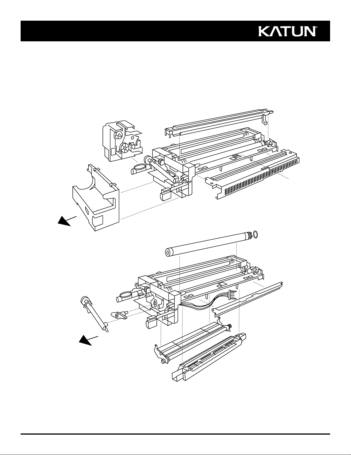
D
A
F
C
Front
Front
H
B
L
J
G
K
N
E
M
Page 2
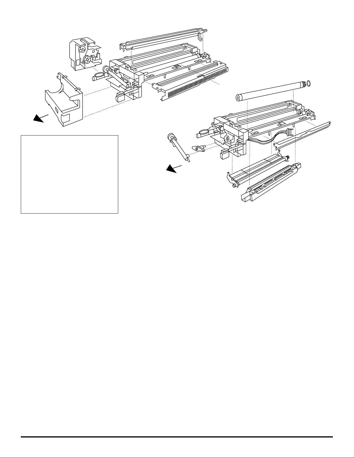
A
B
C
D
F
Front
H
J
L
G
K
E
M
N
Front
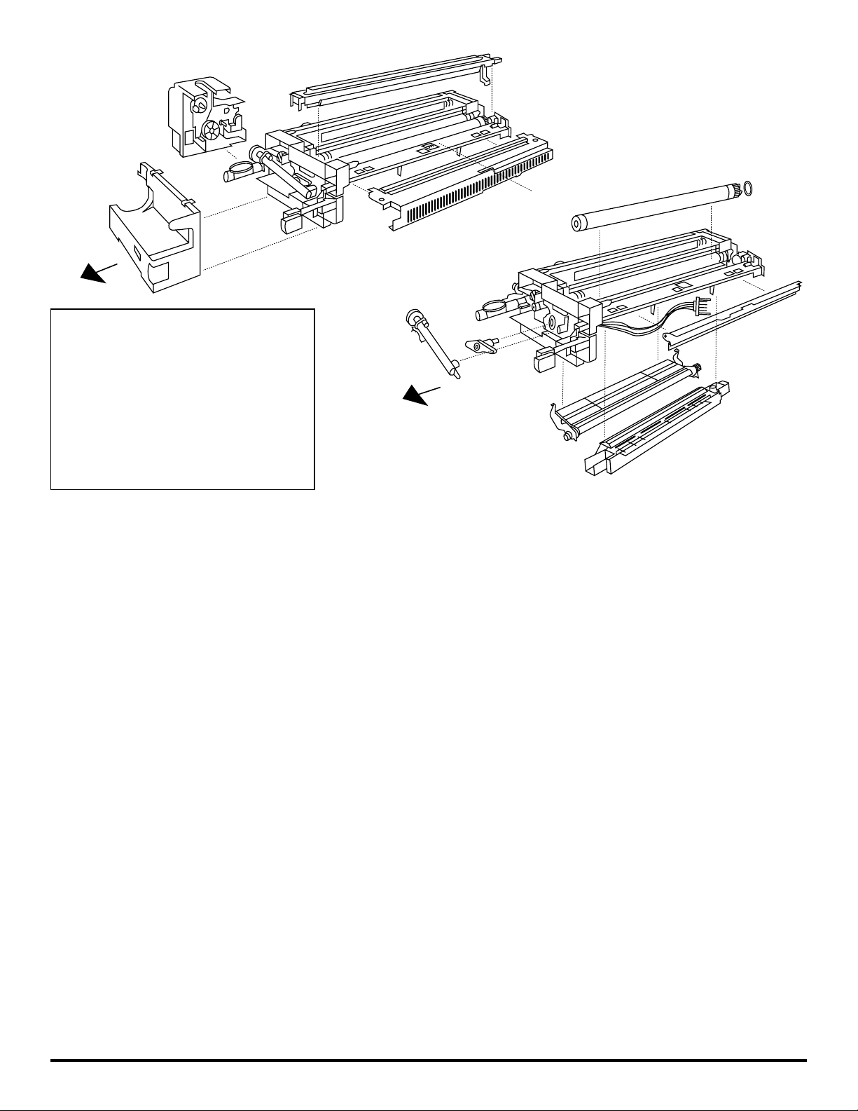
(A) Toner-add gear assembly
(B) Front cover/supply cradle
(C) Cleaner assembly cover
(D) Main charge corona assembly
(E) Drum cleaning blade
(F) Main pressure spring
(G) OPC drum
(H) Auger assembly
(J) Drum holding pin
(K) Gray plastic bushing
(L) Developer unit cover
(M) Transfer corona assembly
(N) Fuse
Rebuilding Instructions for the Minolta EP-2120/2121/2130/
2130 PRO/2131/2150/2151/2152/2152 PRO/2153 Imaging Unit
NOTE: This Katun Rebuild Kit is designed for rebuilding the “new” style imaging unit (OEM PN 4436-200) only. Do not use this Rebuild Kit to rebuild an
“old” style (OEM PN 1276-200), Minolta D-series, Panasonic 1270/1275, or Olympia Omega 1211 imaging unit.
Disassembly:
1. Remove the toner-add gear assembly (A) from the imaging unit by removing one screw and disconnecting the two-pin connector.
2. Remove two screws from the bottom of the front cover/supply cradle (B). Remove the front cover/supply cradle by lifting in an upward and frontward
direction, making sure the two tabs clear the corresponding notches. Remove the totalizer/copy counter from the front cover/supply cradle by removing
one screw.
3. Remove the cleaner assembly cover (C) by removing two screws from top and making sure two tabs on bottom clear the corresponding notches.
CAUTION: Do not lose the cleaning blade lifter tab.
4. Holding together the two tabs on the front of the main charge corona assembly (D), pull this assembly upward to remove it.
5. Remove the used drum cleaning blade (E) by unhooking the main pressure spring (F), and removing one screw from each end. Discard the used drum
cleaning blade.
6. To remove the used OPC drum (G):
• Remove the auger assembly (H) by removing one screw.
• Remove the drum holding pin (J) by removing two screws.
• Slide the used OPC drum frontward, and lift it out of the imaging unit frame.
IMPORTANT: Retain the gray plastic bushing (K) from the drum gear flange for reinstallation with the new OPC drum.
7. Remove the developer unit cover (L) by removing one spring from each end, and two screws from the top.
8. Thoroughly vacuum the developer assembly and cleaner assembly to remove used developer and toner.
CAUTION: Vacuum carefully to avoid damaging either the magnetic roller, or the Mylar seals in the developer and cleaner assemblies.
9. Remove the transfer corona assembly (M) from bottom of imaging unit by removing the two screws that secure it to the frame.
10. Remove the two felt seals from the outer ends of the OPC drum cradle. Mark exact locations of old seals for reference when installing new seals.
For best results, use isopropyl alcohol to remove any remaining adhesive. IMPORTANT: Thoroughly wipe all alcohol from the area, and allow any
remaining alcohol to evaporate before installing the new seals and OPC drum.
Page 3

Rebuilding:
11. IMPORTANT: Always replace the fuse (N) when rebuilding the imaging unit. To replace the used fuse with the new fuse provided in the Katun
Rebuild Kit:
• Use only a low-wattage soldering iron (35 watts). Excessive heat can damage the fuse.
• Disconnect the five-pin connector from the ATDC sensor.
• Carefully pull the wire harness toward the rear of the imaging unit. Remove the two screws connecting the imaging unit connector to the rear of the unit.
Carefully pull the imaging unit connector until the black insulating tube covering the fuse (N) is clear of the imaging unit.
• Cut a 15 mm slit in the black insulating tube. Cut off the existing fuse lead approximately 10-15 mm from the plastic connector housing.
• Remove the insulating tube. Cut off the remaining fuse lead approximately 10-15 mm from the plastic connector housing.
• Solder the new fuse lead onto one of the existing leads. Replace the insulating tube and solder the remaining fuse lead. Seal the insulating tube with
electrical tape.
• Reinstall the imaging unit connector by replacing two screws. Pull the wire harness toward the front of the imaging unit, and reconnect the five-pin
connector to the ATDC sensor.
12. Replace used transfer corona wire with new, precut corona wire (provided in the Katun Rebuild Kit). Reattach the transfer corona assembly (M), securing
it with the two screws removed in step 9.
13. Install two new felt seals (provided in the Katun Rebuild Kit) by peeling away adhesive backing and placing new seals in exact locations of old seals
removed in step 10.
14. Reinstall the developer unit cover (L) and springs, securing the cover with the two screws removed in step 7.
15. Place the gray, plastic bushing (K), removed in step 6, over the gear flange of the new Katun OPC drum (provided in Katun Rebuild Kit). Install the new
Katun OPC drum, aligning the bushing tab with the notch at the rear of the imaging unit. Reinstall the drum holding pin (J), and secure it with the two
screws removed in step 6.
16. Reinstall the auger assembly (H) and secure it with the single screw removed in step 6.
17. Using Kynar powder or new toner, dust the surface of the new Katun OPC drum and the edge of the new Katun drum cleaning blade (provided in the
Katun Rebuild Kit), to ensure proper lubrication.
18. Install the new Katun drum cleaning blade. Secure it by replacing the two screws removed in step 5 and rehooking the main pressure spring (F). Using
the gear end of the drum, manually rotate the drum clockwise a minimum of one full revolution to properly distribute powder and
minimize the possibility of “blade flip.” NOTE: If the drum is difficult to rotate or “binds,” repeat step 17.
19. Replace used main charge corona wire with the new, precut Katun corona wire (provided in the Katun Rebuild Kit). Gently snap the main charge corona
assembly (D) back into place.
20. Reinstall the cleaner assembly cover (C), and secure it with the two screws removed in step 3.
21. Remount the totalizer/copy counter, and secure it with the single screw removed in step 2.
22. Reattach the front cover/supply cradle (B) by sliding two tabs into place and securing it with the two screws removed in step 2.
23. Reattach the toner-add gear assembly (A), making sure to reconnect the two-pin connector, and secure it by replacing the single screw removed in
step 1.
24. Install the new developer cartridge (provided in the Katun Rebuild Kit) by swinging the front cover down and swinging the supply cradle outward. With
the new developer cartridge installed, swing the supply cradle inward until it locks in position and close the front cover. CAUTION: Do not mistakenly
install a toner cartridge.
IMPORTANT: If the imaging unit will be transported after rebuilding:
• position the cleaning blade lifter tab on the imaging unit frame so that the drum cleaning blade is not in contact with the drum;
• do not remove the seal from the developer cartridge until ready to install the imaging unit.
Installation:
25. Turn off the copier and unplug the power cord from the wall outlet.
26. Remove the seal from the developer cartridge.
27. Install the imaging unit by fitting it onto the rails inside the copier and sliding it inward until you hear a click. Then pull on the unit to ensure it is locked
in position.
28. Plug the power cord into the wall outlet and turn on the copier. While the copier warms up a “1” will flash on the control panel.
29. When the warm-up period is complete, the copier will begin a three-to-five minute recharge cycle. During the recharge cycle, the copier’s drive motor will
engage and the LED segments that form a “0” on the control panel will flash on and off in a clockwise direction, indicating the contents of the developer
cartridge are being added and the ATDC value is being set.
30. After the recharge cycle is complete, a “1” will light up continuously on the control panel. NOTE: If an error code is displayed, ensure that the seal has
been removed from the developer cartridge and recheck all wiring connections on the imaging unit.
31. Open the front cover, swing the supply cradle outward and remove the empty developer cartridge. Then install a new toner
cartridge into the supply cradle and close the front cover.
Page 4
A
B
C
D
F
Front
H
J
L
G
K
E
M
N
Front
Instrucciones Para Reconstruir Las Unidades de Imágenes
Minolta EP 2120/2121/2130/2130 PRO/2131/2150/2151/2152/
2152 PRO/2153
NOTA: Este kit de reconstrucción de Katun se ha diseñado sólo para reconstruir las unidades de imágenes “nuevas” (Ref. del fabricante original 4436-200).
No utilice este kit de reconstrucción para reconstruir las unidades de imágenes “antiguas” (Ref. del fabricante original 1276-200) Minolta serie D,
Panasonic 1270/1275 u Olympia Omega 1211.
Desmontaje:
1. Para retirar el conjunto del engranaje de agregado de toner (A) de la unidad de imágenes retire el tornillo y desconecte el conector de dos espigas.
2. Para retirar la cubierta delantera/soporte del suministro (B); en primer lugar, retire los dos tornillos de la parte inferior de la cubierta, y luego levántela y
muévala hacia adelante, asegurándose de desconectar las dos lengüetas de las muescas correspondientes. Para retirar el contador de copias de la cubierta delantera/soporte del suministro retire el tornillo.
3. Para retirar la cubierta del conjunto de limpieza (C), retire los dos tornillos de la parte superior, asegurándose de desconectar las dos lengüetas de la
parte inferior de las muescas correspondientes. PRECAUCION: No pierda la lengüeta para levantar la lámina limpiadora.
4. Para retirar el conjunto de corona de carga principal (D), sujete las dos lengüetas de la parte delantera del conjunto y muévalas hacia arriba.
5. Para retirar la lámina limpiadora del tambor usada (E), desenganche el muelle de presión principal (F) y retire el tornillo de cada extremo. Deseche la
lámina limpiadora del tambor usada.
6. Para retirar el tambor OPC usado (G):
• Retire el conjunto pasador (H), retirando un tornillo.
• Retire el pasador de sujeción del tambor (J), retirando los dos tornillos.
• Deslice el tambor OPC usado hacia adelante y retírelo del armazón de la unidad de imágenes.
IMPORTANTE: Guarde el manguito de plástico gris (K) que se encuentra en la brida del engranaje del tambor para volver a instalarlo con el nuevo
tambor OPC.
7. Para retirar el conjunto de la unidad de revelado (L), retire el muelle de cada extremo y los dos tornillos de la parte superior.
8. Para retirar el revelador y el toner usados, aspire completamente el conjunto de limpieza y el conjunto de la unidad de revelado. PRECAUCION: Aspire con
mucho cuidado para no dañar el rodillo magnético o los sellos Mylar, ubicados en los conjuntos de limpieza y de la unidad de revelado.
9. Para retirar el conjunto de corona de transferencia (M) de la parte inferior de la unidad de imágenes, retire los dos tornillos que sostienen este conjunto
al armazón.
10. Retire los dos sellos de fieltro de los extremos exteriores del soporte del tambor OPC. Antes de instalar los nuevos sellos, marque la ubicación exacta
de los antiguos sellos como referencia. Para obtener mejores resultados, utilice alcohol isopropílico para retirar todos los restos de adhesivo. IMPORTANTE: Limpie completamente el alcohol del área con un paño y espere a que se evaporen todos los restos de alcohol antes de instalar los sellos y
el tambor OPC nuevos.
(A) conjunto del engranaje de agregado de toner
(B) cubierta delantera/soporte del suministro
(C) cubierta del conjunto de limpieza
(D) conjunto de corona de carga principal
(E) lámina limpiadora del tambor
(F) muelle de presión principal
(G) tambor OPC
(H) conjunto pasador
(J) pasador de sujeción del tambor
(K) manguito de plástico gris
(L) cubierta de la unidad de revelado
(M) conjunto de corona de transferencia
(N) fusible
Parte
delantera
Parte
delantera
Page 5

Reconstrucción:
11. IMPORTANTE: Siempre reemplace el fusible (N) al reconstruir la unidad de imágenes. Para reemplazar el fusible usado por el nuevo fusible, que viene
en el kit de reconstrucción de Katun, siga las siguientes instrucciones:
• Use solamente un soldador de baja potencia (35 vatios). El calor excesivo puede dañar el fusible.
• Desconecte el conector de cinco espigas del sensor ATDC.
• Tire cuidadosamente del cableado hacia la parte posterior de la unidad de imágenes. Retire los dos tornillos que unen el conector de la unidad de
imágenes a la parte posterior de dicha unidad. Separe cuidadosamente el conector de la unidad de imágenes hasta que el tubo negro de aislamiento que
cubre el fusible (N) se desprenda de la unidad de imágenes.
• Haga una ranura de 15 mm en el tubo negro de aislamiento. Corte la punta expuesta del fusible, aproximadamente a 10 o 15 mm de la cubierta del
conector plástico.
• Retire el tubo de aislamiento. Corte la punta restante del fusible, aproximadamente a 10 o 15 mm de la cubierta del conector plástico.
• Suelde la nueva punta del fusible a una de las puntas existentes. Vuelva a colocar el tubo de aislamiento y suelde la punta restante del fusible. Selle el
tubo de aislamiento con cinta aislante.
• Para volver a instalar el conector de la unidad de imágenes, coloque los dos tornillos, tire del cableado hacia la parte delantera de la unidad de imágenes
y, vuelva a conectar el conector de cinco espigas al sensor ATDC.
12. Reemplace los hilos de corona de transferencia usados con los nuevos hilos de corona precortados (vienen en el kit de reconstrucción de Katun). Vuelva
a montar el conjunto de los hilos de corona de transferencia (M) y coloque los dos tornillos que se retiraron en el paso Nº 9.
13. Para instalar los dos nuevos sellos de fieltro (vienen en el kit de reconstrucción de Katun), retire la cinta adhesiva y coloque los nuevos sellos en las mismas ubicaciones de los sellos antiguos que se retiraron en el paso Nº 10.
14. Vuelva a instalar la tapa de la unidad de revelado (L) y los muelles, y sujete la tapa con los dos tornillos que se retiraron en el paso Nº 7.
15. Coloque el manguito de plástico gris (K), que se retiró en el paso Nº 6, sobre la brida del engranaje del nuevo tambor OPC de Katun (viene en el kit de
reconstrucción de Katun). Instale el nuevo tambor OPC de Katun alineando la lengüeta del manguito con la muesca que se encuentra en la parte posterior
de la unidad de imágenes. Vuelva a instalar el pasador de sujeción del tambor (J), y sujételo con los dos tornillos que se retiraron en el paso Nº 6.
16. Vuelva a instalar el conjunto pasador (H) y coloque el tornillo que se retiró en el paso Nº 6.
17. Para asegurar una lubricación adecuada, coloque polvo Kynar o toner nuevo en la super ficie del nuevo tambor OPC de Katun y en el borde de la nueva
lámina limpiadora del tambor Katun (viene en el kit de reconstrucción de Katun).
18. Instale la nueva lámina limpiadora del tambor Katun. Coloque los dos tornillos que se retiraron en el paso Nº 5 y vuelva a enganchar el muelle de presión
principal (F). Con el extremo del engranaje del tambor, gire manualmente el tambor en el sentido de las agujas del reloj una revolución completa por lo
menos, para distribuir adecuadamente el polvo y reducir la posibilidad de que “la lámina se invierta”. NOTA: Si no puede girar el tambor con facilidad o si
éste se “traba”, repita el paso Nº 17.
19. Reemplace los hilos de corona de carga principal usados con los nuevos hilos de corona precortados de Katun que vienen en el kit de reconstrucción.
Suavemente devuelva en su lugar con un chasquido el conjunto de corona de carga principal (D).
20. Vuelva a instalar la cubierta del conjunto de limpieza (C) y coloque los dos tornillos que se retiraron en el paso Nº 3.
21. Vuelva a instalar el contador de copias, y asegúrelo con el único tornillo que se retiró en el paso Nº 2.
22. Vuelva a montar la cubierta delantera/soporte del suministro (B) conectando las dos lengüetas y luego coloque los dos tornillos que se retiraron en el
paso Nº 2.
23. Vuelva a colocar el conjunto del engranaje de agregado toner (A) asegurándose de volver a unir el conector de dos espigas, y luego coloque el tornillo
que se retiró en el paso Nº 1.
24. Instale el nuevo cartucho del revelador (viene en el kit de reconstrucción de Katun) moviendo la cubierta delantera hacia abajo y el soporte del suministro
hacia fuera. Una vez que instale el nuevo cartucho del revelador, deslice el soporte del suministro hacia adentro hasta que quede bien ajustado y cierre la
cubierta delantera. PRECAUCION: No instale por error un cartucho de toner.
IMPORTANTE: Si se va a transportar la unidad de imágenes después de la reconstrucción:
• coloque la lengüeta para levantar la lámina limpiadora en el armazón de la unidad de imágenes, de modo que la lámina limpiadora del tambor no entre
en contacto con el tambor;
• no retire el sello de la botella del cartucho del revelador hasta instalar la unidad de imágenes.
Instalación:
25. Apague la copiadora y desenchufe el cable de alimentación de la toma de la corriente.
26. Retire el sello del cartucho del revelador.
27. Para instalar la unidad de imágenes, colóquela sobre los rieles en el interior de la copiadora y deslícela hacia adentro hasta que se escuche un “clic”.
Posteriormente tire de la unidad para cerciorarse de que ha quedado bien ajustada.
28. Enchufe el cable de alimentación a la toma de la corriente y encienda la copiadora. Mientras la copiadora comienza a funcionar, aparecerá un “1” parpadeando en el panel de control.
29. Una vez que se haya completado el período de precalentamiento, la copiadora comenzará un ciclo de recarga de tres a cinco minutos. Durante el ciclo de
recarga, se accionará el motor de tracción de la copiadora, y los segmentos de los diodos luminosos (LED) que forman un “O” en el panel de control
comenzarán a encenderse y apagarse en el sentido de las agujas del reloj. Esto indica que se está agregando el contenido del cartucho del revelador y que
se están fijando los valores del sensor ATDC.
30. Después de que se ha ya completado el ciclo de recarga, se mantendrá encendido un “1” en el panel de control. NOTA: Si se visualiza un código de
error, cerciórese de que se ha ya retirado el sello del cartucho del revelador y vuelva a revisar las conexiones del cableado de la unidad de imágenes.
31. Abra la cubierta delantera, mueva el soporte del suministro hacia fuera y retire el cartucho del revelador vacío. Luego instale el nuevo cartucho de toner
en el soporte del suministro y cierre la cubierta delantera.
Page 6

A
B
C
D
F
Front
H
J
L
G
K
E
M
N
Front
Erneuerungsanleitung für die Trommeleinheit in
Minolta EP-2120/2121/2130/2130 PRO/2131/2150/2151/2152/
2152 PRO/2153
HINWEIS: Dieses Katun Erneuerungskit ist nur für die “neue” Trommeleinheit (Original Art.-Nr. 4436-200) bestimmt. Dieses Erneuerungskit nicht zur
Erneuerung der “alten” Trommeleinheit (Original Art.-Nr. 1276-200) der Minolta D-Serie bzw. Panasonic 1270/1275 oder Olympia Omega 1211 verwenden.
Demontage:
1. Die Tonernachfülleinheit (A) durch Lösen der Schraube und Trennen der zweipoligen Steckverbindung von der Trommeleinheit abnehmen.
2. Die beiden Schrauben an der Unterseite der Frontabdeckung/Haltevorrichtung (B) entfernen. Die Frontabdeckung/Haltevorrichtung gleichzeitig nach vorne
und oben herausziehen; dabei darauf achten, daß die beiden Kunststoff-Stifte aus ihren Schlitzen herauskommen. Den Kopienzähler durch Lösen der
Schraube von der Frontabdeckung/Haltevorrichtung abnehmen.
3. Die beiden Schrauben an der Abdeckung der Reinigungseinheit (C) entfernen und die Abdeckung abnehmen; dabei darauf achten, daß die beiden
Kunststoff-Stifte an der Unterseite aus ihren Schlitzen herauskommen. VORSICHT:Achten Sie darauf, den Kunststoff-Stift zum Herausheben des
Trommelwischers nicht zu verlieren.
4. Die beiden Kunststoff-Stifte vorne an der Haupt-Ladecorona (D) festhalten und die Einheit nach oben herausziehen.
5. Den Trommelwischer (E) durch Aushängen der Haupt-Andruckfedern (F) und Lösen der beiden Schrauben an den Enden ausbauen. Den gebrauchten
Trommelwischer entsorgen.
6. Zum Ausbau der OPC-Trommel (G):
• Die Transportschnecke (H) durch Lösen der Schraube entfernen.
• Die Trommelflansch-Halterung (J) durch Lösen der beiden Schrauben entfernen.
• Die OPC-Trommel nach vorne schieben und aus der Trommeleinheit herausheben.
WICHTIG: Die graue Kunststoffhülse (K) vom Trommel-Antriebsflansch aufbewahren. Sie wird mit der neuen OPC-Trommel wiederverwendet.
7. Die Abdeckung der Entwicklereinheit (L) durch Aushängen der beiden Federn an den Enden und Entfernen von zwei Schrauben an der Oberseite
abnehmen.
8. Entwickler- und Reinigungseinheit gründlich aussaugen, um gebrauchten Toner und Entwickler zu entfernen. VORSICHT:Beim Aussaugen vorsichtig
vorgehen, um die Magnetwalze bzw. die Mylar-Dichtungen in Entwickler- und Reinigungseinheit nicht zu beschädigen.
9. Die Übertragungscorona (M) durch Lösen der beiden Befestigungsschrauben von der Unterseite der Trommeleinheit abnehmen.
10. Die beiden Dichtungsfilze an den äußeren Enden der OPC-Trommelaufnahme entfernen. Die Position der alten Filze zur späteren Installation der neuen
Filze genau markieren. Um alle Klebstoffreste zu entfernen, empfiehlt es sich, Isopropylalkohol (Katun Art.- Nr. 11703966) zu verwenden. WICHTIG: Vor
Einbau der neuen Filze und der OPC-Trommel den Alkohol gut abwischen und eventuelle Rückstände verdunsten lassen.
(A) Tonernachfülleinheit
(B) Frontabdeckung/Haltevorrichtung
(C) Abdeckung der Reinigungseinheit
(D) Haupt-Ladecorona
(E) Trommelwischer
(F) Haupt-Andruckfedern
(G) OPC-Trommel
(H) Transportschnecke
(J) Trommelflansch-Halterung
(K) graue Kunststoffhülse
(L) Abdeckung der Entwicklereinheit
(M) Übertragungscorona
(N) Sicherung
Vorderseite
Vorderseite
Page 7

Zusammenbau:
11. WICHTIG: Bei Erneuerung der Trommeleinheit immer die Sicherung (N) austauschen. Zum Austausch der gebrauchten Sicherung gegen die im Katun
Erneuerungskit enthaltene neue Sicherung folgendermaßen vorgehen:
• Nur einen Lötkolben mit geringer Leistung (35 W) verwenden. Zu hohe Temperatur kann die Sicherung beschädigen.
• Den fünfpoligen Steckverbinder für den ATDC-Sensor trennen.
• Den Kabelbaum vorsichtig in Richtung Rückseite der Trommeleinheit ziehen. Die beiden Befestigungsschrauben der Steckverbindung an der Rückseite
der Trommeleinheit entfernen. Die Steckverbindung vorsichtig aus der Trommeleinheit herausziehen, bis der schwarze Isolierschlauch (unter dem sich
die Sicherung (N) befindet) freikommt.
• Einen 15 mm langen Schlitz in den schwarzen Isolierschlauch schneiden und den zum Vorschein kommenden Anschlußdraht der Sicherung ca.
10-15 mm von der Steckverbindung entfernt abschneiden.
• Den Isolierschlauch entfernen. Den verbleibenden Anschlußdraht der Sicherung ebenfalls ca. 10-15 mm von der Steckverbindung entfernt abschneiden.
• Die neue Sicherung an einen der vorhandenen Drähte anlöten. Den Isolierschlauch über die neue Sicherung schieben und den verbleibenden
Anschlußdraht anlöten. Den Isolierschlauch mit Isolierband verschließen.
• Zum Wiedereinbauen die beiden Schrauben in die Steckverbindung der Trommeleinheit eindrehen. Den Kabelbaum in Richtung Vorderseite der
Trommeleinheit ziehen und den fünfpoligen Steckverbinder des ATDC-Sensors wieder anschließen.
12. Den gebrauchten Übertragungscoronadraht gegen den neuen, vorgeschnittenen Coronadraht (im Katun Erneuerungskit enthalten) austauschen. Die Übertragungscorona (M) mit den beiden in Schritt 9 entfernten Schrauben wieder befestigen.
13. Die Schutzfolie von den beiden neuen Dichtungsfilzen (im Katun Erneuerungskit enthalten) abziehen und die Filze in exakt derselben Position wie die in
Schritt 10 entfernten alten Filze aufkleben.
14. Die Abdeckung der Entwicklereinheit (L) und die Federn wieder anbringen und mit den beiden in Schritt 7 entfernten Schrauben befestigen. Keinen
Entwickler einfüllen
!
15. Die in Schritt 6 entfernte graue Kunststoffhülse (K) auf den Antriebsflansch der neuen OPC-Trommel (im Katun Erneuerungskit enthalten) aufsetzen. Die
neue OPC-Trommel so installieren, daß der Kunststoff-Stift an der Hülse in die Aussparung an der Rückseite der Trommeleinheit eingreift. Die
Trommelflansch-Halterung (J) wieder anbringen und mit den in Schritt 6 entfernten Schrauben sichern.
16. Die Transportschnecke (H) wieder mit der in Schritt 6 entfernten Schraube befestigen.
17. Die Ober fläche der neuen OPC-Trommel und die Kante des neuen Trommelwischers (im Katun Erneuerungskit enthalten) mit Kynar-Pulver oder neuem
Toner bestäuben, um eine ausreichende Schmierung zu gewährleisten.
18. Den Katun Trommelwischer mit den beiden in Schritt 5 entfernten Schrauben montieren und die Haupt-Andruckfedern (F) wieder einhängen. Die Trommel
von Hand im Uhrzeigersinn um mindestens eine Umdrehung drehen, damit das Pulver gut verteilt und die Gefahr des “Wischer-Umklappens” minimiert
wird. HINWEIS: Läßt sich die Trommel nur schwer oder gar nicht drehen, Schritt 17 wiederholen.
19. Den gebrauchten Hauptcoronadraht gegen den neuen, vorgeschnittenen Coronadraht (im Katun Erneuerungskit enthalten) austauschen. Die HauptcoronaEinheit (D) vorsichtig wieder einrasten lassen.
20. Die Abdeckung der Reinigungseinheit (C) wieder aufsetzen und mit den beiden in Schritt 3 entfernten Schrauben befestigen.
21. Den Kopienzähler mit der in Schritt 2 entfernten Schraube montieren.
22. Die Frontabdeckung/Haltevorrichtung (B) durch Einsetzen der beiden Kunststoff-Stifte wieder anbringen und mit den beiden in Schritt 2 entfernten
Schrauben befestigen.
23. WICHTIG: Die zweipolige Steckverbindung wieder anbringen. Die Tonernachfülleinheit (A) mit der in Schritt 1 entfernten Schraube wieder befestigen.
24. Zum Einsetzen der neuen Entwicklerkartusche (im Katun Erneuerungskit enthalten) die Frontabdeckung herunterklappen und die Haltevorrichtung herausklappen. Entwicklerkartusche nicht
öffnen! Nach dem Einsetzen der neuen Entwicklerkartusche die Haltevorrichtung wieder einklappen, bis sie ein-
rastet, und die Frontabdeckung schließen. VORSICHT: Nicht versehentlich eine Tonerkartusche installieren.
WICHTIG: Falls die Trommeleinheit nach der Erneuerung transportiert wird:
• Den Kunststoff-Stift des Trommelwischers am Rahmen der Trommeleinheit anbringen, so daß der Trommelwischer nicht mit der Trommel in
Berührung kommt.
• Die Entwicklerkartusche erst öffnen, wenn die Trommeleinheit installiert werden soll.
Installation:
25. Kopierer ausschalten und Netzstecker ziehen.
26. Die Schutzfolie von der Entwicklerkartusche abziehen.
27. Die Trommeleinheit in die Schienen im Kopierer einsetzen und einschieben, bis sie hörbar einrastet. An der Einheit ziehen, um sicherzustellen, daß sie
wirklich eingerastet ist.
28. Netzstecker einstecken und Kopierer einschalten. Während das Gerät aufheizt, blinkt in der Anzeige eine “1”.
29. Wenn der Kopierer aufgeheizt ist, schaltet sich der Antriebsmotor ein und der Kopierer läuft für ca. 3-5 Minuten. In der Anzeige blinken die eine “0”
bildenden Leuchtdioden reihum im Uhrzeigersinn. Die zeigt an, daß der Entwickler aus der Kartusche geladen und der ATDC-Wert eingestellt wird.
30. Nach Abschluß des Ladezyklus’ leuchtet in der Anzeige eine “1” auf. HINWEIS: Erscheint ein Fehlercode, sicherstellen, daß die Schutzfolie von der
Entwicklerkartusche abgezogen ist und alle Kabelverbindungen an der Trommeleinheit angeschlossen sind.
31. Die Frontabdeckung öffnen, die Haltevorrichtung herausklappen und die Entwicklerkartusche entfernen. Eine neue Tonerkartusche in die Haltevorrichtung
einsetzen und die Frontabdeckung schließen.
Page 8

Instructions pour la remise à neuf de l’unité image du
Minolta EP-2120/2121/2130/2130 PRO/2131/2150/2151/2152/
2152 PRO/2153
N.B. : ce kit de remise à neuf Katun est conçu pour la remise à neuf seulement du « nouveau » type d’unité image (no de pièce OEM : 4436-200). Ne pas
utiliser ce kit pour remettre à neuf une unité image d’un « ancien » type (no de pièce OEM : 1276-200) Minolta série D, Panasonic 1270/1275 ou
Olympia Omega 1211.
Démontage :
1. Retirer de l’unité image l’ensemble pignons d’alimentation toner (A) en dévissant la vis et en détachant le raccord à deux fiches.
2. Dévisser les deux vis au fond du couvercle avant/boîtier d'alimentation (B). Retirer le couvercle avant/boîtier d'alimentation en le soulevant vers l’avant et
en s’assurant que les deux pattes sont dégagées de leur logement. Enlever le compteur (initialiseur) du couvercle avant/boîtier d'alimentation en dévissant
la vis.
3. Retirer le couvercle de l’ensemble nettoyage (C) en dévissant les deux vis du haut et en s’assurant que les deux pattes du bas sont dégagées de leur logement. ATTENTION : ne pas perdre la patte de soulèvement de la raclette de nettoyage.
4. En tenant les deux pattes à l’avant de l’ensemble corona charge principale (D), tirer l’ensemble vers le haut pour l’enlever.
5. Retirer la raclette de nettoyage tambour usagée (E) en décrochant le ressort de pression principal (F), puis dévisser la vis à chaque extrémité. Jeter la
raclette de nettoyage tambour usagée.
6. Pour retirer le tambour OPC usagé (G) :
• Retirer l’ensemble vis sans fin (H) en dévissant la vis.
• Retirer la goupille de maintien du tambour (J) en dévissant deux vis.
• Faire glisser vers l’avant le tambour OPC usagé et le soulever pour l’enlever du châssis de l’unité image.
IMPORTANT : mettre de côté la bague en plastique grise (K) du flasque de l’engrenage tambour pour la réinstaller ultérieurement sur le nouveau
tambour OPC.
7. Retirer le couvercle de l’unité de développement (L) en retirant le ressort à chaque extrémité et les deux vis du haut.
8. Nettoyer entièrement l’unité de développement à l’aspirateur afin d’enlever le développeur et le toner usagés.
ATTENTION : nettoyer avec soin pour éviter d’endommager le rouleau magnétique ou les joints Mylar des ensembles développement et nettoyage.
9. Retirer l’ensemble corona transfert (M) du bas de l’unité image en dévissant les deux vis qui maintiennent le châssis.
10. Décoller les deux joints de feutre des extrémités extérieures du boîtier tambour OPC. Marquer précisément l’emplacement des joints usagés pour réin-
staller correctement les nouveaux joints. Pour de meilleurs résultats, utiliser de l’alcool isopropylique pour nettoyer le restant d’adhésif. IMPORTANT :
avant de replacer les nouveaux joints et le tambour OPC, bien essuyer tout l’alcool sur la surface du boîtier et laisser le restant d’alcool s’évaporer.
(A) Ensemble pignons d’alimentation toner
(B) Couvercle avant/boîtier d’alimentation
(C) Couvercle de l’ensemble nettoyage
(D) Ensemble corona charge principale
(E) Raclette de nettoyage tambour
(F) Ressort de pression principal
(G) Tambour OPC
(H) Ensemble vis sans fin
(J) Goupille de maintien du tambour
(K) Bague en plastique grise
(L) Couvercle de l’unité de développement
(M) Ensemble corona transfert
(N) Fusible
A
B
C
D
F
Front
Devant
H
J
L
G
K
E
M
N
Front
Devant
Page 9

Remise à neuf :
11. IMPORTANT : toujours remplacer le fusible (N) lors de la remise à neuf de l’unité tambour. Pour remplacer le fusible usagé avec le nouveau fusible
fourni dans le kit de remise à neuf Katun :
• Utiliser un fer à souder de faible puissance (35 watts). Une chaleur excessive pourrait endommager le fusible.
• Déconnecter le raccord à cinq fiches du détecteur ATDC.
• Tirer doucement le harnais vers l’arrière de l’unité image. Enlever les deux vis qui connectent le raccord de l’unité image à l’arrière de l’unité image. Tirer
doucement le raccord de l’unité image jusqu’à ce que le tube isolant noir recouvrant le fusible (N) soit dégagé de l’unité image.
• Découper une fente de 15 mm dans le tube isolant noir. Couper le fil exposé du fusible à environ 10 à 15 mm du boîtier en plastique du raccord.
• Enlever le tube isolant. A environ 10 à 15 mm du boîtier en plastique du raccord, couper le fil du fusible restant.
• Souder un des fils du nouveau fusible à l’un des fils exposés. Remettre en place le tube isolant et souder le fil restant du fusible. Enrouler le tube isolant
avec du chatterton.|
• Réinstaller le raccord de l’unité image en revissant les deux vis. Tirer le harnais de câbles vers l’avant de l’unité image et connecter le raccord à cinq
fiches du détecteur ATDC.
12. Remplacer le fil corona transfert usagé avec le nouveau fil corona précoupé (fourni dans le kit Katun de remise à neuf). Rattacher l’ensemble corona
transfert (M) en revissant les deux vis retirées à l’étape 9.
13. Installer les deux nouveaux joints de feutre (fournis dans le kit Katun de remise à neuf) en décollant la protection adhésive et en les plaçant exactement à
l’endroit des anciens joints enlevés à l’étape 10.
14. Réinstaller le couvercle de l’unité de développement (L) et les ressorts, et les rattacher avec les deux vis retirées à l’étape 7.
15. Replacer la bague de plastique grise (K), retirée à l’étape 6, sur le flasque de l’engrenage du nouveau tambour OPC Katun (fourni dans le kit Katun de
remise à neuf). Installer le nouveau tambour OPC Katun en alignant la patte de la bague sur l’encoche à l’arrière de l’unité image. Réinstaller la goupille de
maintien du tambour (J) en revissant les deux vis retirées à l’étape 6.
16. Réinstaller l’ensemble vis sans fin (H) en le rattachant avec la vis retirée à l’étape 6.
17. En utilisant de la poudre Kynar ou du nouveau toner, saupoudrer la surface du nouveau tambour OPC Katun et le bord de la nouvelle raclette de nettoyage
tambour Katun (fournie avec le kit Katun de remise à neuf) afin d’assurer une bonne lubrification.
18. Installer la nouvelle raclette de nettoyage du nouveau tambour Katun. Rattacher la raclette en revissant les deux vis retirées à l’étape 5, puis raccrocher le
ressort de pression principal (F). Par l’extrémité dentée du tambour, faire tourner le tambour manuellement dans le sens des aiguilles d’une montre au
moins une fois afin de bien répartir la poudre et minimiser la possibilité de « retour de raclette ». N.B. : s’il est difficile de faire tourner le tambour ou si le
tambour se coince, répéter l’étape 17.
19. Remplacer le fil corona charge principale par le nouveau fil corona précoupé (fourni avec le kit Katun de remise à neuf). Remettre soigneusement en place
l’ensemble corona charge principale en l’enclenchant.
20. Réinstaller le couvercle de l’ensemble nettoyage (C) et le rattacher avec les deux vis retirées à l’étape 3.
21. Remonter le compteur (initialiseur) en revissant la vis retirée à l’étape 2.
22. Rattacher le couvercle avant/boîtier d'alimentation (B) en glissant les deux pattes dans leurs encoches et en revissant les deux vis retirées à l’étape 2.
23. Rattacher l’ensemble engrenage d’alimentation toner (A), en s’assurant de connecter le raccord à deux fiches, et en revissant la vis retirée à l’étape 1.
24. Installer le nouveau développeur (fourni dans le kit Katun de remise à neuf) en rabattant le couvercle avant vers le bas et en faisant sortir le boîtier d’alimentation. Une fois la nouvelle cartouche développeur installée, replacer le boîtier d’alimentation à l’intérieur jusqu’à ce qu’il s’enclenche en position, puis
refermer le couvercle avant. ATTENTION : ne pas installer par mégarde une cartouche toner à la place.
IMPORTANT : si l’unité image doit être transportée après sa remise à neuf :
• positionner la patte de soulèvement de la raclette de nettoyage sur le châssis de l’unité image afin d’éviter que la raclette de nettoyage tambour ne soit
en contact avec le tambour ;
• ne pas retirer la fermeture hermétique de la cartouche développeur jusqu’à l’installation de l’unité image.
Installation :
25. Eteindre le photocopieur en débranchant le cordon électrique de la prise.
26. Enlever la fermeture hermétique de la cartouche développeur.
27. Installer l’unité image en la plaçant sur les rails à l’intérieur du photocopieur et en la glissant vers l’intérieur jusqu’à ce que l’on entende un déclic. Tirer
ensuite l’unité image pour s’assurer qu’elle est bien enclenchée en position.
28. Brancher le cordon électrique à la prise et allumer le photocopieur. Pendant sa mise en route un « 1 » clignotera sur le tableau de commande.
29. Lorsque la période de mise en route est terminée, le photocopieur procède à un cycle de recharge durant entre trois et cinq minutes et pendant lequel le
moteur d’engrenage se met en marche, les segments DEL formant un « O » sur le tableau de commande clignotera dans le sens des aiguilles d’une montre, indiquant que le contenu de la cartouche développeur est en train d’être ajouté et que la valeur ATDC est bien réglée.
30. Une fois le cycle de recharge terminé, un « 1 » clignotera continuellement sur le tableau de commande. N.B. : si un code erreur est affiché, s’assurer
que la fermeture hermétique de la cartouche développeur a bien été retirée et vérifier tous les raccords sur l’unité image.
31. Ouvrir le couvercle avant, faire sortir le boîtier d’alimentation et retirer la cartouche développeur vide. Installer ensuite une nouvelle cartouche toner dans
le boîtier d’alimentation et refermer le couvercle avant.
Page 10

A
B
C
D
F
Front
H
J
L
G
K
E
M
N
Front
Istruzioni per la rigenerazione dell’unità immagine
Minolta EP-2120/2121/2130/2130 PRO/2131/2150/2151/2152/
2152 PRO/2153
NOTA: Questo kit Katun per la rigenerazione è stato progettato per rigenerare soltanto l’unità immagine “nuovo” stile (Codice OEM 4436-200). Non utilizzare
questo kit per la rigenerazione dell’unità immagine “vecchio” stile (Codice OEM 1276-200) per Minolta serie-D, Panasonic 1270/1275 o Olympia
Omega 1211.
Smontaggio:
1. Rimuovere il gruppo dell’ingranaggio di aggiunta-toner (A) dall’unità immagine, svitando la vite corrispondente e scollegando il connettore a due vie.
2. Rimuovere le due viti dalla parte inferiore della calotta anteriore/alloggiamento alimentazione (B). Rimuovere la calotta anteriore/alloggiamento alimentazione, sollevandola prima verso l’alto e quindi verso l’esterno e sganciando le due linguette dalle tacche corrispondenti. Rimuovere il conteggio copie
dallo sportello anteriore/alloggiamento alimentazione svitando una vite.
3. Rimuovere la calotta del gruppo di pulizia (C), svitando le due viti dalla parte superiore e sganciando le due linguette sul fondo delle tacche corrispondenti. ATTENZIONE: Non perdere la linguetta di sollevamento della lama di pulizia.
4. Rimuovere il gruppo della corona principale (D), tenendo insieme le due linguette poste sulla parte anteriore e tirando verso l’alto.
5. Rimuovere la lama pulizia tamburo usata (E), sganciando la molla di pressione principale (F) e svitando la vite corrispondente da ciascun lato. Eliminare la
lama di pulizia del tamburo usata.
6. Per rimuovere il tamburo OPC usato (G):
• Rimuovere il gruppo di recupero toner (H), svitando la vite corrispondente.
• Rimuovere il perno di sostegno del tamburo (J), svitando le due viti corrispondenti.
• Far scivolare il tamburo OPC usato verso l’esterno e separarlo dall’intelaiatura dell’unità immagine.
IMPORTANTE: Conservare la bronzina di plastica grigia (K) posta sulla flangia della ruota dentata del tamburo per poterla riutilizzare nell’installazione del
nuovo tamburo OPC.
7. Rimuovere la calotta dell’unità di sviluppo (L), sganciando le molle ai lati e svitando le due viti poste sulla parte superiore.
8. Utilizzando un aspiratore, pulire il gruppo di sviluppo ed il gruppo di pulizia per eliminare toner e sviluppatore usati. ATTENZIONE: Durante la pulizia, fare
attenzione a non danneggiare con l’aspiratore il rullo magnetico o le guarnizioni Mylar.
9. Rimuovere il gruppo corona di trasferimento (M) dalla parte inferiore dell’unità immagine, svitando le due viti che lo assicurano all’intelaiatura.
10. Rimuovere le due guarnizioni di feltro dai lati esterni dell’alloggiamento del tamburo OPC. Marcare l’esatta posizione delle guarnizioni appena rimosse
per riferimento durante l’installazione di nuove guarnizioni. Usare alcool isopropilico per rimuovere ogni traccia di adesivo. IMPORTANTE: Asciugare
l’area pulita ed aspettare che l’alcool rimanente sia completamente evaporato prima di installare le nuove guarnizioni ed il nuovo tamburo OPC.
(A) Gruppo ingranaggio aggiunta toner
(B) Calotta anteriore/alloggiamento alimentazione
(C) Calotta gruppo pulizia
(D) Gruppo corona principale
(E) Lama pulizia tamburo
(F) Molla pressione principale
(G) Tamburo OPC
(H) Gruppo recupero toner
(J) Perno di sostegno tamburo
(K) Bronzina di plastica grigia
(L) Calotta developer
(M) Gruppo corona di trasferimento
(N) Fusibile
Parte
anteriore
Parte
anteriore
Page 11

Rigenerazione:
11. IMPORTANTE: Sostituire il fusibile (N) ogni volta che viene rigenerata l’unità immagine. Utilizzare il fusibile fornito nel kit di rigenerazione della Katun,
seguendo attentamente le seguenti istruzioni:
• Usare soltanto un saldatore di rame a basso wattaggio (35 watts). Il calore eccessivo calore può danneggiare il fusibile.
• Staccare il connettore del sensore ATDC.
• Tirare, con attenzione, il supporto del filo verso la parte posteriore dell’unità immagine. Rimuovere le due viti che collegano il connettore dell’unità
immagine alla parte posteriore dell’unità stessa. Tirare con attenzione il connettore dell’unità immagine finché il tubo isolante nero che copre il fusibile
(N) viene liberato dall’unità immagine.
• Tagliare il tubo isolante nero per mm.15. Tagliare i terminali del fusibile così esposti a circa mm.10-15 dall’alloggiamento di plastica del connettore.
• Rimuovere il tubo isolante. Tagliare i terminali del fusibile rimanenti a circa mm.10-15 dall’alloggiamento di plastica del connettore.
• Saldare il terminale del nuovo fusibile su uno dei terminali già esistenti. Sostituire il tubo isolante e saldare il terminale rimanente. Sigillare il tubo
isolante con nastro adesivo.
• Reinstallare il connettore dell’unità immagine; rimpiazzare le due viti corrispondenti, tirare il supporto a due fili verso la parte anteriore dell’unità
immagine e ricollegare il connettore del sensore ATDC.
12. Sostituire il filo corona di trasferimento usato con il filo corona pretagliato (fornite nel kit di rigenerazione della Katun). Ricollegare il gruppo del corona di
trasferimento (M) utilizzando le due viti rimosse in precedenza (punto 9).
13. Installare due nuove guarnizioni di feltro (fornite nel kit di rigenerazione della Katun), rimuovendo le protezioni adesive e posizionando le nuove
guarnizioni al posto di quelle rimosse in precedenza (punto 10).
14. Reinstallare la calotta dell’unità di sviluppo (L) e le molle, fissandole con le due viti rimosse in precedenza (punto 7).
15. Posizionare la bronzina di plastica grigia (K) rimossa in precedenza (punto 6) sulla flangia della ruota dentata del nuovo tamburo OPC della Katun (fornito
nel kit di rigenerazione della Katun). Installare il nuovo tamburo OPC della Katun, allineando la linguetta della bronzina con la tacca nella parte posteriore
dell’unità immagine. Reinstallare il perno di sostegno del tamburo (J), fissandolo con le due viti rimosse in precedenza (punto 6).
16. Reinstallare il gruppo di recupero toner (H), fissandolo con la vite rimossa in precedenza (punto 6).
17. Per assicurare una corretta lubrificazione dei vari dispositivi utilizzare la polvere Kynar o del toner nuovo per spolverare sia la super ficie del nuovo tamburo OPC che la nuova lama di pulizia del tamburo (forniti nel kit di rigenerazione della Katun).
18. Installare la nuova lama di pulizia del tamburo fissandola con le due viti rimosse in precedenza (punto 5) e riagganciando la molla di pressione principale
(F). Ruotare manualmente il tamburo facendogli compiere almeno una rotazione completa, in modo da distribuire correttamente la polvere Kynar e quindi
minimizzare la possibilità di danni. NOTA: Ripetere il punto 17 se il tamburo non dovesse ruotare liberamente o rimanesse bloccato.
19. Sostituire il filo corona principale con il filo corona pretagliato (fornito nel kit di rigenerazione della Katun). Con delicatezza, inserire il gruppo del corona
principale (D) al suo posto.
20. Reinstallare la calotta del gruppo di pulizia (C), assicurandola con le due viti rimosse in precedenza (punto 3).
21. Reinstallare il totalizzatore/contatore copie e fissarlo con la vite rimossa in precedenza (punto 2).
22. Riattaccare la calotta anteriore/alloggiamento alimentazione (B), facendo scivolare le linguette nelle tacche corrispondenti e quindi fissandola con le due
viti rimosse in precedenza (punto 2).
23. Riattaccare il gruppo dell’ingranaggio di aggiunta-toner (A), ricollegando il connettore a due vie e quindi fissandolo con la vite rimossa in precedenza
(punto 1).
24. Installare il nuovo sviluppatore (fornito nel kit di rigenerazione della Katun) oscillando lo sportello anteriore verso il basso. Oscillare, con il nuovo sviluppatore installato, l’alloggiamento alimentazione verso l’interno finché si blocca al proprio posto e chiudere lo sportello anteriore. ATTENZIONE: Non installare la cartuccia toner.
IMPORTANTE: Se l’unità immagine deve essere trasportata dopo la rigenerazione:
• Posizionare la linguetta della lama pulizia sull’intelaiatura dell’unità immagine, in modo che la lama di pulizia tamburo non sia a contatto con il
tamburo stesso.
• Rimuovere la guarnizione dalla cartuccia dello sviluppatore solo quando si è pronti ad installare l’unità immagine.
Installazione:
25. Spengere la fotocopiatrice e staccare la spina dalla presa del muro.
26. Rimuovere la guarnizione dalla cartuccia dello sviluppatore.
27. Installare l’unità immagine inserendola nelle guide dentro la fotocopiatrice facendola scivolare finché si sentirà uno scatto. Tirare poi l’unità d’immagine
per assicurarsi che sia propriamente bloccata.
28. Ricollegare la spina di corrente ed accendere la fotocopiatrice. Mentre la macchina si scalda, il numero “1” lampeggierà sul quadro comandi.
29. Alla fine del riscaldamento, la fotocopiatrice inizierà una fase di ricarica di 3/5 minuti. Durante tale fase sul quadro comandi lampeggierà il numero “0”,
indicando che sono stati caricati i contenuti del developer ed il valore ATDC è stato registrato.
30. Completata la fase di ricarica, lampeggerà continuamente il numero “1” quadro comandi. NOTA: Se viene visualizzato il codice di errore, accertarsi che
la guarnizione sia stata rimossa dalla cartuccia del developer e controllare nuovamente tutti i collegamenti sull’unità d’immagine.
31. Aprire lo sportello anteriore e rimuovere la cartuccia developer vuota. Installare poi una nuova cartuccia toner e chiudere lo sportello anteriore.
Page 12

© 2000 Katun Corporation
00-10-0606.3r
 Loading...