

KONICA MINOLTA 2010 Switches Diagram

1156SBS000AA
EP5000/EP4000
SWITCHES ON
PWBs, TECH. REP.
SETTINGS

1156SBS000BA
CONTENTS
PRECAUTIONS FOR HANDLING THE PWBs1
1-1. Precautions for Transportation and Storage S-1................
1-2. Precautions for Replacement and Inspection S-1...............
CONTROL PANEL KEYS AND TOUCH PANEL2
2-1. Control Panel Keys S-2.....................................
2-2. Explanation of the Touch Panel S-3...........................
FUNCTIONS OF SWITCHES AND POINTS ON PWB-I3
3-1. PWB-I Location S-5.........................................
3-2. Tech. Rep. Settings Switches Board PWB-I S-5.................
USER’S CHOICE MODE4
4-1. User’s Choice Selection Screen S-7..........................
4-2. User’s Choice Function Setting Procedure S-7.................
4-3. User’s Choice Function Tree S-8.............................
4-4. Settings in the User’s Choice S-9.............................
TECH. REP. MODE5
5-1. Tech. Rep. Mode Menu Screen S-16...........................
5-2. Tech. Rep. Mode Function Setting Procedure S-16...............
5-3. Tech. Rep. Mode Function Tree S-17...........................
5-4. Settings in the Tech. Rep. Mode S-19..........................
1. Function S-19.............................................
2. Tech. Rep. Choice S-20....................................
3. System Input S-24.........................................
4. Counter S-25..............................................
5. I/O Check S-32............................................
6. Last Trouble S-34..........................................
7. ROM Version S-34.........................................
8. RD Mode S-35............................................
9. Accessory Test S-37.......................................
10. Level History S-39.........................................
11. Machine Status S-40.......................................
12. Admin. Mode S-40.........................................
S-1....................
S-2.................
S-5...........
S-7....................................
S-16..........................................
i

CONTENTS
FACTORY SETTING6
6-1. Factory Setting Menu Screen S-41.............................
6-2. Factory Setting Function Setting Procedure S-41................
6-3. Factory Setting Function Tree S-42............................
1. Function S-42............................................
2. Adjust S-44..............................................
S-41.........................................
ii

1151SBS0100A
PRECAUTIONS FOR HANDLING THE PWBs1
1151SBS0101A
1-1. Precautions for Transportation and Storage
a) Before transporting or storing the PWBs, put them in protective conductive cases or bags so that they
are not subjected to high temperature (and they are not exposed to direct sunlight).
b) Protect the PWBs from any external force so that they are not bent or damaged.
c) Once the PWB has been removed from its conductive case or bag, never place it directly on an object
that is easily charged with static electricity (such as a carpet or plastic bag).
d) Do not touch the parts and printed patterns on the PWBs with bare hands.
1151SBS0102A
1-2. Precautions for Replacement and Inspection
a) Whenever replacing the PWB, make sure that the power cord of the copier has been unplugged.
b) When the power is on, the connectors must not be plugged in or unplugged.
c) Use care not to strap the pins of an IC with a metal tool.
d) When touching the PWB, wear a wrist strap and connect its cord to a securely grounded place when-
ever possible. If you cannot wear a wrist strap, touch the metal part to discharge static electricity be-
fore touching PWB.
S-1
1149SBS0200A
CONTROL PANEL KEYS AND TOUCH PANEL2
* For more details, see the “Operator’s Manual” shipped with the copier.
1149SBS0201A
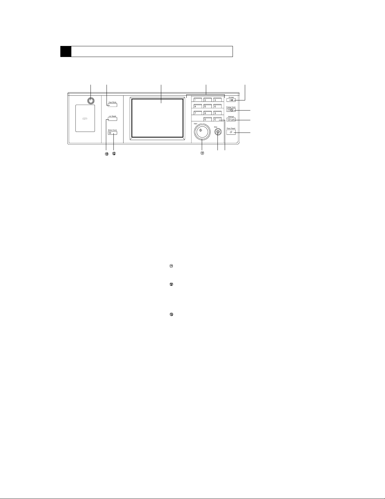
2-1. Control Panel Keys
" # $ %
!
Display Contrast Knob
!
Varies the brightness of the Touch Panel.
D
User Mode Key
"
Changes the screen to the User Mode set-
D
ting screen.
Touch Panel
#
Shows various screens and messages.
D
10-Key Pad
$
Numeric keypad used for entering the
D
number of copies to be made, zoom ratio,
access number, and the Tech. Rep. mode
settings.
Access Mode Key
%
When either “100 Accounts” or “1000 Ac-
D
counts” has been selected for the “Copy
Track” function, the entry of the access
number and the press of this key (Access
Mode) will allow the user to make copies.
Energy Saver Key
&
Sets the copier into the Energy Saver
D
mode.
Interrupt Key
'
Sets the copier into, or lets it leave, the In-
D
terrupt mode.
Panel Reset Key
(
Clears all control panel settings made pre-
D
viously, initializing the copier.
Note: It does not, however, clear the con-
Clear Key
)
Clears the number-of-copies setting, zoom
D
ratio, and counter count.
Stop Key
*
Stops a copy cycle.
D
Start Key
Starts a copy cycle.
D
Mode Check Key
Shows the Mode Check screen, on which
D
the user can check the current copying settings.
Job Recall Key
Selects the Job Recall screen which allows
D
the user to recall or check a copy-job program previously stored in memory.
&
'
(
)*
1149O002EA
tents of the zoom and job program
memory and the settings made immediately before the Interrupt
mode.
S-2
1149SBS0202A
2-2. Explanation of the Touch Panel
1149SBS020201A
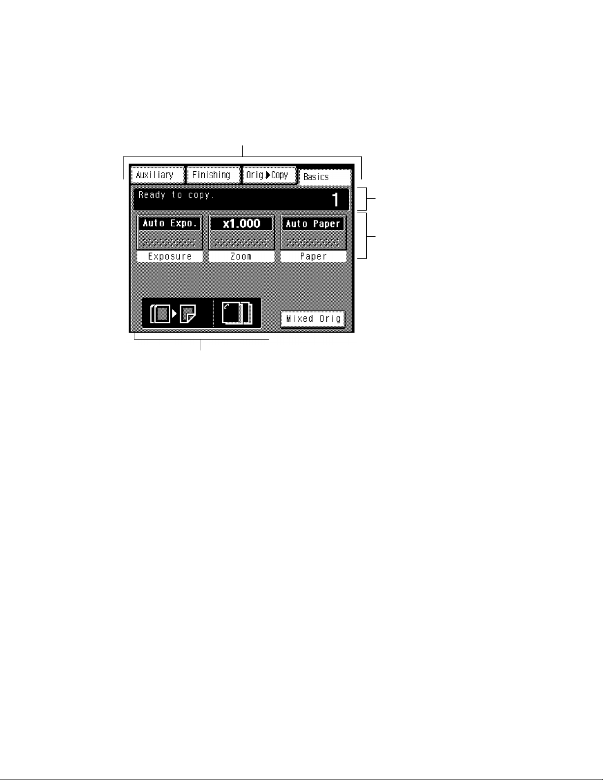
1. Basic Screen
The Basic screen is an initial screen that appears when the copier is turned ON, panel is reset, or when
D
auto clear is activated.
!
1149O263CA
$
Supplementary Function Keys
!
Selects the corresponding menu screen,
D
either Auxiliary, Finishing, or Orig."Copy.
Basic Function Keys
#
Allows the user to select the exposure lev-
D
el, zoom ratio, and copy paper.
"
#
Message Display
"
Shows the current copier status, operating
D
instructions, and other data including the
number of copies selected and the amount
of paper still available for use.
S-3
Function Display
$
Shows graphic representations of the set-
D
tings currently made for Orig."Copy and
Finishing.
1149SBS020202A
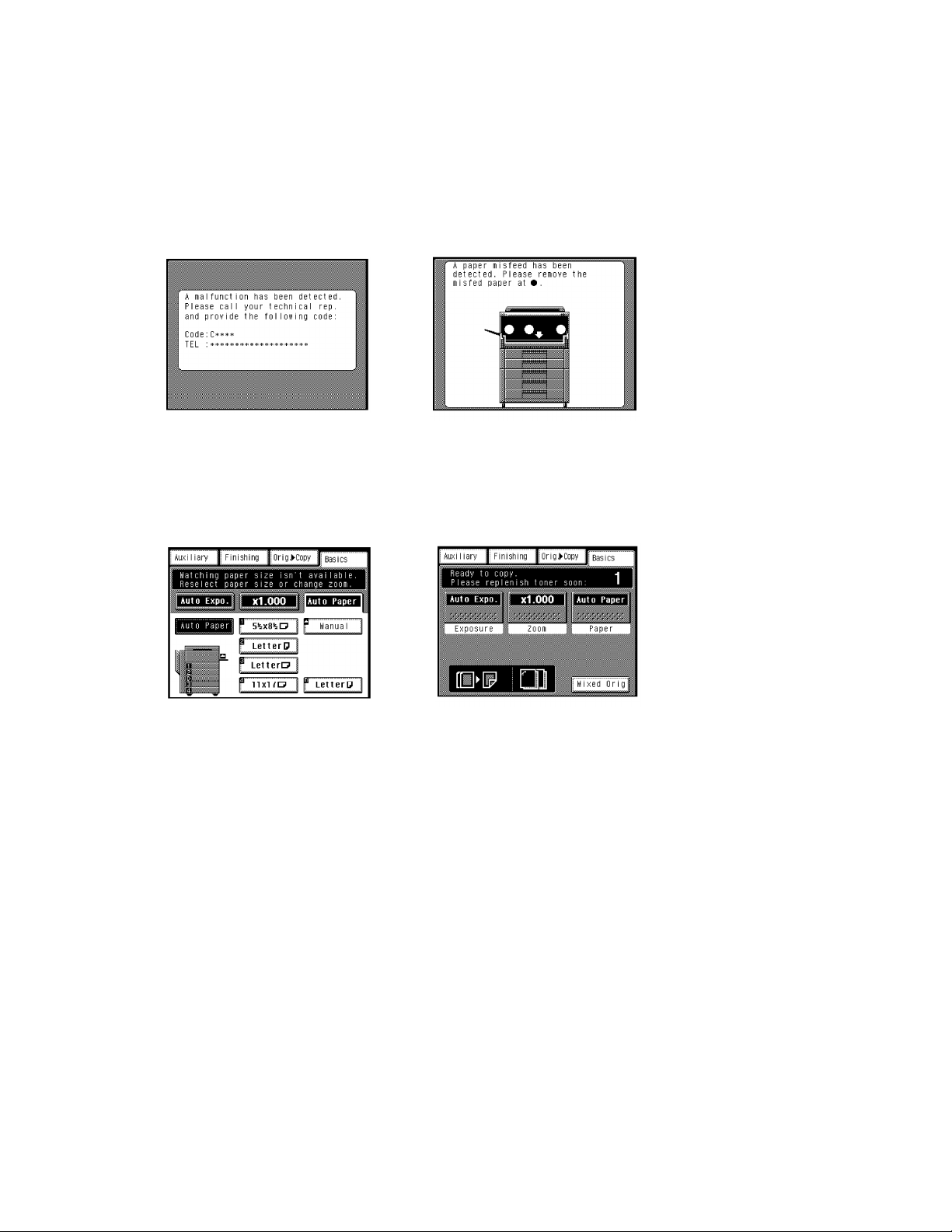
2. Warning Screen
The warning screen may be a malfunction display, error display, warning display, or a caution display.
D
A malfunction display is given when trouble
D
occurs which cannot be corrected by the user.
Example:Malfunction that can be identified
A warning display is given when any further
D
copier operation will not be possible, or only
faulty results will come out, due to erroneous
panel settings or other cause.
<Malfunction Display>
with a specific code.
<Warning Display> <Caution Display>
Example:
Unmatched paper size in Auto Paper
An error display is given when trouble occurs
D
which can be corrected by the user.
Examples: Paper misfeed, toner empty, door
A caution display is given when, though further
D
copier operation will be possible, it could result
in a malfunction.
<Error Display>
open.
1149O387CA1149O421CA
Example:
Toner empty
1149O422CA 1149O385CA
S-4
1151SBS0300A
FUNCTIONS OF SWITCHES AND POINTS ON PWB-I
3
1151SBS0301A
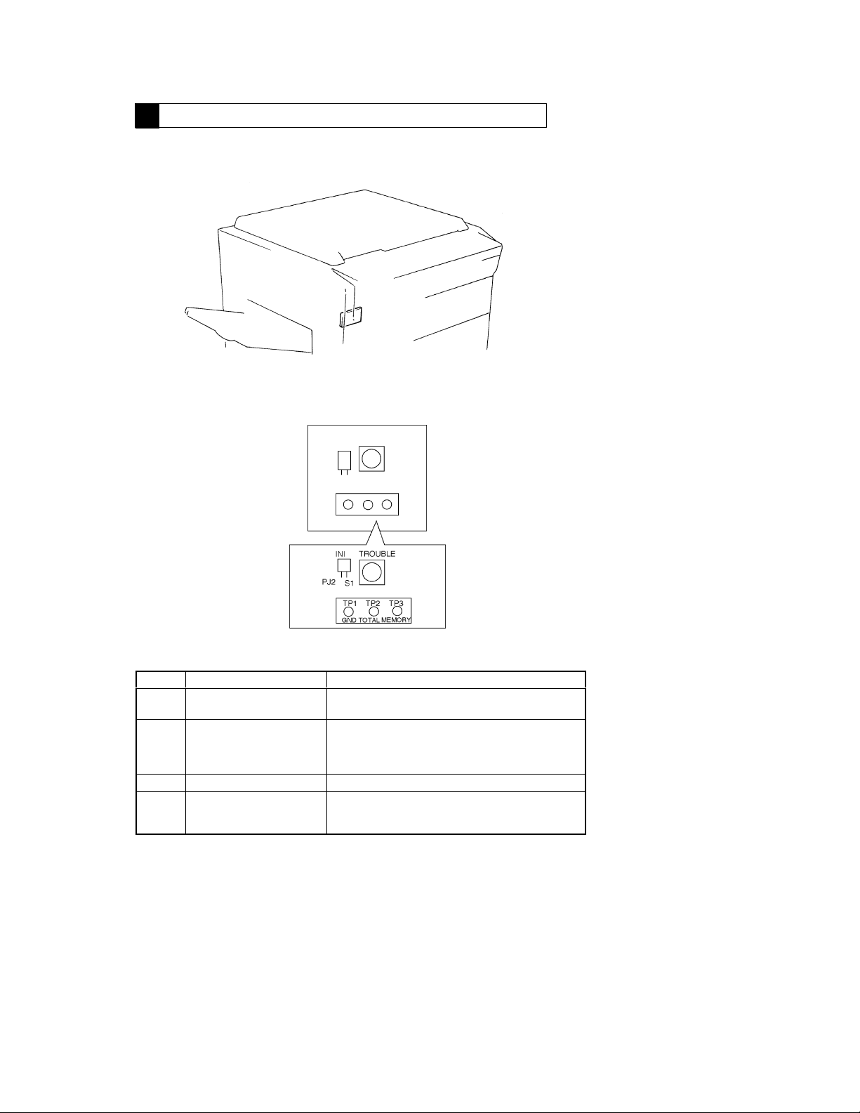
3-1. PWB-I Location
1156SBS0302A
3-2. Tech. Rep. Settings Switches Board PWB-I
1156S001AA
1149S002BB
Symbol Name Description
Trouble Reset Switch Resets a malfunction including those of the Exposure
S1
Initialize Switch Forcibly resets a misfeed or malfunction that occurrs
PJ2
TP1 GND Test Point Ground terminal used for memory clear.
Memory Clear Test Point Initializes all data except the counts of electronic count-
TP3
Lamp (C04XX) and fusing (C05xx).
due to incorrect operation, etc. when it cannot be reset
by opening and closing the Front Door or the press of
S1.
ers, access numbers and administrator number for Copy
Track, and RD mode functions.
S-5
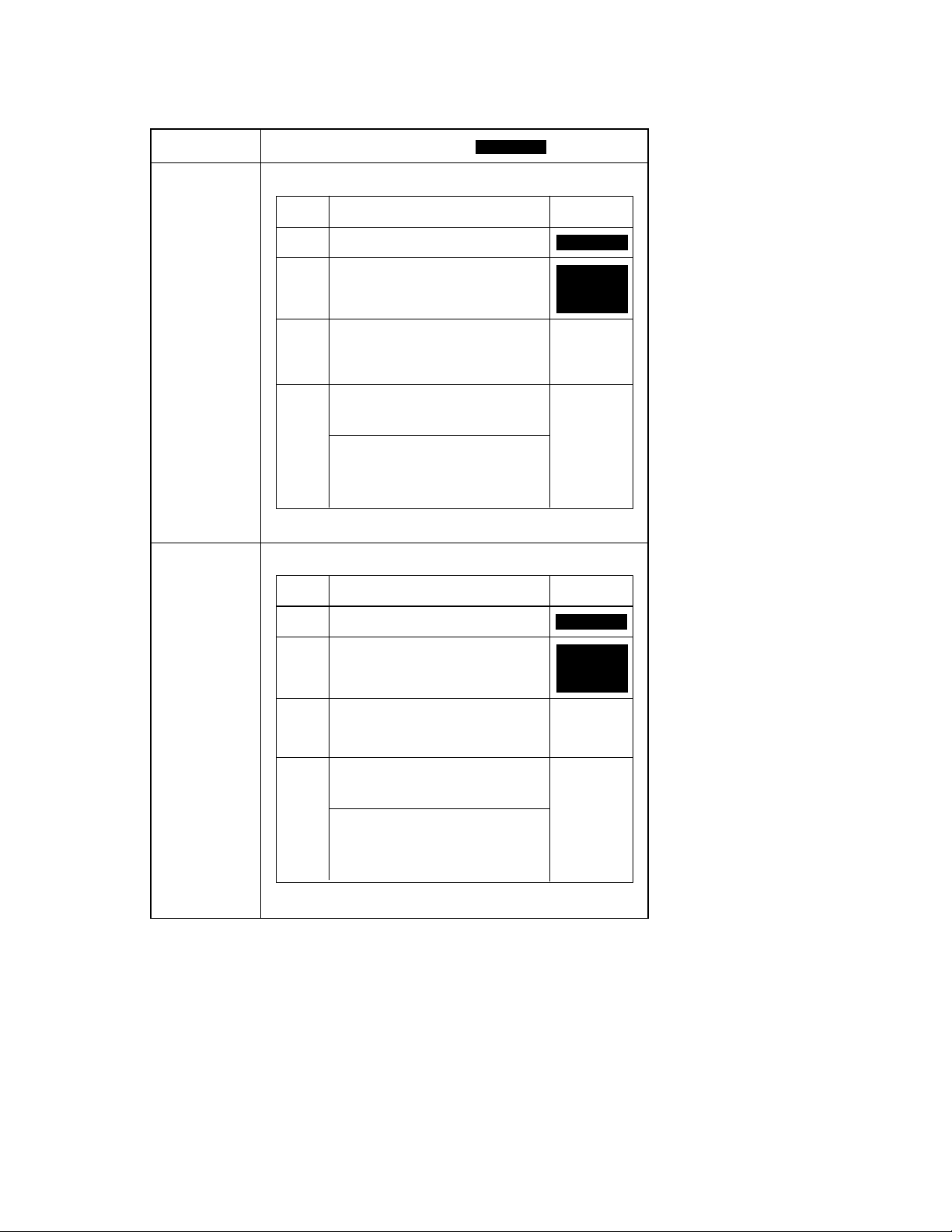
<Clearing Procedures>
C
Initialize Points PJ2
D
1. Turn OFF the Power Switch.
2. With PJ2 closed, turn ON the Power Switch.
3. In approx. 5 sec. open PJ2.
4. Check that the message “Initialize completed” is shown on the Touch Panel, then touch “Enter.”
Memory Clear Test Point TP3
D
1. Turn OFF the Power Switch.
2. With the circuit across TP1 and 3 closed, turn ON the Power Switch.
3. In approx. 5 sec. open the circuit across TP1 and 3.
4. Check that the message “Memory Clear completed” is shown on the Touch Panel, then touch “Enter.”
NOTE
If an erratic operation or display occurs, perform the clearing procedures in the order of PJ2 and TP3.
D
When memory clear has been performed, make the necessary settings again.
D
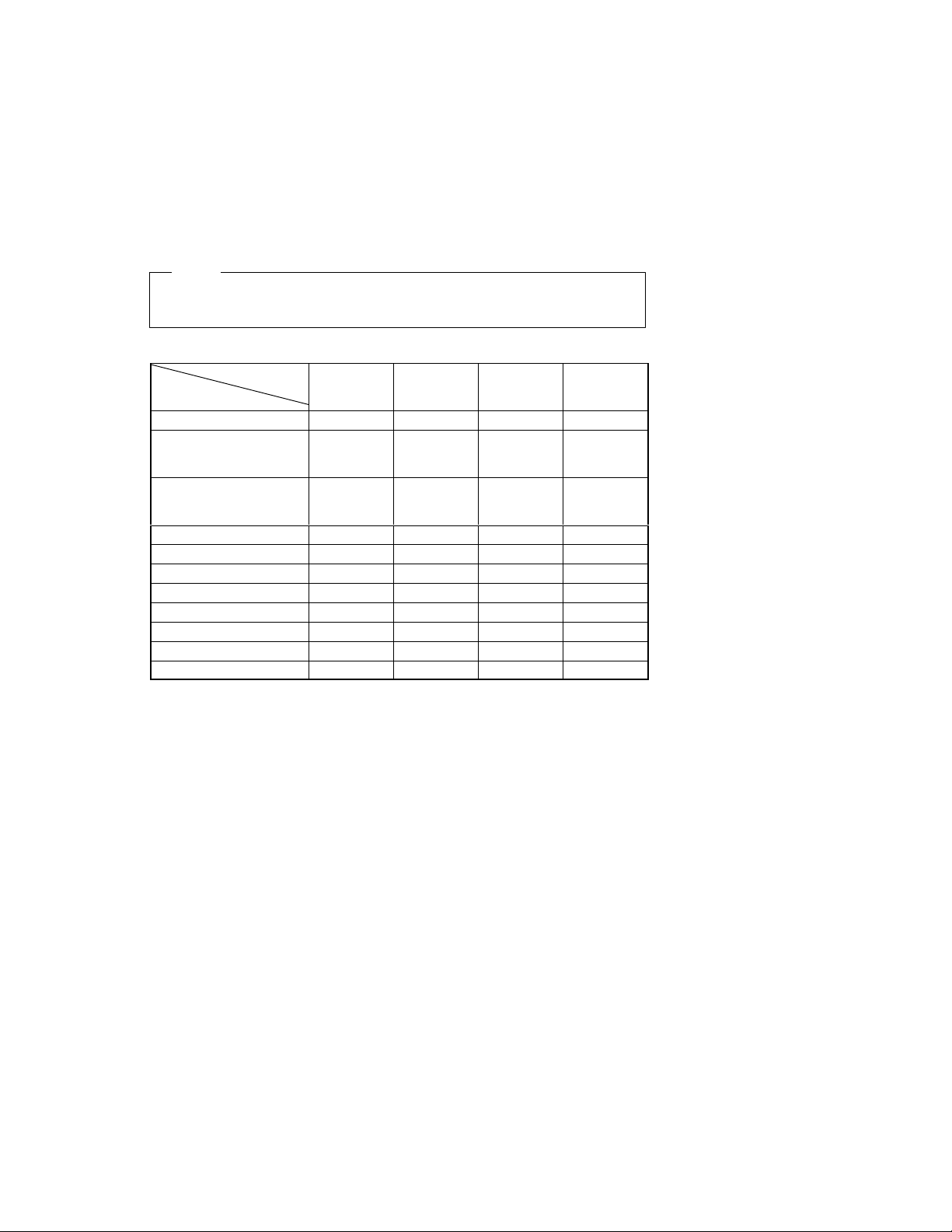
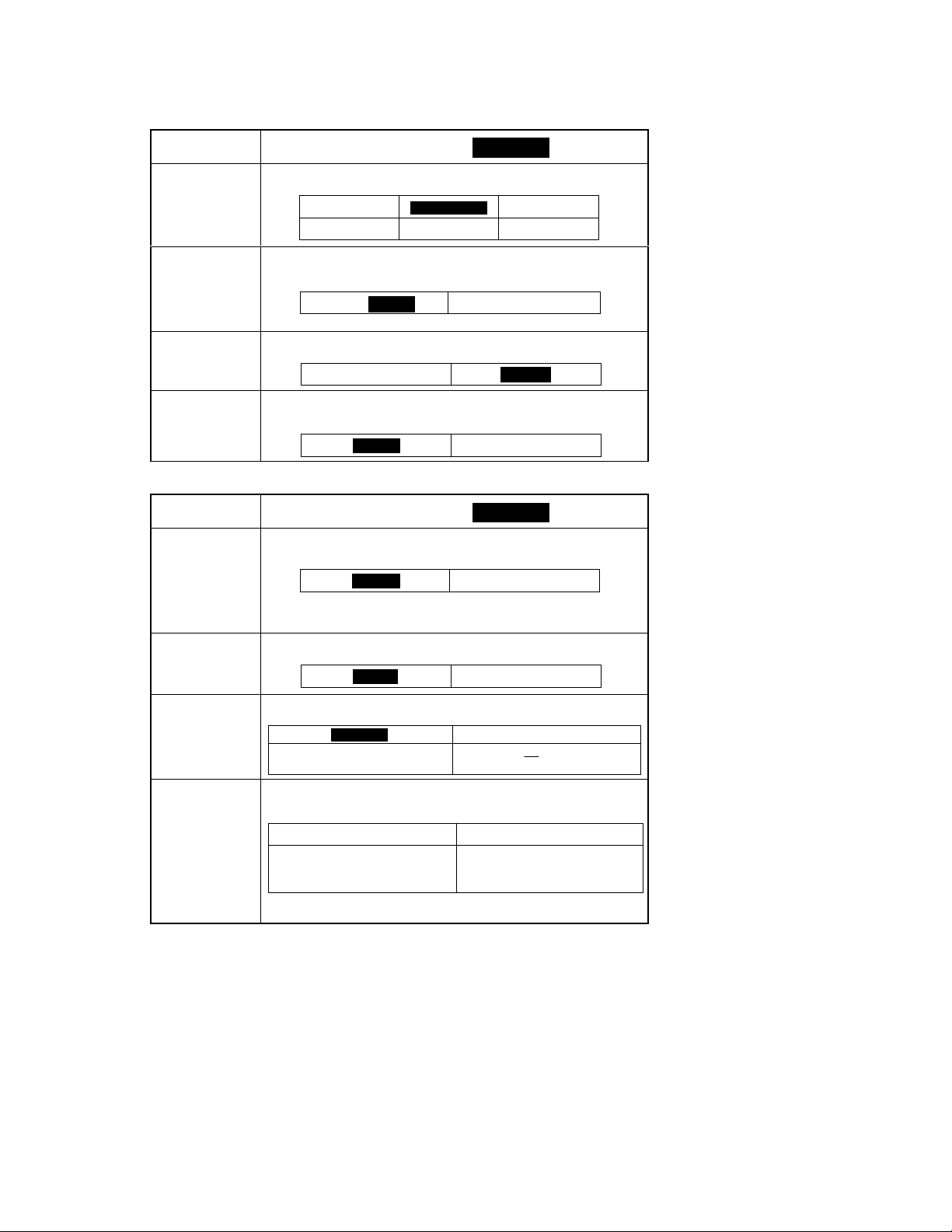
<List of Data Cleared by Switches and Points>
Data Cleared
Misfeed display
Malfunction display (except
Exposure Lamp and fusing
system)
Malfunction display (all including Exposure Lamp and fusing
system)
Erratic operation/display
User mode
Service mode
F5/F7 setting values
System Input
Accessory Test
Level History
Adjust mode
: Cleared (initialized) : Not cleared:
f
learing Method
Front Door
Open/Close
Trouble Reset
Switch
(S1)
f f f f
f f f f
f f f
Initialize
Switch
(PJ2)
f f
Memory Clear
Test Point
(TP3)
f
f
f
f
f
f
f
S-6
1149SBS0400A
USER’S CHOICE MODE4
The User’s Choice mode available through the User Mode menu is used to make various settings ac-
D
cording to the user’s needs.
1149SBS0401A
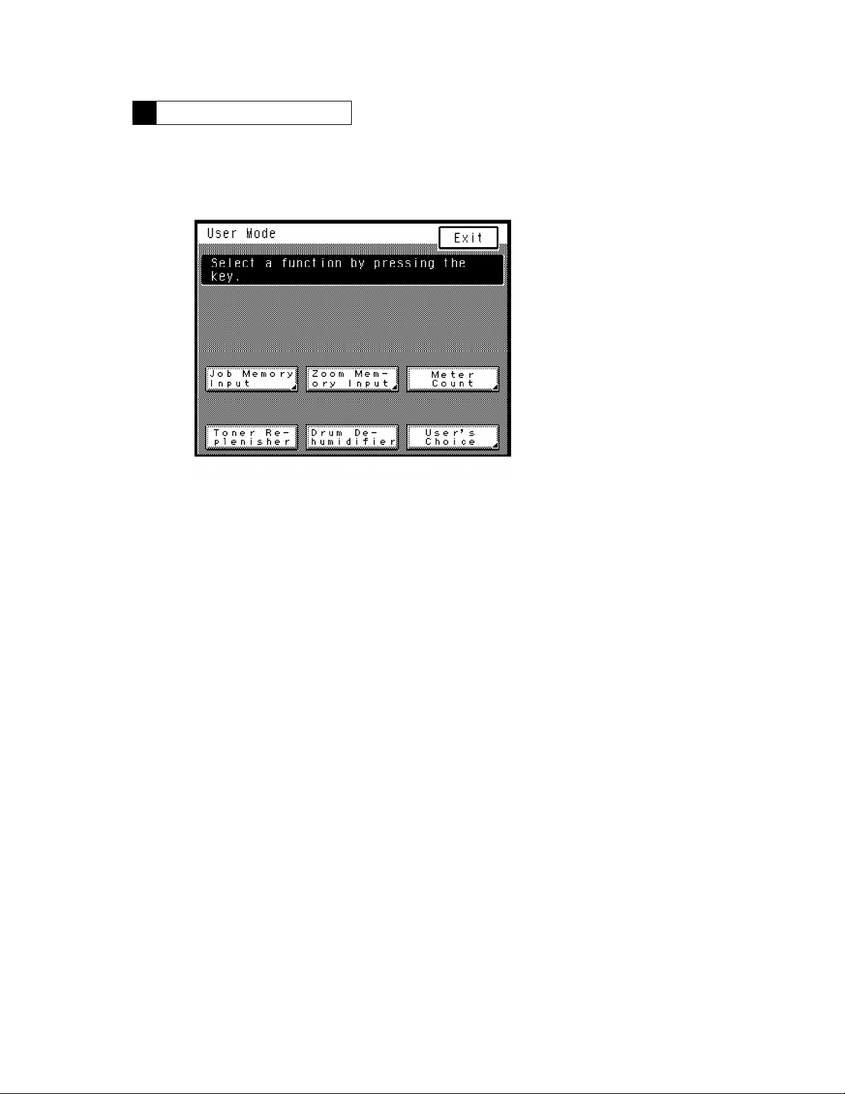
4-1. User’s Choice Selection Screen
1149O262DA
1149SBS0402A
4-2. User’s Choice Function Setting Procedure
<Setting Procedure>
1. Press the User Mode key on the control panel and then touch the “User’s Choice” key.
2. Select the page number key that contains the desired function from among 1/6 through 6/6 shown
at the bottom of the Touch Panel.
3. Select the function to be set and make settings as required.
4. After the settings are complete, touch the “Enter” key to validate the settings.
NOTE:
The function selected is highlighted.
<Exiting the Mode>
Perform any one of the following steps to go back to the Basic screen.
Press the Panel Reset key on the control panel.
D
Touch “Exit” on the Touch Panel.
D
S-7

1156SBS0403A
4-3. User’s Choice Function Tree
Mixed Orig. Detection
User’s Choice
1/6
Language Selection
Paper Priority
Copy Mode Priority
Manual feed expansion
Expo. Mode Priority
Expo. Level Priority
2/6
Manual Expo. Adjust
Finishing Priority
Auto Panel Reset
Energy Saver Mode
3/6
Drum Dehumidifier
Counter Removal
Intelligent Sort
Confirmation Beep
4/6
Original Thickness
5/6
6/6
Smaller Originals
Custom 2in1
Custom 2in1 Separation
Custom Book Copy
Special Paper
Orig."Copy Default
Auto Power-off Mode
Original on Glass
Administrator Mode
S-8
1156SBS0404A
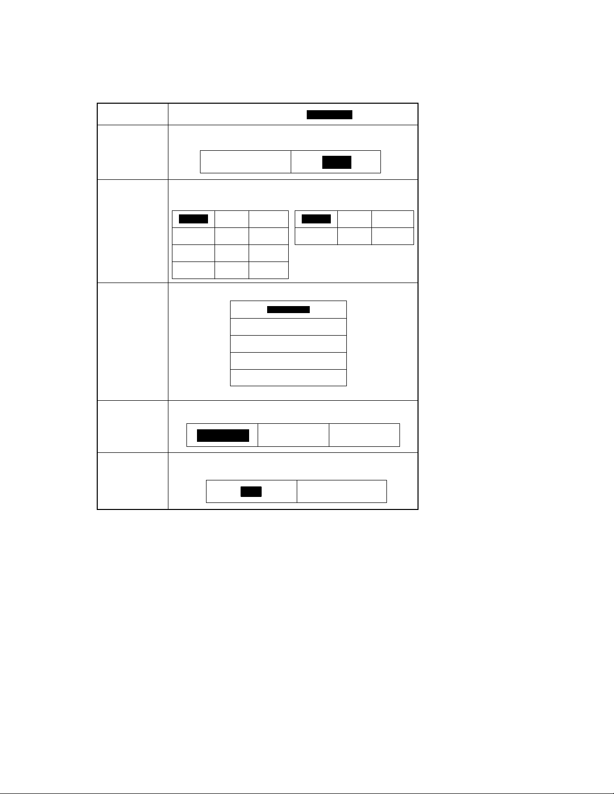
4-4. Settings in the User’s Choice
1156SBS040401A
Touch Panel
Display
Mixed Orig.
Detection
Select whether to enable (“ON”) the Mixed Original Detection mode or not
(“OFF”) when power is turned ON or the Panel Reset key pressed.
Setting (The default is .)
[1/6]
Highlighted
Language Selection
Paper Priority
Copy Mode Priority
ON
Select the language of the Touch Panel messages.
−Metric Areas−
English
Dutch Italian Spanish
Portuguese Danish Norwegian
Saedish Finnish Greek
Specify the paper source selected automatically.
Specify the default mode selected automatically when power is turned ON or
the Panel Reset key pressed.
German
Auto Paper
French
1st Drawer
2nd Drawer
3rd Drawer
4th Drawer
LCT
Auto Size
OFF
−Inch Areas−
English German French
Japanese Chinese Portuguese
Manual
Manual feed
expansion
Select whether to use Manual feed expansion (“ON”) when using the Multi Bypass
Tray or not (“OFF”)
ON
OFF
S-9
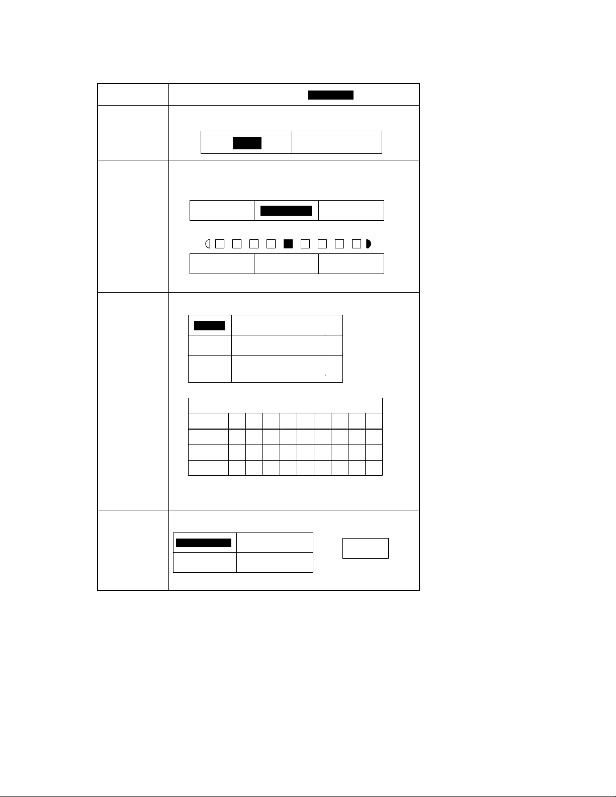
1156SBS040402A
Touch Panel
Display
Expo. Mode Priority Specify the default exposure mode selected automatically when power is turned
ON or the Panel Reset key pressed.
[2/6]
Setting (The default is .)
Highlighted
Auto
Expo. Level Priority Auto: Select the default exposure level in the Auto Exposure mode.
Manual Expo.
Adjust
Manual: Set the default exposure level in the Manual Exposure mode.
<Auto Exposure>
Lighter Darker
Lighter Darker
NOTE: EXP. 1 (Lighter) to EXP. 9 (Darker)
Determine the default voltage curve (EXP. level) in the Manual Exposure mode,
as optimized by the type of original.
Mode 1 Halftone images, photos
Mode 2 Ordinary originals
Mode 3 Originals with a colored back-
EXP.
Mode 1
Mode 2
Mode 3
ground or faint texts
<Manual Exposure Voltages in Different Modes>
Manual Exposure Voltage (V)
123456789
+8
+8
+8
Normal
<Manual Exposure>
Normal
+5 +2 +1 0 −1 −2 −5 −8
+6 +4 +2 0 −2 −4 −6 −8
+7 +6 +3 0 −3 −6 −7 −8
Manual
NOTE: EXP. 5 uses as reference the voltage value automatically adjusted by
the F5 operation.
Finishing Priority Select the default finishing type when the copier is equipped with a Sorter or Sta-
ple Sorter.
Non Sort Group
Sort Sort Staple
Hole Punch
+
NOTE: Hole Punch can be
combined with any one
of the left functions.
S-10
1156SBS040403A
Touch Panel
Display
Auto Panel Reset Specify the default exposure mode selected automatically when power is turned
ON or the Panel Reset key pressed.
30 sec. 2 min.
3 min. No Reset
[3/6]
Setting (The default is .)
1 min.
5 min.
Highlighted
Energy Saver Mode Set the time it takes the copier to enter the Energy Saver mode after a copy cycle
Drum Dehumidifier Select whether to allow the copier to enter the Drum Dehumidifier mode automat-
Counter Removal Select whether to reset the panel or not when the Plug-In Counter is pulled out
1156SBS040404A
Touch Panel
Display
Intelligent Sort
Confirmation Beep Select whether to turn “ON” or “OFF” the beep that sounds each time a key on
Original Thickness Select whether to allow (“Thin”) the user to make copies from thin originals in
Smaller Originals Select whether to enable (“ON”) a copy cycle or not (“OFF”) when it is initiated
has been completed or the last key operated. Use the 10-Key Pad to set the time
(1 to 120 min.).
1 to 120 (15 min.) OFF
NOTE: The OFF setting is available for European areas only.
ically after it has been turned ON, or not.
ON OFF
of the copier, a magnetic card is pulled out of the Data Controller, or the Access
Mode key is pressed.
ON OFF
[4/6]
Setting (The default is .)
Select whether to turn “ON” or “OFF” the function that automatically switches between Sort and Non-Sort according to the number of originals loaded in the document feeder.
ON OFF
NOTE: This function is enabled when “Mixed Orig. Detection” is
turned “OFF” and the copier is in the Auto Paper or Auto
Size mode.
the control panel is pressed or that on the Touch Panel is touched.
ON OFF
addition to the standard ones or not (“Standard”) using the document feeder.
The orginal is pressed against the
Original Width Scale when stopped.
by pressing the Start key with an original of the smallest detectable size (metric
areas: A5 or smaller; inch areas: Letter or smaller) placed on the Original Glass.
The copy cycle is run using the paper
loaded in the default paper source.
NOTE: The default setting is OFF for the metric areas and ON for the inch
Standard Thin
areas.
Highlighted
The original is not pressed against the
Original Width Scale when stopped.
OFFON
A warning message is given and the
copier inhibits the start of this copy
cycle.
S-11
1156SBS040405A
Touch Panel
Display
Custom 2in1 Make the settings for “Paper,” “Zoom,” “Margin,” and “Erase” that are automati-
cally recalled when 2
Function Initial SettingDescription
[5/6]
Setting (The default is .)
-
in-1 copy is selected.
Highlighted
Custom 2in1
Separation
Paper Auto Paper, sizes of paper loaded in drawers
Zoom Auto Size, fixed zoom ratios
Position: Right edge, left edge
Margin
NOTE: The erase width for the Top Edge and for the CD direction of the
Make the settings for “Paper,” “Zoom,” “Margin,” and “Erase” that are automatically recalled when 2-in-1 separation copy is selected.
Function Initial SettingDescription
Margin
NOTE: The erase width for the Top Edge and for the CD direction of the Frame
Mode: Shift-for-Margin, Margin-by-Reduc-
tion
Width: Metric areas − 5, 10, 15, 20 mm
Inch areas − 1/4, 1/2, 3/4, 1”
Position: Right Edge, Left Edge, Frame, Top
Edge, Center, Frame+Center
Width: Metric areas − 5, 10, 15, 20 mm
Inch areas − 1/4, 1/2, 3/4, 1”
Make the following selections only when
Erase
Frame+Center is selected.
Frame: Metric areas − 5, 10, 15, 20 mm
Inch areas − 1/4, 1/2, 3/4, 1”
Center: Metric areas − 5, 10, 15, 20 mm
Inch areas − 1/4, 1/2, 3/4, 1”
Frame is only 10mm for the metric areas and 1/2” for the inch areas.
Paper Auto Paper, sizes of paper loaded in drawers
Zoom Auto Size, fixed zoom ratios
Position: Right edge, left edge
Mode: Shift-for-Margin, Margin-by-Reduc-
tion
Width: Metric areas − 5, 10, 15, 20 mm
Inch areas − 1/4, 1/2, 3/4, 1”
Position: Right Edge, Left Edge, Frame, Top
Edge, Center, Frame+Center
Width: Metric areas − 5, 10, 15, 20 mm
Inch areas − 1/4, 1/2, 3/4, 1”
Make the following selections only when
Erase No erase
Frame+Center is selected.
Frame: Metric areas − 5, 10, 15, 20 mm
Inch areas − 1/4, 1/2, 3/4, 1”
Center: Metric areas − 5, 10, 15, 20 mm
Inch areas − 1/4, 1/2, 3/4, 1”
is only 10mm for the metric areas and 1/2” for the inch areas.
Auto Paper
Metric areas:
X0.707
Inch areas:
X0.647
No margin
No erase
1st Drawer
Metric areas:
X1.414
Inch areas:
X1.294
No margin
S-12
 Loading...