

Page 1

NON-CONTACT 3D DIGITIZER
VIVID 9i/VI-9i
Instruction Manual (HARDWARE)
NOTE
The VI-9i is mo
Please note that the VIVID 9i model name is intended only for reference with this manual.
del name for Europe and the VIVID 9i is model name for other countries.
Page 2
Safety Symbols
The following symbols are used in this manual to prevent accidents which may occur as result of incorrect use
of the instrument.
Denotes a sentence regarding safety warning or note.
Read the sentence carefully to ensure safe and correct use.
Denotes a prohibited operation.
The operation must never been performed.
Denotes an instruction.
The instruction must be strictly adhered to.
Denotes an instruction.
Disconnect the AC power cord from the AC outlet.
Denotes a prohibited operation.
The part must never be disassembled.
Denotes an instruction.
Connect the grounding terminal as instructed.
Denotes a sentence regarding safety precaution for laser.
Read the sentence carefully to ensure safe and correct use.
Notes on this Manual
• Copying or reproduction of all or any part of the contents of this manual without KONICA MINOLTA
SENSING’s permission is strictly prohibited.
• The contents of this manual are subject to change without prior notice.
• Every effort has been made in the preparation of this manual to ensure the accuracy of its contents. However,
should you have any questions or find any errors, please contact a KONICA MINOLTA SENSING-authorized service facility.
• KONICA MINOLTA SENSING will not accept any responsibility for consequences arising from the use of
the instrument.
• Company names and product names which appear in this manual are their trademarks or registered trademarks.
• Contents and display examples given in this manual are subject to change.
About This Manual and Related Documents
The VIVID 9i Non-Contact 3D Digitizer offers rapid, high-precision 3D scanning ideal for imaging of industrial products in a wide range of shapes and configurations. This manual describes the digitizer’s features and
operating procedures, and calls attention to relevant precautions.
Please also refer to documents listed below for related information.
Document Content
Polygon Editing Tool
Instruction Manual
Polygon Editing Tool
Basic Operations Guide
Photogrammetry System
PSC-1 Instruction Manual
Explains how to install and use the Polygon Editing software, and gives details
about all of the software’s features. The Polygon Editing Tool software can be
used to control the operation of VIVID non-contact 3D digitizers, to convert
scanned data into polygon data, to edit and process the scanned data, and to save
the data into standard formats.
Explains the basic operations of the Polygon Editing Tool software, with reference to the VIVID 910 digitizer.
Explains the PSC-1 system, a high-precision alignment system based on photographic measurement technology. This system is for use in the VIVID 9i only.
Page 3
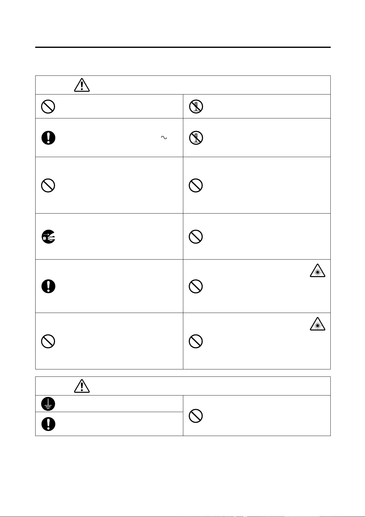
Safety Precautions
When using this hardware, the following points must be strictly observed to ensure correct and safe use.
After you have read this manual, keep it in a safe place so that it can be referred to easily whenever it is needed.
WARNING
Do not use the VIVID 9i in places where flammable or combustible gases (gasoline etc.) are
present. Doing so may cause a fire.
Always use the AC power cord supplied as a
standard accessory with the VIVID 9i, and connect it to an AC outlet (100-240 V , 5060 Hz). Failure to do so may damage the VIVID
9i, causing a fire or electric shock.
Do not bend, twist or pull the AC power cord excessively. In addition, do not place heavy items
on the AC power cord, or damage or modify it in
any way. Doing so may cause damage to the AC
power cord, resulting in fire or electric shock.
If the VIVID 9i will not be used for a long time,
disconnect the AC power cord from the AC outlet. Accumulated dirt or water on the prongs of
the AC power cord’s plug may cause a fire. If
there is any dirt or water on the prongs of the AC
power cord’s plug, remove it.
When disconnecting the AC power cord’s plug,
always hold the plug and pull it to remove it.
Never pull the AC power cord itself. Doing so
may damage the AC power cord, causing a fire
or electric shock. In addition, do not insert or
disconnect the AC power cord’s plug with wet
hands. Doing so may cause electric shock.
The VIVID 9i should not be operated if it is
damaged, or smoke or odd smells are detected.
Doing so may result in a fire. In such situations,
turn the power OFF immediately, disconnect the
AC power cord from the AC outlet, and contact
the nearest KONICA MINOLTA SENSING-authorized service facility.
Failure to adhere to the following points may result
in death or serious injury.
Do not disassemble or modify the VIVID 9i.
Doing so may cause a fire or electric shock.
Do not remove the cover as doing so may cause
electric shocks.
Take special care not to allow liquid or metal objects to enter the VIVID 9i. Doing so may cause
a fire or electric shock. Should liquid or metal
objects enter the VIVID 9i, turn the power OFF
immediately, disconnect the AC power cord
from the AC outlet, and contact the nearest
KONICA MINOLTA SENSING-authorized
service facility.
The VIVID 9i should not be operated if dirt or
dust has entered through the vent holes. Doing
so may result in a fire. For periodic inspection,
contact the nearest KONICA MINOLTA SENSING-authorized service facility.
Never stare into the laser emitting
window.
Do not place a lens, mirror or optical
element in the passage of the laser
beam. Doing so may converge the laser beam, resulting in damage to your
eyes, burns or fire. To prevent the
above accidents, make sure that a wall
or similar which can block the laser
beam is located behind the object.
CAUTION
Be sure to connect the AC power cord’s plug to
an AC outlet that has a grounding terminal.
Make sure that the AC outlet is located near the
VIVID 9i and that the AC power cord’s plug can
be easily connected and disconnected.
Falling to adhere to the following points may result in
injury or damage to the instrument or other property.
Do not place the instrument on an unstable or
sloping surface. Doing so may result in its dropping or overturning, causing injury. Take care
not to drop the instrument when carrying it.
1
Page 4
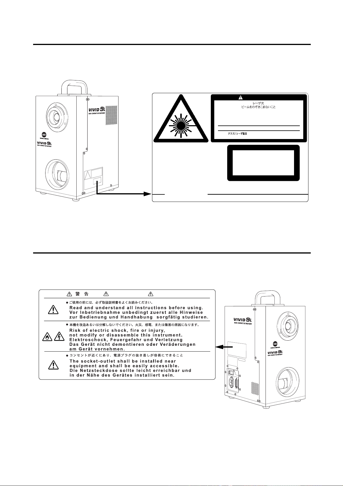
Laser Caution and Identification Label
Laser Caution and Identification Label
AVOID EXPOSURE
Laser radiation is emitted
from this aperture.
KONICA MINOLTA SENSING, INC. 3-91, Daisennishimachi, Sakai, Osaka 590-8551, Japan
manufactured
CAUTION
LASER RADIATION
DO NOT STARE INTO BEAM
LASER STRAHLUNG
NICHT IN DEN STRAHL SEHEN
MAX 30mW 690nm
Complied with IEC Publication 60825-1:1993, Amendment-2:2001
CLASS 2 LASER PRODUCT
CLASS 1 LASER PRODUCT
Complies with 21 CFR Chapter 1. Subchopter J.
Warning Label
WARNING WARNUNG
2
Page 5

Notes On Use
• The VIVID 9i is designed for indoor use only, and should never be used outside.
• This digitized has been calibrated at 20°C. We recommend that you use it environments where ambient temperature is 20°C (68°F).
• Use an AC power source which is within ±10% of the rated voltage.
• The VIVID 9i should be used within a temperature range of 10 to 40°C at a relative humidity of 65% or less.
• Do not use the VIVID 9i in direct sunlight or near sources of heat such as stoves. Doing so will cause the
temperature of the VIVID 9i to rise considerably higher than room temperature and may result in malfunctions. Use the VIVID 9i in a well ventilated area and make sure that the ventilation holes of the VIVID 9i are
not blocked.
• Do not use the VIVID 9i in extremely dusty or humid areas. Doing so may result in malfunctions.
• Do not subject the VIVID 9i to strong vibration or shocks. Doing so may result in malfunctions.
• When using the VIVID 9i on upper floors of buildings or near high-traffic streets, the instrument and/or
measurement subject may vibrate, adversely affecting measurement results.
• Do not allow the digitizer to fall on its side, as it may sustain damaged if knocked over.
• Do not disconnect cords and cables with the POWER switch of the VIVID 9i set to ON “I”. Doing so may
result in malfunctions.
• The VIVID 9i has been tested and found to comply with the limits for a Class A digital device, pursuant to
Part 15 of the FCC Rules. These limits are designed to provide reasonable protection against harmful interference when the equipment is operated in a commercial environment. This equipment generates, uses, and
can radiate radio frequency energy and, if not installed and used in accordance with the instruction manual,
may cause harmful interference to radio communications. Operation of this equipment in a residential area is
likely to cause harmful interference in which case the user will be required to correct the interference at his
own expense.
• The VIVID 9i is a class II instrument specified in IEC Publication 825. Use it according to the instructions
given in this manual.
• Do not use the VIVID 9i at altitudes of higher than 2000 m.
• Before using this unit for the first time, and before reusing it following transport, check that the lens is securely in place. If the lens is loose, tighten it in accordance with the tightening instructions included in the
lens replacement procedure.
Care On Storage
• The VIVID 9i should be stored in areas with temperatures of between 0 and +40°C. Do not store it in areas
subject to high temperature or high humidity or where sudden changes in temperature or condensation are
likely to occur. We recommend storing the VIVID 9i around room temperature (20
(silica gel etc.).
• Do not leave the VIVID 9i inside a closed car or in the trunk of a car. Under direct sunlight, the increase in
temperature can be extreme and may result in malfunctions.
• The VIVID 9i should not be stored in areas where there is an excessive amount of dust, cigarette smoke or
chemical gas. Failure to adhere to this may result in performance degradation or break-down.
• When shipping the product, use the original packing materials in which the product was shipped. The materials will provide protection against vibrations and impact, and also provide some protection against sudden
changes in temperature.
• Lenses that are not in use should be capped and kept in the lens case.
• Before storing this equipment, be sure to attach the receiving lens cap and the laser barrier.
± 3°C) with a desiccant
3
Page 6

Notes On Cleaning
• If the VIVID 9i needs cleaning, wipe with a soft dry cloth. Never use solvents such as thinner or benzene.
• If the lens or laser emitting window is soiled with sand or dust, blow off the dirt using a blower, and wipe
them gently with a piece of cleaning paper dampened with cleaning agent.
• In cases of malfunction, do not disassemble the VIVID 9i or attempt to repair it yourself. Contact the nearest
KONICA MINOLTA SENSING-authorized service facility.
Notes On Maintenance
To maintain the accuracy of the high-precision Galvano mirror, that plays the most important role in measurement accuracy, a drying agent is used inside the VIVID 9i. Normally, the dehumidification effect of the drying
agent lasts more than one year. However, its life varies with the operating and storage environment.
To maintain the designed performance of the VIVID 9i, you are recommended to replace the drying agent once
a year. Contact the nearest KONICA MINOLTA SENSING-authorized service facility.
4
Page 7

Contents
Safety Precautions........................................................................................................................................................................ 1
Laser Caution and Identification Label........................................................................................................................................ 2
Warning Label.............................................................................................................................................................................. 2
Notes On Use ............................................................................................................................................................................... 3
Care On Storage ........................................................................................................................................................................... 3
Notes On Cleaning ....................................................................................................................................................................... 4
Notes On Maintenance................................................................................................................................................................. 4
Chapter 1 Before Using the Instrument
Package Contents (Standard Accessories) ........................................................................................................................................... 8
Optional Accessories............................................................................................................................................................................. 10
System Configuration........................................................................................................................................................................... 11
Names and Functions of Parts............................................................................................................................................................. 12
Main Body.................................................................................................................................................................................. 12
Operation Panel.......................................................................................................................................................................... 13
Chapter 2 Preparation
Connecting the AC Power Cord.......................................................................................................................................................... 16
Connecting the VIVID 9i to a Computer............................................................................................................................................ 17
Setting the SCSI ID No. ............................................................................................................................................................. 18
Setting the Terminator ............................................................................................................................................................... 19
Starting and Quitting ........................................................................................................................................................................... 21
Starting the VIVID 9i................................................................................................................................................................. 21
Quitting the VIVID 9i ................................................................................................................................................................ 23
Mounting to the Tripod........................................................................................................................................................................ 24
Chapter 3 Operation
Replacing the Lens and Field Calibration .......................................................................................................................................... 28
Relationship between Measurement Distance and Object ......................................................................................................... 28
Replacing Procedure .................................................................................................................................................................. 29
Field Calibration................................................................................................................................................................................... 32
Field Calibration System............................................................................................................................................................ 32
Executing Field Calibration ....................................................................................................................................................... 34
Adjusting the White Balance............................................................................................................................................................... 42
Displaying the Status Information ...................................................................................................................................................... 44
Adjusting the Laser Power and CCD Gain Manually ...................................................................................................................... 45
Setting the Scan Mode .......................................................................................................................................................................... 46
Chapter 4 Appendix
Error Messages ..................................................................................................................................................................................... 48
Explanation of Measuring Principle................................................................................................................................................... 49
Measuring Principle ................................................................................................................................................................... 49
High-Speed Image Processing Circuit ....................................................................................................................................... 50
Time center of gravity and Space center of gravity ................................................................................................................... 50
Dimension Diagram.............................................................................................................................................................................. 51
Specifications......................................................................................................................................................................................... 52
5
Page 8

6
Page 9

Chapter 1
Before Using the Instrument
7
Page 10
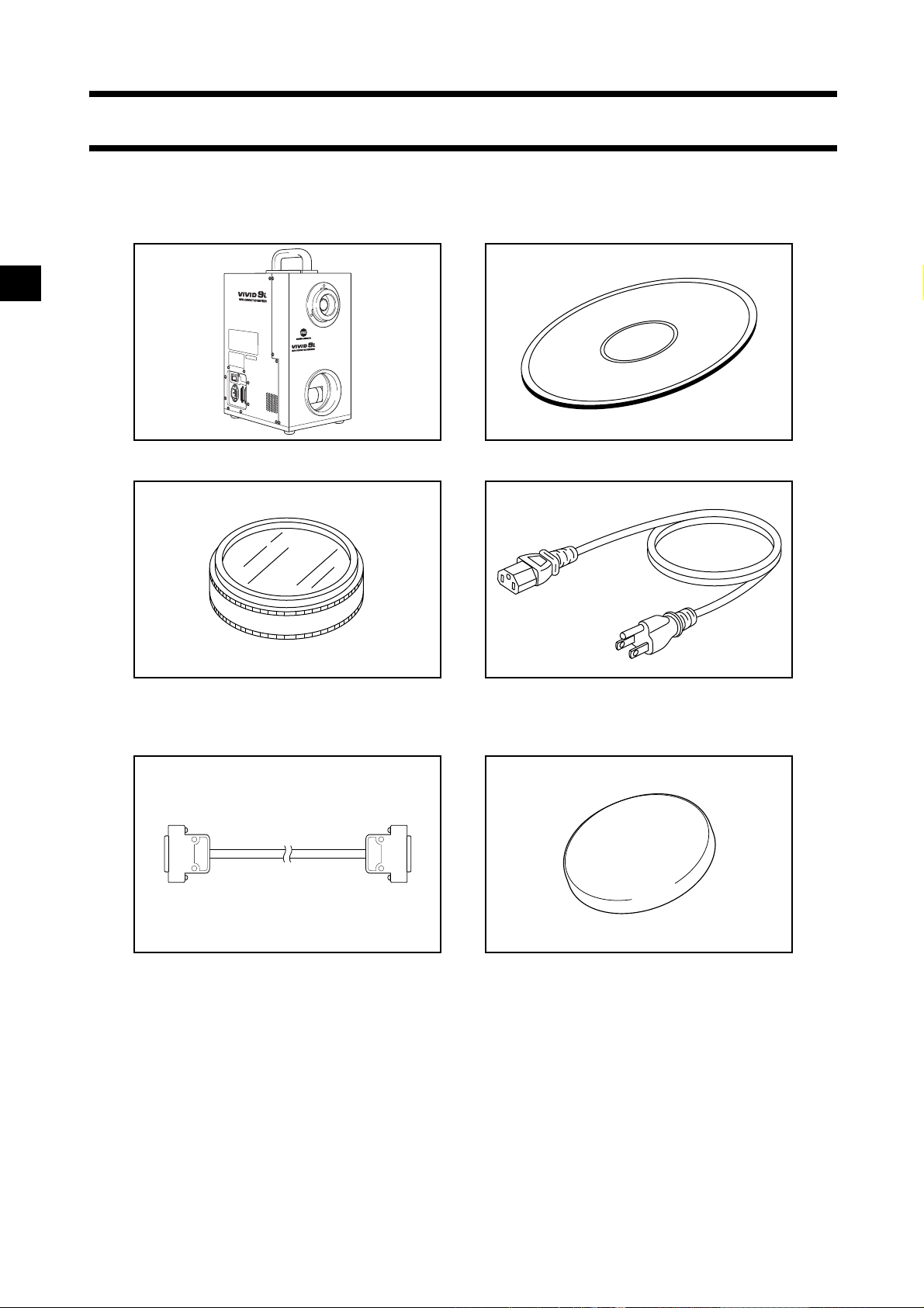
Package Contents (Standard Accessories)
Check that the following standard accessories are present.
VIVID 9i Main Body Polygon Editing Tool
(with USB protect key)
White Balance Cap VI-A10 AC Power Cord
SCSI Cable VI-A20 Laser Barrier
(Half-pitch, D-sub, 50-pin male plug
– 50-pin male plug)
8
Page 11
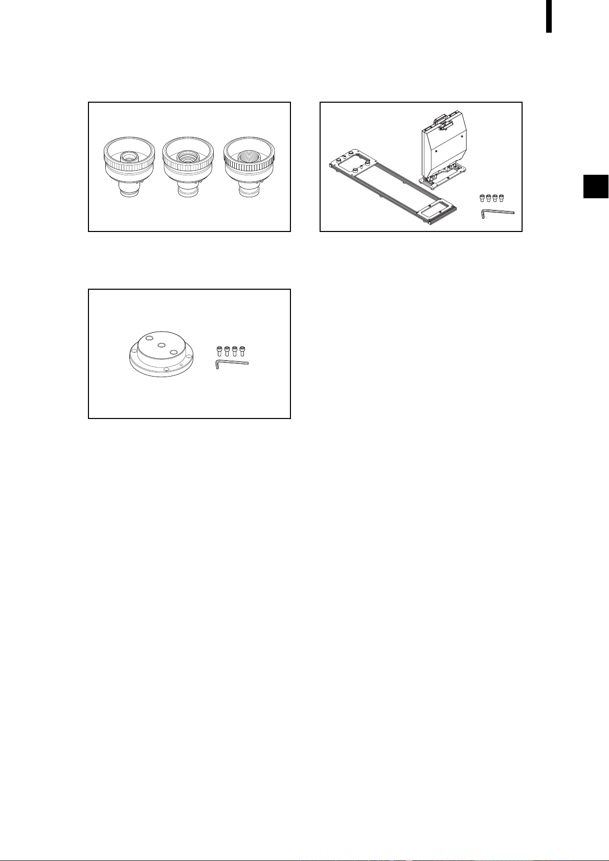
Package Contents (Standard Accessories)
Lens Field Calibration System
(3 types, TELE, MIDDLE, WIDE/ (Field Calibration System, Frame for Calibration
with Lens Cap) System, Hex wrench (M5), 4 screws)
Tripod Attachment Set
(Tripod attachment, Hex wrench (M3), 4
screws)
9
Page 12
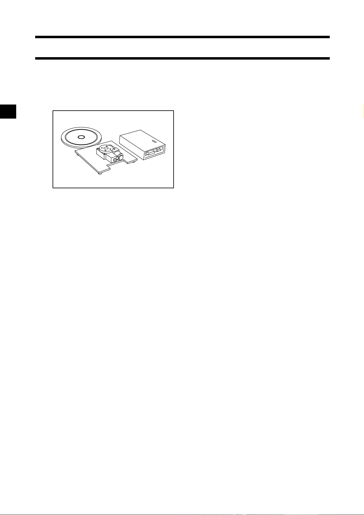
Optional Accessories
When you need to purchase the following optional items, contact a KONICA MINOLTA SENSING-authorized service facility.
Rotary Stage Set Tripod/Panhead VI-B25
(Pan head, Tripod, Ball Adapter)
10
Page 13

System Configuration
Standard Accessories
Optional Accessories
(A commercially available computer can be used)
AC Power Cord
VIVID 9i Main Body
Tripod Attachment Set
Tripod/Panhead
VI-B25
White Balance Cap
VI-A10
Polygon Editing Tool
SCSI Cable VI-A20
Computer
Laser Barrier
3 types of lens
Field Calibration System Rotary Stage Set
11
Page 14
Names and Functions of Parts
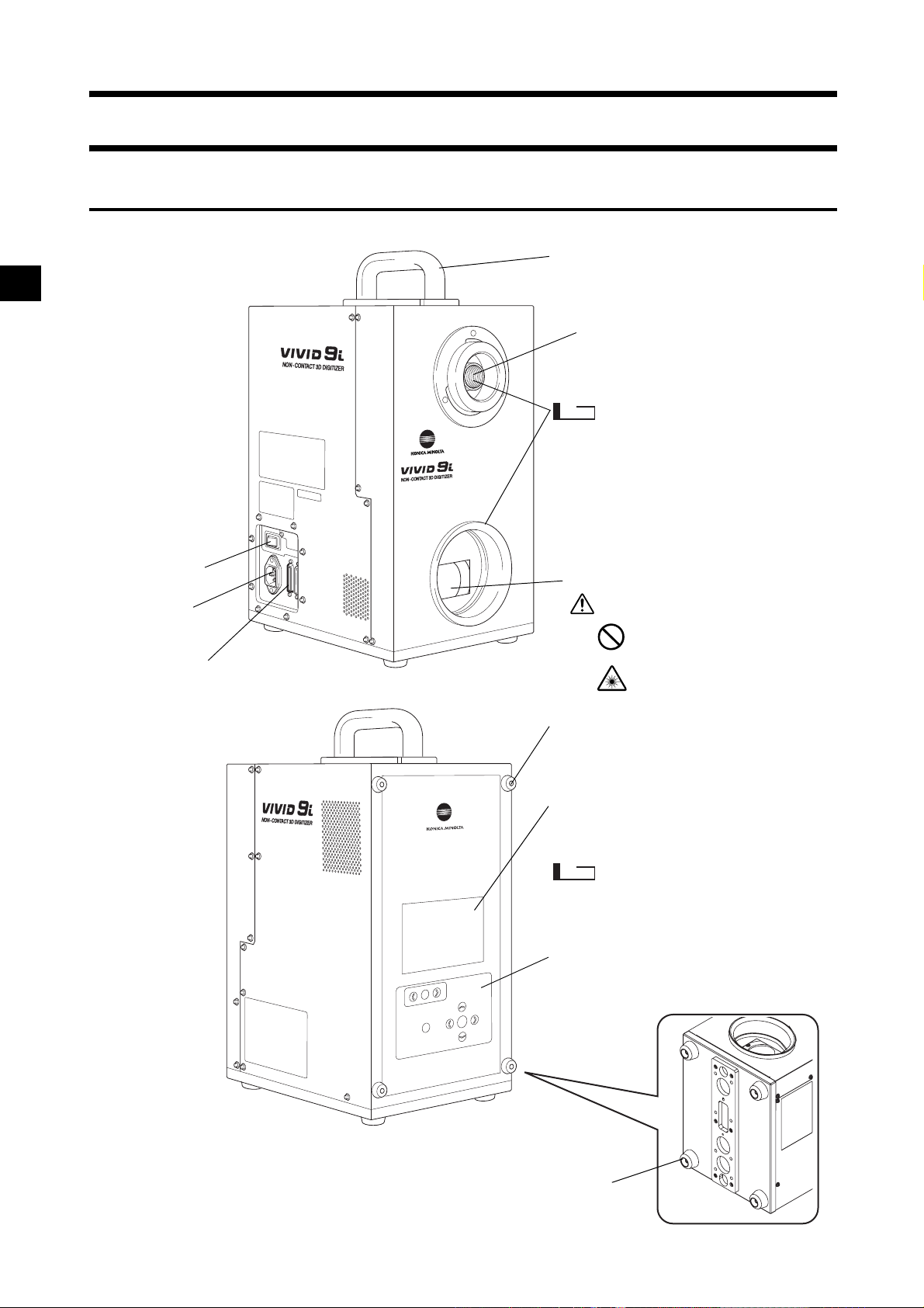
Main Body
Handle
Note
Power Switch
AC Power
Connector
SCSI Port
Laser Emitting Window
Light-Receiving Lens
Please keep the receiving
lens cap and the laser barrier place in place when you
are not carrying out scanning. Dust and scratches on
the laser and lens can adversely affect scanning precision.
WARNING
A laser beam is emitted from this window.
Do not stare into this
window.
Rubber supports
Use when necessary to lean the device
on its side for installing the tripod attachment, etc.
Viewfinder (5.7" LCD)
Displays the lens image and various setup menus.
Note
In rare cases some dot breakup
may be visible on the LCD, but
this does not indicate a problem
with the scan data itself.
Operation Panel
Used for adjusting the focus and making
various settings.
12
Rubber supports
Support the device.
Page 15
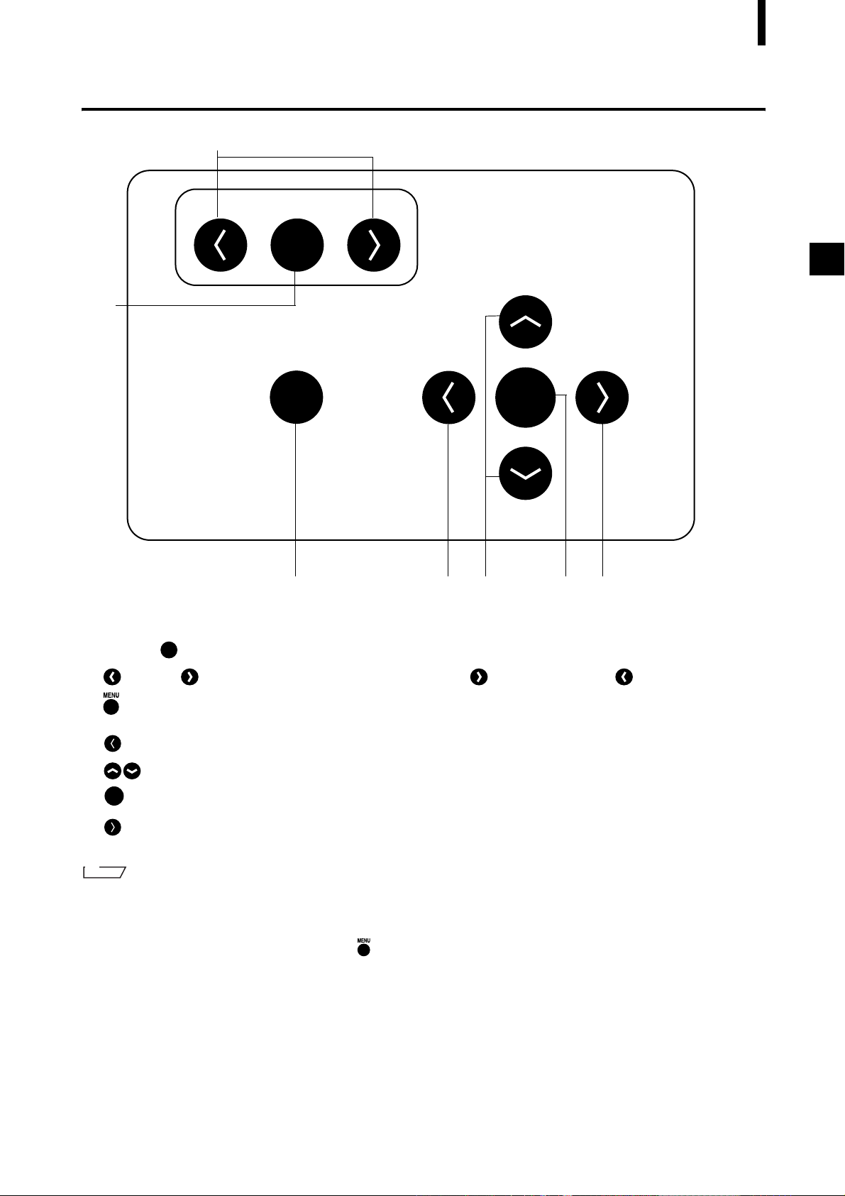
Operation Panel
2
1
Names and Functions of Parts
FOCUS
AUTO
MENU
CANCEL
SELECT
ENTER
3 4 5 6 7
1 FOCUS ..........................Focuses the image automatically.
AUTO
2 (Near) / (Far)...........Focuses the image manually. indicates “far” and indicates “near”.
3 .........................................Press once to display the menu on the viewfinder. Press again to close the
CANCEL
menu and return to the monitor image.
4 ........................................Cancels the current operation and returns to the preceding level.
5 ...................................Selects an item at the viewfinder.
ENTER
6 ........................................Sets the current selection, and moves to the next level (if any).
SELECT
7 ........................................Moves to the next level for the item currently selected in the viewfinder.
M
emo
If you wish to carry out a local operation while the unit is in REMOTE mode (while REMOTE is displayed in the viewfinder): Press any key to cancel REMOTE mode, and then press the appropriate keys for the operation you wish to carry
out.
(The MENU view may not be displayed even if is pressed depending on the view currently displayed.)
13
Page 16

Names and Functions of Parts
14
Page 17

Chapter 2
Preparation
15
Page 18

Connecting the AC Power Cord
To ensure correct connection of the AC power cord, read the points given in WARNING and CAUTION carefully.
WARNING
Always use the AC power cord supplied as a standard accessory with the VIVID 9i, and connect it to
an AC outlet (100-240 V , 50-60 Hz). Failure to do so may damage the VIVID 9i, causing a fire or
electric shock.
Do not bend, twist or pull the AC power cord excessively. Do not place heavy items on it, scratch or
modify it. Doing so may damage it, resulting in fire or electric shock.
If you are not going to use the VIVID 9i for a long time, disconnect the AC power cord from the AC
outlet. If dirt or water accumulates on the prongs of the AC power cord’s plug, it may cause a fire. If
there is any dirt or water on the prongs, it must be removed.
When disconnecting the AC power cord’s plug, always hold the plug and pull it to remove it. Never
pull the AC power cord itself as it may be damaged, resulting in fire or electric shock. Also do not insert
or disconnect the AC power cord’s plug with wet hands. Doing so may cause electric shock.
CAUTION
Plug the power cord into the outlet on the tripod or into a standard outlet. If using a standard outlet, be
sure that the ground terminal on the plug is correctly grounded. Improper connection may result in fire
or electric shock.
Make sure that the AC outlet is located near the VIVID 9i and the AC power cord’s plug can be easily
connected and disconnected.
[Connecting Procedure]
Set the power switch of the VIVID 9i to OFF
1
(“ ”).
Note
If the AC power cord is connected to an AC outlet with the
power switch set to ON (“ ”), damage to the VIVID 9i or
computer may result.
Before connecting the AC power cord, always make sure
that the power switch is set to OFF.
Plug the AC power cord to the AC power con-
2
nector on the VIVID 9i.
Plug the other end of the AC power cord to an
3
AC outlet.
POWER
SCSI
AC IN
16
Page 19

Connecting the VIVID 9i to a Computer
To operate the VIVID 9i from a computer using the Polygon Editing Tool, the VIVID 9i must be connected to
the computer with an standard SCSI cable VI-A20.
WARNING
The computer must be operated correctly and safely according to its instruction manual.
M
emo
• The standard SCSI cable has a 50-pin male plug (half-pitch, D-Sub) on both its ends.
• It is also possible to use a commercially available USB adapter. For details, please contact a KONICA MINOLTA
SENSING authorized service facility.
R
ef.
For a description of the standard accessories, refer to page 8.
[Connecting Procedure]
Set the power switch of both VIVID 9i and
1
computer to OFF (“ ”).
Note
If the AC power cord is connected to an AC outlet with the
power switch set to ON (“I”), damage to the VIVID 9i or
computer may result.
Always be sure that the digitizer and the computer are both
OFF before making connections.
POWER
SCSI
AC IN
Plug the SCSI cable to a SCSI port of the VIVID
2
9i.
Plug the other end of the SCSI cable to the
3
SCSI connector of the computer.
Connecting procedure is now complete
Note
Before turning ON the power to the computer, always turn
ON the power to the VIVID 9i and wait until it is ready for
operation (see page 21).
17
Page 20

Connecting the VIVID 9i to a Computer
Setting the SCSI ID No.
In order for the computer to recognize that the VIVID 9i is connected to the computer via the SCSI interface,
a SCSI ID No. (0 to 6) must be set for the VIVID 9i.
M
emo
SCSI ID No. 5 has been set as the default setting before shipment.
Note
If other devices are connected to the computer via the SCSI interface, make sure that the SCSI ID No. of the VIVID 9i
differs from those set for the devices.
[Setting Procedure]
Press .
1
The MENU view will appear.
Press to locate the arrow cursor to “SC-
2
SI SETTINGS”.
Press (or ).
3
SELECT
ENTER
The SCSI SETTINGS view will appear.
Press to locate the arrow cursor to “SC-
4
SI ID”.
Press (or ).
5
SELECT
ENTER
The currently selected SCSI ID No. will turn to pink.
STANDARD
COLOR OFF
W.B. DEFAULT
SCSI 5 ENABLED
WHITE BALANCE
INITIAL MODE
INITIAL CONDITION
→
SCSI SETTINGS
INFO
SCSI SETTINGS
→
SCSI ID 5
TERMINATE ENABLED
SCSI SETTINGS
SCSI ID 6
3 HQ ON NF ON
18
Press to select the desired SCSI ID No.
6
<Settings>
• 0 to 6: SCSI ID No.
7
Press .
ENTER
Setting is now complete.
Note
To cancel the setting and return the SCSI SETTINGS
screen to its original state, press .
CANCEL
TERMINATE ENABLED
Page 21

Connecting the VIVID 9i to a Computer
Setting the Terminator
The VIVID 9i has a built-in SCSI terminator. The terminator is required if the VIVID 9i is the last device of
those connected in series to the SCSI interface (i.e., if only one of the SCSI ports on the VIVID 9i is used).
If the terminator is not set correctly, the VIVID 9i or devices connected to the SCSI interface may malfunction.
M
emo
“ENABLED” has been selected as the default setting before shipment.
Note
“DISABLE” must be selected if the VIVID 9i is connected via the SCSI interface but is not the last device of those
connected in series, and “ENABLE” must be selected if it is not connected via the SCSI interface.
[Setting Procedure]
Press .
1
The MENU view will appear.
Press to locate the arrow cursor to “SC-
2
SI SETTINGS”.
Press (or ).
3
SELECT
ENTER
The SCSI SETTINGS view will appear.
Press to locate the arrow cursor to
4
“TERMINATE”.
Press (or ).
5
SELECT
ENTER
The currently selected option (ENABLED or DISABLED) will turn to pink.
STANDARD
COLOR OFF
W.B. DEFAULT
SCSI 5 ENABLED
WHITE BALANCE
INITIAL MODE
INITIAL CONDITION
→
SCSI SETTINGS
INFO
SCSI SETTINGS
SCSI ID 5
→
TERMINATE ENABLED
SCSI SETTINGS
SCSI ID 5
TERMINATE ENABLED
3 HQ ON NF ON
Press to select “ENABLED” or “DISA-
6
BLED”.
<Settings>
• ENABLED: Select this option if the terminator is to be
used.
• DISABLED: Select this option if the terminator is not to
be used.
19
Page 22

Connecting the VIVID 9i to a Computer
Press .
7
Setting is now complete.
Note
To cancel the setting and return the SCSI SETTINGS screen to its original state, press .
CANCEL
20
Page 23

Starting and Quitting
Starting the VIVID 9i
[Operating Procedure]
Set the power switch to ON (“ ”).
1
Power will be supplied to the VIVID 9i and initial setup is performed. After several dozen seconds,
“PLEASE OPEN LASER BARRIER AND PRESS
ANY KEY” will be displayed on the viewfinder.
Note
When turning power ON again after it has been turned
OFF, wait at least 5 seconds before doing so. Failure to observe this may result in malfunction or breakdown of the
VIVID 9i.
M
emo
To ensure precise measurement, allow the unit to warm up
for at least 10 minutes.
POWER
SCSI
AC IN
Remove the lens cap from the receiving lens.
2
Remove the laser barrier.
3
21
Page 24

Starting and Quitting
Press any key.
4
The MONITOR view will appear, indicating that the
VIVID 9i is now ready for operation.
EXTEND
720
MM
22
Page 25

Quitting the VIVID 9i
[Operating Procedure]
Set the power switch to OFF (“ ”).
1
Power will be turned OFF.
Attach the lens barrier.
2
POWER
Starting and Quitting
SCSI
AC IN
WARNING
To ensure safety, please keep the lens barrier in place at all times when the unit is not
in use.
Fit the lens cap onto the receiving lens.
3
Note
Please keep the receiving lens cap and the laser barrier
place in place when you are not carrying out scanning.
Dust and scratches on the laser and lens can adversely affect scanning precision.
23
Page 26

Mounting to the Tripod
When using the instrument with the tripod, first attach the tripod attachment to the instrument, and then attach
the instrument to the panhead/tripod.
CAUTION
• Make sure that the tripod attachment, panhead and tripod are secured to the instrument and each fas-
tener on the tripod is firmly tightened. Failure to observe this point may result in the tripod overturning
or the instrument dropping.
• When placing the tripod on a floor, examine the floor conditions and flatness to make sure that the tri-
pod is stably placed.
• After measurement is completed, the instrument must be removed from the tripod before storing them.
If the instrument is stored with the tripod attached, the tripod may overturn or the instrument may drop,
resulting in accidents.
1. Mounting the Tripod Attachment to the Instrument
Before mounting the instrument to the tripod, mount the tripod attachment to the instrument as explained below.
M
emo
Four screw holes for the tripod attachment are provided on base of the instrument.
[Operating Procedure]
After checking to ensure that you have turned off the power to the both the digitizer and
1
computer, disconnect the digitizer’s power cord and the SCSI cable.
Note
Note that disconnection of cables while power is ON may result in damage to the digitizer and/or the computer.
Be sure to turn off power at both sizes before disconnecting cables.
Slowly lean the digitizer over on a flat and sta-
2
ble surface, so that it is lying on the rubber
supports on its rear side.
Place the tripod attachment on the base of the
3
instrument, and secure it with the four screws
(supplied with the tripod attachment).
Tripod
Attachment
Note
Align the tripod attachment and digitizer so that the projecting area of the attachment fits into the receding area on
the base of the digitizer.
24
Page 27

Mounting to the Tripod
2. Mounting the Instrument to the Panhead
After you have attached the tripod attachment to the instrument, they need to be mounted to the recommended
panhead as explained below.
First, remove the accessory plate from the panhead, attach it to the instrument, then attach both to the panhead.
M
emo
Three screw holes are provided on the back of the tripod attachment, to allow mounting the tripod attachment to the panhead.
[Operating Procedure]
Remove the accessory plate from the panhead.
1
Place the top of the accessory plate on the tri-
2
pod attachment (attached to the instrument),
and secure them with two screws (U3/8, supplied with the accessory plate).
Accessory Plate
U3/8 Screw
Make sure that the tripod/panhead is secured in place.
3
Slide the accessory plate (attached to the tripod attachment on the instrument) into the
4
panhead.
M
emo
Slide and attach the plate from front of the panhead.
Tighten the slide fixing knob to firmly secure the accessory plate to the panhead.
5
M
emo
Refer to the tripod/panhead instruction manual for details on using the accessory plate locking knob.
25
Page 28

Mounting to the Tripod
26
Page 29

Chapter 3
Operation
27
Page 30

Replacing the Lens and Field Calibration
With the VIVID 9i, three types of lens are available: WIDE lens, MIDDLE lens and TELE lens. Be sure to
mount the lens that best matches the subject’s size and distance. Before taking scans of a subject, most suitable
lens for the size of the object and distance must be used.
Note
After changing the lens, you need to recalibrate using the field calibration system. For Field Calibration, refer to page
32.
Relationship between Measurement Distance and Object
Select the most suitable lens by referring to the table given below.
M
emo
The closer the object to the VIVID 9i, the higher the measurement accuracy is. On the other hand, influences of shades
produced due to roughness on the surface of the object can be reduced if the object is positioned far from the VIVID 9i.
WIDE Lens
Measurement Distance 500 600 800 1000 2500
Object Size
Horizontal 299 359 478 598 1495
Vertical 224 269 359 449 1121
Unit (mm)
MIDDLE Lens
TELE Lens
Measurement Distance 500 600 800 1000 2500
Object Size
Measurement Distance 500 600 800 1000 2500
Object Size
Horizontal 165 198 263 329 823
Vertical 124 148 198 247 618
Unit (mm)
Horizontal 93 111 148 185 463
Vertical 69 83 111 139 347
Unit (mm)
28
Page 31

Replacing the Lens and Field Calibration
Replacing Procedure
You can use the status information to see what type of lens is currently attached. The lens type is also written
on the lens itself.
The explanation below assume that the power to the digitizer is ON, but note that it is also possible to change
the lens while the power is OFF. If the power is OFF, however, you cannot use the digitizer’s viewfinder or
control keys.
R
ef.
For display of the status information, refer to page 44.
Note
• Only the lenses supplied as standard accessories with the VIVID 9i can be used. (They are not compatible with other
VIVID models since they have been calibrated with the VIVID 9i only.)
• Since the VIVID 9i is a precision instrument, do not leave it without lens when replacing the lens. Replace the lens
as soon as possible.
• Do not touch the lens surface with fingers.
• Dust and scratches on the lens surface may adversely affect precision. When not using the digitizer, keep the lens
cap on the lens. If the lens is dusty, clean it with a camera blower.
• Dust or dirt on the lens mount surface may produce incorrect measurement data. In this case, wipe the lens mount
surface with a clean, dry cloth and then blow it with a camera air blower etc.
• Dust and dirt collected on the lens mount surface on the body side must also be removed with a camera air blower etc.
• SCSI communication is not available while the lens is being replaced. Please close the Polygon Editing Tool software’s control dialog before starting replacement.
[Operating Procedure]
Remove the lens hood.
1
Turn counterclockwise to align with the cutouts.
M
emo
The lens hood can be fixed with its bayonet mount.
Turn the lens fixing ring counter-clockwise to
2
loose it completely.
M
emo
The lens fixing ring can be fixed with its screw mount.
29
Page 32

Replacing the Lens and Field Calibration
Hold the external edge of the fixing ring and
3
pull it out.
M
emo
Hold the ring with your finger located near the red mark on
the lens. This will facilitate pulling the lens.
Note
Attach the lens cap to the removed lens, place it in the lens
case and keep it in a safe place.
The following information will appear in the viewfinder as shown on the right.
CHANGE LENS
S/N 2001005
PRESS ANY KEY
AND SCAN FIELD
CALIBRATION SYSTEM
Attach the desired lens.
4
• Remove the lens cap.
• Align the red mark on the lens with the one on the
lens mount socket, and insert the lens until a click is
heard.
M
emo
Hold the ring with your finger located near the red mark on
the lens. This will facilitate inserting the lens.
Turn the lens fixing ring clockwise to secure
5
the lens.
Note
After tightening the lens, make sure that the red mark on
the ring is aligned with the red mark on the body.
Tightening ring
Red
mark
30
Red mark
Page 33

Replacing the Lens and Field Calibration
Attach the lens hood.
6
Align the cutouts, and then turn clockwise.
M
emo
The hood must be turned until it contacts the bayonet mount
socket.
Press any key.
7
After several dozen seconds, “PLEASE OPEN LASER BARRIER AND PRESS ANY KEY” will be
displayed on the viewfinder.
Press any key.
8
The viewfinder displays the monitor screen, and the digitizer is ready for use.
Note
Place a lens cap on the lens you removed, put it in its case, and store in a safe place.
Use the field calibration system and the Polygon Editing Tool software to calibrate the
9
system.
R
ef.
For the field calibration procedure, refer to “Field Calibration” on the next page.
31
Page 34

Field Calibration
The field calibration on this unit is done using the Field Calibration System.
Periodic field calibration is recommended to maintain measurement precision.
Note
• Always carry out field calibration when changing lenses.
• The Field Calibration System that corresponds to the type of lens the unit is equipped with must be used when conducting field calibration.
• This unit and the Field Calibration System are paired, so it is not possible to correctly calibrate it when the serial
numbers differ. Use the unit and Field Calibration System combination that have the same serial number.
M
emo
The type of lens the unit is equipped with and the serial number of the unit can be confirmed in the Status information.
R
ef.
For details on displaying the status information, refer to page 41.
Field Calibration System
The Field Calibration System is comprised of the Unit Section which contains the Field Calibration System,
which corresponds to the type of lens on the unit, and the Frame Section, which maintains a facing position at
a set distance from the unit.
• Parts Nomenclature
Lock Lever B
Lock Lever A
Handle B
Support
Section
Rubber Foot (×6): With Height Adjustment Mechanism
The rubber feet adjustment mechanism has a structure
*
shown in the drawing below.
Handle A
Unit Section (Field Calibration System)
Equipped with field calibration systems for the
*
WIDE lens type and MIDDLE/TELE lens type.
Unit Section Cover
Unit Attachment Section
Frame Section
(Frame for Calibration System)
(Frame section)
Stopper
Lock nut
Main Unit Attachment
Section
32
Rubber foot block
[Specifications]
• Lowest height: 43mm
• Adjustable range: Max. 10mm (with no preventive structure)
Page 35

Field Calibration
• Installation Space
A secure installation location that meets the dimensional requirements as shown in the drawing below is necessary to install the Field Calibration System. Before using the Field Calibration System, a “Calibration Area”
for stable and high quality calibration is required, in addition to the place that is necessary to position the Field
Calibration System.
Approx. 73 cm
Approx. 145 cm
Installation Space
Approx. 46 cm
• Calibration Area
The “Calibration Area” is the box shaped area shown in the drawing below.
The dimensions are:
• 30 cm or less in front of or behind the Chart unit
• 20 cm or less right or left to the Chart unit
• 20 cm or less above the Chart unit
Note
• Prevent foreign matter from getting into the “Calibration Area”. When executing Field Calibration, do not allow
workers into the area. It may result in incorrect calibration.
• Be careful to block incident light from the outside. Execute Field Calibration under fluorescent light at less than
500lx.
• Prevent light from windows.
In 20 cm above the Chart unit
In 30 cm front of
or behind the Chart unit
In 20 cm right or left to
the Chart unit
Calibration Area
33
Page 36

Field Calibration
Executing Field Calibration
The Field Calibration System is made up of the Field Calibration System Section and the Frame Section. It is
necessary to assemble it when it is to be used for the first time or after it has been temporarily disassembled to
move the Field Calibration System, etc. In addition, it is necessary to attach the Field Calibration System to the
main unit in order to carry out field calibration.
M
emo
VIVID 9i/VI-9i has been calibrated at 20ºC. The allowable operating environment is 10ºC to 40ºC, but we recommend
that you execute Field Calibration or scan the objects in environments where ambient temperature is 20ºC (68ºF).
Assembling the Field Calibration System
[Procedure]
Install the Frame Section.
1
Install the Frame Section in a secure location with sufficient space.
Note
For the place that is necessary to install the Frame of the
Field Calibration System, see page 33 of this instruction
manual. A “Calibration Area” is also required for executing the calibration.
Adjust the Height of Rubber Feet to Stabilize the Frame Section.
2
The Frame of the Field Calibration System is designed to be used on a sufficiently wide, stable, flat surface. However, even if a sufficiently wide space is available, the surface may not be completely flat, resulting in one or more of the rubber feet of the frame not being in contact with the surface. To solve this
problem, the feet have been equipped evenly with a mechanism to allow their height to be adjusted.
M
emo
All 6 rubber feet have height adjustment mechanisms.
Note
• Adjust a height of the rubber feet without any item on the frame during the procedure for setting up the frame
of this system.
• When transporting this system, set the rubber feet to their lowest height to avoid damage to the shopping box.
1Turn the lock nut counterclockwise to unlock the
rubber foot block.
34
Unlock the rubber
foot block by turning the lock nut
counterclockwise.
Page 37

2Turn the lock nut counterclockwise to unlock the
rubber foot block.
M
emo
Turn clockwise for lower heights and counterclockwise for
higher heights.
Note
Because there is no preventive structure, moving the rubber foot block more than adjustable range may cause the
rubber foot block to fall off. In this case, screw the rubber
foot block onto the stopper unit clockwise.
3After adjusting the height correctly, move the lock
nut to the stopper unit by turning it clockwise and
lock the rubber foot block.
Field Calibration
Adjust the height
by turning the Rubber foot block.
• The lock nut
moves in the
same height direction as the
rubber foot block.
After adjustment of
the height, move
the lock nut to the
stopper unit by
turning it clockwise
and lock the rubber foot block in
place.
Attach the Unit Attachment Section to the
3
Field Calibration System Unit Section.
Use the 4 screws and tighten them firmly with the included hex wrench.
Attach the VIVID 9i Attachment Section to the
4
main unit.
Make sure the footings at the base of the main unit are
inserted into the 4 footing seats.
35
Page 38

Field Calibration
Field Calibration System Preparation
There are two types of field calibration systems: one for WIDE lens type use and the other for MIDDLE/TELE
lens type use. Use the Field Calibration System that corresponds to the type of lens the main unit is equipped
with.
[Procedure]
• Preparing the Wide Lens Field Calibration System
Open the cover of the Field Calibration Sys-
1
tem Unit Section.
1Pull Lock Lever A down to the UNLOCK posi-
tion.
2Grasp Handle A and Handle B with both hands
and pull to spread open.
Note
There may be instances where the Field Calibration System for the WIDE lens will slightly jut out when the Unit
Section Cover is opened.
When using the Field Calibration System for the WIDE
lens, gently push on it to return the Field Calibration System to the unit side.
Pull Lock Lever A down to
the UNLOCK position.
Grasp firmly with
both hands and pull
to open.
• Preparing the MIDDLE/TELE Lens Field Calibration System
Open the Field Calibration System Unit for the
1
WIDE lens.
1Pull Lock Lever B down to the UNLOCK posi-
tion.
2Grasp Handle B and the Support Section of the
Field Calibration System Section using both
hands and pull to spread open.
M
emo
The Field Calibration System for the MIDDLE/TELE lens
may be opened using the procedure for opening the Field
Calibration System unit for the WIDE lens or it may be
opened by opening the Unit Section Cover and then opening
the Field Calibration System for the WIDE lens.
1
* There may be cases in which
the Field Calibration System
for the WIDE lens type will jut
out slightly when the Unit
Section Cover is opened, so
gently push on it to return it
to its position.
Pull Lock Lever B down
to the UNLOCK position.
2
Grasp firmly with
both hands and pull
to open.
36
1
2
Page 39

Field Calibration
Executing Field Calibration
Field Calibration on this unit is carried out using the Polygon Editing Tool Software. After the assembly of the
Field Calibration System has been completed and the unit connected to a PC and powered on, it will be necessary to start up the Polygon Editing Tool software.
Note
• Prevent foreign matter from getting into the “Calibration Area”. When executing Field Calibration, do not allow
workers into the area. It may result in incorrect calibration.
• Be careful to block incident light from the outside. Execute Field Calibration under fluorescent light at less than
500lx.
• Prevent light from windows.
R
ef.
For details, refer to page 13, in the Polygon Editing Tool Instruction Manual.
[Procedure]
At the [File] menu, click [Select Digitizer].
1
Select [VIVID9i (VI-9i)], and click [OK].
2
Note
If you change the selection from one digitizer to another at
this dialog, the newly selected digitizer cannot be used until
you start the software again.
At the [File] menu, click [Exit] to close the software. Then start the software again.
3
Note
You can skip this step if “none” was originally selected when you opened the Select Digitizer dialog at Step 2
above.
37
Page 40

Field Calibration
At the [File] menu, select [Import-Digitizer], and click [One Scan] or [Step Scan].
4
The software opens the [File-Import-Digitizer-One Scan] or [File-Import-Digitizer-Step Scan] dialog.
The dialog’s work window shows a field calibration image.
M
emo
There is a possibility that the image of the Field Calibration Chart is displayed out of center in the Work window
of the dialog box or the finder of the instrument due to individual differences of the VIVID 9i/VI-9i or Field Calibration System. It does not have an effect on the result of Field Calibration.
Note
If the image of the Calibration Chart isn’t displayed in the angle of the VIVID 9i/VI-9i’s finder or Work window
of the dialog box of the Polygon Editing Tool, setting of Field Calibration Chart or the instrument might be incorrect. Reinstall them correctly again.
(The following example is from the [File-Import-Digitizer-One Scan] dialog.)
[OK]
button
Work window
Click the [Calibration] button.
5
The system carries out field calibration.
[Calibration] button
38
Page 41

Field Calibration
Check that field calibration was successful.
6
If you are using field calibration results to measure the dimensions of the field calibration system, the
software shows the differences from the measurements made at time of shipping. Differences are shown
for four places: X1, Y1, X2, and Y2.
• If field calibration was not successful, one of the following messages appears. Proceed in accordance
with the displayed message.
Message Meaning What To Do
Field Calibration:
Scan Error
Field Calibration:
Evaluate Error
Field Calibration:
Calibrate Error
Failed to recognize
the field calibration
system.
Failed to correctly
measure the field
calibration system.
Adequate field calibration results cannot be obtained.
• Remove the laser barrier and the receiving lens cap.
• Check that you are using the correct system type for the lens
used.
• Check that foreign matter is not in the “Calibration Area”.
• Check that there is no effect of light from outside.
• Be sure that the Field Calibration Chart unit is correctly
mounted to the Frame section.
• Check that the image of the Field Calibration Chart is correctly displayed in the view angle of the finger of the VIVID
9i/VI-9i or the Work window of the dialog box of the Polygon Editing Tool.
• Remove the lens, and then set it again correctly.
• Check that foreign matter is not in the “Calibration Area”.
• Check that there is no effect of light from outside.
• Be sure that the Field Calibration Chart unit is correctly
mounted to the Frame section.
• Check that the image of the Field Calibration Chart is correctly displayed in the view angle of the finger of the VIVID
9i/VI-9i or the Work window of the dialog box of the Polygon Editing Tool.
• When multiple units of the instrument are used, check to
make sure that the Field Calibration System matches the
serial number of the instrument.
• If there is any dirt on the laser window or the receiving lens,
clean these as explained on page 3.
• Clean off any dust on the field calibration system.
• If the field calibration system is scratched or dented, contact
a KONICA MINOLTA SENSING authorized service facility.
• If the same error recurs when you retry the field calibration,
contact a KONICA MINOLTA SENSING authorized service facility.
Click the [Cancel] button.
7
The dialog closes, and field calibration is completed.
39
Page 42

Field Calibration
Ending Field Calibration
After the field calibration is finished, remove the unit from the Field Calibration System. Also close the Field
Calibration System that was used and return it to its original condition.
[Procedure]
Remove the unit from the Attachment Section
1
of the main unit.
Close the Field Calibration System.
2
Note
• Be careful not to pinch your fingers in the opening and
closing section when you shut the Field Calibration System.
• The Field Calibration System may be degraded if left
open. Always close and store the Field Calibration System after use.
• In the case where the MIDDLE/TELE lens type Field
Calibration System has been opened after opening the
WIDE lens type Field Calibration System, the Field Calibration System for the WIDE lens type and the Unit Section Cover will be separated so be sure to close the Unit
Section Cover only after closing the WIDE lens type
Field Calibration System.
1Close the Field Calibration System
for the MIDDLE/TELE lens type.
2Close the Field Calibration System
for the WIDE lens type.
* In the case where the MIDDLE/TELE lens type
Field Calibration System has been opened after
opening the WIDE lens type Field Calibration System, first close the WIDE lens type Field Calibration System and then close the unit section cover.
40
The Field Calibration System can be stored as is, without disassembling it into the Field Calibration System
Unit Section and the Frame Section.
In the case where the system has to be disassembled and stored for reasons related to installation space requirements or to move or transport it, follow the procedure outlined below to disassemble it.
Page 43

Field Calibration
Disassembling the Field Calibration System
In cases where the Field Calibration System needs to be disassembled to move or transport it or for reasons
related to its installation space, separate the Field Calibration System into the Field Calibration System Unit
and the Frame sections.
Note
Do not disassemble any sections that are not covered in this document. Doing so may lead to a reduction in precision.
[Procedure]
Remove the Unit Attachment Section from the
1
Field Calibration System Unit Section.
Use the included hex wrench to remove the 4 screws.
M
emo
Carefully store the screws that are removed with the Field
Calibration System Unit Section.
Store the Field Calibration System Unit Section and the Frame Section in an appropriate
2
place.
Note
• Do not store the Frame Section in an upright position.
• Store the Field Calibration System Section in a closed condition.
• Even when 2 or more persons are available to move or transport the Field Calibration System, always disassemble it
before attempting to move it.
41
Page 44

Adjusting the White Balance
The color of an object varies slightly depending on the type of light source. To acquire accurate color image
data, adjust the white balance as described below under the light source to be used.
When scanning, we recommend that you use a stable, flicker-free light source (such as a high-frequency fluorescent lamp).
M
emo
The white balance has been adjusted under fluorescent light before shipment.
[Operating Procedure]
Set the light source so that the lighting condition is the same as that under which scan
1
is to be performed.
Attach the white balance cap to the VIVID 9i as
2
illustrated.
Press .
3
The MENU view will appear.
Press to locate the arrow cursor to
4
“WHITE BALANCE”.
STANDARD 3 HQ ON NF ON
COLOR OFF
W.B. DEFAULT
SCSI 5 ENABLED
→
WHITE BALANCE
INITIAL MODE
INITIAL CONDITION
SCSI SETTINGS
INFO
42
Page 45

Adjusting the White Balance
SELECT
Press (or ).
5
The WHITE BALANCE view will appear.
Press as necessary to select one of the
6
following settings.
<Setting>
• DEFAULT: Adjusts for fluorescent light.
• USER’S: Uses the previously adjusted white balance.
• CALIBRATION: Adjusts white balance automatically.
Press .
7
If [CALIBRATION] was selected, the digitizer displays the screen shown at right and automatically adjusts the white balance. When adjustment is complete,
the display returns to the Menu screen. The adjusted
white balance is saved into USER’S.
If DEFAULT or USER’S was selected, adjustment is
completed and the display returns to the Menu page.
ENTER
ENTER
WHITE BALANCE DEFAULT
CALIBRATING
43
Page 46

Displaying the Status Information
The model name, version, lens, field calibration system information can be displayed.
[Operating Procedure]
Press .
1
The MENU view will appear.
Press to locate the arrow cursor to “IN-
2
FO”.
Press (or ).
3
SELECT
ENTER
The status information will be displayed as shown below.
Item Explanation
Displays information
CAMERA
MODEL
NAME
VERSION
LENS
S/N Shows the serial number.
FIELD CALIBRATION
SYSTEM
S/N
about the VIVID 9i digitizer.
Shows the model name
(“VIVID 9i”).
Displays the internal software’s version number.
Identifies the lens that is
currently mounted.
TELE: Telephoto lens
MIDDLE: Middle lens
WIDE: Wide lens
Shows information about
the field calibration system.
Shows the serial number of
the field calibration system.
STANDARD 3 HQ ON NF ON
COLOR OFF
W.B. DEFAULT
SCSI 5 ENABLED
WHITE BALANCE
INITIAL MODE
INITIAL CONDITION
SCSI SETTINGS
→
INFO
INFO
CAMERA
MODEL NAME 9I
VERSION 1.00
LENS MIDDLE
S/N 2001005
FIELD CALIBRATION SYSTEM
S/N 2001005
44
Page 47

Adjusting the Laser Power and CCD Gain
Manually
With certain objects, correct image data cannot be obtained.
In this case, adjust the laser power and CCD gain as explained below.
Adjustment must be made using the Polygon Editing Tool software. For information about how to proceed,
refer to the software’s operation manual.
M
emo
With the following objects, correct data may not be acquired, the laser power or CCD gain must be adjusted manually.
• Glass etc. which transmit light
• Mirrors etc. which cause mirror reflection
• Electric bulbs etc. which themselves illuminate
• Black or blue cloth which has a low reflectance for red and similar colors
45
Page 48

Setting the Scan Mode
The setting of scan mode can be set with Polygon Editing Tool software, and the setting is the top priority. It
is not required to set by VIVID 9i.
If you are not making scan settings from your PC’s software (for example, if using a customized program),
please make the settings at the digitizer itself.
Only settings are explained here.
Note
These settings become effective from the time of next start.
STANDARD 3 HQ ON NF ON
COLOR OFF
W.B. DEFAULT
SCSI 5 ENABLED
WHITE BALANCE
→
INITIAL MODE
INITIAL CONDITION
SCSI SETTINGS
INFO
Item Explanation
INITIAL MODE Selects one of the preset scan modes.
Selects the scan mode.
• STANDARD: Allowable distance is 600 to 1000 mm.
The following initial conditions cannot be changed:
NOISE FILTER: ON; HIGH QUALITY: ON
DIGITIZE
COLOR
INITIAL CONDITION
NUMBER OF
SCANS
NOISE FILTER If ON, noise filtering is applied to scan data.
HIGH QUALITY If ON, unreliable scan data is discarded.
DARK
LOG
• EXTENDED: Allowable distance is 500 to 2500 mm.
The following initial conditions cannot be changed:
NOISE FILTER: ON; HIGH QUALITY: OFF
• USER: Allowable distance is 500 to 2500 mm.
Initial conditions can be changed as desired.
Selects the color mode for image capture.
• ON: Full color
• OFF: No image
Makes settings that are more detailed than the initial mode settings. Available settings vary according to the selected initial mode.
Initial conditions that cannot be changed (as determined by the DIGITIZE scan
mode) are not displayed.
Sets number of scans. Allows for increased dynamic range.
If ON, dark correction is applied to color data. Use this feature when you want to
remove the CCD offset components and get the signal components only. This setting is not shown if INITIAL MODE-COLOR is set to OFF.>
If ON, log correction is applied to color data. Use this feature when you want to
brighten intermediate colors. This setting is not shown if INITIAL MODE-COLOR
is set to OFF.
46
Page 49

Chapter 4
Appendix
47
Page 50

Error Messages
The following error messages appear if incorrect operation is performed or an abnormality occurs with the
VIVID 9i. If an error message appears, take the appropriate corrective actions as shown in the table below. If
the problem still does not disappear, contact a KONICA MINOLTA SENSING authorized service facility.
Error Message
(Alphabetically)
AF ERROR
LOW CONTRAST
PRESS ANY KEY
BACKUP ERROR
PRESS ANY KEY
BACKUP ERROR
PRESS ANY KEY AND SCAN
FIELD CALIBRATION SYSTEM
CAUTION
LASER SCANNER IS
OUT OF ORDER
PLEASE TURN OFF
CHANGE LENS
S/N ********
PRESS ANY KEY AND SCAN
FIELD CALIBRATION SYSTEM
LIGHT IMPROPER Inadequacy amount of light Illuminate the object brighter and scan it.
SAME FILE NAME A file of the same file name already
SYSTEM ERROR
PLEASE TURN OFF
TERMINATE ERROR
PRESS ANY KEY
SET TERMINATE ENABLE
WB ERROR
LIGHT IMPROPER
PRESS ANY KEY
Auto-focus failed due to low contrast
of the object. Press any key.
Failed to back up the data.
Press any key.
Failed to back up field calibration
values.
Press any key and scan field calibration system.
The laser beam is not emitted properly. Turn off the power immediately.
The lens is now being replaced.
Press any key and scan field calibration system.
exists.
A system error has occurred.
Turn OFF the power.
SCSI terminator error has occurred.
Press any key and set the terminator
to “ENABLE”.
Failed to adjust white balance.
Press any key.
Meaning Action
Set the manual focus.
All the settings will be initialized, so set
them again.
Field calibration values have been reinitialized. Please try field calibration again.
Highly dangerous! Turn off the power
immediately and contact a KONICA
MINOLTA SENSING authorized service
facility.
Attach the lens hood properly.
Check the serial No. of the lens, and
replace the lens properly.
Specify another file name.
Turn OFF the power, then turn it ON
again. If the problem still does not disappear, contact a KONICA MINOLTA
SENSING-authorized service facility.
Set the terminator to “ENABLE”.
Adjust white balance in a bright place.
(White balance in effect before occurrence of this error has not been updated.)
48
Page 51

Explanation of Measuring Principle
Measuring Principle
The VIVID 9i uses the light-stripe method to emit a horizontal stripe light through a cylindrical lens to the object. The reflected light from the object is received by the CCD, and then converted by triangulation into distance information.
This process is repeated by scanning the stripe light vertically on the object surface using a Galvano mirror, to
obtain a 3D image data of the object.
In addition, a color image of the object is also obtained by scanning the CCD through a RGB filter while the
stripe light is not emitted. (A band pass filter is used when stripe light is emitted.)
CCD
Laser beam
Emitting lens
Galvano mirror
Filter set (R, G, B, BP)/rotary type
Receiving lens (Exchange type)
Object
49
Page 52

Explanation of Measuring Principle
High-Speed Image Processing Circuit
The stripe light is scanned on the CCD image plane at one horizontal line per frame, and the CCD is driven so
that the block readout start position is shifted one line per frame.
Approximately 600 frames are acquired.
· CCD drive rate: 12.5MHz
· Block readout: 125 lines
· Data acquisition speed: 2.5 sec.
The output signal from the CCD is then converted into a digital signal, which is then subjected to digital signal
processing. The signal processed data is finally saved in the frame memory.
Frame
Memory
Frame interline
Transfer CCD
A/D
FIFO
DSP
Galvano
Scanner
Clock Generator
Laser
Diode
Driver
CPU
CPU Data Bus
Host I/F
Time center of gravity and Space center of gravity
Time center of gravity is the center of gravity of the variation in the LD light passing CCD’s one picture element over a period of time.
Space center of gravity is the center of gravity of the spatial variation in the LD light on the CCD at a certain
time.
With this instrument, 3D images are obtained by calculating the Time center of gravity of each picture element
of CCD. Intersection of the viewing angle of each picture element of the CCD and passing angle (time) of the
stripe light is calculated.
Compared to the Space center of gravity, use of Time center of gravity can reduce influences of sensitivity variation of CCD’s picture elements and variation of brightness of the object.
50
Page 53

Dimension Diagram
18
474.5
412.5
(Unit: mm)
282.6
289.8
300.3
221
51
Page 54

Specifications
Model Name Non-contact 3D digitizer VIVID 9i/VI-9i
Measurement Method Triangulation, light block method
AF Image surface AF (contrast method), Active AF
Light-Receiving lens (Interchangeable)
Object Distance Range 0.6 to 2.5 m
Scan Range 0.6 to 1.0 m (In Standard mode), 0.5 to 2.5 m (In Extended mode)
Laser Scan Method Galvano mirror
Laser Class Class 2 (IEC60825-1), Class 1 (FDA), Max. 30 mW, 690 nm
X Direction Input Range
(In Extended mode)
Y Direction Input Range
(In Extended mode)
Z Direction Input Range
(In Extended mode)
Accuracy TELE XYZ: ±0.05 mm/ ±0.10 mm
Precision (Z, σ) TELE 0.008 mm/ ±0.024 mm
Input Time (per scan) 2.5 sec.
Transfer Time to Host Computer
Ambient Lighting Condition Office environment, 500 lx or less
Imaging Element 3D data : 1/3-inch frame transfer CCD (340,000 pixels)
Number of Output Pixels 3D data : 640
Output Format 3D data: Konica Minolta format, & (STL, DXF, OBJ, ASCII points, VRML)
Data File Size Total 3D and color data capacity: 3.6 MB per data
Viewfinder 5.7-inch LCD (320 × 240 picture elements)
Output Interface SCSI II (DMA synchronous transfer)
Power Commercial AC power, 100-240 V (50-60Hz), rated current 0.6 A (at 100 V AC)
Dimensions 221 (W) × 412 (H) × 282 (D) mm
Mass Approx. 15 kg (with lens attached)
Temperature / Humidity Operating environment: 10 to 40°C (50°F to 104°F); 65% RH or less/no condensa-
Storage Temperature Range 0 to 40°C, 85% or less (at 35°C)/no condensation
TELE : Focal distance f=25 mm
MIDDLE: Focal distance f=14 mm
WIDE : Focal distance f=8 mm
93 to 463 mm (TELE), 165 to 823 mm (MIDDLE),
299 to 1495 mm (WIDE)
69 to 347 mm (TELE), 124 to 618 mm (MIDDLE),
224 to 1121 mm (WIDE)
26 to 680 mm (TELE), 42 to 1100 mm (MIDDLE),
66 to 1750 mm (WIDE mode)
MIDDLE XYZ: ±0.10 mm/ ±0.20 mm
WIDE XYZ: ±0.20 mm/ ±0.40 mm
(Conditions: Distance 0.6 m/ 1.0 m, KONICA MINOLTA SENSING’s standard 3D
chart, KONICA MINOLTA SENSING’s processing software, temperature 20ºC, relative humidity 65% or less)
MIDDLE 0.016 mm/ ±0.048 mm
WIDE 0.032 mm/ ±0.096 mm
(Conditions: Distance 0.6 m/ 1.0 m, KONICA MINOLTA SENSING’s standard 2D
chart, KONICA MINOLTA SENSING’s processing software, temperature 20°C, relative humidity 65% or less)
Approx. 1.5 sec.
Color data : Common with 3D data (color separation by rotary filter)
x
× 480 (640
Color data : 640 × 480
(Converted to 3D data by the Polygon Editing Tool Software / standard accessory)
Color data : RGB 24-bit raster scan data
* There may be rare cases in which the point that is normally lit or unlit may break up
(dot break up); however, this will not have any influence on the scanning data.
tion; Installation category: II; Pollution degree: 2; Maximum altitude: 2000 m
460 in the HIGH QUALITY mode)
52
The above specifications are subject to change without prior notice.
Page 55

Page 56

9222-1750-11
© 2004 KONICA MINOLTA SENSING, INC. AFHCKR(4) Printed in Japan
 Loading...