

Page 1

NON-CONTACT 3D DIGITIZER
VIVID 300/VI-300
INSTRUCTION MANUAL (HARDW ARE)
Page 2

Safety Symbols
The following symbols are used in this manual to prevent accidents which may occur as result of
incorrect use of the instrument.
Denotes a sentence regarding safety warning or note.
Read the sentence carefully to ensure safe and correct use.
Denotes a prohibited operation.
The operation must never been performed.
Denotes an instruction.
The instruction must be strictly adhered to.
Denotes an instruction.
Disconnect the AC power cord from the AC outlet.
Denotes a prohibited operation.
The part must never be disassembled.
Denotes a sentence regarding safety precaution for laser .
Read the sentence carefully to ensure safe and correct use.
Denotes an instruction.
Connect the grounding terminal as instructed.
Page 3

SAFETY PRECAUTIONS
• To ensure correct use of the VIVID 300, read the following points carefully and adhere to them. After you have
read this manual, keep it in a safe place where it can be referred to anytime a question arises.
WARNING (Failure to adhere to the following points may result in death or serious injury.)
Do not use the VIVID 300 in places where flammable or combustible gases (gasoline etc.) are present.
Doing so may cause a fire.
Always use the AC power cord supplied as a standard accessory with the VIVID 300, and connect it to
an AC outlet (100-240 Vac, 50-60 Hz). Failure to
do so may damage the VIVID 300, causing a fire or
electric shock.
Do not bend, twist or pull the AC power cord excessively. In addition, do not place heavy items on the
AC power cord, or damage or modify it in any way.
Doing so may cause damage to the AC power cord,
resulting in fire or electric shock.
If the VIVID 300 will not be used for a long time,
disconnect the AC power cord from the AC outlet.
Accumulated dirt or water on the prongs of the AC
power cord’s plug may cause a fire. If there is any
dirt or water on the prongs of the AC power cord’s
plug, remove it.
When disconnecting the AC power cord’s plug, always hold the plug and pull it to remove it. Never
pull the AC power cord itself. Doing so may damage the AC power cord, causing a fire or electric
shock. In addition, do not insert or disconnect the
AC power cord’s plug with wet hands. Doing so
may cause electric shock.
The VIVID 300 should not be operated if it is damaged, or smoke or odd smells are detected. Doing
so may result in a fire. In such situations, turn the
power OFF immediately , disconnect the AC power
cord from the AC outlet, and contact the nearest
Minolta-authorized service facility.
Do not disassemble or modify the VIVID 300. Doing
so may cause a fire or electric shock.
T ake special care not to allow liquid or metal objects
to enter the VIVID 300. Doing so may cause a fire or
electric shock. Should liquid or metal objects enter
the VIVID 300, turn the power OFF immediately , disconnect the AC power cord from the AC outlet, and
contact the nearest Minolta-authorized service facility .
The VIVID 300 should not be operated if dirt or dust
has entered through the vent holes. Doing so may
result in a fire. For periodic inspection, contact the
nearest Minolta-authorized service facility.
Never stare into the laser emitting window.
Do not place a lens, mirror or optical element in the
passage of the laser beam. Doing so may converge
the laser beam, resulting in damage to your eyes,
burns or fire. To prevent the above accidents, make
sure that a wall or similar which can block the laser
beam is located behind the object.
CAUTION
For Continued protection against risk of fire or electrical shock a mains plug shall connect to grounding-type socket outlet.
Before connecting the grounding terminal, make
sure that the AC power cord is not connected to the
AC outlet. Failure to do observe this may cause
electric shock.
Do not place the VIVID 300 on an unstable or sloping surface. Doing so may result in its dropping or
overturning, causing injury. Take care not to drop
the VIVID 300 when carrying it.
(Falling to adhere to the following points may result in injury or damage to the VIVID
300 or other property.)
When replacing the fuse, first turn the power OFF,
disconnect the AC power cord from the AC outlet,
then replace it with one which conforms to the required specifications. If the fuse blows off soon after
it has been replaced, contact the nearest Minoltaauthorized service facility.
The socket-outlet shall be installed near the machine
and shall be easily accessible.
1
Page 4

FOREWORD
The VIVID 300 (for non-Europe)/VI-300 (for Europe) is designed for non-contact acquisition of 3D image data of an
object by emitting a laser beam to the object and acquiring its shading images.
Please note that the VIVID 300 model name is intended only for reference with this manual.
NOTES ON USE
This instrument should be used under the following environmental conditions:
• Indoor use only
• Maximum altitude: 2000 m
• Ambient temperature: 10 to 35°C
• Humidity: Less than relative humidity of 85% (at 35°C) with no condensation
• Allowable fluctuation of power supply voltage: ±10% of nominal voltage
• Installation category 2
• Pollution degree 1
Do not use the VIVID 300 in direct sunlight or near sources of heat such as stoves. Doing so will cause the temperature
of the VIVID 300 to rise considerably higher than room temperature and may result in malfunctions. Use the VIVID 300
in a well ventilated area and make sure that the ventilation holes of the VIVID 300 are not blocked.
Do not use the VIVID 300 in extremely dusty or humid areas. Doing so may result in malfunctions.
Do not subject the VIVID 300 to strong vibration or shocks. Doing so may result in malfunctions.
Do not disconnect cords and cables with the POWER switch of the VIVID 300 set to ON “I”. Doing so may result in
malfunctions.
This equipment has been tested and found to comply with the limits for a Class B digital device, pursuant to Part 15 of
the FCC Rules. These limits are designed to provide reasonable protection against harmful interference in a residential
installation. This equipment generates, uses and can radiate radio frequency energy and, if not installed and used in
accordance with the instructions, may cause harmful interference to radio communications. However, there is no guarantee that interference will not occur in a particular installation. If this equipment does cause harmful interference to
radio or television reception, which can be determined by turning the equipment off and on, the user is encouraged to
try to correct the interference by one or more or the following measures:
• Reorient or relocate the receiving antenna.
• Increase the separation between the equipment and receiver.
• Connect the equipment into an outlet on a circuit different from that to which the receiver is connected.
• Consult the dealer or an experienced radio/TV technician for help.
This Class B digital apparatus meets all requirements of the Canadian (ICES-003).
Cet appareil numérique de la classe B est conforme â la norme NMB-003 du Canada.
The VIVID 300 is a class I instrument specified in IEC Publication 60825-1:1993/Amd.1:1997. Use it according to the
instructions given in this manual.
CARE AND STORAGE
The VIVID 300 should be stored in areas with temperatures of between -20 and +50°C. Do not store it in areas subject
to high temperature or high humidity or where sudden changes in temperature or condensation are likely to occur. W e
recommend storing the VIVID 300 at a relatively constant temperature with a desiccant (silica gel etc.).
Do not leave the VIVID 300 inside a closed car or in the trunk of a car. Under direct sunlight, the increase in temperature can be extreme and may result in malfunctions.
● If the VIVID 300 needs cleaning, wipe with a soft dry cloth. Never use solvents such as thinner or benzene.
● In cases of malfunction, do not disassemble the VIVID 300 or attempt to repair it yourself. Contact the nearest Minolta-
authorized service facility .
Company names and product names which appear in this manual are their trademarks or registered trademarks.
2
Page 5

CONTENTS
SAFETY PRECAUTIONS............................................................................. 1
ACCESSORIES ............................................................................................ 4
ST ANDARD ACCESSORIES ....................................................................... 4
OPTIONAL ACCESSORIES......................................................................... 4
SYSTEM CONFIGURATION ........................................................................ 5
NAMES OF PARTS ...................................................................................... 6
CONNECTING THE AC POWER CORD ...................................................... 7
CONNECTING THE VIVID 300 TO A HOST COMPUTER ........................... 8
MAKING SCSI SETTING.............................................................................. 9
Setting the DIP Switch (SCSI ID) .................................................................................. 9
Setting the SCSI ID No.................................................................................................. 9
Setting the Terminator.................................................................................................. 10
Turning ON/OFF the Power to the Terminator ............................................................. 10
TURNING POWER ON/OFF....................................................................... 11
CONNECTING AN EXTERNAL MONITOR................................................ 12
Replacing the Fuse...................................................................................................... 13
MEASURING PRINCIPLE .......................................................................... 14
High-Speed Image Processing Circuit......................................................................... 14
DIMENSION DIAGRAM.............................................................................. 15
SPECIFICATIONS ...................................................................................... 16
3
Page 6
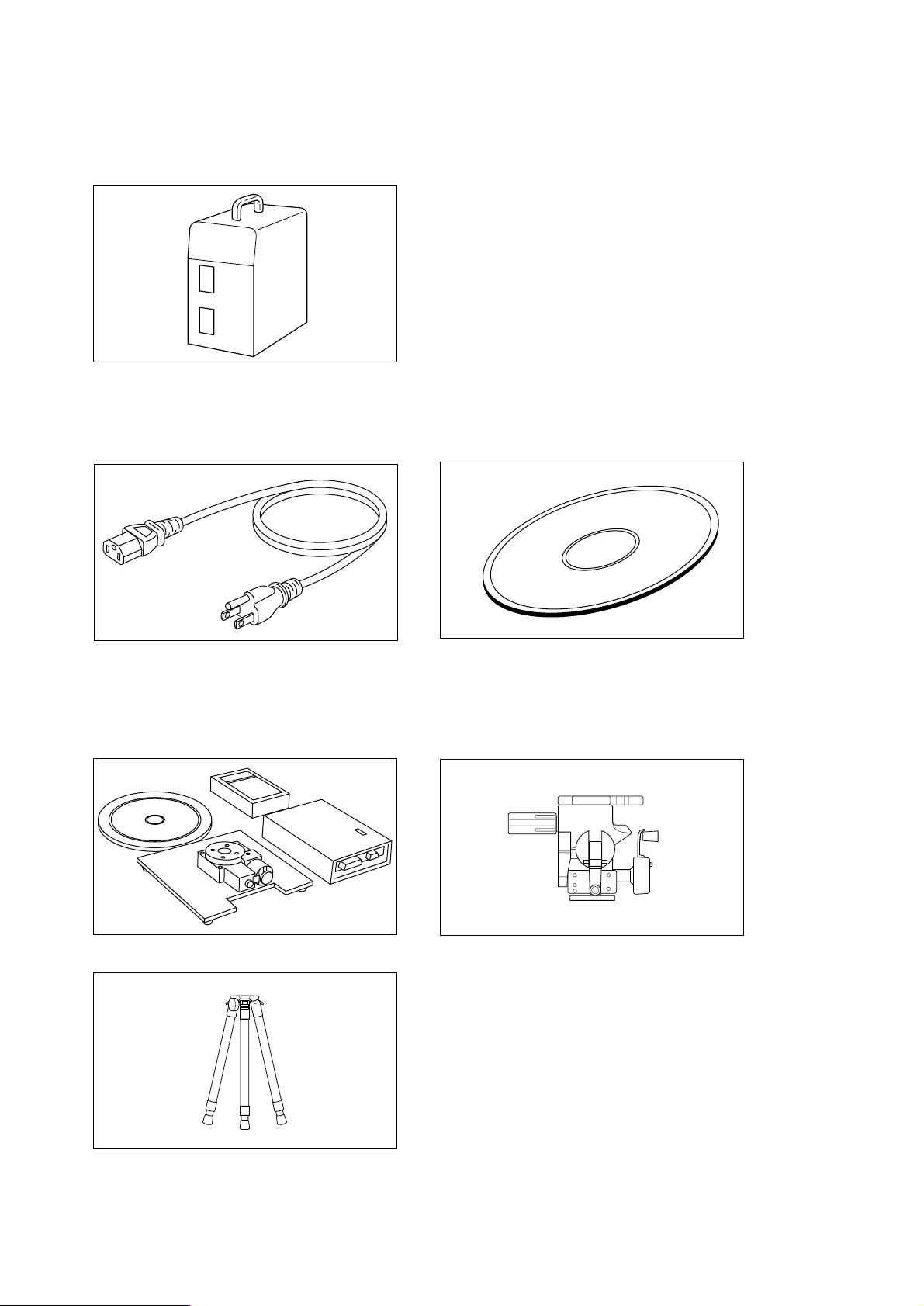
ACCESSORIES
Check that the following standard accessories are present.
VIVID 300 MAIN BODY
ST ANDARD ACCESSORIES
AC POWER CORD UTILITY SOFTW ARE VI-S1
OPTIONAL ACCESSORIES
The following are optional items, so they must be purchased if needed.
ROT ATING ST AGE SET PANHEAD CS-A4
TRIPOD CS-A3
SCSI Cable VI-A20 (Half-pitch, D-Sub, 50-pin male plug on both ends)
Joint MM-A14 (for rotating stage)
SCSI Conversion Connector: VI-A21 (50-pin female ↔ 68-pin male)
4
Page 7

SYSTEM CONFIGURATION
AC Power Cord
Panhead CS-A4
VIVID 300 Main Body
Utility Software
VI-S1
SCSI Cable VI-A20
Host Computer
Tripod CS-A3
Rotating Stage Set MM-60 S
θ
Standard accessory
Optional accessory
A commercially available
computer can be used as
the host computer.
5
Page 8

NAMES OF PARTS
Laser Emitting Window
A laser beam is emitted from this window.
Do not stare into this window.
Output T erminal for
External Monitor
SCSI Port
Power Switch
DIP Switch
(ID Selector)
Tripod Socket
AC Power Connector
6
Page 9

CONNECTING THE AC POWER CORD
WARNING
Always use the AC power cord supplied as a standard accessory with the VIVID 300, and connect it to an AC outlet
(100-240 V~, 50-60 Hz). Failure to do so may damage the VIVID 300, causing a fire or electric shock.
Do not bend, twist or pull the AC power cord excessively. Do not place heavy items on the AC power cord, or
damage or modify it in any way. Doing so may cause damage to the AC power cord, resulting in fire or electric
shock.
If the VIVID 300 will not be used for a long time, disconnect the AC power cord from the AC outlet. Accumulated dirt
or water on the prongs of the AC power cord’s plug may cause a fire. Any dirt or water on the prongs of the AC power
cord’s plug must be removed.
When disconnecting the AC power cord’s plug, always hold the plug and pull it to remove it. Never pull the AC power
cord itself. Doing so may damage the AC power cord, causing a fire or electric shock. Do not insert or disconnect
the AC power cord’s plug with wet hands. Doing so may cause electric shock.
CAUTION
For Continued protection against risk of fire or electrical shock a mains plug shall connect to grounding-type socket
outlet.
Before connecting the grounding terminal, make sure that the AC power cord is not connected to the AC outlet.
Failure to observe this may cause electric shock.
The socket-outlet shall be installed near the machine and shall be easily accessible.
Connecting Method
1. Set the POWER switch on the side panel of the VIVID 300 to the
OFF “䡬”.
If the AC power cord is connected to an AC outlet with
the POWER switch set to ON “I”, damage to the VIVID
300 or host computer may result.
2. Plug the AC power cord to the AC power connector (AC IN) on the
side panel.
3. Plug the other end of the AC power cord to an AC outlet.
7
Page 10

CONNECTING THE VIVID 300 TO A HOST COMPUTER
The VIVID 300 is designed to be operated from a host computer using utility software. Before operating the VIVID 300,
make sure that it is connected to the host computer with an optional SCSI cable.
CAUTION
The host computer must be operated correctly and safely according to its instruction manual.
䡬 The optional SCSI cable (VI-A20) has a 50-pin male plug (half-pitch, D-Sub) on both its ends.
● Before turning the host computer ON, make sure that the VIVID 300 is turned ON and ready for operation.
Connecting Method
1. Set the POWER switch of both VIVID 300 and host computer to
OFF “䡬”.
If the VIVID 300 is connected to the host computer with
the POWER switch set to ON “I”, damage to the VIVID
300 or host computer may result.
2. Plug the SCSI cable to a SCSI port of the VIVID 300.
3. Plug the other end of the SCSI cable to the SCSI connector of the
host computer.
◆ The VIVID 300 is now connected to the host computer.
● When you select [Control Panel] – [SCSI Adapters] and then click the [Devices] tab, “Minolta VIVID700” will be dis-
played as the device name. Please note that “Minolta VIVID700” is displayed instead of “Minolta VIVID300”.
8
Page 11

MAKING SCSI SETTING
Make the following settings according to the SCSI settings made on the host computer and peripheral devices you are
using. Once they are made, it is not necessary to make them again.
Setting the DIP Switch (SCSI ID)
DIP switches (ID selector) are provided on the rear panel for the following settings:
Set the SCSI ID.
Switch the terminator ON/OFF.
ON
21
Setting the SCSI ID No.
In order for the host computer to recognize that the VIVID 300 is connected to the host computer via the SCSI interface, a
SCSI ID No. (1 to 6) must be set for the VIVID 300.
䡬 SCSI ID No. 5 has been set as the default setting before shipment.
● If other SCSI devices are connected to the host computer via the SCSI interface, make sure that the SCSI ID No. of the
VIVID 300 differs from those set for the devices.
Setting Method
1. Make sure that the POWER switch of both VIVID 300 and host
computer are set to OFF “䡬”.
543
Turn ON/OFF the power to the terminator.
2. If other SCSI devices are connected to the host computer via the
SCSI interface and are currently used, make sure that the SCSI
ID No. of the VIVID 300 differs from those set for the devices.
● For a description of how to check the SCSI ID, refer to the manual supplied with the SCSI interface board.
● If the currently set SCSI ID No. of the VIVID 300 is already used by other devices, proceed to the next step 3 and set a
unique SCSI ID No. using the DIP switches SW1 to 3.
If not, skip to step 4.
9
Page 12

3. Refer to the table below and set a unique SCSI ID No. using the DIP switches SW1 to 3.
● If other SCSI devices are already connected to the host system via the SCSI interface, make sure that a SCSI
ID No. other than those set for those devices is set.
SCSI ID
0
1
2
3
4
5
6
7
4. Use the DIP switches SW4 and SW5 to set whether the terminator is to be used or not and whether power is to be
supplied to the terminator.
Terminator
Terminator power
SW1
OFF
ON
OFF
ON
OFF
ON
OFF
ON
Enabled
Disabled
Supplied
Not supplied
SW2
OFF
OFF
ON
ON
OFF
OFF
ON
ON
SW4
ON
OFF
SW3
OFF
OFF
OFF
OFF
ON
ON
ON
ON
SW5
ON
OFF
Setting the T erminator
The VIVID 300 has a built-in SCSI terminator. The terminator is needed if the VIVID 300 is the last device of those
connected in series to the SCSI interface. If only one of the SCSI ports on the VIVID 300 is used, “Enabled” or “Disabled”
must be selected correctly.
● If the VIVID 300 is not the last device of those connected in series to the SCSI interface or if it is not connected via the
SCSI interface, “Disabled” must be selected.
䡬 “Enabled” has been selected as the default setting before shipment.
If the terminator is not set correctly , the VIVID 300 or devices connected to the SICI interface may malfunction.
T urning ON/OFF the Power to the Terminator
SW5 is used to decide whether power is to be supplied to the terminator. For details, refer to the manual that comes with
the SCSI interface board.
● Set SW5 to ON (Supplied) if you are going to connect the VIVID 300 to a Laptop computer, or set it to OFF (Not
supplied) if you are going to connect the VIVID 300 to a desktop computer.
10
Page 13

TURNING POWER ON/OFF
Turning Power ON
1. Set the POWER switch of the VIVID 300 to ON “I”.
2. Set the POWER switch of the host computer to ON.
◆ The VIVID 300 is now ready for operation.
When turning the power ON after it has been turned OFF , wait at least 5 seconds before turning the power ON. Failure
to do so may result in malfunction.
T urning Power OFF
1. Set the POWER switch of the host computer to OFF.
2. Set the POWER switch to OFF “䡬”.
◆ The power will be turned off.
11
Page 14

CONNECTING AN EXTERNAL MONITOR
T o connect an external monitor to the VIVID 300, use a suitable co-axial cable (the cable must have a BNC terminal (75 Ω)
on the end which is to be connected to the VIVID 300).
● Only the NTSC type monitor can be used (PAL and other types cannot be used).
Connecting Method
1. Set the POWER switch of both VIVID 300 and external monitor to
OFF “䡬”.
If the VIVID 300 is connected to the monitor with the
POWER switch set to ON “I”, damage to the VIVID 300
or monitor may result.
2. Connect the BNC plug of the co-axial cable to the output terminal
for external monitor (MONITOR) of the VIVID 300.
3. Connect the other end of the cable to the VIDEO terminal of the
external monitor.
◆ The VIVID 300 is now connected to the external monitor.
● Set the POWER switch of the VIVID 300 to ON “I”. The
same views and images currently displayed on the viewfinder will appear on the external monitor.
12
Page 15

Replacing the Fuse
To prevent disaster such as fire, a fuse which conforms to the following requirements must be used.
Usable fuses ........ T2A 250V type
WARNING
When replacing the fuse, first turn the power OFF, disconnect the AC power cord from the AC outlet, then replace it
with one which conforms to the required specifications. Failure to do so may result in electric shock. If the fuse blows
off soon after it has been replaced, contact the nearest Minolta-authorized service facility.
Replacement Procedure
1. Set the POWER switch to OFF , then disconnect the AC power cord
from the AC outlet.
2. Place a flat-blade screwdriver on the fuse holder as shown, and
pull it toward you to remove the holder.
3. Replace the fuse with a new one and set the fuse holder in place.
◆ If the fuse blows off soon after it has been replaced, disconnect the AC power cord from the AC outlet, then contact the nearest Minolta-authorized service facility.
Spare fuse
13
Page 16

MEASURING PRINCIPLE
The VIVID 300 uses the light-stripe method to emit a horizontal stripe light through a cylindrical lens to the object. The
reflected light from the object is received by the CCD, and then converted by triangulation into distance information. This
process is repeated by scanning the stripe light vertically on the object surface using a galvano mirror, to obtain a 3D
image data of the object.
Galvano Mirror
Object
Lens
Laser
High-Speed Image Processing Circuit
The VIVID 300 uses a CCD which can be operated in 2 modes (charge output and charge drain modes), to enable highspeed acquisition of range images.
After 1-frame CCD exposure, among the signal charges transferred to the memory, only those of the reflected light from
the object surface are extracted by block readout while the other signal charges are drained at once.
The stripe light is scanned on the CCD image plane at one horizontal line per frame and the CCD is driven so that the block
readout start position is shifted one line per frame, to acquire a total of approximately 250 frames of the image.
(CCD driving rate: 14.3 MHz, block readout: 38 lines, data acquisition speed: 0.6 seconds)
The output signal from the CCD is then sent to the analog processing portion, where it is amplified and subjected to
waveform processing. It is then converted into a digital signal (i.e., image data) and saved in the frame memory .
Frame Interline
Transfer CCD
CCD Driver
Sample/Hold
Clock Generator
amp
Sync, Sample clock,
Counter control
Analog
Processing
A/D
Image
Processor
Frame
Memory
Host I/F
14
Galvano
Scanner
Laser Diode
Driver
CPU
CPU data bus
Page 17

DIMENSION DIAGRAM
406
353
(Unit: mm)
320165
15
Page 18

SPECIFICATIONS
Model Name VIVID 300/VI-300
Light-Receiving Lens f = 12 mm
Laser Power λ = 690 nm, Max. 7 mW
(Class I or equivalent, controlled and emitted by the internal control
circuit and optics)
Beam Spread Angle (2σ) Horizontal : 23.7°
Vertical : 0.1°
Laser Scanning Method Galvano mirror
Object Distance Range 0.55 to 1.2 m
Field of View (each side of field of view xy) 185 to 395 mm
Operative Distance Range (
Scanning Time 0.6 sec.
Image Data Transfer Time to Host Computer 2.0 sec. or less
Ambient Lighting Condition 500 lx or less
Imaging Device 3D data : 1/2-inch frame transfer CCD (380,000 picture elements)
Output Data Points 3D data : 200 × 200
Save/Output Format 3D data : Original format (converted to 3D data by the utility software
Output Interface SCSI II, color monitor NTSC terminal
Power 100 to 240 V
Fuse Type T2A 250V
Dimensions 165 (W) × 406 (H) × 320 (D) mm
Weight 8 kg
Operating Temperature Range 10 to 35°C (85% relative humidity or less, no condensation at 35°C)
Storage Temperature Range -20 to 50°C (85% relative humidity or less, no condensation at 35°C)
z) Equivalent to each side of the field of view (when image input distance
is 1.2 m)
Color data: 1/2-inch color CCD (380,000 picture elements)
Color data: 400 × 400
VI-S1)
Color data: RGB 24-bit raster scan data
~
(50 to 60 Hz), 0.6 A (rated 100 V~)
16
Page 19

Page 20

2000 Minolta Co., Ltd. under the Berne
9222-1884-11 AAKAR1 Printed in Japan
Convention and Universal Copyright Convention
 Loading...