

Page 1

Konica NT RIP
Getting Started
Guide
AAddddiittiioonnaall ddooccuummeennttaattiioonn ccaann bbee
ffoouunndd iinn tthhee DDooccuummeennttaattiioonn ffoollddeerr
oonn yyoouurr KKoonniiccaa RRIIPP CCD
D
AG12333P3 Rev. 12 Konica NT RIP Getting Started
Page 2

Konica NT RIP Getting Started Guide
This guide reflects the Konica NT RIP Getting Started Guide as of September 2004.
© copyright Konica Incorporated 2004
Proprietary Notice
The information contained within this guide is the property of ECRM. No transmission,
reproduction, transcription, storage in a retrieval system, translation into any language or
other use is permitted in whole or in part in any form without first obtaining written
permission of ECRM.
Konica® is a registered trademark of ECRMKonica Corporation. ECRM® is a registered
trademark of ECRM Incorporated Other brand or product names are the registered
trademarks or trademarks of their respective holders.
ii
Konica NT RIP Getting Started AG12333P3 Rev. 12
Page 3

Contents
. . . . . . . . . . . . . . . . . . . . . . . . . . . . . . . . . . .
Introduction 1
Recommended System Configuration 1
Backup Utilities 3
Connecting the Pieces 3
Installing the SCSI Cable 4
Installing the Encryption Key (Dongle) 4
Turning on the System 4
Power on the Recorder 4
Power on the NT/ 2000 Workstation 4
Technical Support 5
Installing the RIP 6
RIP Upgrade Installation 6
New RIP Installation 6
Ensure AppleTalk is Installed before Running the RIP 11
Configuring the RIP 12
Launching the RIP from the RIP Workstation 12
The Configure RIP Window 14
Configuring RIP Extras 15
Cassette Manager 17
Page Setup Manager and “Page Setups” 18
Separations Manager 21
Configure Device 24
Saving Page Setup 32
Setting Page Setup Exposure Value 33
Exposure Sweep Jobs for the EV-jetsetter 9200 33
Exposure Sweep Jobs for All Other Recorders 36
Calibration 37
. . . . .
. . . . .
AG12333P3 Rev. 12 Konica NT RIP Getting Started iii
Page 4

Outputting an Image 41
Media Manager 42
Uninstalling the RIP 42
iv
Konica NT RIP Getting Started AG12333P3 Rev. 12
Page 5

T
HE
R
IP
S
OFTWARE
. . . . . . . . . . . . . . . . . . . . . . . . . . . . . . . . . . .
INTRODUCTION
. . . . . . . . . . . . . . . . . . . . . . . . . . . . . . . . . . . . . . . . . . . . . . . .
This document outlines how to install the hardware, install the RIP,
configure the RIP, and output a a calibrated file on a Windows NT,
Windows 2000, or Windows XP system.
RECOMMENDED SYSTEM
CONFIGURATION
. . . . . . . . . . . . . . . . . . . . . . . . . . . . . . . . . . . . . . . . . . . . . . . .
Recommended Platform Specifications
• Pentium 4.2ghz or faster processor
• At least one 40gb or larger disk drive with a minimum spindle speed
of 7200 rpm
- Older, slower computers may require two SCSI disk drives
- More files, larger files or higher resolution will require more
disk space
• 512mb RAM or more
- Minimumof lgb of RAM if TrapPro or TrapProLite are
enabled
- No applications other than ECRM RIP and CTServer allowed
on platform
• Operating Systems (all operating systems must be properly
configured)
- Windows XP Professional, Service Pack I or higher*
- Windows 2000 Professional, Service Pack 3 or higher*
- Windows NT 4.0, Service Pack 5 or higher*
- Windows 2003 Server
• Adaptec 2930 SCSI adapter
• CD ROM Drive
• Parallel Port
. . . . .
AG12333P3 Rev. 12 Konica NT RIP Getting Started
1
Page 6

Recommended System Configuration
Note:
Note:
Note:
Note:
* For Mac connectivity, Windows Server or third party Mac connectivity
software, such as PC MacLAN, is required
A sustained formatted data read rate of 12mb/sec. is specified to insure
the drive is sufficiently fast to supply data to the recorder.Not all manufacturers supply this information in their literature. Fast drives with
spindle speeds of 10,000 RPM or more typically are sufficient.
•For EV-jetsetter 6200, 6250, 5200, 9100, 6100 and 9200 a high voltage
differential SCSI card, such as the Adaptec 2944, is required.
Some recorders are equipped with traditional SCSI and some are
equipped with differential interfaces and are not directly compatible
with LVD or Ultra2 SCSI adapters. If the recorder is differential, either
a single-ended to differential converter box connected to the recorder is
required, or, alternatively, the SCSI adapter attached to the recorder
must be differential.
•
Operating System:
2000 (Service Pack 2.0 or higher), or Windows XP Professional.
Windo ws NT 4.0 (Service P ack 6.0 or Higher), W indo ws
The ECRM Konica RIP runs on Microsoft Windows NT 4.0/2000/XP
Workstations and NT 4.0/2000/XP Servers. If you wish to have Macintosh clients submit jobs directly to the RIP, you will need NT/2000
Server or alternative connectivity software such as PC MacLan by
Miramar.
•
Note:
CD ROM drive:
•
NT Configuration:
that the network is optimized. In the NT Control
Panel>Network>Services>Server>Configuration dialog, “Balanced” check
box must be chosen. In Windows 2000, Select My Network
Places>Properties>Local Area Connection>Properties>File and Printer
Sharing for Microsoft Networks>Properties and then select “Balanced”.
•
Adaptec SCSI Driver:
or later.
•
Rip Configuration:
for system should be 64,000 KB or more. The Network buffer should be
4096KB. The Band size for printing buffer should be 256KB.
Host requirements can vary depending on model of recorder, r esolution,
One is required.
If NT/2000 Server (not Workstation) is in use, make sure
The Adaptec aic78xx.sys driver must be version 2.3
Printer buffer 8192KB or more. Minimum memory left
image size, and other items. It is highly recommended that you consult
with your Dealer/Representative with regard to the minimum system
2
Konica NT RIP Getting Started AG12333P3 Rev. 12
Page 7

configuration that will best meet your needs.
. . . . .
BACKUP UTILITIES
. . . . . . . . . . . . . . . . . . . . . . . . . . . . . . . . . . . . . . . . . . . . . . . .
The utilities
Utils folder, which is in the
BackupConfiguration.ps
and the
utilities are postscript files, they are printed directly through the RIP
via the Print File menu. When printed, each of these utilities creates a
file in the
Config.ps
While these utilities run, the RIP Monitor registers which files are
being backed up and displays the paths where these files reside, in case
you need to restore the information from these files.
To restore the information from these backup files, print the postscript
files through the RIP via the Print File menu. To restore the Font Data
information print
Config.ps
restored. To use, quit and relaunch the RIP after restoring
configuration.
BackupConfiguration.ps
ECRM Konica RIP
utility backs up the RIP Configuration Data
Backupfonts.ps
Utils
folder.
and
Backupfonts.ps
. The RIP Monitor also registers which files are being
utility backs up the RIP Font Data. Since these
BackupConfiguration.ps
creates a file called
Fonts.ps
and to restore the Configuration Data print
and
Backupfonts.ps
are in the
folder. The
creates a file called
Fonts.ps
.
Once you install the RIP and supply it with information, such as
additional fonts, page setups, and calibration sets, create a backup of
the RIP. Also, periodically backup the RIP data as you add or delete
RIP information. The files
time you back them up.
Note:
AG12333P3 Rev. 12 Konica NT RIP Getting Started 3
These backup utilities have not be tested for all versions of the NT RIP,
therefore, they may not operate correctly with earlier versions.
Config.ps
and
Fonts.ps
are overwritten each
Page 8

Connecting the Pieces
CONNECTING THE PIECES
. . . . . . . . . . . . . . . . . . . . . . . . . . . . . . . . . . . . . . . . . . . . . . . .
How to interconnect the recorder and the host.
Installing the SCSI Cable
With the NT/2000/XP workstation and recorder powered off, connect
the SCSI cable, AC280015 or AC24628, from the SCSI port of the
workstation to the bottom port of the recorder. If you have two SCSI
controller cards, refer to the documentation that came with your
workstation for the proper SCSI controller card location used for the
recorder connection.
Installing the Encryption Key (Dongle)
With the NT/200/XP workstation and recorder po wered of f, install and
secure the encryption key (dongle) provided with the RIP software kit.
There are two types of dongles: parallel and USB. The parallel dongle
works on NT, Windows 2000, and XP workstations. However,
USB dongle works only on Windows 2000 and XP workstations.
The parallel dongle must be installed on a parallel printer port on the
NT/2000/XP workstation. The USB dongle must be installed on a
USB port of the Windows 2000/XP workstation.
the
TURNING ON THE SYSTEM
. . . . . . . . . . . . . . . . . . . . . . . . . . . . . . . . . . . . . . . . . . . . . . . .
Power on the Recorder
Once the recorder is powered on, verify that the recorder is on-line and
in serial mode. This can be done through the Control Panel of the
recorder.
Some recorder models take up to a minute to go on line after power is
turned on. On these models, be sure that the front panel is displaying
the following message
ONLINE - SERIAL
4
before
starting up your computer:
Konica NT RIP Getting Started AG12333P3 Rev. 12
Page 9

POWER ON THE NT/ 2000 WORKSTATION
Power on the NT/ 2000 Workstation
WARNING!
When booting the preinstalled operating system for the first time, you
!
Note:
must fill in the registration dialog window with Machine and Company
Name. Otherwise , y ou will ha ve to reinstall the operating system from
the beginning.
Step 1 Boot the NT / 2000 / XP workstation by turning the power on.
Step 2 Let the boot sequence automatically boot into Windows NT / 2000. Do not
select Enter and do not activate other menus unless instructed to do so by
an authorized dealer.
The password in the Welcome window will be blank on boot up. Refer to
your Windows NT / 2000/ XP manual for information on establishing
passwords.
TECHNICAL SUPPORT
. . . . . . . . . . . . . . . . . . . . . . . . . . . . . . . . . . . . . . . . . . . . . . . .
If you need technical support, call your service representative or the
dealer from whom you bought your Konica system.
Before calling for support:
. . . . .
Step 1 Make sure your hardware meets the system requirements defined in the
document.
Step 2 Make sure all cable and peripheral connections are correct and secure.
Step 3 Read any release notes shipped with your system.
Step 4 Record exactly any system error messages that appear on boot up or any
RIP monitor error messages. If possible, send your representative a copy
of the file, LOGFILE, found in the SW folder of your RIP.
AG12333P3 Rev. 12 Konica NT RIP Getting Started 5
Page 10

Installing the RIP
INSTALLING THE RIP
. . . . . . . . . . . . . . . . . . . . . . . . . . . . . . . . . . . . . . . . . . . . . . . .
This section outlines how to install a new RIP, upgrade an e xisting RIP,
and uninstall an existing RIP.
RIP Upgrade Installation
If installing the RIP for the first time, proceed to the RIP Installation
instructions listed on page 6. If upgrading from a previous RIP,
continue to the section below.
UPGRADING
Page setups, fonts, calibration sets and cached screens are not forward
compatible when upgrading from one RIP to another. Therefore,
perform the following before installing the new RIP on your existing
platform:
Step 1 Launch your existing RIP and record the data for all your page setups and
calibration sets which you wish to keep.
Step 2 Perform List Fonts from the Fonts menu to get a list of all the fonts
currently installed in the RIP. This list of fonts is registered in the LOGFILE.
Print the LOGFILE, which is located in the SW folder, using a text editor.
Using the LOGFILE you will know which fonts need to be reinstalled aside
from the base fonts that are present in the RIP by default.
Step 3 Proceed to the RIP Installation instructions listed on page 6 to install the
RIP. Once the RIP has been successfully installed, you will have to
recreate the page setups and calibration sets and reinstall fonts. You may
wish to delete the old RIP folder at this time. Refer to “Uninstalling the
RIP" on page 43.
New RIP Installation
Note:
You will have to use a log-on that has ‘Administrator’ privileges in order
to install all the components. Otherwise, all the drivers may not install
correctly.
6
The RIP will create new cached screens as jobs are interpreted.
The RIP Installer installs all the RIP software, the Sentinel Driver
required for the Dongle, and the
Scsipel.sys
Driver required to
drive the recorder. To install the RIP and the Drivers, do the following:
Konica NT RIP Getting Started AG12333P3 Rev. 12
Page 11
NEW RIP INSTALLATION
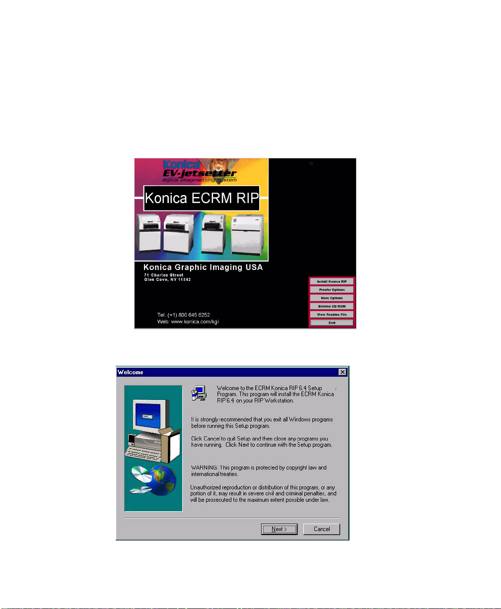
Step 1 Insert the RIP CD into the CD ROM drive of y our computer. (If your system
is set to run an autorun file, steps 2 through 4 will automatically be
performed).
Step 2 Double click on < my computer > on the desktop.
Step 3 Double click on the < RIP > CD icon.
Step 4 Double click on, or launch, the
Setup.exe
program.
•The Konica ECRM RIP splash screen displays.
Step 5 Click the Install Konica ECRM RIP button on the splash screen.
•The welcome window displays.
. . . . .
AG12333P3 Rev. 12 Konica NT RIP Getting Started 7
Page 12
Installing the RIP
Step 6 Read the information provided and Click Next.
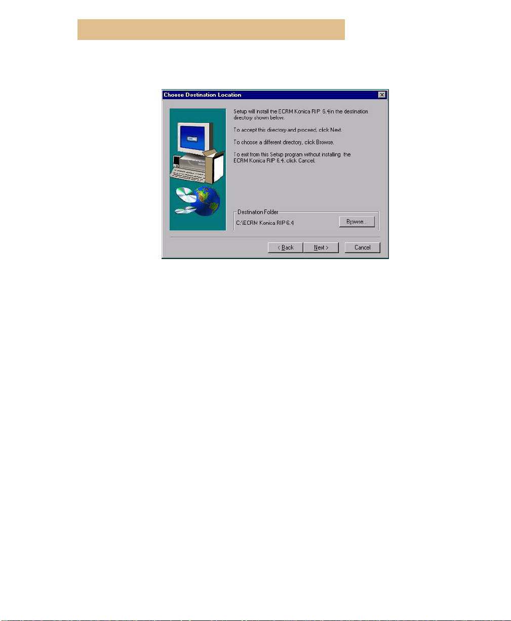
Step 7 Click Next to accept the default destination drive and folder or click
•The Choose Destination Location window displays.
Browse to open a browser window where you may enter a different
destination drive and folder.
Note:
If upgrading from an existing RIP and you ha ve not deleted the old RIP,
you will need to change the folder name f or the new RIP to a name other
than the old RIP folder name.
Step 8 Click Next.
8
Konica NT RIP Getting Started AG12333P3 Rev. 12
Page 13
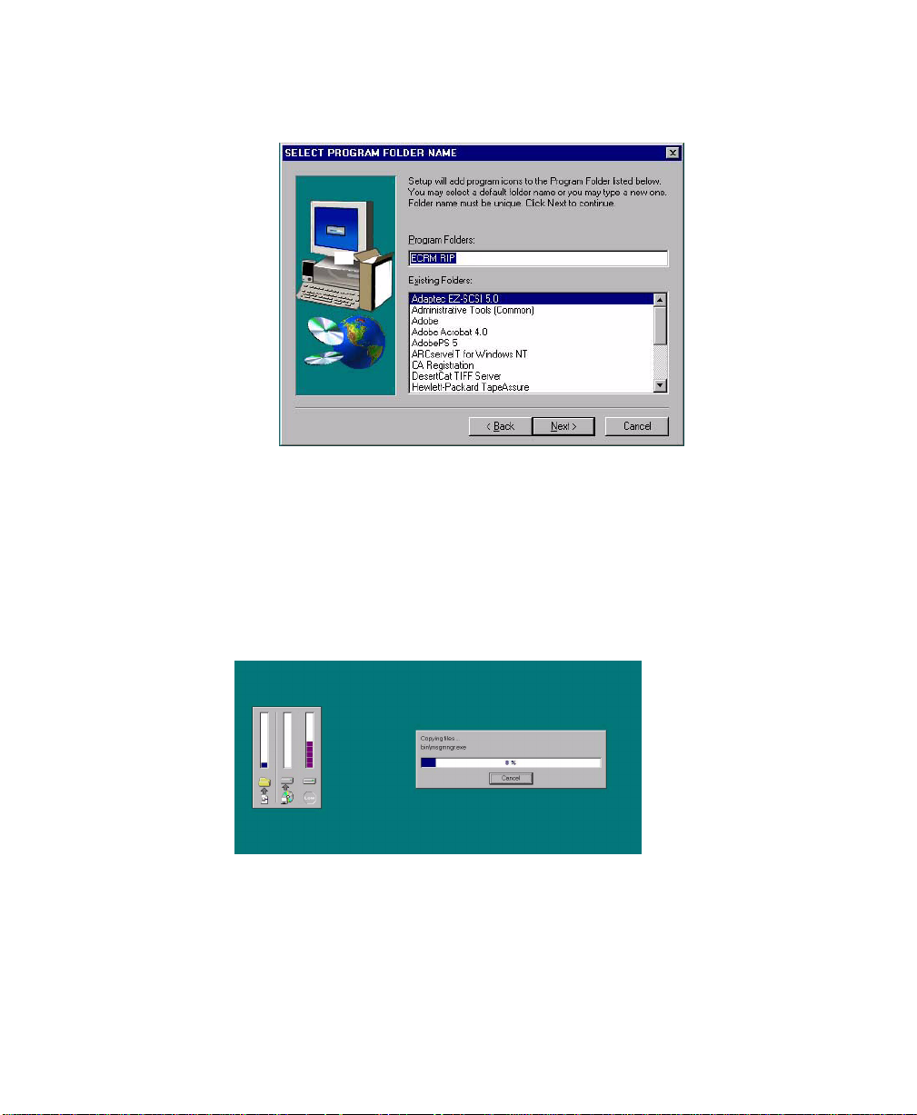
NEW RIP INSTALLATION
•The
SELECT PROGRAM FOLDER NAME
“ECRM Konica RIP 6.4” appearing as the default program folder name.
Step 9 If the default name in the box is acceptable, click Next. Otherwise, enter a
different name (like ECRM RIP as shown above).
Step10 If the program folder name presented in the Program Folders: box is not
acceptable, you may enter a name in the box, or you may click on an
existing name in the Existing Folders: box.
Step11 Click Next.
•An installer screen opens and tracks the progress of the installation of the
software.
window displays, with
. . . . .
AG12333P3 Rev. 12 Konica NT RIP Getting Started 9
Page 14
Installing the RIP
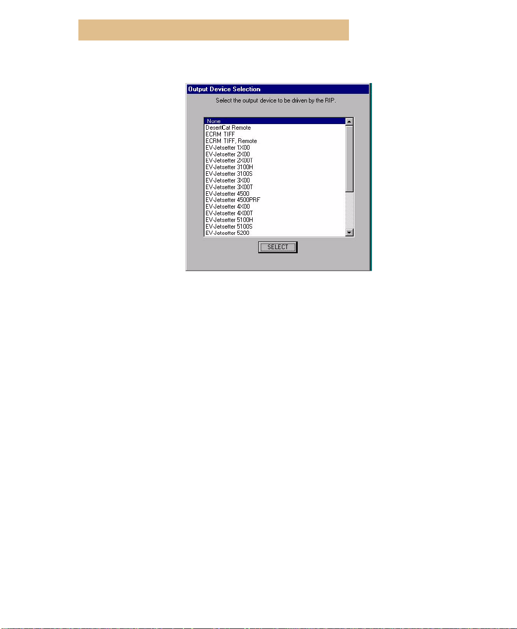
Note:
•Eventually , the
a list of available devices. The list contains the recorders supported by the RIP.
•Additionally, the list has selections for “ECRM TIFF”, “ECRM TIFF,
Remote” and “DesertCat, Remote”. These selections are to be used when the
RIP is to generate TIFF files and send them to CtServer or DesertCat Queue.
Selecting these output devices insures all the necessary information for these
devices is included in the TIFF file.
Physical Output Device Selection
window displays with
If this RIP will be sending TIFF files, either over the network or on the
same workstation, to DesertCat Queue for output to a DesertCat, select
“DesertCat, Remote”.
Note:
If this RIP will be sending TIFF files to ECRM CtServer on the same
workstation, select “ECRM TIFF”. If this RIP will be sending TIFF files
to ECRM CtServer over the network, select “ECRM TIFF, Remote”.
Step12 Use the scroll bar to scroll to the correct recorder model, and click the
SELECT button.
10
Konica NT RIP Getting Started AG12333P3 Rev. 12
Page 15
NEW RIP INSTALLATION
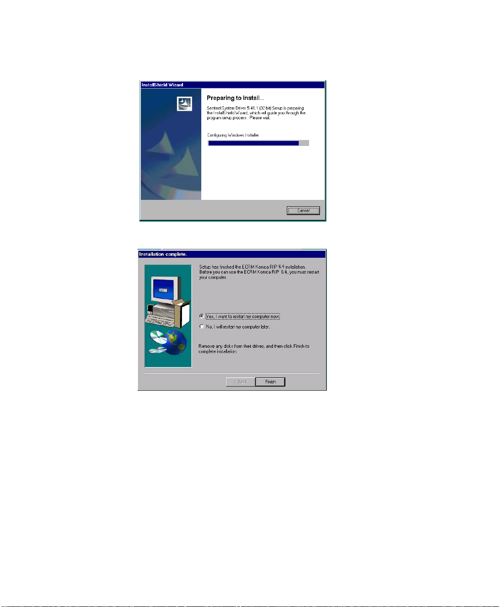
•The The Sentinel Driver Installation displays and tracks the installation of the
driver.
•Eventually, the Installation Complete window displays.
. . . . .
Step13 Select Yes or No as an answer to the question: “Do you want to restart
your computer?”.
Note:
Note:
You must restart your computer before using the RIP.
Be sure the imagesetter is connected and powered up prior to powering
on the PC.
Step14 Remove the installation CD ROM from the drive.
Step15 Click Finish to restart your computer.
Note:
When the system restarts, you may see an error message about an
unsupported driver being installed. Ignore the message and click on OK
to clear it.
AG12333P3 Rev. 12 Konica NT RIP Getting Started 11
Page 16

Installing the RIP
Ensure AppleTalk is Installed before Running the RIP
Appletalk must be installed on your system if the RIP is to run
correctly. On Windows NT and Windows 2000, AppleTalk is installed
by default in the network settings of the computer. If you have
removed AppleTalk from your Windows or Windows 2000 system,
you must reinstall it before starting the RIP.
Windows XP does not contain the AppleTalk protocol. However,
ECRM has included AppleTalk protocols from Miramar Systems Inc.
on the RIP CD to provide Windows XP users with a convenient means
for purchasing and installing a licensed copy of Miramar AppleTalk.
If this procedure is not performed, you will see the following error
message when you launch the RIP:
‘
The procedure entry point SMAPLS_TP_EBP_9
could not be loaded in the Dynamic Link Library
Kernal 32.dll.”
To install the Miramar AppleTalk protocols on a Windows XP system:
Step 1 Click “Start > Control Panel” and double-click “Network Connections.”
Step 2 Right-click “Local Area Connection” and then click “Properties.”
Step 3 On the “General Tab” click “Install.”
Step 4 Click “Protocol” and then click “Add.”
Step 5 Click to select “Miramar Systems Inc,” click “AppleTalk” from the protocol
list, and then click “OK.”
Step 6 Restart your computer to complete the installation.
Note:
12
When you restart your system and then start the RIP, you will be asked to suppl y
the Miramar password if you enable an input channel in the RIP. To obtain the
required password -- for whic h there is a charge -- contact ECRM. Once y ou enter
the correct password, you will not be asked to supply the password again.
Konica NT RIP Getting Started AG12333P3 Rev. 12
Page 17

LAUNCHING THE RIP FROM THE RIP WORKSTATION
CONFIGURING THE RIP
. . . . . . . . . . . . . . . . . . . . . . . . . . . . . . . . . . . . . . . . . . . . . . . .
This section takes you from launching the RIP to outputting a
calibrated image on your recorder. The final image you output should
be an actual job to verify the settings specified in the selected page
setup.
You can find detailed information about all the settings explained
briefly below in the RIP Operator Guide located on the RIP CD ROM.
Launching the RIP from the RIP Workstation
Step 1 Click the Start button and select Programs.
Step 2 Select ECRM RIP from the Programs menu.
Step 3 Select the RIP fr om the ECRM RIP men u. The RIP launches and the splash
screen displays.
. . . . .
Step 4 Click OK to continue.
AG12333P3 Rev. 12 Konica NT RIP Getting Started 13
Page 18

Configuring the RIP
•The Password dialog may appear.
Step 5 Enter the password from your dongle and click OK.
Note:
About passwords:
•If this is a new installation, then a password is not needed.
•If this is an upgrade from a 5.1, 5.3, or 5.5 RIP, then a password is required.
•If this is an upgrade from a 4.x RIP, then a password is needed.
•If this is an upgrade from a 5.1, 5.3, or 5.5 RIP, which was itself an upgrade
from a 4.x RIP, then a password is needed.
•When you receive RIP software, the password is located on the bottom of
your packing slip/invoice (If a password is required). If your password does
not appear on your invoice, call ECRM customer service (978-851-0207) with
your invoice number, and they will give you the correct password.
14
Konica NT RIP Getting Started AG12333P3 Rev. 12
Page 19

THE CONFIGURE RIP WINDOW
•Two RIP windows display: The Menu Bar, Output Controller, and Media
Monitor windows display.
The Configure RIP Window
The print and network buffers in the
to default values that should be adequate to operate the RIP software.
However, if a
Monitor
during output to the recorder, pull down from
Configure RIP>Options
for the system value.
Configure RIP...
printer caught-up
and increase the amount of memory left
window are set
error occurs in the
ECRM
RIP
RIP
. . . . .
to
Configuring RIP Extras
If you have purchased optional RIP extras, you must enable them by
entering the password provided.
Step 1 Click on ECRM RIP in the top menu, and click on Configure RIP from the
drop down menu.
AG12333P3 Rev. 12 Konica NT RIP Getting Started 15
Page 20

Configuring the RIP
•The
Step 2 Click on the Extras button.
•The
Configure RIP
window displays.
Configure RIP Extras
window displays.
Step 3 Use the scroll bar to select an option (for example, TrapPro) and click on
the ADD button.
16
Konica NT RIP Getting Started AG12333P3 Rev. 12
Page 21

CONFIGURING RIP EXTRAS
•The
Enable Feature
Step 4 Enter the password provided for your option.
Note:
The password for the old Harlequin ICC Profile Processor (HIPP)
window displays.
option works for the new Harlequin ColorPro.
The password for the old Easytrap/T rapWorks option works f or the new
TrapPro Lite option.
Step 5 Click OK.
•The
Configure RIP Extras
TrapPro
plug-in.
window displays, with
Yes
applied to the
. . . . .
Step 6 Click OK. The plug-in is now available for use.
AG12333P3 Rev. 12 Konica NT RIP Getting Started 17
Page 22

Configuring the RIP
Cassette Manager
Note:
Use the Cassette Manager to create cassette names and to attach values to
them that provide information to the RIP. For your con v enience, gi v e the cassette a name that you can easily recognize in the future. When you change
cassettes, the RIP has access to important information about that cassette:
e.g. the width of the media and the amount of media remaining in the cassette.
Note:
You do not need to use the cassette manager for cut-to-size imagesetters.
Step 1 In the main menu bar, pull down from Output to Cassette Manager.
•The
Cassette Manager
Step 2 Set Units: to your preferred unit of measure. Any values displayed are
changed to the new unit of measure.
Step 3 Click on the New button.
•The
New Cassette
window displays.
dialog box displays.
Step 4 First: before setting any numeric entries, set Units: to your preferred unit
of measure, if necessary.
Step 5 Name the cassette in a way that is easily identifiable.
18
Konica NT RIP Getting Started AG12333P3 Rev. 12
Page 23

PAGE SETUP MANAGER AND “PAGE SETUPS”
Step 6 Set Media Type: to a name that identifies the media contained in the
cassette.
Step 7 Set Media Width: to the width of the film in the units selected above.
Step 8 Set Remaining Length: to the amount of film in the cassette right now. If
you just installed a 200 foot roll, enter 200 feet. If you estimate that there is
47 feet left in an unknown cassette, enter that.
Note: Set length in the recorder to the same value or Cassette Manager will
reset to 0 after the first image is output.
Step 9 Number: is the identifying number of the cassette.
Step10 Click OK.
•The Cassette Manager window displays, with your new cassette listed by
name.
. . . . .
Step11 When finished, click the OK button in the Cassette Manager window.
Page Setup Manager and “Page Setups”
A Page Setup specifies parameters for the RIP to use in outputting to a
particular recorder. These parameters include the name of the recorder ,
the resolution in use, the calibration set required, and all other settings
needed to produce an acceptable output from the selected recorder
under the specified conditions. You will have one page setup for each
set of conditions (i.e. resolution, film type, etc.) under which you
output images.
In this section, you will create one page setup that reflects real
conditions at your location and you will output a calibrated image of
your choice.
The Page Setup Manager contains a list of the names of all page setups
that are currently installed in the RIP. As you create new page setups,
AG12333P3 Rev. 12 Konica NT RIP Getting Started 19
Page 24

Configuring the RIP
their names are added to the list. As your imaging requirements
change, you create new page setups or select existing ones to fit the
situation.
Step 1 In the main menu bar, pull down from ECRM RIP to Page Setup Manager.
•The Page Setup Manger window displays.
Step 2 Click on the New button.
•The New Page Setup dialog box displays.
Step 3 Set Output Device: to <your recorder name>.
20 Konica NT RIP Getting Started AG12333P3 Rev. 12
Page 25

SEPARATIONS MANAGER
Step 4 Set Resolution: to one that you use.
Step 5 Set Optimization: to None or Media Saving.
Step 6 Leave Exposure: set to its default value.
Step 7 Set Separation Style: Choose a default or create a new Separation Style.
Step 8 Color Options: Make no changes to Color Options.
Step 9 Leave Calibration:, Tone Curves:, Intended Press:, and Actual Press: set to
(None).
Step10 Set any effects that you plan to use such as Rotate, Negative, and
Mirrorprint.
Step11 Make sure Feature is deselected.
Step12 Leave Scaling: at 100% Vertical and Horizontal.
Step13 Select <your cassette> from the list presented by the Cassette: selection
box.
Step14 Make no changes to Page Layout...
Step15 Options: Enable “Abort job if any fonts are missing”. This prevents a job
imaging substituting “courier” for the missing font.
Separations Manager
The Separations Manager allows you to setup unique
configurations for individual page setups. You may use one of the two
defaults or create one of your own. One Style Name can be used for
more than one page setup.
. . . . .
Step 1 Select the icon for Separations, Screening and Color.
•The Separation Manager window displays.
Step 2 Select the name of y our recor der in the De vice field and highlight the style
name you wish to use.
AG12333P3 Rev. 12 Konica NT RIP Getting Started 21
Page 26

Configuring the RIP
Step 3 Click the Select button.
Step 4 Click New... if you wish to create a new separations page.
•The New Style dialog box displays
Step 5 Enter a unique Style Name:
Step 6 Select a Color Space:
Step 7 Output Format: is chosen automatically, depending on your Color Space:
selection.
Step 8 Clic k Create. Depending on Color Space: chosen, either a Monochrome or
a CMYK Edit Style dialog box appears.
22 Konica NT RIP Getting Started AG12333P3 Rev. 12
Page 27

SEPARATIONS MANAGER
Step 9 If you choose monochrome or RGB as your color space, this edit style
dialog box displays. Use Level 1 spot colors is grayed out and not
available for RGB.
. . . . .
AG12333P3 Rev. 12 Konica NT RIP Getting Started 23
Page 28

Configuring the RIP
Step10 If you choose CMYK as your color space, this edit style dialog box of
displays. Use Level 1 spot colors is available for CMYK.
Step11 Highlight any color and edit Print, Angle, or Ink fields, if needed. These are
located just below the separations box.
Step12 Click New to add a new spot color.
Step13 Select Override separations in job.
Step14 Select Use level one spot colors if applicable (grayed out f or monoc hr ome
and RGB color space).
Step15 Select Override angles in job, Reject preseparated jobs, and Recombine
preseparated jobs, if applicable.
Step16 Set Dot Shape: and select Override Dot Shape in job.
Step17 Set Frequency and select Override frequency in job.
Step18 Select Use Harlequin Precision Screening if desired, and make the
appropriate settings. See the RIP Operator Guide.
Step19 Select Use extra gray levels if desired and fill in Limit number of gray
levels to:
24 Konica NT RIP Getting Started AG12333P3 Rev. 12
Page 29

CONFIGURE DEVICE
Step20 Select Rotate screens according to page rotation.
Step21 Click OK.
•The Separations Manager window displays.
Step22 Click OK.
•The New Page Setup window displays.
. . . . .
Step23 Click Configure device... if not grayed out.
Note: The Device Configuration dialog box for your recorder displays. The
Configure Device Section explains each type.
Configure Device
There are five possible Configure device windows that you will see
depending on the type of recorder that you selected in the Output
device: entry: one for MAKO HT recorders, one for Cut-to-size
recorders, one for non Cut-to-size recorders, one for EV-jetsetter 9200
recorders, and one for DesertCat devices. Some recorders do not
require a Configure device window, in which case the Configure
device button is grayed out. Follow the directions below for your
recorder as identified by the illustration of the window.
AG12333P3 Rev. 12 Konica NT RIP Getting Started 25
Page 30

Configuring the RIP
MAKO HT RECORDERS
Figure 1. Device Configuration Window (Mako HT)
Step 1 First, set the Image Spacing units to your desired unit of measure, e.g.
inches.
Step 2 Set the image spacing value to the distance between images that you
want.
Step 3 Click the OK button.
Step 4 The Configure Device operation is complete for this type of recorder.
NON CUT-TO-SIZE RECORDERS
Figure 2. Device Configuration Window (Non Cut-to-size)
Step 1 First, set Distance Units to your desired unit of measure.
Step 2 Set Punches to: Both head and tail punches or Head punch only or No
punches. Note the explanatory graphic on the left side of the window.
Step 3 Set Head Punch / Distance to the distance you want between the
centerline of the head punch and the edge of the image.
26 Konica NT RIP Getting Started AG12333P3 Rev. 12
Page 31

CONFIGURE DEVICE
Step 4 Set Head Punch / Placement to Inside image or Outside image.
Step 5 Set Tail Punch / Placement to Inside image or Outside image or From head
punch.
Step 6 Set Tail Punch / Distance to the distance you want between the centerline
of the tail punch and the edge of the image or between the centerline of tail
punch and the centerline of the head punch.
Step 7 Finally, set Ima ge Spacing to the distance you want between the centerline
of the tail punch of one image and the centerline of the head punch of the
next. Note the explanatory note on the bottom left of the window.
CUT-TO-SIZE RECORDERS
. . . . .
Figure 3. Device Configuration Window (Cut-to-size)
Step 1 First, set Distance Units to your desired unit of measure.
Step 2 Set Punches to: Both head and tail punches or Head punch only or No
punches. Note the explanatory graphic on the left side of the window.
Step 3 Set Head Punch / Distance to the distance you want between the
centerline of the head punch and the edge of the image.
Step 4 Set Head Punch / Placement to Inside image or Outside image.
Step 5 Set Tail Punch / Placement to Inside image or Outside image or From head
punch.
AG12333P3 Rev. 12 Konica NT RIP Getting Started 27
Page 32

Configuring the RIP
Step 6 Set Tail Punch / Distance to the distance you want between the centerline
of the tail punch and the edge of the image or between the centerline of tail
punch and the centerline of the head punch.
Step 7 Finally, set Ima ge Spacing to the distance you want between the centerline
of the tail punch of one image and the centerline of the head punch of the
next. Note the explanatory note on the bottom left of the window.
Step 8 Select Cut to size for cut-to-size mode and deselect Cut to size for Galley
mode.
Step 9 If Cut to size is deselected, all items may be filled in exactly as for non cut-
to-size recorders.
Step10 If Cut to size is selected, Image Spacing is not read and you must set Top
Trim Margin and Bottom Trim Margin. The trim margins set the distances
from the centerlines of the head and tail punches to the cut lines. See the
explanatory graphic in the bottom left of the window.
EV-JETSETTER 9200 RECORDERS
Figure 4. Device Configuration Window (EV-jetsetter 9200)
Step 1 Set the exposure v alue to the value identified in the section titled
Sweep Jobs for the EV-jetsetter 9200
Step 2 Set the exposure sweep job settings to the exposure range and step
values. The sweep job will run in increments according to the step value.
Refer to the section titled
for details on running an exposure sweep.
28 Konica NT RIP Getting Started AG12333P3 Rev. 12
Exposure Sweep Jobs for the EV-jetsetter 9200
.
Exposure
Page 33

CONFIGURE DEVICE
Step 3 The Leading Punch (distance to leading edge of film) value default is the
preset Position. If additional positions are required enter the values,
separated by commas, in the other positions value box.
Step 4 The Trailing Punch (distance to leading edge of film) value default is the
Preset Position. If additional positions are required enter the values,
separated by commas, in the other positions value box.
Step 5 The A uxiliary Punch (distance to leading edge of film) value does not ha ve
a default value or preset. If Auxiliary punches are required enter the
values, separated by commas, in the other positions value box.
Step 6 Enter your preference in the Black Borders information field.
Step 7 Set your horizontal and vertical magnification. This feature provides for
limited resizing of the image by the recorder.
Step 8 Set your limit value for Black Borders.
. . . . .
AG12333P3 Rev. 12 Konica NT RIP Getting Started 29
Page 34

Configuring the RIP
DESERTCAT DEVICES
Step 1 In the output type inf ormation field select plotter to go direct via plug-in to
the DesertCat or Select the TIFF file format that is applicable in your
environment. Selecting a TIFF file, routes the plots through the DesertCat
Queue either on this PC or a PC on the network.
•The Output Folder information field has a default location assigned to it. This
output folder location has to be the same as the Watch Folder in the DesertCat
Queue. The RIP will then submit jobs to the DesertCat Queue.
This folder must be
the same as the Watch
Folder in the DesertCat
Queue.
Step 2 Enter the name of the output f older or c lick on the Output Folder button to
browse for the correct Watch Folder.
•The Media Type information field displays the media types that are available
to you. These media types have to be defined in the DesertCat Controller . Once
they have been defined, their names are written to the config.txt file in the
DesertCat Controller, and are read by the RIP. (The RIP must be restarted if
these media types have not been defined in the DesertCat Controller). Once the
30 Konica NT RIP Getting Started AG12333P3 Rev. 12
Page 35

CONFIGURE DEVICE
media types have been defined in the DesertCat Controller , restart the RIP, and
the RIP will then read them into this information field. If the RIP is on another
PC or network, the config.txt file must be copied to the RIP PC and placed in
the folder location where the RIP is installed. (example: C:\ECRM RIP
5.3\SW\devices\DesCat\setup)
Step 3 Clic k on the down arrow in the Media Type information field and select the
media type to be assigned to this page setup.
. . . . .
AG12333P3 Rev. 12 Konica NT RIP Getting Started 31
Page 36

Configuring the RIP
ECRM TIFF DEVICE
Step 1 Select the Property Set to which the TIFF files will be submitted. The
Property Set defines recorder settings to be applied to the job. These
settings include, media width, media type, punch settings, etc. See the
CtServer User Guide for details.
•The RIP will display all the Property Sets that are defined by the CtServer
installed on the workstation running the RIP as well as Property Sets defined
by CtServers on the network. Network Property Set names are displayed as
“MachineName:PropertySetName”. Based on the Property Set selected, the
RIP will know where to put the TIFF file.
Note:
Network Property Sets will not be visible until the Remote CtServer is
connected to via the CtServer Remote View, or the “Open” in the local
CtServer. After this connection, the RIP must be restarted to access the
Property Sets.
32 Konica NT RIP Getting Started AG12333P3 Rev. 12
Page 37

Saving Page Setup
Step 1 Click the OK button.
Step 2 Select Save As.
Step 3 Set Save As: to a name that identifies it easily. For instance, the name:
Step 4 Click Save.
SAVING PAGE SETUP
. . . . .
•The New Page Setup window displays.
•The Save Setup dialog displays.
1270-sq.-120 could mean 1270 resolution, square dot shape, and 120 line
screening frequency.
•The Page Setup Manager window displays, with your new Page Setup
listed.
Step 5 Click OK.
AG12333P3 Rev. 12 Konica NT RIP Getting Started 33
Page 38

Setting Page Setup Exposure Value
SETTING PAGE SETUP EXPOSURE
VALUE
. . . . . . . . . . . . . . . . . . . . . . . . . . . . . . . . . . . . . . . . . . . . . . . .
Note: Setting page setup exposure values for the DesertCat do not use this
function in the RIP. These values ar e set using DesertCat Controller and
Fluence settings.
Every film type and every resolution requires a different exposure
setting. The exposure setting that you enter in each Page Setup
provides a starting point for the RIP in its instructions to the recorder.
After you determine the correct exposure, you create a calibration set
that is used with your page setup. This calibration set allows the RIP to
add and subtract increments from the base exposure setting in order to
get all calibrated exposure points to within +/- 2%.
Newer recorder models use an exposure setting scheme with a linearly
increasing exposure range of 000 to 255 with all values having
meaning. 000 is the lightest exposure setting and 255 is the darkest.
Older recorder models use a different exposure setting scheme. The
first digit may be set to 0, 1, 2, or 3 and represents an increasing
neutral density filter setting. The higher the number, the darker the
apparent filter, and the lower the exposure value as measured on the
film. The last two digits may be set to any value from 00 to 31 and
represent increasing exposure settings to the laser. The higher the
number, the higher the exposure setting. In this scheme, 031 is the
darkest setting and 300 is the lightest.
Regardless of the exposure setting scheme in use by the recorder,
newer plug-ins will use the linear range from 000 to 255. If the
recorder itself is using the neutral density and exposure scheme, the
exposure setting will be converted appropriately.
Exposure Sweep Jobs for the EV-jetsetter 9200
The EV-jetsetter 9200 model Recorder processes sweep jobs
differently than the older recorder models.
In the Configure Device dialog box in the section “EV-jetsetter 9200
RECORDERS" on page 28, allowed you to set up your exposure
sweep parameters. All EV-jetsetter 9200 exposure sweep jobs use this
process. Once the exposure sweep values are set, and the page setup is
34 Konica NT RIP Getting Started AG12333P3 Rev. 12
Page 39

EXPOSURE SWEEP JOBS FOR THE EV-JETSETTER 9200
saved, the job is submitted by using the print file feature. Follow these
instructions to submit your exposure sweep job.
Step 1 In the main menu bar, pull down from ECRM RIP to Print File...
Step 2 Select <your page setup> in the Page Setup: information field.
Step 3 Select the file ECRMBluefinSweep.ps (Located in the RIP f older) to output
to the recorder and click Print.
•The recorder produces a piece of film with a single image.
. . . . .
Step 4 Pr ocess the film. Follow the recommendations of the film manufacturer or
your internal guidelines to evaluate the 10 targets for either D-max or for
dot percent at the 50% block. For instance, your internal guidelines may
require 54% at the 50% block or the film manufacturer may recommend a
certain D-max.
Step 5 The required readings ma y not be f ound on any of the targets, but one will
be the closest. Determine the exposure setting of this target.
Note: If you don’t determine the correct exposure using this method, you may
need to run another exposure sweep either above 200 or below 100.
Exposure will be affected by many variables including which resolution
you choose to run.
Step 6 If necessary, print an exposure sweep using the exposure of the closest
target as a starting point. For instance, if a 54% dot percent reading is
AG12333P3 Rev. 12 Konica NT RIP Getting Started 35
Page 40

Setting Page Setup Exposure Value
required in the 50% block, and the closest target from the prior exposure
sweep was 51% at an exposure setting of 150. Print another exposure
sweep with From: set to 150, To: set to 160, and Step: set to 1.
Step 7 When the correct exposure setting is determined, enter this number in the
Exposure: box of your Page Setup.
36 Konica NT RIP Getting Started AG12333P3 Rev. 12
Page 41

EXPOSURE SWEEP JOBS FOR ALL OTHER RECORDERS
Exposure Sweep Jobs for All Other Recorders
Note: (Does not apply to DesertCat Devices or when using the RIP in conjunc-
tion with ECRM CtServer.)
Each Page Setup must have its exposure setting determined in the
following way:
Step 1 In the main menu bar, pull down from Output to Print Calibration.
•The Print Calibration dialog box displays.
Step 2 Set Print for: to one of the three options.
Step 3 Set From Page Setup(s): to the page setup that you just finished creating.
Step 4 Set From: to 100, To: to 200 and Step: to 10.
Step 5 Click Print exposure sweep. The recorder produces a piece of film with 10
uncalibrated targets (1 per step) on it, each one representing a different
exposure setting.
Step 6 Develop this piece of film.
. . . . .
Step 7 Follow the recommendations of the film manufacturer or your internal
guidelines to evaluate the 10 targets for either D-max or for dot percent at
the 50% block. For instance, your internal guidelines may require 54% at
the 50% block or the film manufacturer may recommend a certain D-max.
AG12333P3 Rev. 12 Konica NT RIP Getting Started 37
Page 42

Calibration
Note: If you don’t determine the correct exposure using this method, you may
Note: This section of the RIP does not apply to DesertCat Devices. The cali-
Step 8 The required readings ma y not be f ound on any of the targets, but one will
be the closest. Determine the exposure setting of this target.
need to run another exposure sweep either above 200 or below 100.
Exposure will be affected by many variables including which resolution
you choose to run.
Step 9 If necessary, print an exposure sweep using the exposure of the closest
target as a starting point. For instance, if a 54% dot percent reading is
required in the 50% block, and the closest target from the prior exposure
sweep was 51% at an exposure setting of 150. Print another exposure
sweep with From: set to 150, To: set to 160, and Step: set to 1.
Step10 When the correct exposure setting is determined, enter this number in the
Exposure: box of your Page Setup.
The exposure setting of your Page Setup is now set correctly. The next
section describes how to create a calibration set for use with your Page
Setup.
CALIBRATION
. . . . . . . . . . . . . . . . . . . . . . . . . . . . . . . . . . . . . . . . . . . . . . . .
bration function is controlled by using DesertCat Controller.
Your Page Setup exposure is now set correctly, but there may still be
some deviations from the desired dot percentages across the whole
range of exposures that the recorder can produce. Creating a
calibration set for your Page Setup gives the RIP a set of corrections
that it can use to ensure that if a 20% dot percentage is required, that’s
what is measured on the film.
It is recommended that film be calibrated for desired output. If you
output negative, calibrate ne gative. If you output positive, calibrate for
positive dots.
Step 1 Pull down fr om Output to Print Calibration. The Print calibration dialog box
displays.
Step 2 Set From Page Setup(s): to <your page setup>.
38 Konica NT RIP Getting Started AG12333P3 Rev. 12
Page 43

EXPOSURE SWEEP JOBS FOR ALL OTHER RECORDERS
Step 3 Click Print uncalibrated target. The recorder produces a piece of film with
one target on it.
Step 4 Use a transmission densitometer to measure the dot per centage in each of
the blocks on the target. Record the measured value for each block.
Step 5 Pull down from Output to Calibration Manager.
•The Calibration Manager window displays.
. . . . .
Step 6 Set Device: to your < your recorder name >.
Step 7 Set Color Space to Monochrome or CMYK.
Step 8 Click New.
AG12333P3 Rev. 12 Konica NT RIP Getting Started 39
Page 44

Calibration
•The Edit uncalibrated target for Preview dialog box displays.
Step 9 Click under Warning Criteria: on each parameter box to import the
associated data from your current Page Setup. Verify the information.
Step10 Select from among the Channel: options: if Color Space = Monochrome,
then Channel = Gray. If Color Space = CMYK, then Channel = C,M,Y,K.
Step11 In the box below each dot percentage category, enter the densitometer
reading you read from the uncalibrated target.
Step12 Name: the calibration set, e.g. < your cal set >.
Step13 Click OK. Calibration Manager appears with your new calibration set
listed.
Step14 Click OK.
Step15 In the main menu, pull down from ECRM RIP to Page Setup Manager...;
Page Setup Manager appears.
Step16 Select your page setup and click Edit...
Step17 Set the Calibration: entry to <your cal set>.
Step18 Click OK. The Page Setup Manager appears.
Step19 Click OK.
Step20 Pull down from Output to Print Calibration... Print Calibration appears.
Step21 Set From Page Setup(s): to your <your page setup>.
40 Konica NT RIP Getting Started AG12333P3 Rev. 12
Page 45

EXPOSURE SWEEP JOBS FOR ALL OTHER RECORDERS
Step22 Click on Print calibrated target. The recorder produces a piece of film with
a single target on it.
Step23 Process this film.
Step24 Measure the dot percentages in each block of the calibrated target. All the
blocks should be their required value +/-2% of full scale. The 2% block can
read from 0% to 4%, the 50% block can read from 48% to 52%, and so on.
Your page setup is now calibrated and can be used to output an image.
. . . . .
AG12333P3 Rev. 12 Konica NT RIP Getting Started 41
Page 46

Outputting an Image
OUTPUTTING AN IMAGE
. . . . . . . . . . . . . . . . . . . . . . . . . . . . . . . . . . . . . . . . . . . . . . . .
Note: This section does not apply to DesertCat Devices. DesertCat Controller
and DesertCat Queue are used to output jobs to the DesertCat.
Now that you have completely specified a page setup for your recorder
and for the conditions of operation, you may output an image to verify
that the recorder is operating as expected.
Step 1 In the main menu bar, pull down from ECRM RIP to Print File...
Step 2 Select <your page setup> in the Page Setup: box.
Step 3 Select the file that you wish to output to the recorder and click Print. The
recorder produces a piece of film with a single image.
Step 4 Process the film.
Step 5 Verify that the image is of the quality expected and that the punches and
cut lines are where specified.
42 Konica NT RIP Getting Started AG12333P3 Rev. 12
Page 47

MEDIA MANAGER
Media Manager
Note: Media Manager is NOT to be used when using a TIFF device for output.
Step 1 Leave settings at zer o. In most cases, operation of the RIP is most efficient
Step 2 Never check the check box labeled Disable media management.
Step 3 Select Using online developer if you are using one.
Step 4 Click OK.
. . . . .
if all settings in the Media Manager are left at zero. If you plan to use Media
Manager, see the RIP Operator Guide.
UNINSTALLING THE RIP
. . . . . . . . . . . . . . . . . . . . . . . . . . . . . . . . . . . . . . . . . . . . . . . .
If you need to uninstall the RIP, follow the steps below:
Step 1 Close Explorer to allow the Uninstaller access to all files.
Step 2 Before uninstalling the ECRM RIP, we recommend that you backup your
RIP data by printing the files Backupfonts.ps and
BackupConfiguration.ps through the RIP. See the Backup Utilities
section of this document.
Step 3 Move the postscript files, Config.ps and Fonts.ps, created by running
Backup Utilities, to some other folder outside the RIP structure.
Step 4 Once the RIP data has been bac ked up, delete the current RIP b y f ollo wing
the steps below.
a.) On the W indows NT or 2000 RIP Workstation, click the Start but-
AG12333P3 Rev. 12 Konica NT RIP Getting Started 43
Page 48

Uninstalling the RIP
b.) From the Control Panel, double click on the Add/Remove Pro-
c.) Select ECRM RIP from the Add/Remove Programs Properties
d.) Click the Add/Remove button.
e.) Answer Yes when the Confirm File Deletion window appears.
f.) Once the UnInstall Shield has completed, click OK.
g.) Click OK in the Add/Remove Programs Properties.
h.) Close the Control Panel Window.
Step 5 Once the RIP has been deleted, the RIP folder may still display when in the
Explorer. Select View, Refresh to clear the folder. If the RIP folder exists,
remove it by highlighting it and clicking on delete.
Step 6 Once the RIP is deleted, reinstall the RIP. See the New RIP Installation
section of this document.
Step 7 Restore the RIP data that was currently backed up. See the Backup
Utilities section of this document for specific instructions on restoring the
RIP data.
ton and select Settings, Control Panel.
grams icon.
window.
UnInstall Shield deletes the RIP software.
44 Konica NT RIP Getting Started AG12333P3 Rev. 12
 Loading...